

Page 1

INSTALLATION AND OPERATION MANUAL
FVT/FVR110(M,S)1[/M]
10-BIT DIGITAL VIDEO WITH
ONE BI-DIRECTIONAL DATA CHANNEL
The ComNet™ FVT/FVR110 series is a video transmitter/receiver and data transceiver
that supports the simultaneous transmission of short haul quality 10-bit EIA RS-250C
digitally encoded video and bi-directional data over one multimode or single mode
optical fiber. The FVT110 also transmits a single bi-directional contact closure signal.
The module is universally compatible with major CCTV camera manufacturers.
Figures 6 and 7 starting on Page 4 illustrate the specific data connections for
RS232, RS422, 2 or 4-wire RS485 data transmission.
The FVT/FVR110 also supports “up-the-coax” data transmission from all major
manufacturers, utilizing time-base correction these units can achieve distances of
48km. The FVT/FVR110 supports Panasonic Proteus™, Pelco Coaxitron™ and Bosch
Bilinx™ Up-the-Coax systems.
Bi-color (Red/Green) LED indicators are provided for rapidly ascertaining equipment
operating status. Figure 10 on Page 6 describes the LED indicators for each light on
the unit.
The FVT110 and FVR110 units are interchangeable between stand-alone or card
mount configurations, or may be DIN-rail mounted by the addition of ComNet
model DINBKT1 adaptor plate. The FVT110M is stand-alone only. See Figure A on
Page 8 for mounting instructions.
INS_FVT/FVR110_REV–
10/27/11
PAGE 1
Page 2
INSTALLATION AND OPERATION MANUAL FVT/FVR110(M,S)1[/M]
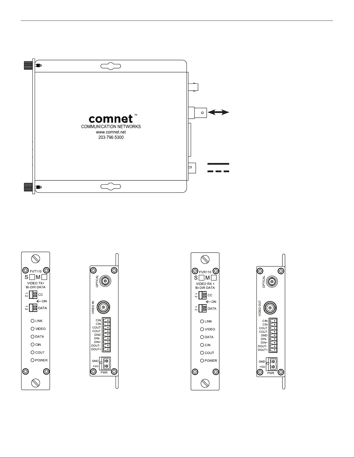
FIGURE 1 – FVT/FVR110 TRANSMITTER AND RECEIVER
MULTIMODE OR SINGLE MODE
OPTICAL FIBER
BLACK
BLACK WITH WHITE STRIPES
FIGURE 2 – FVT110 TRANSMITTER
REAR PANEL REAR PANELFRONT PANEL FRONT PANEL
Operating Voltage Range: 8–15 VDC
Power Consumption: 6W Max
NOTE: Remove Electrical Connector
for Rack Mount Units
FIGURE 3 – FVR110 RECEIVER
TECH SUPPORT: 1.888.678.9427
INS_FVT/FVR110_REV–
10/27/11
PAGE 2
Page 3
INSTALLATION AND OPERATION MANUAL FVT/FVR110(M,S)1[/M]
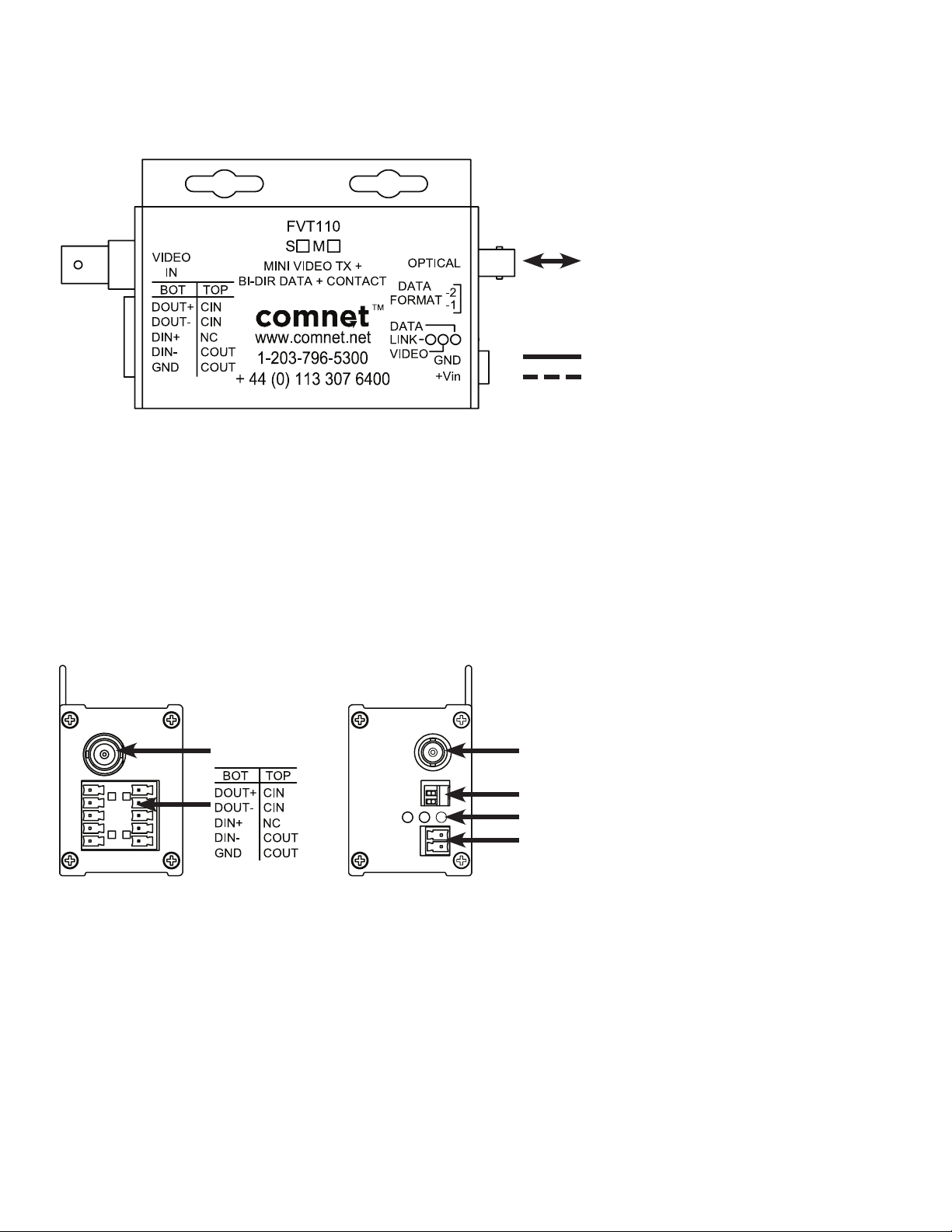
FIGURE 4 – FVT110/M TRANSMITTER
MULTIMODE OR SINGLE MODE
OPTICAL FIBER
BLACK
BLACK WITH WHITE STRIPES
Operating Voltage Range: 8–15 VDC
Power Consumption: 6W Max
FIGURE 5 – FVT110M TRANSMITTER
REAR PANELFRONT PANEL
OPTICALVIDEO IN
DATA FORMAT
LEDs: LINK VIDEO DATA
GND
+Vin
INS_FVT/FVR110_REV–
10/27/11
PAGE 3
Page 4

INSTALLATION AND OPERATION MANUAL FVT/FVR110(M,S)1[/M]
FIGURE 6 – DATA SWITCH POSITIONS
The mode for each data channel is configured using a pair of switches on the front panel of the unit.
Switch 1 Switch 2 Resulting Mode
ON ON RS232
Switch
FVT110
FVT110/M
FVR110
ON OFF
OFF ON
RS422, Bi-Phase or
Manchester
RS485 2W,
Sensornet
OFF OFF RS485 4W
GND DIN– DIN+ DOUT– DOUT+
RS232
• • •
RS422,
Bi-Phase,
• • • • •
Manchester
RS485 2W,
Sensornet
• • •
TECH SUPPORT: 1.888.678.9427
RS485 4W
• • • • •
INS_FVT/FVR110_REV–
10/27/11
PAGE 4
Page 5

INSTALLATION AND OPERATION MANUAL FVT/FVR110(M,S)1[/M]
FIGURE 7 – DATA CONNECTIONS
UTC Control
RS232
RS422
Customer
Equipment
Up-the-Coax
Control Receiver
Customer
Equipment
Data Transmit
Data Receive
Signal Ground
Data Out (+)
Data Out (–)
Data In (+)
Data In (–)
FVT110
VIDEO IN
FVT110
DIN(–)
DOUT(–)
GND
DIN(+)
DIN(–)
DOUT(+)
DOUT(–)
FVR110
VIDEO OUT
FVR110
DOUT(–)
DIN(–)
GND
DOUT(+)
DOUT(–)
DIN(+)
DIN(–)
Customer
Equipment
Up-the-Coax
Control Transmitter
Customer
Equipment
Data Receive
Data Transmit
Signal Ground
Data In (+)
Data In (–)
Data Out (+)
Data Out (–)
Bi-phase or
Manchester
2-Wire
RS485
4-Wire
RS485
Data Out (+)
Data Out (–)
Data (A)
Data (B)
Data Out (A)
Data Out (B)
Data In (A)
Data In (B)
DIN(+)
DIN(–)
DIN(+)
DIN(–)
DIN(+)
DIN(–)
DOUT(+)
DOUT(–)
DOUT(+)
DOUT(–)
DIN(+)
DIN(–)
DOUT(+)
DOUT(–)
DIN(+)
DIN(–)
Data In (+)
Data In (–)
Data (A)
Data (B)
Data In (A)
Data In (B)
Data Out (A)
Data Out (B)
INS_FVT/FVR110_REV–
10/27/11
PAGE 5TECH SUPPORT: 1.888.678.9427
Page 6

INSTALLATION AND OPERATION MANUAL FVT/FVR110(M,S)1[/M]
FIGURE 8 – CONTACT CLOSURE
The FVT110 transmits the state of a contact closure input over fiber to an output relay on the FVR110.
FVT110/MFVT110
Dry contact closure input. Applying
a voltage to these pins may damage
the unit.
NOTE: It is possible to configure the FVR110 output relay to indicate the link status instead of the contact closure input when linked to a FVT110.
Dry contact closure input. Applying
a voltage to these pins may damage
the unit.
FIGURE 9 – CONTACT CLOSURE SWITCH SETTINGS
The switch is located on the front of the standard size units. The FVT110M small-size unit only supports the CIN mode.
The FV110 series includes support for bi-directional contacts. The FVT110 and the FVR110 have 4 different modes to set
their COUT contact, set by the CC dipswitches:
Switch 1 Switch 2 Resulting Mode
ON ON CIN
OFF ON Negative CIN
ON OFF Negative Link
OFF OFF Link
The CIN and Negative CIN modes transmit the status or negative status of a contact device, such as an alarm, from the
source to sink. The source takes the contact state from the CIN pins and turns the state into digital information to be
transmitted through the fiber connection to the sink. The sink then interprets the received digital information back into the
contact state, or negative contact state to the COUT pins, depending on what mode is selected by the sink.
The Link and Negative Link modes affect the COUT pins of the sink based on the status of the fiber link between the source
and the sink. In the Link mode, if a fiber link is present between the sink and the source, the sink will close the COUT pins.
If a Fiber Link is not present in Link mode, the sink will open the COUT pins. The converse of this is true if the mode is
Negative Link.
TECH SUPPORT: 1.888.678.9427
INS_FVT/FVR110_REV–
10/27/11
PAGE 6
Page 7

INSTALLATION AND OPERATION MANUAL FVT/FVR110(M,S)1[/M]
FIGURE 10 – LED INDICATORS
LINK VIDEO DATA IN POWER CIN COUT
GREEN Communication
link has been
established over
optical fiber
RED Communication
link has not been
established.
OFF Unit powered
down.
An active video
signal is present
on the BNC
connector.
No active video
signal present
on the BNC
connector.
Unit powered
down.
An active data
Unit powered up Contact Closed Contact Closed
signal is present
on the pins of the
data connector.
– – – –
No active data
signal is present
Unit powered
down.
Contact Open Contact Open
on the pins of the
data connector.
INS_FVT/FVR110_REV–
10/27/11
PAGE 7TECH SUPPORT: 1.888.678.9427
Page 8
MECHANICAL INSTALLATION INSTRUCTIONS
INSTALLATION CONSIDERATIONS
This fiber-optic link is supplied as a Standalone/Rack module. Units should
be installed in dry locations protected from extremes of temperature and
humidity.
C1-US, C1-EU, C1-AU OR C1-CH CARD CAGE RACKS
CAUTION: Although the units are hot-swappable and may be installed
without turning power off to the rack, ComNet recommends that the
power supply be turned off and that the rack power supply is disconnected
from any power source. Note: Remove electrical connector before
installing in card cage rack.
1. Make sure that the card is oriented right side up, and slide it into the
card guides in the rack until the edge connector at the back of the card
seats in the corresponding slot in the rack’s connector panel. Seating
may require thumb pressure on the top and bottom of the card’s front
panel.
CAUTION: Take care not to press on any of the LEDs.
2. Tighten the two thumb screws on the card until the front panel of the
card is seated against the front of the rack.
WARNING: Unit is to be used with a Listed Class 2 power supply.
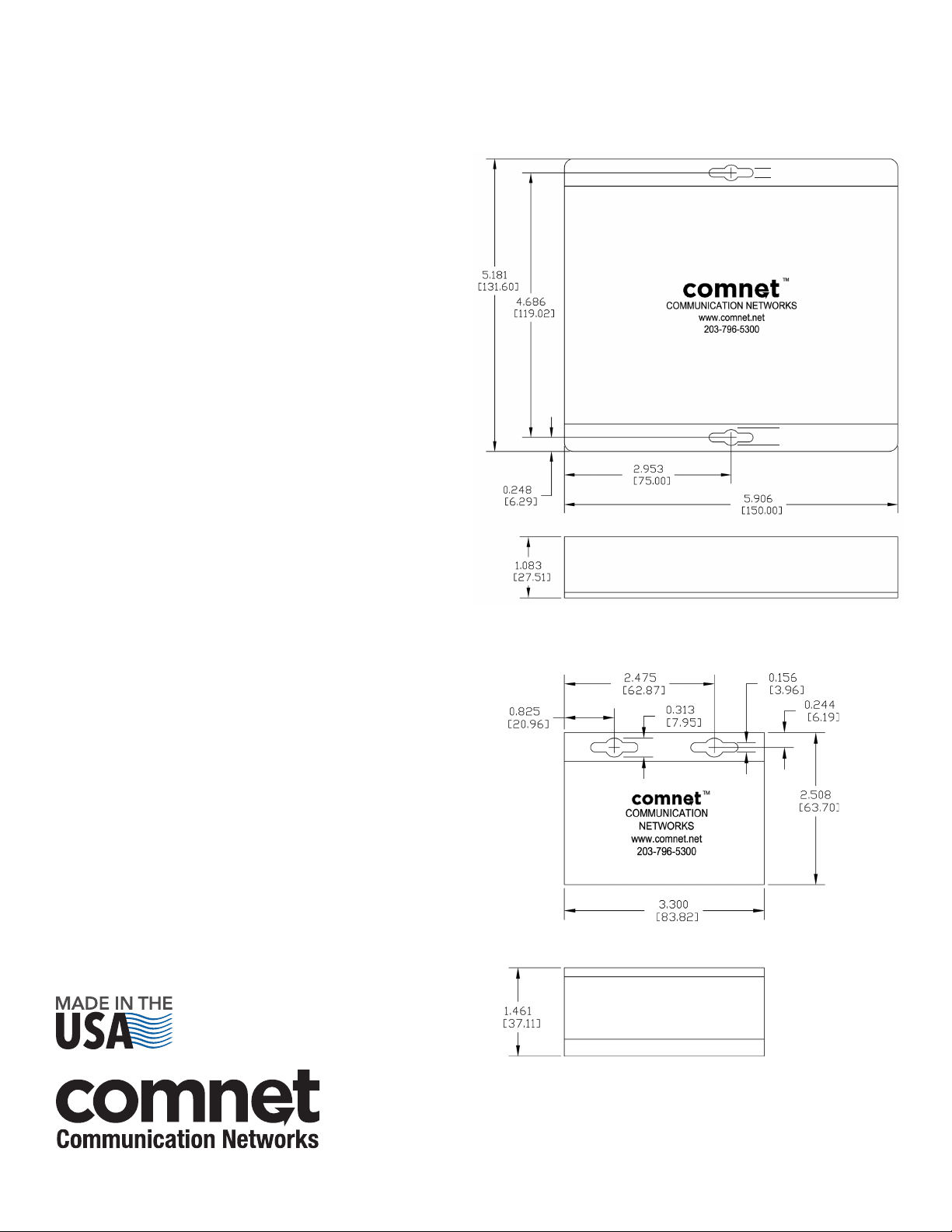
FIGURE A
Dimensions are for a standard ComNet™ one slot module
.156 [3.96 mm]
.313 [7.95 mm]
IMPORTANT SAFEGUARDS:
A) Elevated Operating Ambient - If installed in a closed or multi-unit rack
assembly, the operating ambient temperature of the rack environment may
be greater than room ambient. Therefore, consideration should be given to
installing the equipment in an environment compatible with the maximum
ambient temperature (Tma) specified by the manufacturer.
B) Reduced Air Flow - Installation of the equipment in a rack should be such
that the amount of air flow required for safe operation of the equipment is not
compromised.
FVT/FVR110(M,S)[/M] Part Ordering Options:
(M,S): Fiber Type
M: Multimode
S: Singlemode
[/M]: Mini Long Tall Enclosure (optional)
FIGURE B
Dimensions are for a ComNet™ mini long tall module
3 CORPORATE DRIVE | DANBURY, CT 06810 | USA
T: 203.796.5300 | F: 203.796.5303 | TECH SUPPORT: 1.888.678.9427 | INFO@COMNET.NET
8 TURNBERRY PARK ROAD | GILDERSOME | MORLEY | LEEDS, UK LS27 7LE
T: +44 (0)113 307 6400 | F: +44 (0)113 253 7462 | INFO-EUROPE@COMNET.NET
INS_FVT/FVR110_REV–
10/27/11
PAGE 8© 2014 Communications Net works Corporation. All Rights Reserved. “ComNet” and the “C omNet Logo” are regist ered trademar ks of Communication Net works, LLC .
 Loading...