

Comnet FVT4014SHR, FVR1010SHR, FVR4014SHR, FVT1010SHR, FVR8018SHR Installation And Operation Manual
Page 1
INSTALLATION AND OPERATION MANUAL
FVT/FVR8018(M)(S)1SHR
8-CHANNEL 10-BIT DIGITALLY ENCODED VIDEO
+ 8-CHANNEL BI-DIRECTIONAL DATA
+ SELF-HEALING RING TOPOLOGIES
The FVT/FVR8018SHR are part of ComNet’s SHR product family. The FVT8018SHR
transmits eight channels of video and eight channels of bi-directional data over its
Install fiber and power up
!
receiving modem prior to
power up of FVT8018SHR
two fiber optic interfaces. The FVR8018SHR receives eight channels of video and
eight channels of bi-directional data over its two fiber optic interfaces. The
FVT/FVR8018SHR are fully compatible with the other products in ComNet’s SHR product
family (e.g. FVT/FVR1010SHR and FVT/FVR4014SHR).
The NTSC or PAL video signals are digitized with 10-bits of resolution providing
superior image quality. The link also transmits bi-directional data over the same fiber.
Each data channel can be configured for an electrical interface of RS232, RS422 or
RS485 (2 Wire or 4 Wire).
Utilizing wave division multiplexing (WDM) technology, only one optical fiber is required
between units. It’s possible to implement a fully self-healing ring, linear add-drop, and even
point-to-point topologies. A maximum of eight (8) video signals can be placed onto the ring
through any combination of transmitter units, and an unlimited number of receiver units
can be used to view any or all of these eight video signals.
Bi-Color (Red/Green) LED indicators are provided for rapidly ascertaining equipment
operating status including the location of fiber breaks. See Figure 10 on Page 7 for an
explanation of LED indicators. An alarm relay output on the FVR8018SHR indicates when a
fault has occurred anywhere in the system.
These units are interchangeable between stand-alone or card-cage mount configurations.
See Figure A on Page 11 for mounting instructions.
See Figures 1 – 13 for complete installation information.
INS_FVT/FVR8018SHR_REVA
11/14/11
PAGE 1
Page 2
INSTALLATION AND OPERATION MANUAL FVT/FVR8018SHR
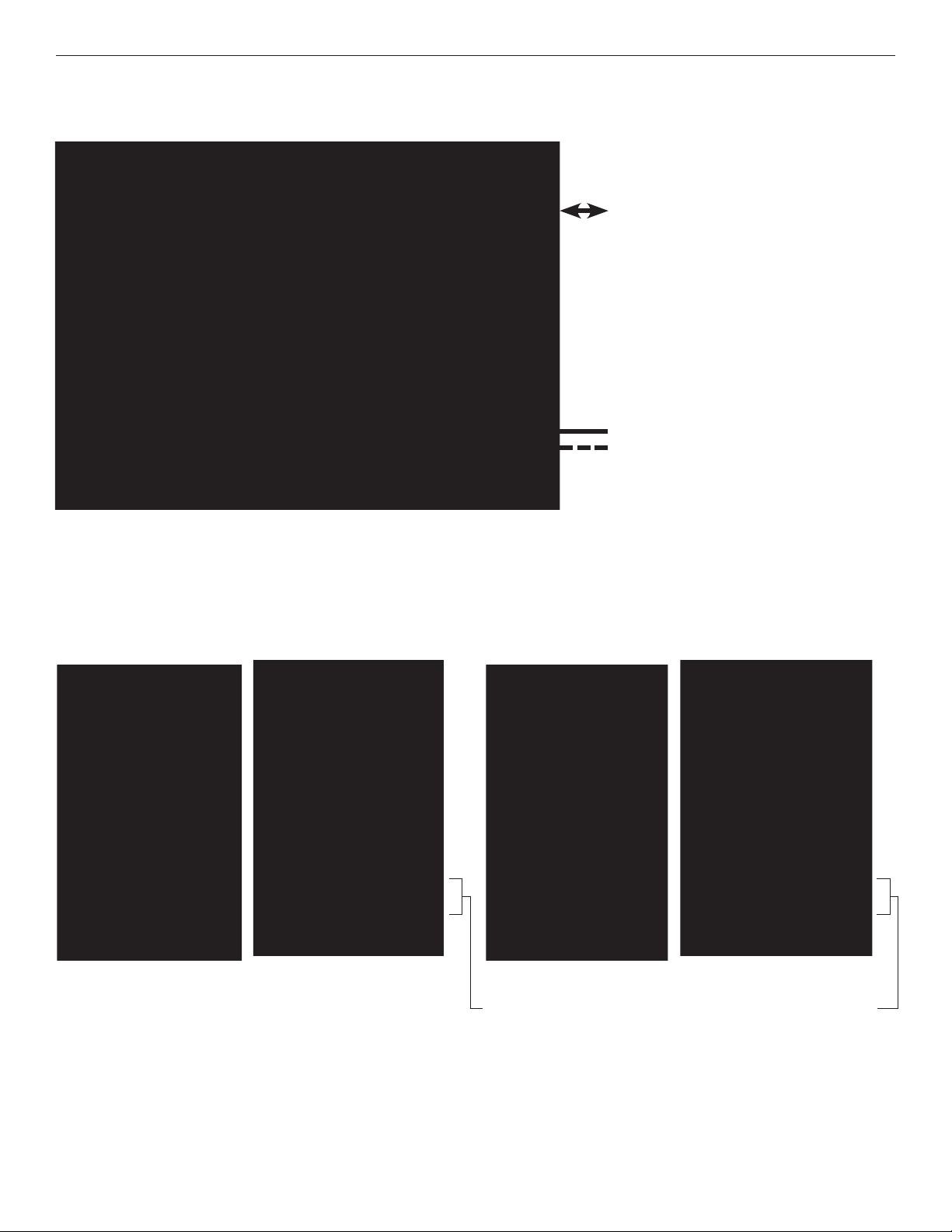
FIGURE 1 – FVT/FVR8018SHR TRANSMITTER AND RECEIVER
MULTIMODE OR SINGLE MODE
OPTICAL FIBER (Depending on Model)
BLACK
BLACK WITH WHITE STRIPE
Power Supply:
Surface Mount: 8–15 VDC @ 3W
Rack Mount: From Rack
FIGURE 2 – FVT8018SHR TRANSMITTER
REAR PANEL REAR PANELFRONT PANEL FRONT PANEL
FIGURE 3 – FVR8018SHR RECEIVER
NOTE: Remove Electrical Connector for Rack Mount Units
TECH SUPPORT: 1.888.678.9427
INS_FVT/FVR8018SHR_REVA
11/14/11
PAGE 2
Page 3
INSTALLATION AND OPERATION MANUAL FVT/FVR8018SHR
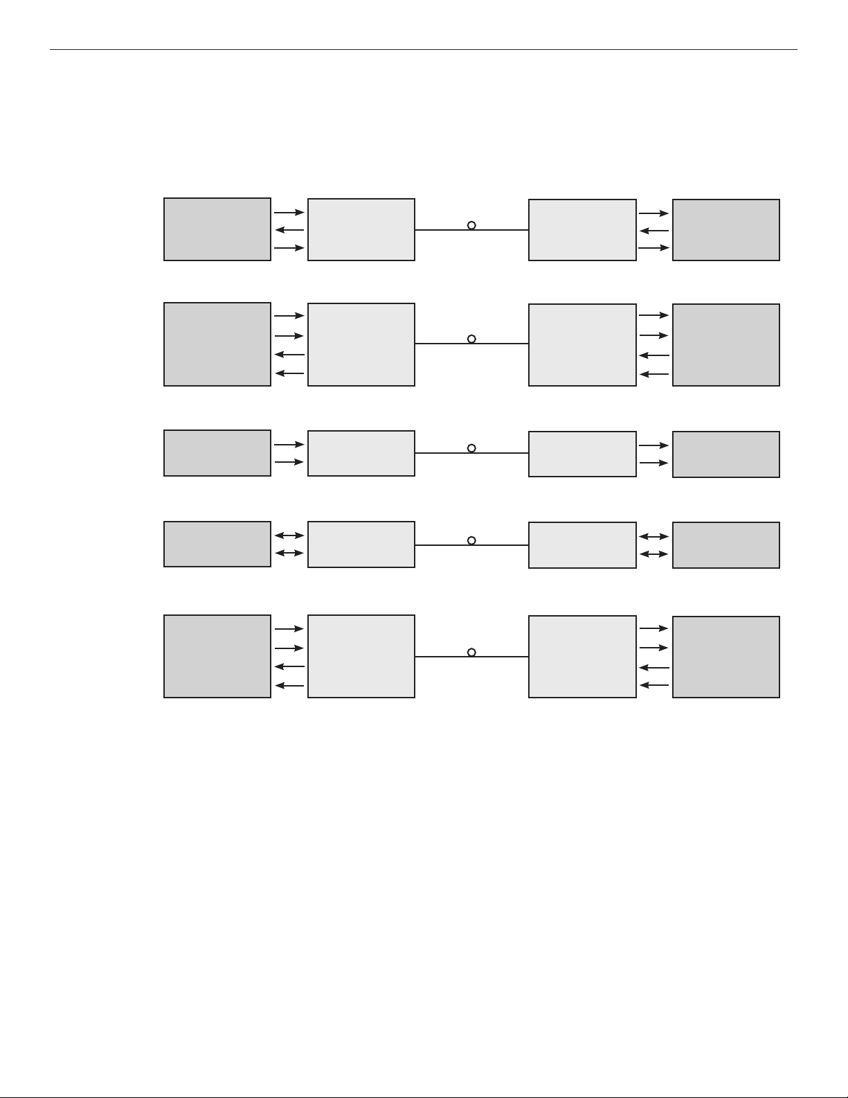
FIGURE 4 – DATA CONNECTIONS
See Figure 6 for Switch Positions
RS232
RS422
Bi-phase or
Manchester
2-Wire
RS485
Customer
Equipment
Data Transmit
Data Receive
Signal Ground
Data Out (+)
Data Out (–)
Data In (+)
Data In (–)
Data Out (+)
Data Out (–)
Data (A)
Data (B)
FVT8018SHR
DIN(–)
DOUT(–)
GND
DIN(+)
DIN(–)
DOUT(+)
DOUT(–)
DIN(+)
DIN(–)
DIN(+)
DIN(–)
FVR8018SHR
DOUT(–)
DIN(–)
GND
DOUT(+)
DOUT(–)
DIN(+)
DIN(–)
DOUT(+)
DOUT(–)
DIN(+)
DIN(–)
Customer
Equipment
Data Receive
Data Transmit
Signal Ground
Data In (+)
Data In (–)
Data Out (+)
Data Out (–)
Data In (+)
Data In (–)
Data (A)
Data (B)
Data Out (A)
4-Wire
RS485
Data Out (B)
Data In (A)
Data In (B)
TECH SUPPORT: 1.888.678.9427
DIN(+)
DIN(–)
DOUT(+)
DOUT(–)
DOUT(+)
DOUT(–)
DIN(+)
DIN(–)
Data In (A)
Data In (B)
Data Out (A)
Data Out (B)
INS_FVT/FVR8018SHR_REVA
11/14/11
PAGE 3
Page 4
INSTALLATION AND OPERATION MANUAL FVT/FVR8018SHR
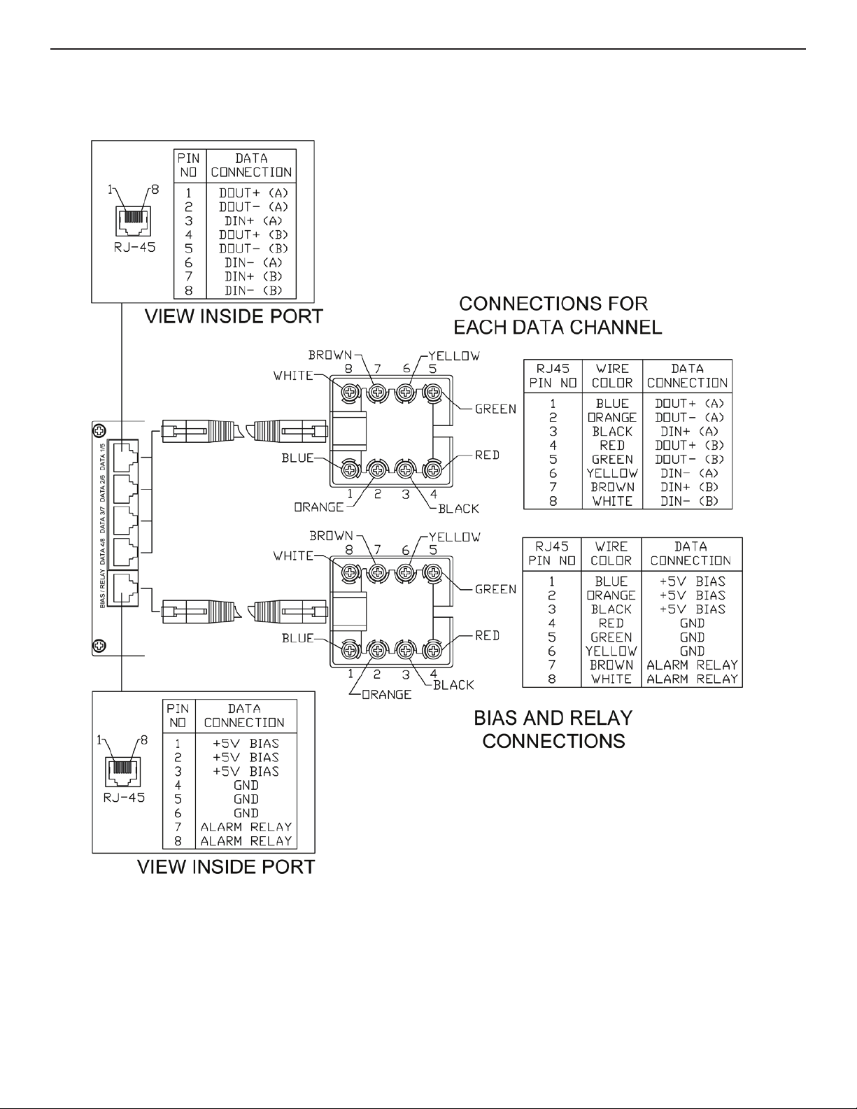
FIGURE 5 – RJ45 BREAK-OUT
5 pc. Factory Supplied
TECH SUPPORT: 1.888.678.9427
INS_FVT/FVR8018SHR_REVA
11/14/11
PAGE 4
Page 5

INSTALLATION AND OPERATION MANUAL FVT/FVR8018SHR
FIGURE 6 – DATA SWITCH POSITIONS
The mode for each data channel is configured using a pair of switches on the front panel of the unit.
Switch
FIGURE 7 – SWITCH SETTINGS
A Ports - Data Channels 1-4
B Ports - Data Channels 5-8
RS232
1 NC
2 Out A (-)
3 Ground A
4 NC
5 OUT B (-)
6 IN A (-)
7 GROUND B
8 IN B (-)
RS485 (2W)
& SENSORNET
1 NC
2 NC
3 IN A (+)
4 NC
5 NC
6 IN A (-)
7 IN B (+)
8 IN B (-)
RS422, RS485 (4W),
Manchester
& Bi-Phase
1 OUT A (+)
2 OUT A (-)
3 IN A (+)
4 OUT B (+)
5 OUT B (-)
6 IN A (-)
7 IN B (+)
8 IN B (-)
NC = No Connection
TECH SUPPORT: 1.888.678.9427
INS_FVT/FVR8018SHR_REVA
11/14/11
PAGE 5
Page 6

INSTALLATION AND OPERATION MANUAL FVT/FVR8018SHR
FIGURE 8 – FIBER CONNECTIONS
Many ring configurations are possible, including the addition of other Video/Data units in the ComNet SHR Product Line. Note that
Optic A is always connected to Optic B on the next unit.
Self Healing Ring:
FVT4014SHR FVR1010SHRFVT4014SHR FVR4014SHR FVR8018SHR
Linear:
OPTICAL
FIBERS
OPTICAL
FIBERS
OPTIC A
OPTIC B
OPTIC A
OPTIC B
OPTIC A
OPTIC B
OPTIC A
OPTIC B
OPTIC A
OPTIC B
FVT1010SHR FVT1010SHRFVT1010SHR FVT1010SHR FVR4014SHR
OPTIC A
OPTIC B
OPTIC A
OPTIC B
OPTIC A
OPTIC B
OPTIC A
OPTIC B
OPTIC A
OPTIC B
TECH SUPPORT: 1.888.678.9427
INS_FVT/FVR8018SHR_REVA
11/14/11
PAGE 6
Page 7

INSTALLATION AND OPERATION MANUAL FVT/FVR8018SHR
FIGURE 9 – SHR SWITCH POSITIONS
DCH1/SHR Switch
1 2
Resulting Configuration
NA* ON Disable Remote Fault Locator (RFL) feature
NA* OFF Enable Remote Fault Locator (RFL) feature
* Switch 1 on the FVT/FVR8018SHR unit is not used currently and is reserved
for a future release.
FIGURE 10 – LED INDICATORS
OPTIC A/B VIDEO DATA POWER
GREEN
RED
GREEN/RED
BLINK
OFF
Communication link has been established
over optical fiber
Communication link has not been
established.
Communication has been established
over optical fiber. However a fiber break
has been detected in the system.
Unit powered down Unit powered down No data signal is present. Unit powered down
An active video signal is present on
the BNC connector.
No video signal is present.
– – –
SHR Switch 2 can disable the Remote Fault Locator (RFL) feature of the OPTIC
A and OPTIC B LEDs as described in Figure 10. For self-healing ring topologies,
this switch would normally be turned OFF at every unit in the system so that
the RFL is enabled. However, for linear topologies this switch would be turned
ON at the two end points and turned OFF at the rest of the units. Disabling the
RFL at these two locations prevents them reporting their disconnected optic
ports as a fault to the rest of the units in the system. Fiber breaks throughout
the rest of the system will still be reported normally, even at the two endpoints. It is also possible to completely disable the RFL by setting this switch to
the ON position at every unit in the system. In this case, the OPTIC A and OPTIC
B LEDs will only report the status of the optical link between this unit and the
next; the LEDs would either be solid green or solid red.
An active data signal is present on the
pins of the data connector.
Unit powered up
– –
Remote Fault Locator (RFL) using the OPTIC LEDs
The Bi-color OPTIC A and OPTIC B LEDs on the front panel convey the status of the optical link between one unit and the next unit around the ring, as well as
the status of the ring as a whole. They can be used to identify the location of a remote fiber fault based on their color and pattern:
• Solid Green Optical link has been established between this optical port and the adjacent unit over fiber.
Furthermore, every other unit in the system is also reporting that link has been established.
There are no faults in the system.
• Solid Red Optical link over this port has been lost.
This could be due to a broken fiber, a bad connection, or loss of power at the adjacent unit.
• Blinking
Green/Red Optical link has been established between this optical port and the adjacent SHR unit.
However, a fault condition has been detected somewhere in the system. The OPTIC LED will be green for a period of time, and
then flash red some number of times. The number of red flashes indicates the location of the fault by “hops” around the ring. If
the LED flashes red three times, then the location of the fault is three hops away (i.e. three SHR units away). For larger systems
with faults greater than 9 hops away, the LED will use a combination of long and short red flashes. Each long flash indicates 10
hops. Each short flash indicates 1 hop. For example, a fault 47 hops away would be encoded as 4 long red flashes, followed
immediately by 7 short red flashes. The pattern repeats indefinitely until the fault is resolved.
INS_FVT/FVR8018SHR_REVA
TECH SUPPORT: 1.888.678.9427
11/14/11
PAGE 7
Page 8

INSTALLATION AND OPERATION MANUAL FVT/FVR8018SHR
FIGURE 11 – EXAMPLE SYSTEM IN LINEAR TOPOLOGY
The figure below shows a system with FVT/FVR1010SHR units connected in a linear topology. The system demonstrates a video distribution application.
A
A single video input is transmitted by a FVT1010SHR over fiber optic cable to three daisy-chained FVR1010SHR units. The last unit in the chain is
connected to an audible alarm to indicate faults.
Three receivers are used in this example, but there is no limit to the number of receivers used in a system. This example could also be expanded to
distribute four or eight channels of video using FVT/FVR4014SHR or FVT/FVR8018SHR units, respectively.
A
FVT1010SHR
Unit 1
VIDEO IN
B BB B
V
The table below shows the SHR configuration switches for each unit in the system. Once the system is configured, all of the POWER, OPTIC and VIDEO
B
A A A
FVR1010SHR
Unit 2
VIDEO OUT
V
FVR1010SHR
Unit 3
VIDEO OUT
V
FVR1010SHR
Unit 4
VIDEO OUT
V
LEDs will be solid green except for the OPTIC A LED on Unit 1 and the OPTIC B LED on Unit 4, which would both be solid red. No faults will be reported
because RFL has been disabled at Units 1 and Unit 4. The alarm relay will be closed.
Unit
SHR Switch
1 2 3 4
Notes
1 ON ON ON ON Transmit video on Channel 1. Do not report fiber faults to other units.
2 ON ON ON OFF Receive video from Channel 1.
3 ON ON ON OFF Receive video from Channel 1
4 ON ON ON ON Receive video from Channel 1. Do not report fiber faults to other units.
Let’s consider how the system would respond to a broken fiber between Units 2 and 3:
C
ALARM
A
FVT1010SHR
Unit 1
VIDEO IN
B BB B
V
The video would no longer be displayed at Units 3 and 4 because this is system has a linear topology (i.e. there is no redundant fiber path).
D
A A A
FVR1010SHR
Unit 2
VIDEO OUT
FIBER
BREAK
V
FVR1010SHR
Unit 3
NO VIDEO NO VIDEO
V
FVR1010SHR
Unit 4
V
The alarm relay will open and cause the audible alarm at Unit 4 to sound. In addition, the other units in the system would indicate the location of the
fault using their OPTIC LEDs as described in the table below.
Unit OPTIC A LED OPTIC B LED
1 Solid Red Green, then Blink Red 1 time
2 Solid Green Solid Red
3 Solid Red Solid Green
4 Green, then Blink Red 1 time Solid Red
INS_FVT/FVR8018SHR_REVA
TECH SUPPORT: 1.888.678.9427
ALARM
11/14/11
PAGE 8
Page 9

INSTALLATION AND OPERATION MANUAL FVT/FVR8018SHR
FIGURE 12 – EXAMPLE SYSTEM IN SELF-HEALING RING
The figure below shows a system of four FVT1010SHR units, a FVT4014SHR unit and a FVR8018SHR unit connected as a self-healing ring. Eight channels of
A
video enter the system at the five transmitter units and are sent to the video receiver and are displayed on a bank of monitors.
A
V
VIDEO IN
FVT1010SHR
Unit 1
B BB
A
B
V
VIDEO IN
FVT1010SHR
Unit 2
FVT4014SHR
Unit 5
4
A
VIDEO IN
1 – 4
V
VIDEO IN
A A
FVT1010SHR
Unit 3
FVR8018SHR
B
Unit 6
8
B
A
VIDEO OUT 1 – 8
(e.g., Bank of Monitors)
V
VIDEO IN
FVT1010SHR
Unit 4
VV
The table below shows the SHR configuration switches for each unit in the system. Once the system is configured, all of the POWER, OPTIC and VIDEO
B
LEDs will be solid green. No faults will be reported.
Unit
SHR Switch
1 2 3 4
Notes
1 ON ON ON OFF Transmit video on Channel 1.
2 OFF ON ON OFF Transmit video on Channel 2.
3 ON OFF ON OFF Transmit video on Channel 3.
4 OFF OFF ON OFF Transmit video on Channel 4.
Unit
5 OFF OFF Transmit video on Channels 5 – 8
6 NA* OFF Receive video from Channels 1 – 8
Switch 1 on the FVR8018SHR unit is not used currently and is reserved for a
future release.
SHR Switch
1 2
Notes
TECH SUPPORT: 1.888.678.9427
INS_FVT/FVR8018SHR_REVA
11/14/11
PAGE 9
Page 10

INSTALLATION AND OPERATION MANUAL FVT/FVR8018SHR
FIGURE 13 – EXAMPLE SYSTEM IN SELF-HEALING RING (CONT’D)
Let’s consider how the system would respond to a broken fiber between Units 2 and 3:
C
A
V
VIDEO IN
FVT1010SHR
Unit 1
B BB
A
B
V
VIDEO IN
FVT1010SHR
Unit 2
FVT4014SHR
Unit 5
4
A
VIDEO IN
1 – 4
FIBER
BREAK
V
VIDEO IN
A A
FVT1010SHR
Unit 3
FVR8018SHR
B
Unit 6
8
B
A
VIDEO OUT 1 – 8
(e.g., Bank of Monitors)
V
VIDEO IN
FVT1010SHR
Unit 4
VV
Because the system is connected as a self-healing ring, all eight channels of video will still be displayed even after the fiber break. All of the units in the
D
system will indicate the location of the fault using their OPTIC LEDs as described in the table below.
Unit Optic A LED Optic B LED
1 Green, then blink Red 4 times Green, then blink Red 1 time
2 Green, then blink Red 5 times Solid Red
3 Solid Red Green, then blink Red 5 times
4 Green, then Blink Red 1 time Green, then blink Red 4 times
5 Green, then blink Red 3 times Green, then blink Red 2 times
6 Green, then blink Red 2 times Green, then blink Red 3 times
TECH SUPPORT: 1.888.678.9427
INS_FVT/FVR8018SHR_REVA
11/14/11
PAGE 10
Page 11

MECHANICAL INSTALLATION INSTRUCTIONS
INSTALLATION CONSIDERATIONS
This fiber-optic link is supplied as a Standalone/Rack module. Units should
be installed in dry locations protected from extremes of temperature and
humidity.
C1-US, C1-EU, C1-AU OR C1-CH CARD CAGE RACKS
CAUTION: Although the units are hot-swappable and may be installed
without turning power off to the rack, ComNet recommends that the
power supply be turned off and that the rack power supply is disconnected
from any power source. Note: Remove electrical connector before
installing in card cage rack.
1. Make sure that the card is oriented right side up, and slide it into the
card guides in the rack until the edge connector at the back of the card
seats in the corresponding slot in the rack’s connector panel. Seating
may require thumb pressure on the top and bottom of the card’s front
panel.
CAUTION: Take care not to press on any of the LEDs.
2. Tighten the two thumb screws on the card until the front panel of the
card is seated against the front of the rack.
WARNING: Unit is to be used with a Listed Class 2 or LPS power supply rated 8-15
VDC @ 3W.
FIGURE A
Dimensions are for a standard ComNet™ three slot module
.156 [3.96 mm]
.313 [7.95 mm]
IMPORTANT SAFEGUARDS:
A) Elevated Operating Ambient - If installed in a closed or multi-unit rack
assembly, the operating ambient temperature of the rack environment may
be greater than room ambient. Therefore, consideration should be given to
installing the equipment in an environment compatible with the maximum
ambient temperature (Tma) specified by the manufacturer.
B) Reduced Air Flow - Installation of the equipment in a rack should be such
that the amount of air flow required for safe operation of the equipment is not
compromised.
3 CORPORATE DRIVE | DANBURY, CT 06810 | USA
T: 203.796.5300 | F: 203.796.5303 | TECH SUPPORT: 1.888.678.9427 | INFO@COMNET.NET
8 TURNBERRY PARK ROAD | GILDERSOME | MORLEY | LEEDS, UK LS27 7LE
T: +44 (0)113 307 6400 | F: +44 (0)113 253 7462 | INFO-EUROPE@COMNET.NET
© 2011 Communicat ions Network s Corporation. All Rights Reserved. “ComNet” and the “ComNet L ogo” are registered tr ademarks of Communication Networks, LLC.
INS_FVT/FVR8018SHR_REVA
11/14/11
PAGE 11
 Loading...