

Comnet FVT1D11, FVT1D1M1, FVT1D1S1, FVT1D1M1/M, FVR1D11 Installation And Operation Manual
...Page 1

INSTALLATION AND OPERATION MANUAL
FVT/FVR1D1(M,S)1[/M]
FVR2D2(M,S)2
DIGITALLY ENCODED VIDEO WITH BI-DIRECTIONAL DATA
AND SIMPLEX CONTACT CLOSURE
The ComNet™ FV T1D1[/M] video transmitter, along with the FVR1D1 and FVR2D2,
supports the transmission of digital video transmission and bi-directional RS422 or
2- or 4-wire RS485 data channel over multimode or single mode optical fiber(s).
When the unit is operated in the RS422 2-wire data mode, a simplex contact closure
channel is available. This module is universally compatible with major CCTV camera
manufacturers. Plug-and-play design ensures ease of installation and no electrical or
optical adjustments are ever required.
Each unit incorporates a bi-color (Red/Green) indicating LED for monitoring proper
system operation. See Figure 9 on Page 6 for LED Indicator explanations.
The ComFit units in this series may be directly plugged into the ComNet Rack
(Part C1) or may be either wall-mounted, rack-mounted, or DIN-rail mounted by
the addition of ComNet model DINBKT1 adaptor plate. The small-size FVT1D1/M
transmitters are ideal for locations where space is at a premium and are surface mount
only. See Figure A on Page 8 for mounting instructions.
See Figures 1 – 12 for complete installation details.
INS_FVT/FVR1D1(M,S)1[M]_FVR2D2(M,S)2_REV– 04/05/12 PAGE 1
Page 2
INSTALLATION AND OPERATION MANUAL FVT/FVR1D1(M,S)1[/M] & FVR2D2(M,S)2
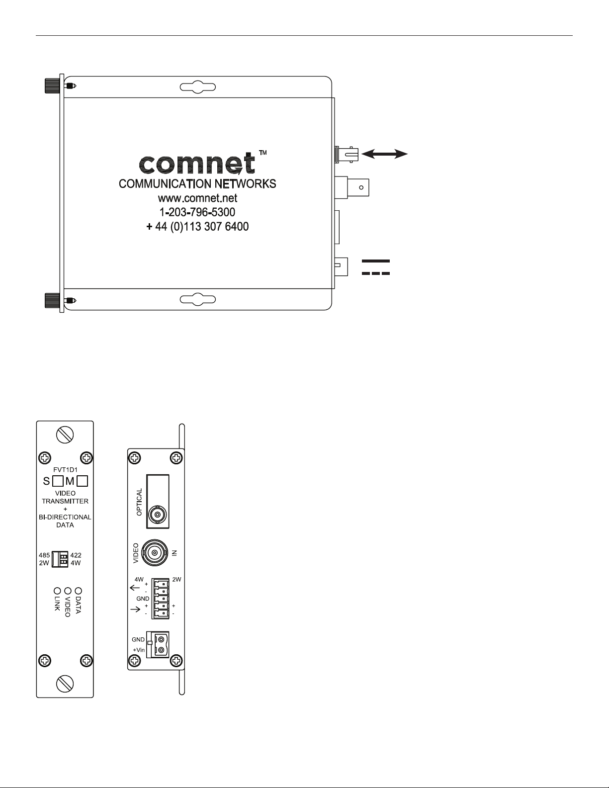
FIGURE 1 – FVT1D1 TRANSMITTER
MULTIMODE OR
SINGLE MODE
OPTICAL FIBER
BLACK
BLACK WITH WHITE STRIPE/RED
Power Supply:
Surface Mount: 9-36 VDC @ 3W
Rack Mount: From Rack
NOTE: Remove Electrical
Connector for Rack Mount Units
FIGURE 2 – FVT1D1 TRANSMITTER
REAR PANELFRONT PANEL
TECH SUPPORT: 1.888.678.9427
INS_FVT/FVR1D1(M,S)1[M]_FVR2D2(M,S)2_REV– 04/05/12 PAGE 2
Page 3

INSTALLATION AND OPERATION MANUAL FVT/FVR1D1(M,S)1[/M] & FVR2D2(M,S)2
FIGURE 3 – FVR1D1 RECEIVER
MULTIMODE OR
SINGLE MODE
OPTICAL FIBER
BLACK
BLACK WITH WHITE STRIPE/RED
FIGURE 4 – FVR1D1 RECEIVER
REAR PANELFRONT PANEL
Power Supply:
Surface Mount: 9-36 VDC @ 3W
Rack Mount: From Rack
NOTE: Remove Electrical
Connector for Rack Mount Units
TECH SUPPORT: 1.888.678.9427
INS_FVT/FVR1D1(M,S)1[M]_FVR2D2(M,S)2_REV– 04/05/12 PAGE 3
Page 4

INSTALLATION AND OPERATION MANUAL FVT/FVR1D1(M,S)1[/M] & FVR2D2(M,S)2
FIGURE 5 – FVR2D2 RECEIVER
MULTIMODE OR
SINGLE MODE
OPTICAL FIBER
BLACK
BLACK WITH WHITE STRIPE/RED
FIGURE 6 – FVR2D2 RECEIVER
REAR PANELFRONT PANEL
Power Supply:
Surface Mount: 9-36 VDC @ 3W
Rack Mount: From Rack
NOTE: Remove Electrical
Connector for Rack Mount Units
TECH SUPPORT: 1.888.678.9427
INS_FVT/FVR1D1(M,S)1[M]_FVR2D2(M,S)2_REV– 04/05/12 PAGE 4
Page 5

INSTALLATION AND OPERATION MANUAL FVT/FVR1D1(M,S)1[/M] & FVR2D2(M,S)2
FIGURE 7 – FVT1D1/M TRANSMITTER
BLACK
BLACK WITH WHITE STRIPE/RED
Power Supply: 9-36 VDC @ 3W, 24VAC
AC: pins 1 and 2
DC: pins 2 and 3
FIGURE 8 – FVT1D1/M TRANSMITTER
REAR PANELFRONT PANEL
TECH SUPPORT: 1.888.678.9427
INS_FVT/FVR1D1(M,S)1[M]_FVR2D2(M,S)2_REV– 04/05/12 PAGE 5
Page 6

INSTALLATION AND OPERATION MANUAL FVT/FVR1D1(M,S)1[/M] & FVR2D2(M,S)2
FIGURE 9 – LED INDICATORS
LINK VIDEO DATA
GREEN Communication link
has been established
over optical fiber
RED Communication link has
not been established
OFF Unit Powered Down
An active video signal
is present on the BNC
connector
– –
FIGURE 10 – DIP SWITCH SETTINGS
Mode Data Switch Position Wire Switch Position
2 Wire RS485 485 2W
RS422 Simplex + Contact Closure 422 2W
4 Wire RS485 485 4W
4 Wire RS422 Duplex 422 4W
An active data signal is
present on the input pins
of the data connector
INS_FVT/FVR1D1(M,S)1[M]_FVR2D2(M,S)2_REV– 04/05/12 PAGE 6TECH SUPPORT: 1.888.678.9427
Page 7

INSTALLATION AND OPERATION MANUAL FVT/FVR1D1(M,S)1[/M] & FVR2D2(M,S)2
FIGURE 11 – TRANSMITTER DATA CONNECTIONS
RS485/2W
5
4
3
2
1
RS422/2W + CONTACT CLOSURE
5
4
3
2
1
NC
NC
GND
O
DATA (A)
O
DATA (B)
NC
CONTACT IN (+)
GND / CONTACT IN (–)
DATA OUT (+)
DATA OUT (–)
FIGURE 12 – RECEIVER DATA CONNECTIONS
RS485/2W
RS485/4W OR RS422/4W
5
4
3
2
1
RS485/4W OR RS422/4W
O
O
O
DATA OUT (+)
O
DATA OUT (–)
GND
DATA IN (+)
DATA IN (–)
5
4
3
2
1
RS422/2W + CONTACT CLOSURE
5
4
3
2
1
O
O
O
O
O
O
NC
NC
GND
DATA (A)
DATA (B)
CONTACT OUT (+)
CONTACT OUT (–)
GND
DATA IN (+)
DATA IN (–)
5
4
3
2
1
O
O
O
DATA OUT (+)
O
DATA OUT (–)
GND
DATA IN (+)
DATA IN (–)
TECH SUPPORT: 1.888.678.9427
INS_FVT/FVR1D1(M,S)1[M]_FVR2D2(M,S)2_REV– 04/05/12 PAGE 7
Page 8

MECHANICAL INSTALLATION INSTRUCTIONS
INSTALLATION CONSIDERATIONS
The ComFit fiber optic links in this series are supplied as a Standalone/
Rack module. The FVT1D1/M is supplies as a Standalone/Surface-mount
module. Units should be installed in dry locations protected from
extremes of temperature and humidity.
C1-US, C1-EU, C1-AU OR C1-CH CARD CAGE RACKS
CAUTION: Although the units are hot-swappable and may be installed
without turning power off to the rack, ComNet recommends that the
power supply be turned off and that the rack power supply is disconnected
from any power source. Note: Remove electrical connector before
installing in card cage rack.
1. Make sure that the card is oriented right side up, and slide it into the
card guides in the rack until the edge connector at the back of the card
seats in the corresponding slot in the rack’s connector panel. Seating
may require thumb pressure on the top and bottom of the card’s front
panel.
CAUTION: Take care not to press on any of the LEDs.
2. Tighten the two thumb screws on the card until the front panel of the
card is seated against the front of the rack.
FIGURE A
Dimensions are for a standard ComNet one slot module
.156 [3.96 mm]
.313 [7.95 mm]
WARNING: Unit is to be used with a listed Class 2 power supply.
IMPORTANT SAFEGUARDS:
A) Elevated Operating Ambient - If installed in a closed or multi-unit rack
assembly, the operating ambient temperature of the rack environment may
be greater than room ambient. Therefore, consideration should be given to
installing the equipment in an environment compatible with the maximum
ambient temperature (Tma) specified by the manufacturer.
B) Reduced Air Flow - Installation of the equipment in a rack should be such
that the amount of air flow required for safe operation of the equipment is not
compromised.
FIGURE B
Dimensions are for a ComNet™ small size module
3 CORPORATE DRIVE | DANBURY, CT 06810 | USA
T: 203.796.5300 | F: 203.796.5303 | TECH SUPPORT: 1.888.678.9427 | INFO@COMNET.NET
8 TURNBERRY PARK ROAD | GILDERSOME | MORLEY | LEEDS, UK LS27 7LE
T: +44 (0)113 307 6400 | F: +44 (0)113 253 7462 | INFO-EUROPE@COMNET.NET
© 2013 Communications Ne tworks Cor poration. All Rights Reser ved. “ComNet ” and the “ComNet L ogo” are registered trademarks of C ommunication Networks, LLC.
INS_FVT/FVR1D1(M,S)1[M]_FVR2D2(M,S)2_REV– 04/05/12 PAGE 8
 Loading...