

Page 1

INSTALLATION AND OPERATION MANUAL
FVR21
DUAL INDEPENDENT AM VIDEO RECEIVER
WITH MANUAL GAIN CONTROL
The ComNet™ FVR21 dual video receiver detects two independent AM video signals
in one module on two independent multimode fiber optic cables. The module is
not a multiplexer. The module is ideal for CCTV installations and the rack mount
version can be used to double the fixed video capacity of the C1 rack for up to 28
independent video channels per card cage. The modules utilize Manual Gain Control.
The receiver is compatible with the ComNet FVT11M single video transmitter and the
FVT20 dual video transmitter.
Each receiver incorporates a bi-color (Red/Green) indicating LED for monitoring proper
system operation. See Figure 3 on Page 2 for LED Indicator explanations.
The FVR21 may be directly plugged into the ComNet Rack (Part C1) or may be either
wall-mounted, rack-mounted, or DIN-rail mounted by the addition of ComNet model
DINBKT1 adaptor plate. See Figure A on Page 3 for mounting instructions.
See Figures 1 – 3 for complete installation details.
INS_FVR21_REV–
09/30/11
PAGE 1
Page 2
INSTALLATION AND OPERATION MANUAL FVR21
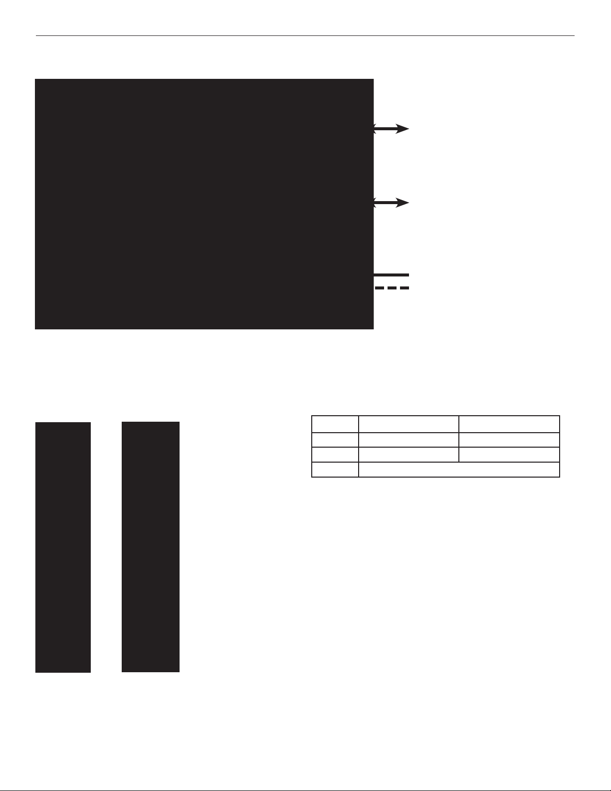
FIGURE 1 – FVR21
MULTIMODE OPTICAL FIBER
MULTIMODE OPTICAL FIBER
BLACK
BLACK WITH WHITE STRIPE/RED
Power Supply:
Surface Mount: 8–15 VDC @ 130mA
Rack Mount: From Rack
NOTE: Remove Electrical
Connector for Rack Mount Units
FIGURE 2 – FVR21 RECEIVER
REAR PANELFRONT PANEL
FIGURE 3 – LED INDICATORS
VIDEO PRESENT - Channel 1 VIDEO PRESENT - Channel 2
GREEN Activity Activity
RED No Activity No Activity
OFF Unit Powered Down
TECH SUPPORT: 1.888.678.9427
INS_FVR21_REV–
09/30/11
PAGE 2
Page 3

MECHANICAL INSTALLATION INSTRUCTIONS
INSTALLATION CONSIDERATIONS
This fiber-optic link is supplied as a Standalone/Rack module. Units should
be installed in dry locations protected from extremes of temperature and
humidity.
C1-US, C1-EU, C1-AU OR C1-CH CARD CAGE RACKS
CAUTION: Although the units are hot-swappable and may be installed
without turning power off to the rack, ComNet recommends that the
power supply be turned off and that the rack power supply is disconnected
from any power source. Note: Remove electrical connector before
installing in card cage rack.
1. Make sure that the card is oriented right side up, and slide it into the
card guides in the rack until the edge connector at the back of the card
seats in the corresponding slot in the rack’s connector panel. Seating
may require thumb pressure on the top and bottom of the card’s front
panel.
CAUTION: Take care not to press on any of the LEDs.
2. Tighten the two thumb screws on the card until the front panel of the
card is seated against the front of the rack.
WARNING: Unit is to be used with a Listed Class 2 or LPS power supply.
FIGURE A
Dimensions are for a standard ComNet one slot module
.156 [3.96 mm]
.313 [7.95 mm]
IMPORTANT SAFEGUARDS:
A) Elevated Operating Ambient - If installed in a closed or multi-unit rack
assembly, the operating ambient temperature of the rack environment may
be greater than room ambient. Therefore, consideration should be given to
installing the equipment in an environment compatible with the maximum
ambient temperature (Tma) specified by the manufacturer.
B) Reduced Air Flow - Installation of the equipment in a rack should be such
that the amount of air flow required for safe operation of the equipment is not
compromised.
3 CORPORATE DRIVE | DANBURY, CT 06810 | USA
T: 203.796.5300 | F: 203.796.5303 | TECH SUPPORT: 1.888.678.9427 | INFO@COMNET.NET
8 TURNBERRY PARK ROAD | GILDERSOME | MORLEY | LEEDS, UK LS27 7LE
T: +44 (0)113 307 6400 | F: +44 (0)113 253 7462 | INFO-EUROPE@COMNET.NET
© 2012 Communications Network s Corporation. All Rights Res erved. “ComN et” and the “ComNet Logo” are regi stered trademarks of Communic ation Networks, L LC.
INS_FVR21_REV–
09/30/11
PAGE 3
 Loading...