

Page 1
INSTALLATION AND OPERATION MANUAL
CNFE200(X)[POE](M,S)(1,2)[HO][/M]
2 CHANNEL 10/100 MBPS ETHERNET
ELECTRICAL TO OPTICAL MEDIA CONVERTER
WITH OPTIONAL POWER OVER ETHERNET (POE+)
The ComNet Ethernet CNFE200(X) media converter series are two-channel Ethernet
electrical to optical media converters with optional PoE+. These auto-negotiating
devices accept two 10/100 Mbps electrical inputs and convert this to a single 100
Mbps optical output. This series of media converters are available as multimode
or single-mode and one and two fiber SC and ST optical connectors. The ComNet
exclusive Demux feature allows for port isolation, replicating two media converters
over one fiber. The ComNet exclusive Mux feature prevents network video flooding
of multicast traffic with DIP switch selection of the fiber port as a dedicated uplink
path. The CNFE200(X) series can be powered by wide range AC or DC input while the
CNFE200(X)POE units meet the 802.3at standard and provide 30 watts of PoE+ power,
with an option for a 60 watt CNFE200(X)POEHO model. The PoE models are powered
by a 48 to 56 volt DC power supply (sold seperately).
LED indicators confirm operational status. All models are environmentally hardened
with no electrical or optical adjustments (Plug and Play). DIP Switches on the outside of
each unit allow for fine-tuning of features. See Figures 1 – 14 for complete operation
details. See Figures A and B for mounting instructions.
INS_CNFE200X[POE] Series_REV– 10/18/14 PAGE 1
Page 2
INSTALLATION AND OPERATION MANUAL CNFE200(X)[POE](M,S)(1,2)[HO][/M]
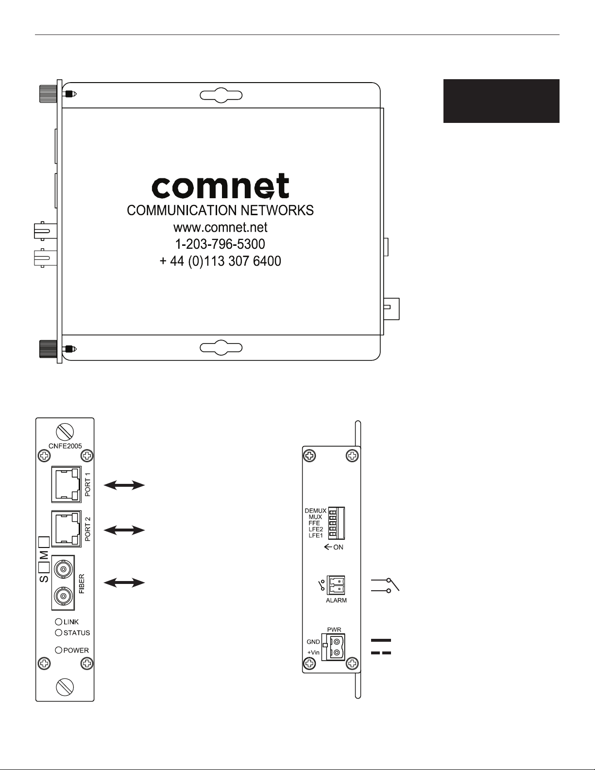
FIGURE 1 – Standard Mount DC-Only Media Converter (Non-PoE)
Figures on this page
apply to the following
model numbers:
CNFE2002M1A
CNFE2002M1B
CNFE2002S1A
CN F E2002 S1B
CNFE2003M2
CNFE2003S2
CNFE2004M1A
CNFE2004M1B
CNFE2004S1A
CN F E2004S1B
CNFE2005M2
CNFE2005S2
FIGURE 2 – Standard Mount DC-Only Media Converter (Non-PoE)
REAR PANELFRONT PANEL
CAT5/6
CAT5/6
Multimode or Single
Mode, 1 or 2 Optical Fibers
(Model Dependent)
DIP Switches
(See Fig 9)
Fault Relay
0-36V, 190mA (AC or DC)
Normally Closed (See Fig 10)
Black
Black With White Stripe
Power Supply:
Rack Mount: From Rack
Surface Mount:8 to 24 VDC
NOTE: Remove Electrical Connector for
Rack Mount Units
TECH SUPPORT: 1.888.678.9427
INS_CNFE200X[POE] Series_REV– 10/18/14 PAGE 2
Page 3
INSTALLATION AND OPERATION MANUAL CNFE200(X)[POE](M,S)(1,2)[HO][/M]
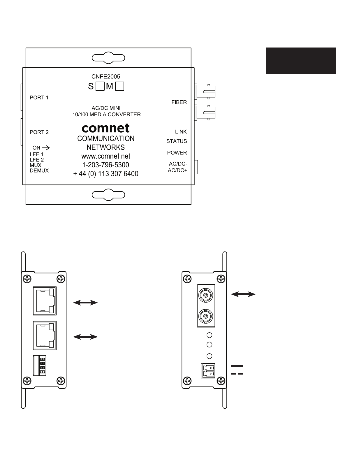
FIGURE 3 – Mini AC/DC Power Media Converter (Non-PoE)
Figures on this page
apply to the following
model numbers:
CNFE2002M1A/M
CNFE2002M1B/M
CNFE2002S1A/M
CN F E2002 S1B/M
CNFE2003M2/M
CNFE2003S2/M
CNFE2004M1A/M
CNFE2004M1B/M
CNFE2004S1A/M
CN F E2004S1B/M
CNFE2005M2/M
CNFE2005S2/M
FIGURE 4 – Mini AC/DC Power Media Converter (Non-PoE)
REAR PANELFRONT PANEL
CAT5/6
CAT5/6
DIP Switches
(See Fig 9)
Multimode or Single Mode,
1 or 2 Optical Fibers
(Model Dependent)
Black
Black With White Stripe
Power Supply:
Surface Mount:
22 to 27 VAC or 8 to 24 VDC
TECH SUPPORT: 1.888.678.9427
INS_CNFE200X[POE] Series_REV– 10/18/14 PAGE 3
Page 4

INSTALLATION AND OPERATION MANUAL CNFE200(X)[POE](M,S)(1,2)[HO][/M]
FIGURE 5 – Mini PoE Media Converter
Figures on this page
apply to the following
model numbers:
CNFE2002M1APOE/M
CNFE2002M1BPOE/M
CNFE2002S1APOE/M
CN F E2002 S1BPOE /M
CNFE2002M1APOEHO/M
CNFE2002M1BPOEHO/M
CNFE2002S1APOEHO/M
CN F E2002 S1BPOEHO /M
CNFE2003M2POE/M
CNFE2003S2POE/M
CNFE2003M2POEHO/M
CNFE2003S2POEHO/M
CNFE2004M1APOE/M
CNFE2004M1BPOE/M
CNFE2004S1APOE/M
CN F E2004S1B POE / M
CNFE2004M1APOEHO/M
FIGURE 6 – Mini PoE Media Converter
REAR PANELFRONT PANEL
CNFE2004M1BPOEHO/M
CNFE2004S1APOEHO/M
CN F E2004S1B POEHO/ M
CNFE2005M2POE/M
CNFE2005S2POE/M
CNFE2005M2POEHO/M
CNFE2005S2POEHO/M
DIP Switches
(See Fig 9)
TECH SUPPORT: 1.888.678.9427
CAT5/6
CAT5/6
Multimode or Single Mode,
1 or 2 Optical Fibers
(Model Dependent)
Black
Black With White Stripe
Power Supply: 48 to 56 volt DC
Power Consumption: 3W (without PoE load)
INS_CNFE200X[POE] Series_REV– 10/18/14 PAGE 4
Page 5

INSTALLATION AND OPERATION MANUAL CNFE200(X)[POE](M,S)(1,2)[HO][/M]
FIGURE 7 – Indicating LEDs
LINK STATUS (See Figures 8 & 9) POE 1 & 2 (PoE models only) POWER ETHERNET LINK/ACTIVITY
GREEN Communication link has
been established over
optical fiber. Flashes when
data is being transmit ted.
YELLOW N/A Fault detected (PoE models)
RED N/A Fault detected (non-PoE models)
OFF Communication link has
not been established.
FIGURE 8 – DIP Switches (CNFE200(X) Standard Size Units Only)
SW NAME OFF (DOWN) ON (UP)
1 LINK FAULT ENABLE PORT 1
2 LINK FAULT ENABLE PORT 2
3 FFE Fiber Fault Relay Disabled
4 MUX MUX Disabled
5 DEMUX DEMUX Disabled
No Fault conditions detected PoE power provided on port Unit is correctly powered up CNFE200(X) unit is
operational
N/A N/A Fiber failure or copper
(One or more DIP Switch relays
must be enabled)
N/A N/A N/A
(One or more DIP Switch relays
must be enabled)
Unit not correctly powered up PoE power not provided. Unit not correc tly powered up Unit not correctly powered
Link Fault Pass-Through Disabled
Link Fault Pass-Through Disabled
Link Fault Pass-Through Enabled.If the Copper Port is Down or Not Connected, the
Optical Port will turn on and off at a ~1 sec rate to indicate copper port 1 fault.
Link Fault Pass-Through Enabled.If the Copper Port is Down or Not Connected, the
Optical Port will turn on and off at a ~1 sec rate to indicate copper port 2 fault.
Fiber Fault Relay Enabled. If the optical link is lost or there is a power failure then the alarm
relay output will be triggered.
Mux Enabled. All Ethernet traffic is diverted from the copper ports to the fiber port,
copper-to-copper traffic will be disabled.
DeMux Enabled. When two CNFE20 0(X) units are connected via fiber and both have DeMux
enabled, traffic from Port 1 will go to Por t 1 and traffic from Port 2 will go to Port 2 only,
functioning like two separate media conver ters over one fiber.
failure (Link Fault DIP Switch
must be Enabled / ON)
up.
FIGURE 9 – DIP Switches (CNFE200(X)/M Small Size Units Only)
SW NAME OFF (DOWN) ON (UP)
1 LINK FAULT ENABLE PORT 1
2 LINK FAULT ENABLE PORT 2
3 MUX MUX Disabled
4 DEMUX DEMUX Disabled
Link Fault Pass-Through Disabled
Link Fault Pass-Through Disabled
Link Fault Pass-Through Enabled.If the Copper Port is Down or Not Connected, the
Optical Port will turn on and off at a ~1 sec rate to indicate copper port 1 fault.
Link Fault Pass-Through Enabled.If the Copper Port is Down or Not Connected, the
Optical Port will turn on and off at a ~1 sec rate to indicate copper port 2 fault.
Mux Enabled. All Ethernet traffic is diverted from the copper ports to the fiber port,
copper-to-copper traffic will be disabled.
DeMux Enabled. When two CNFE20 0(X) units are connected via fiber and both have DeMux
enabled, traffic from Port 1 will go to Por t 1 and traffic from Port 2 will go to Port 2 only,
functioning like two separate media conver ters over one fiber.
FIGURE 10 - Fault Relay Operation (CNFE200(X) Standard Size Units Only)
The fault relay is normally closed and will open on any of the following alarm conditions:
- Link Fault is enabled on the remote CNFE200(X) unit and a copper port has been disconnected.
- Link Fault is enabled on the local CNFE200(X) unit and a copper port has been disconnected.
- Fiber Fault is enabled on the local CNFE200(X) unit and the fiber link is down or the power has been lost to
either the local or remote CNFE200(X) unit.
TECH SUPPORT: 1.888.678.9427
INS_CNFE200X[POE] Series_REV– 10/18/14 PAGE 5
Page 6

INSTALLATION AND OPERATION MANUAL CNFE200(X)[POE](M,S)(1,2)[HO][/M]
FIGURE 11 – MUX Disabled
Multicast traffic will be flooded on all ports.
CWGE2FE24MODMS
Port 1
Multicast traffic
Port 2
Multicast traffic
CNFE200(X)/M
FIGURE 12 – MUX Enabled
IGMP is Enabled on the CWGE2FE24MODMS Managed Switch.
Multicast traffic is diverted only to the fiber port preventing
flooding on the local device.
CWGE2FE24MODMS
Port 1
Multicast traffic
Port 2
Multicast traffic
CNFE200(X)/M
FIGURE 13 – DEMUX Disabled
Traffic can be sent/received on all electrical and
fiber ports.
Port 1
All traffic
Port 2
All traffic
CNFE200(X)/M
Port 1
All traffic
Port 2
All traffic
FIGURE 14 – DEMUX Enabled
Traffic from Port 1 will go only to Port 1 and traffic from Port 2
will go only to Port 2 only, functioning like two separate media
converters over one fiber.
Port 1
Port 1 traffic only
Port 2
Port 2 traffic only
CNFE200(X)/M
Port 1
Port 1 traffic only
Port 2
Port 2 traffic only
CNFE200(X)/M
TECH SUPPORT: 1.888.678.9427
CNFE200(X)/M
INS_CNFE200X[POE] Series_REV– 10/18/14 PAGE 6
Page 7

MECHANICAL INSTALLATION INSTRUCTIONS
INSTALLATION CONSIDERATIONS
This fiber-optic link is supplied as Standalone/Surface Mount and Surface
Mount/Rack Mount modules. Units should be installed in dry locations
protected from extremes of temperature and humidity.
C1-US, C1-EU, C1-AU or C1-CH Card Cage Racks
CAUTION: Although the units are hot-swappable and may be installed
without turning power off to the rack, ComNet recommends that
the power supply be turned off and that the rack power supply is
disconnected from any power source. Note: Remove electrical connector
before installing in card cage rack.
1. Make sure that the card is oriented right side up, and slide it into the card
guides in the rack until the edge connector at the back of the card seats in
the corresponding slot in the rack’s connector panel. Seating may require
thumb pressure on the top and bottom of the card’s front panel.
FIGURE A
Dimensions are for a standard ComNet one slot module
CAUTION: Take care not to press on any of the LEDs.
2. Tighten the two thumb screws on the card until the front panel of the
card is seated against the front of the rack.
WARNING: Unit is to be used with a Listed Class 2 power supply.
IMPORTANT SAFEGUARDS:
A) Elevated Operating Ambient - If installed in a closed or multi-unit rack
assembly, the operating ambient temperature of the rack environment may
be greater than room ambient. Therefore, consideration should be given to
installing the equipment in an environment compatible with the maximum
ambient temperature (Tma) specified by the manufacturer.
B) Reduced Air Flow - Installation of the equipment in a rack should be such
that the amount of air flow required for safe operation of the equipment is not
compromised.
FIGURE B
Dimensions are for a small size ComNet surface mount module
.156 [3.96 mm]
.313 [7.95 mm]
3 CORPORATE DRIVE | DANBURY, CT 06810 | USA
T: 203.796.5300 | F: 203.796.5303 | TECH SUPPORT: 1.888.678.9427 | INFO@COMNET.NET
8 TURNBERRY PARK ROAD | GILDERSOME | MORLEY | LEEDS, UK LS27 7LE
T: +44 (0)113 307 6400 | F: +44 (0)113 253 7462 | INFO-EUROPE@COMNET.NET
© 2015 Communications Ne tworks Cor poration. All Rights Reser ved. “ComNet ” and the “ComNet L ogo”
are registered trademark s of Communication Networks, LLC.
INS_CNFE200X[POE] Series_REV– 10/18/14 PAGE 7
 Loading...