

Page 1
INSTALLATION AND OPERATION MANUAL
CNFE1(M,S)(1,2)(A,B)/(X)
10/100 MBPS ETHERNET ELECTRICAL
OPTICAL
1
MEDIA CONVERTER FOR INTERNAL MOUNTING
The CNFE1(M,S)(1,2)(A,B)/(X) Ethernet internal mounted media converters
are designed to transmit and receive 10/100 Mbps data over multimode or
single mode optical fiber. The electrical interface will Auto-Negotiate to a
10 Mbps, or 100 Mbps Ethernet rate without any adjustments. The optical
interface operates at a 100 Mbps Ethernet rate. These media converters are
environmentally hardened to operate in extreme temperatures. LED indicators
are provided for rapidly ascertaining equipment operating status. The CNFE1/X
do not have a metal enclosure and are designed to be incorporated within a
device.
See Figures 1 – 3 for complete installation details. Figure A on Page 3, and
the associated text, details mounting instructions.
INS_CNFE1(M,S)/(X)_REV–
05/26/11
PAGE 1
Page 2
INSTALLATION AND OPERATION MANUAL CNFE1(M,S)(1,2)(A,B)/(X)
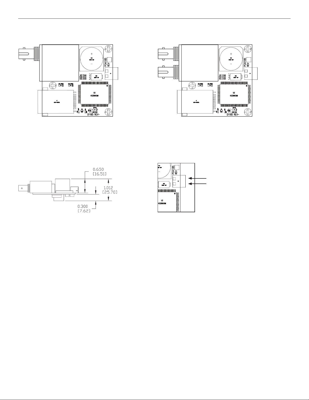
FIGURE 1 – TOP VIEW - 1 FIBER FIGURE 2 – TOP VIEW - 2 FIBER
FIGURE 3 – SIDE VIEW
OPTICS ARE SHOWN FOR BOARD ORIENTATION ONLY. ACTUAL OPTIC WILL VARY
DEPENDING ON SPECIFIC PRODUCT ORDERED.
FIGURE 4 – POWER CONNECTIONS
–
+
Power Supply:
22-27 VAC @ 100mA or
8-24 VDC @ 220 mA
TECH SUPPORT: 1.888.678.9427
INS_CNFE1(M,S)/(X)_REV–
05/26/11
PAGE 2
Page 3

INSTALLATION AND OPERATION MANUAL CNFE1(M,S)(1,2)(A,B)/(X)
WARNING: Unit is to be used with a Listed Class 2 power supply rated 22-27
VAC @ 100mA or 8-24 VDC @ 220 mA.
IMPORTANT SAFEGUARDS:
A) Elevated Operating Ambient - If installed in a closed or multi-unit rack
assembly, the operating ambient temperature of the rack environment may
be greater than room ambient. Therefore, consideration should be given to
installing the equipment in an environment compatible with the maximum
ambient temperature (Tma) specified by the manufacturer.
B) Reduced Air Flow - Installation of the equipment in a rack should be such
that the amount of air flow required for safe operation of the equipment is
not compromised.
The mounting holes are sized for a 2.5mm screw. Use an 8mm minimum long
standoff for mounting.
FIGURE A – DIMENSIONS
3 CORPORATE DRIVE | DANBURY, CT 06810 | USA
T: 203.796.5300 | F: 203.796.5303 | TECH SUPPORT: 1.888.678.9427 | INFO@ COMNET.NET
8 TURNBERRY PARK ROAD | GILDERSOME | MORLEY | LEEDS, UK LS27 7LE
T: +44 (0)113 307 6400 | F: +44 (0)113 253 7462 | INFO-EUROPE@COMNET.NET
© 2013 Communications Networks Corporation. All Rights Reserved. “ComNet” and the “ComNet Logo” are registered trademarks of Communication Networks, LLC.
INS_CNFE1(M,S)/(X)_REV–
05/26/11
PAGE 3
 Loading...