

Page 1
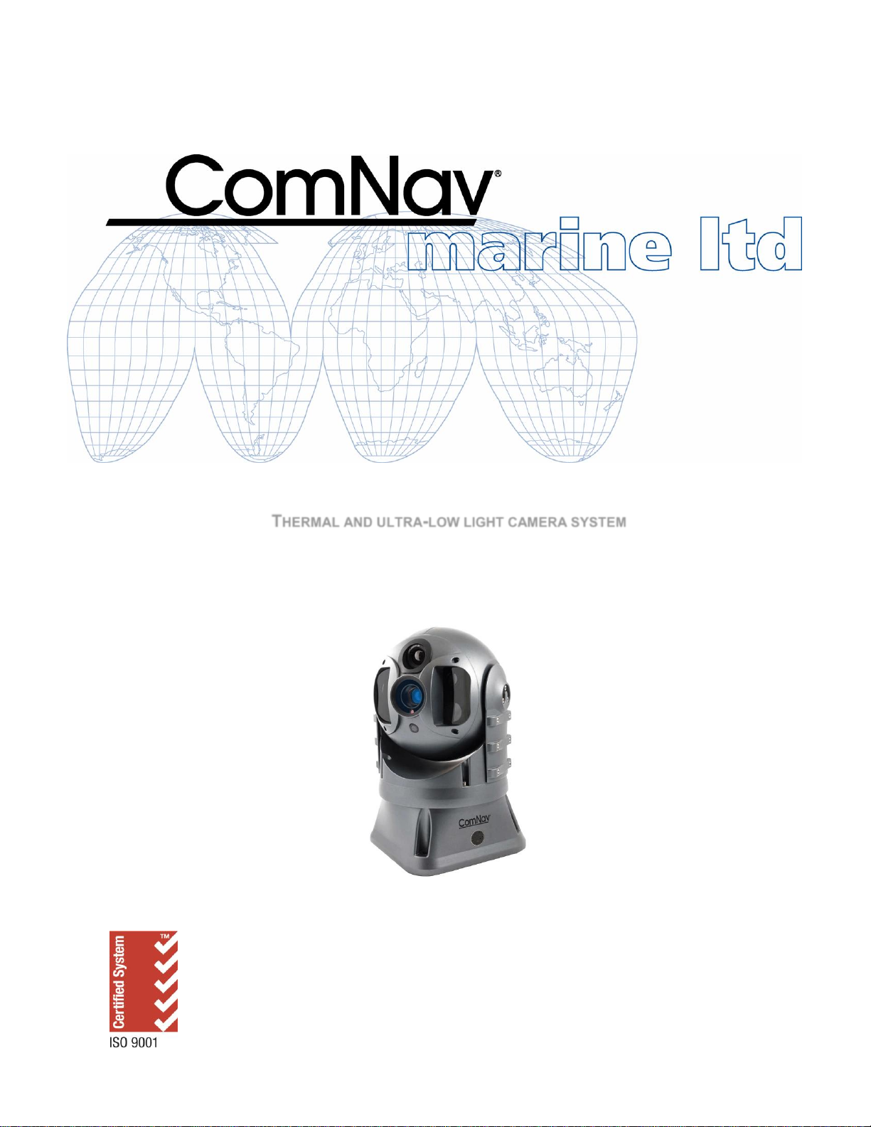
Installation & Operation Manual
V7
THERMAL AND ULTRA-LOW LIGHT CAMERA SYSTEM
PN 11610035 V1.0
Page 2

Page 3

ComNav V7 Installation & Operation
Welcome
Congratulations on your purchase of ComNav Marine Ltd. V7 Camera System. At ComNav
Marine Ltd., we are dedicated to reliability & quality in all our products, and the V7 camera
system is a good example of that. We promise to do our best to ensure your satisfaction with
your new V7 Camera System.
Warranty Notice
Prior to the installation and/or operation of the equipment, ensure that you read, understand,
and accept the conditions of the warranties as detailed in the Warranty Information section of
this manual.
General Notice
This document, ComNav part number 11610035 Version 1 Revision 0, is the approved
Installation and Operation Manual for use with V7 Camera System. Where versions of this
manual exist in other languages, the English version shall be considered authoritative.
Proprietary
Copyright
Special Note
The data in this publication shall not be disclosed without permission and shall not be
duplicated, used, or disclosed in whole or in part except to the extent provided in any
contract of which this document is made a part. This restriction does not limit the
customer’s right to use information contained in this document if it is obtainable from
another source without restriction. The data subject to this restriction are contained in all
sheets of this document and related drawings and document specifications herein. ComNav
reserves the right to make changes to its products or specifications at any time, without
notice, in order to improve design or performance and to reasonably supply the best possible
product.
Copyright © 2019 by ComNav Marine Ltd.. All rights reserved. This publication or any
parts thereof, may not be reproduced in any form without the express written permission
of ComNav Marine Ltd.
Please see Appendix 4 for ordering information of all available camera systems and
accessories.
WARNING: Thermal imaging systems are controlled by Canadian and International laws
and are subject to export controls. Please contact ComNav Marine Ltd. with any question
concerning export compliance for the application or geographic location of the installation
and/or use of this Thermal camera system.
Document PN 11610035 V1.0 - 1 -
Page 4

ComNav V7 Installation & Operation
There are various versions of this thermal camera system that are approved for international
distribution without the export control restrictions.
Please contact ComNav Marine Ltd. if you have any questions.
ComNav Marine Ltd.
#15 - 13511 Crestwood Place
Richmond, British Columbia
V6V 2G1, Canada
www.comnav.com
Document PN 11610035 V1.0 - 2 -
Page 5

ComNav V7 Installation & Operation
Revision
By
Description
1R0
AA
first release
Document History
Document PN 11610035 V1.0 - 3 -
Page 6

ComNav V7 Installation & Operation
About this Manual
This manual provides essential information for the safe and reliable operation of the ComNav
V7 Camera System. Read this manual in its entirety before using the Camera System for the
first time. Keep the manual handy until you become thoroughly familiar with the operation of
the camera system.
Manual Format
This manual has been formatted to be printed on both sides of a standard Letter sized paper
(8.5” x 11”).
If you have obtained this manual as a soft-copy, please note that it is in Adobe® Portable
Document Format (“PDF”), and may be viewed & printed with Adobe Reader®, or compatible
PDF-format viewers.
When printing this manual, select “duplex printing” (or the equivalent term used by your
printer’s software driver), in order to print it in a double-sided format. If your printer does not
have built-in duplexing capability, you can still print this manual double-sided by following the
instructions that came with your printer for doing “hand duplexing”.
You should also select the Auto-Rotate and Centre option in the Print Dialog box, de-select
the Choose Paper Source by PDF page size option. Set Page Scaling to None – Reader’s
Default setting is Shrink to Printable Area, and is printer-dependant (usually set at ~97%), but
it is not needed in this instance.
Document PN 11610035 V1.0 - 4 -
Page 7

ComNav V7 Installation & Operation
Table of Contents
Welcome ___________________________________________________________________________ 1
Warranty Notice ......................................................................................................................................................... 1
General Notice ........................................................................................................................................................... 1
Proprietary ................................................................................................................................................................. 1
Copyright ................................................................................................................................................................... 1
Special Note .............................................................................................................................................................. 1
Document History ...................................................................................................................................................... 3
About this Manual ...................................................................................................................................................... 4
Manual Format .......................................................................................................................................................... 4
Table of Contents ___________________________________________________________________ 5
List of Figures ............................................................................................................................................................ 7
List of Tables ............................................................................................................................................................. 7
When You Open the Box _____________________________________________________________ 10
Camera Package Contents ................................................................................................................................. 10
Safety Notes! ______________________________________________________________________ 11
System Introduction ________________________________________________________________ 13
V7 Camera System ................................................................................................................................................. 13
Pan-Tilt-Zoom Control ......................................................................................................................................... 13
Joystick/Keypad Controller ...................................................................................................................................... 14
Operation _________________________________________________________________________ 18
On Screen Display Symbols .................................................................................................................................... 18
Real-time data description ................................................................................................................................... 19
Visible Light Camera ICON.................................................................................................................................. 19
Thermal Camera ICON ........................................................................................................................................ 19
Picture In Picture (PIP) ICON .............................................................................................................................. 19
Parallel View ICON ................................ ................................ .............................................................................. 19
Functions ICON ................................................................................................................................................... 20
Video Adjustment ICON ...................................................................................................................................... 20
Photo Archive ICON ............................................................................................................................................ 21
Video Archive ICON ............................................................................................................................................ 21
External Power and UPS battery Status ICON .................................................................................................... 21
Telemetery/diagnose/settings ICON ................................................................ .................................................... 22
Thermal Camera menu ............................................................................................................................................ 22
White Hot ICON ................................................................................................................................................... 22
Black Hot ICON ................................ ................................................................ ................................ ................... 22
Gain+ ICON ......................................................................................................................................................... 22
Gain- ICON .......................................................................................................................................................... 22
Restore Default Parameter ICON ........................................................................................................................ 23
LUM+ ICON ......................................................................................................................................................... 23
LUM- ICON .......................................................................................................................................................... 23
Human Search ..................................................................................................................................................... 23
Colour Palette ...................................................................................................................................................... 23
Zoom Feature .......................................................................................................................................................... 24
The Telemetry/Diagnose/setting .............................................................................................................................. 26
Document PN 11610035 V1.0 - 5 -
Page 8

ComNav V7 Installation & Operation
Care & Maintenance ________________________________________________________________ 32
Warning ................................................................................................................................................................ .... 32
Protection of Wires and Cabling ............................................................................................................................... 32
Periodic Checks ....................................................................................................................................................... 32
General Precautions................................................................................................................................................. 32
Repair ....................................................................................................................................................................... 32
Fuse Replacement ................................................................................................................................................... 32
Cleaning ................................................................................................................................................................... 33
UPS and CPU Batteries ........................................................................................................................................... 33
Appendix 1 ________________________________________________________________________ 36
Specifications ........................................................................................................................................................... 36
Thermal Camera .............................................................................................................................................. 36
Ultra-Low Lux Camera ..................................................................................................................................... 37
Light Intensifier Camera ................................................................................................................................... 37
General Technical Specification ....................................................................................................................... 37
Power ............................................................................................................................................................... 38
Mechanical ....................................................................................................................................................... 38
Appendix 2 ________________________________________________________________________ 39
Mechanical Specifications ........................................................................................................................................ 39
Appendix 3 ________________________________________________________________________ 40
Installation ................................................................................................................................................................ 40
Appendix 4 ________________________________________________________________________ 41
Ordering Information ................................................................................................................................................ 41
Appendix 5 ________________________________________________________________________ 42
Troubleshooting ....................................................................................................................................................... 42
Unresponsive Video Output ............................................................................................................................. 42
Thermal Image appearing as too dark or too bright.......................................................................................... 42
Sunrise or sunset exposure .............................................................................................................................. 42
Warranty Information _______________________________________________________________ 43
User Notes ________________________________________________________________________ 47
Document PN 11610035 V1.0 - 6 -
Page 9

ComNav V7 Installation & Operation
List of Figures
Figure 1 – Various Camera Systems Setup. ....................................................................................................................... 13
Figure 2 – Joystick/keypad Controller. ................................................................................................................................. 14
Figure 3 – Joystick Controller. ............................................................................................................................................. 18
Figure 4 – Camera Startup Screen. ................................................................................................................................ ..... 18
Figure 5 – Parallel View. ...................................................................................................................................................... 20
Figure 6 – Battery Status. .................................................................................................................................................... 21
Figure 7 – Colour palette menu options. .............................................................................................................................. 24
Figure 8 – Colour Camera Zoom Feature. ........................................................................................................................... 24
Figure 9 – Thermal Camera Zoom feature. ......................................................................................................................... 25
Figure 10 – Telemetry Panel. .............................................................................................................................................. 26
Figure 11 – Motor tab options. ............................................................................................................................................. 27
Figure 12 – Photosensor tab options. .................................................................................................................................. 27
Figure 13 – Gyroscope tab settings. .................................................................................................................................... 28
Figure 14 – Mechanical Drawing specification..................................................................................................................... 39
Figure 15 – Wiring of the V7 Camera. ................................................................................................................................. 40
List of Tables
Table 1 – V7 Camera Box Content. ................................................................................................................................ ..... 10
Table 2 – Thermal Camera System Specifications. ............................................................................................................. 36
Table 3 – Ultra-low Lux Camera Specifications. .................................................................................................................. 37
Table 4 – Light Intensifier Camera Specifications. ............................................................................................................... 37
Table 5 – General Specifications. ........................................................................................................................................ 37
Table 6 – Power Specifications. .......................................................................................................................................... 38
Table 7 – Mechanical Specifications. .................................................................................................................................. 38
Table 8 – Order Information................................................................................................................................................. 41
Document PN 11610035 V1.0 - 7 -
Page 10

ComNav V7 Installation & Operation
Introduction
Document PN 11610035 V1.0 - 8 -
Page 11

ComNav V7 Installation & Operation
Document PN 11610035 V1.0 - 9 -
Page 12
ComNav V7 Installation & Operation Introduction
Item
Part #
Description
Quantity
1
11610035
V7 Camera and Joystick Controller
1
2
29010108
Installation / Operating Manual
1
When You Open the Box
Check that the packaging and the contents are not visibly damaged.
Contact your supplier immediately if any of the parts listed below are missing or damaged
Camera Package Contents
Table 1 – V7 Camera Box Content.
Document PN 11610035 V1.0 - 10 -
Page 13

ComNav V7 Installation & Operation Introduction
Safety Notes!
The following important notes must be followed carefully to run the camera and respective accessories
such as keypad controllers etc. The camera and accessories are referred to as ‘Camera system’
hereafter in this document.
The V7 Imaging camera is designed to be used in conjunction with other navigational aids and
should not be used as the sole or primary navigation device.
Certain Thermal Imaging Camera models cannot be exported to various territories without
specific Export Licenses which must be obtained from the relevant trade and industry bodies
prior to exportation. Failure to observe strict import and export regulations is a serious
offense. Ensure the correct licenses are obtained where necessary. For further information
contact your Comnav dealer or Comnav support. Contact details can be found within this
document.
Before installing the camera, please read this manual carefully. During installation follow the
instructions indicated in this manual. Please keep this manual safe for future reference. An up to
date copy is available on our website: www.comnav.com
The installation of the Camera system including this camera and any associated accessories,
should be carried out by qualified service personnel or system installers in accordance with local
regulations.
Before powering the camera please check the supply voltage and ensure the power supply is safely
isolated using an appropriately rated fuse or circuit breaker. Verify that the supply power is within
acceptable range (See Appendix).
Please ensure the power, video and data umbilical are stowed safely and that terminations to third
party hardware or extension cables are properly shielded from moisture.
Do not operate and store the camera beyond the specified temperatures and humidity limits.
To prevent electric shock and/or to not void the warranty, never remove the screws or the cover of
the camera. There are no user serviceable parts within the camera housing. Refer to qualified and
approved Comnav service personnel for servicing.
Never aim the camera at the sun or other extremely bright objects
Do not manually or forcefully move the camera even when it is not powered
Document PN 11610035 V1.0 - 11 -
Page 14

ComNav V7 Installation & Operation Introduction
Document PN 11610035 V1.0 - 12 -
Page 15
ComNav V7 Installation & Operation Introduction
System Introduction
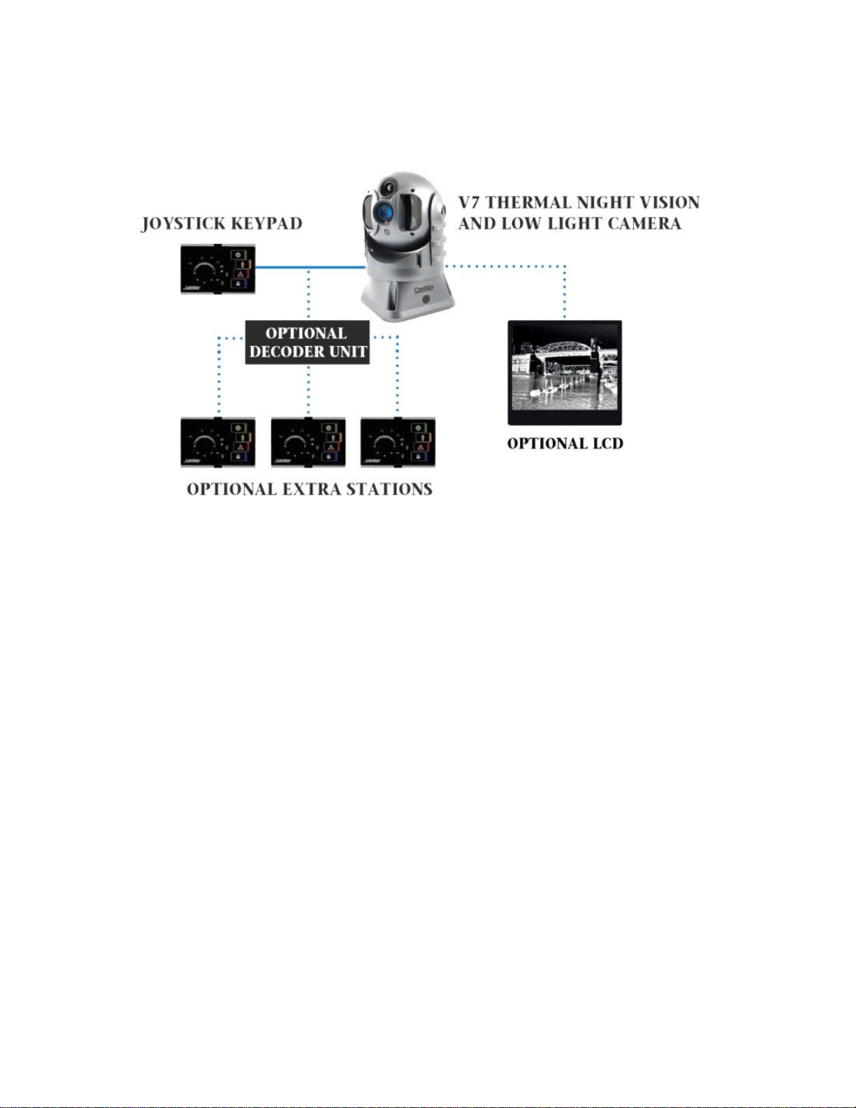
Figure 1 – Various Camera Systems Setup.
V7 Camera System
The V7 camera is equipped with four cameras, an ultra-sensitive thermal camera, two daylight
cameras, and a light intensifier camera, that are specifically designed for marine applications.
Unlike conventional cameras, Thermal Imaging cameras sense heat in the form of Infra Red (IR)
radiation given off by objects rather than amplifying ambient light. The thermal imager engine inside
the V7 is sensitive enough to detect temperature differences as low as 40mK. Cold objects such as ice
emits thermal energy in the long wave infrared spectrum sensed by the camera. Thermal Imaging
cameras process radiated, rather than reflected energy. Therefore, no source of illumination is
required.
The image intensifier camera provides superior picture quality for applications ranging from oil spillage
detection, marine security enforcement, and search and rescue missions.
A standard V7 camera system comes with a Joystick controller. Multiple cameras and multiple
controllers may be connected in one system by using a splitter switch accessory box (see Appendix 2
for ordering information).
Pan-Tilt-Zoom Control
The pan/tilt system can rotate the camera 360 continuously in both the horizontal and vertical planes.
The maximum turn rate is 100/s.
Document PN 11610035 V1.0 - 13 -
Page 16
ComNav V7 Installation & Operation Introduction
Joystick/Keypad Controller
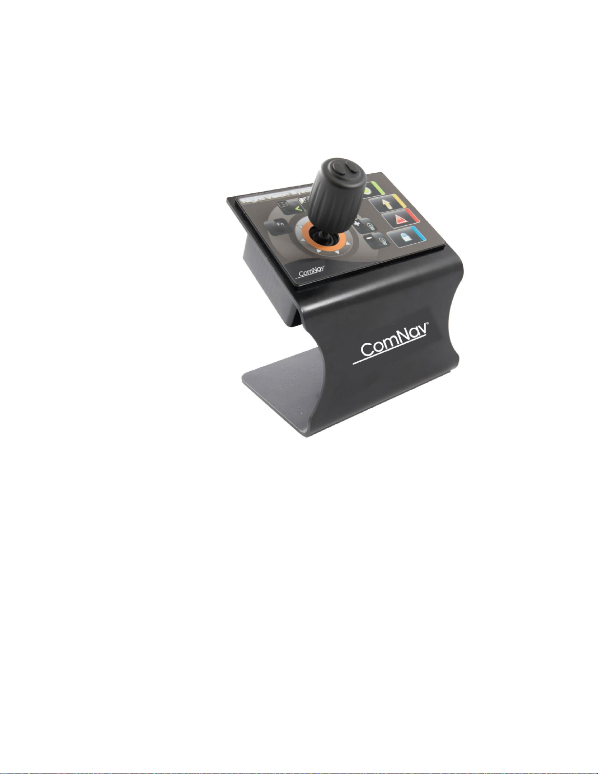
The Figure 2 shows the Joystick/Keypad controller which is the control unit of the V7 camera system.
It allows full access and control of all the camera’s features and menu setup.
Figure 2 – Joystick/keypad Controller.
Document PN 11610035 V1.0 - 14 -
Page 17

ComNav V7 Installation & Operation Introduction
Document PN 11610035 V1.0 - 15 -
Page 18

ComNav V7 Installation & Operation
Operation
Document PN 11610035 V1.0 - 16 -
Page 19

ComNav V7 Installation & Operation
Document PN 11610035 V1.0 - 17 -
Page 20
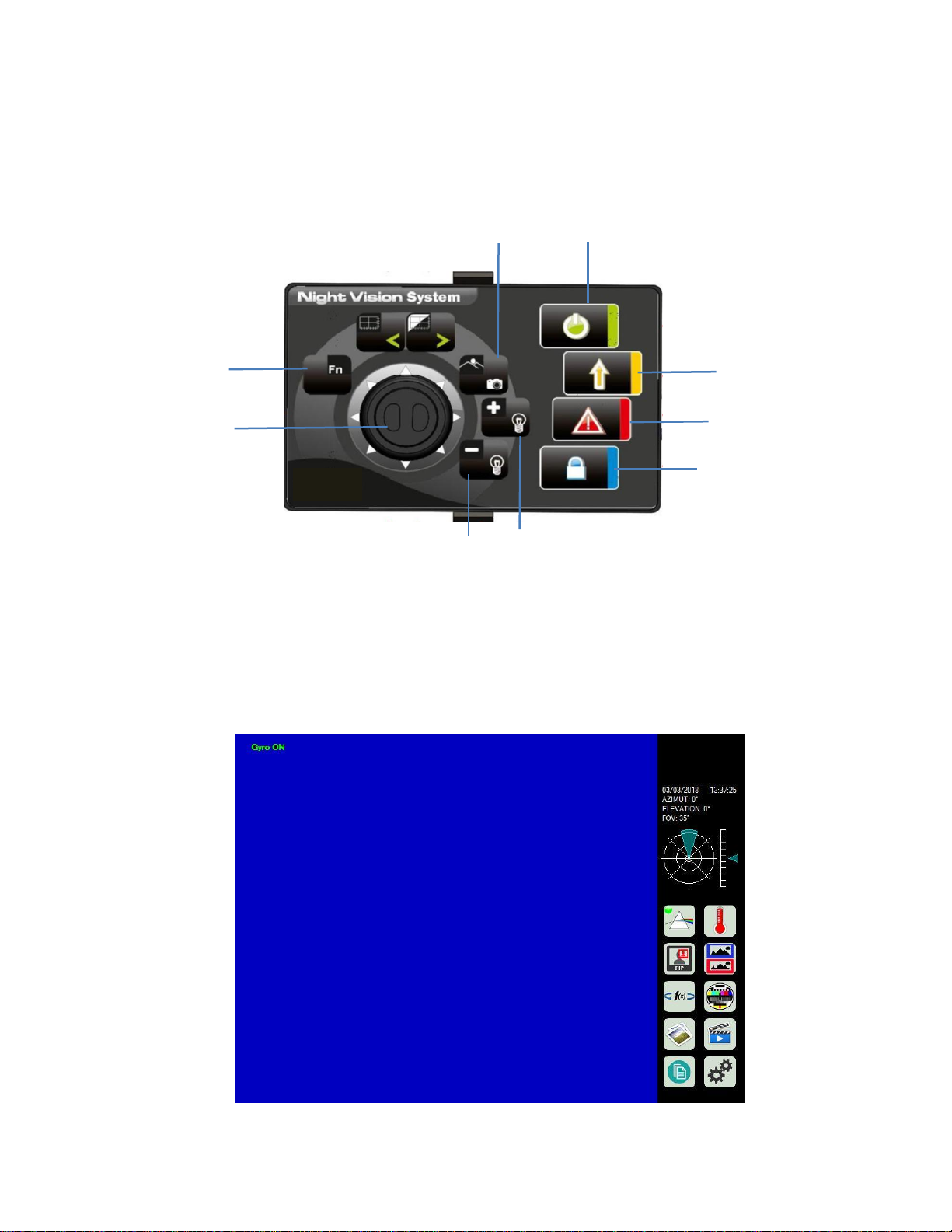
ComNav V7 Installation & Operation
Figure 4 – Camera Startup Screen.
Power Button
Screenshot
Button
Reset/Home
Button
Status/Alarm
Day/Night mode
Function Button
(for Images)
Joystick
Zoom In/Out
Brightness level
increase
Brightness level decrease
Operation
The Figure 3 shows the Joystick controller along with a description of the buttons function.
Figure 3 – Joystick Controller.
On Screen Display Symbols
Clicking the power button will display the Startup Screen shown in Figure 4, where the Left (shown in Blue)
portion displays the video feed while the right section shows different settings and relevant scene information
and icons. A description is shown below.
Document PN 11610035 V1.0 - 18 -
Page 21
ComNav V7 Installation & Operation
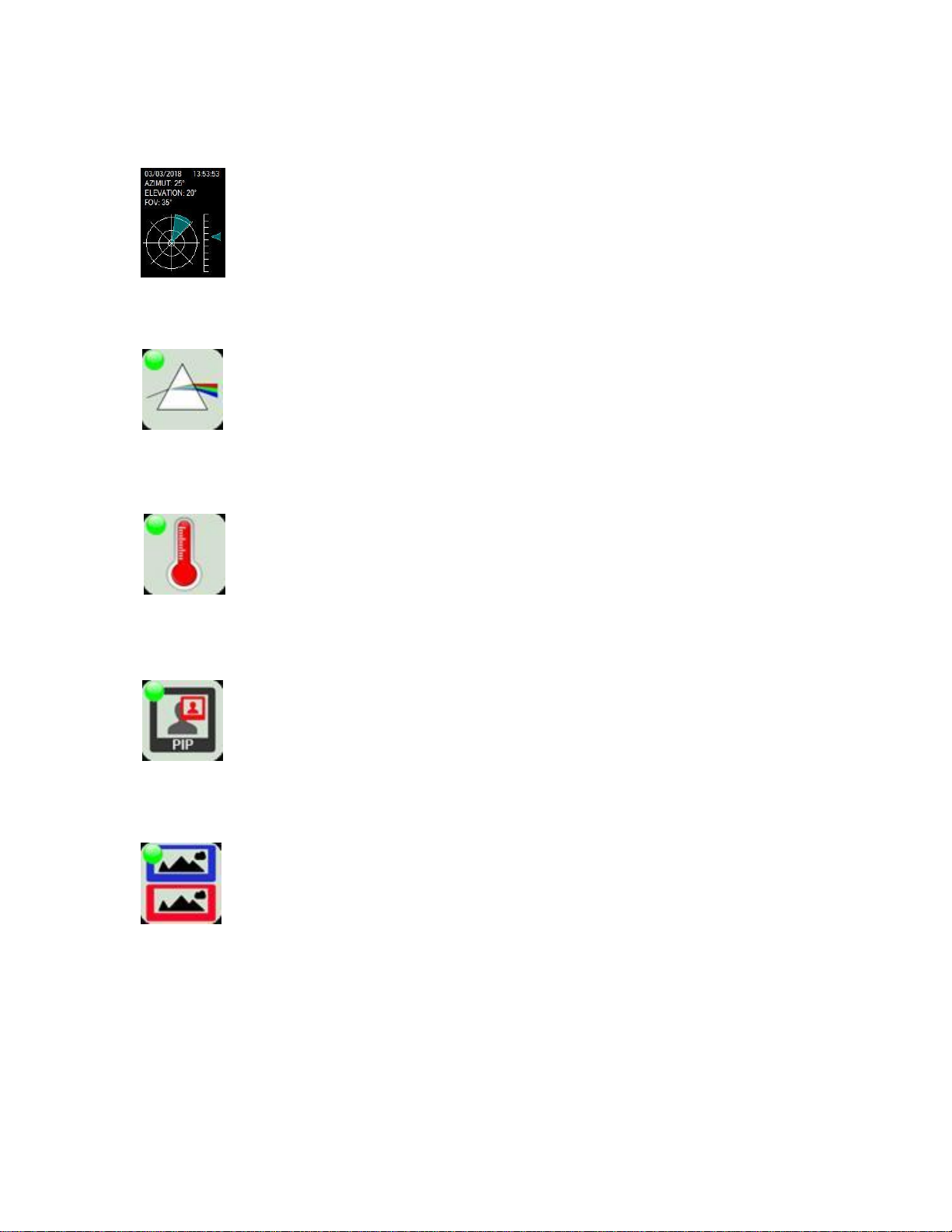
Real-time data description
Shows the date and time, azimuth and elevation angle the camera points at, as well as the
FOV of the active camera. The circular plot shown shows the horizontal FOV (azimuth) of
the active cameras, if more than one camera is active, then different FOVs will be overlaid
on the same plot each having a different colour.
The arrow shows the vertical positon (elevation) of the camera. When the visor is upside down, the arrow’s colour turns red, and a flashing red inscription displays the alarm status.
Visible Light Camera ICON
Click to manually activate the Ultra Low Lux Colour camera. The camera activates
automatically based on the ambient light level.
The green circle indicates that the camera is active.
Thermal Camera ICON
Click to activate the thermal camera. Click once again to change the thermal camera
settings. See Section Thermal Camera Menu for details.
Picture In Picture (PIP) ICON
Click the PIP ICON to activate the dual cameras (visible light camera and thermal camera).
Click the icon once again to deactivate the dual mode cameras and return to the single
mode camera.
Parallel View ICON
Click to activate the parallel vision mode which displays the visible light and thermal
cameras.
Document PN 11610035 V1.0 - 19 -
Page 22
ComNav V7 Installation & Operation
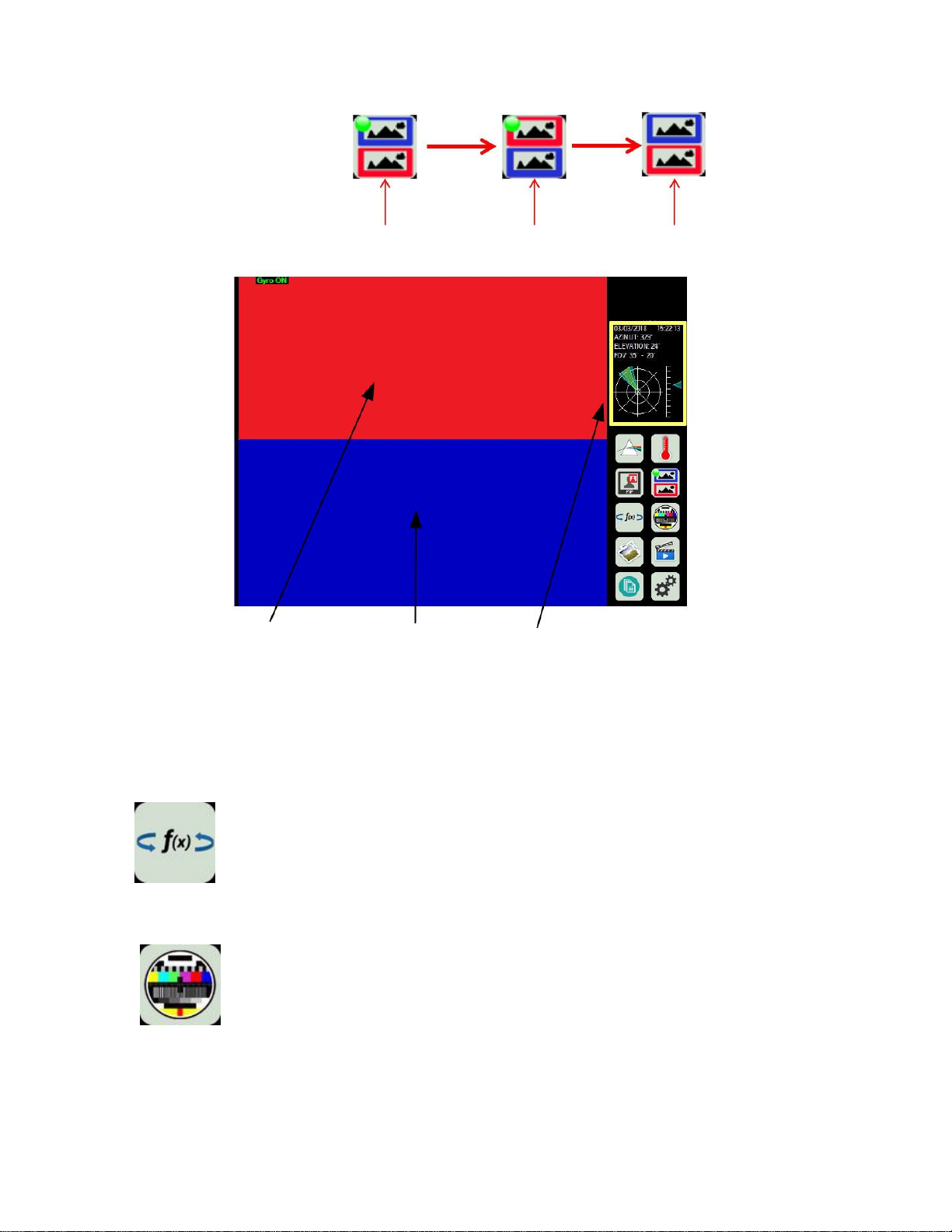
Figure 5 – Parallel View.
Thermal
image
Visible light
image
Two FOV are shown.
- Yellow represents the thermal camera
- Cyan/Blue for visible light camera
The Figure 5 shows the parallel view icon activated.
Functions ICON
Click to show the special functions menu. The menu shows the different slaving options
(radar and gyrocompass) as well as the video-tracking and gyro-stabilization options.
Video Adjustment ICON
Click on Icon to adjust the visible light camera video settings. The menu allows adjusting
the brightness, colour saturation, contrast, enable/disable greysacle vision and invert
colours. A restore button is available to restore the above menu items to default settings.
Document PN 11610035 V1.0 - 20 -
Page 23
ComNav V7 Installation & Operation
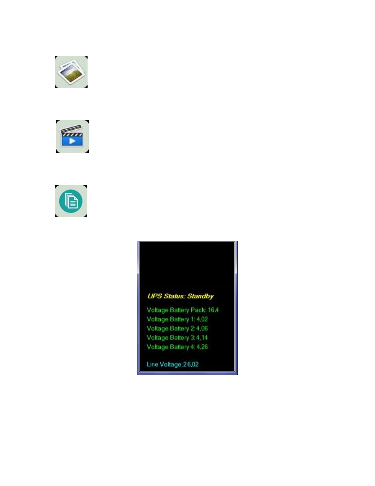
Figure 6 – Battery Status.
Photo Archive ICON
Click to show archived photos. Files can be saved to a removable media, renamed or
deleted.
Video Archive ICON
Click to show archived videos. Files can be saved to a removable media, renamed or
deleted.
External Power and UPS battery Status ICON
The Icon shows the status of the external power and internal batteries.
The Interruptible Power Supply (UPS) status has three options:
- Standby: Refers to external power
- Battery Powered: Refers to battery power
- Charge: Refers to external power and charging of the internal batteries
An example of battery status is shown in Figure 6. The UPS status is shown as standby.
Document PN 11610035 V1.0 - 21 -
Page 24
ComNav V7 Installation & Operation
Telemetery/diagnose/settings ICON
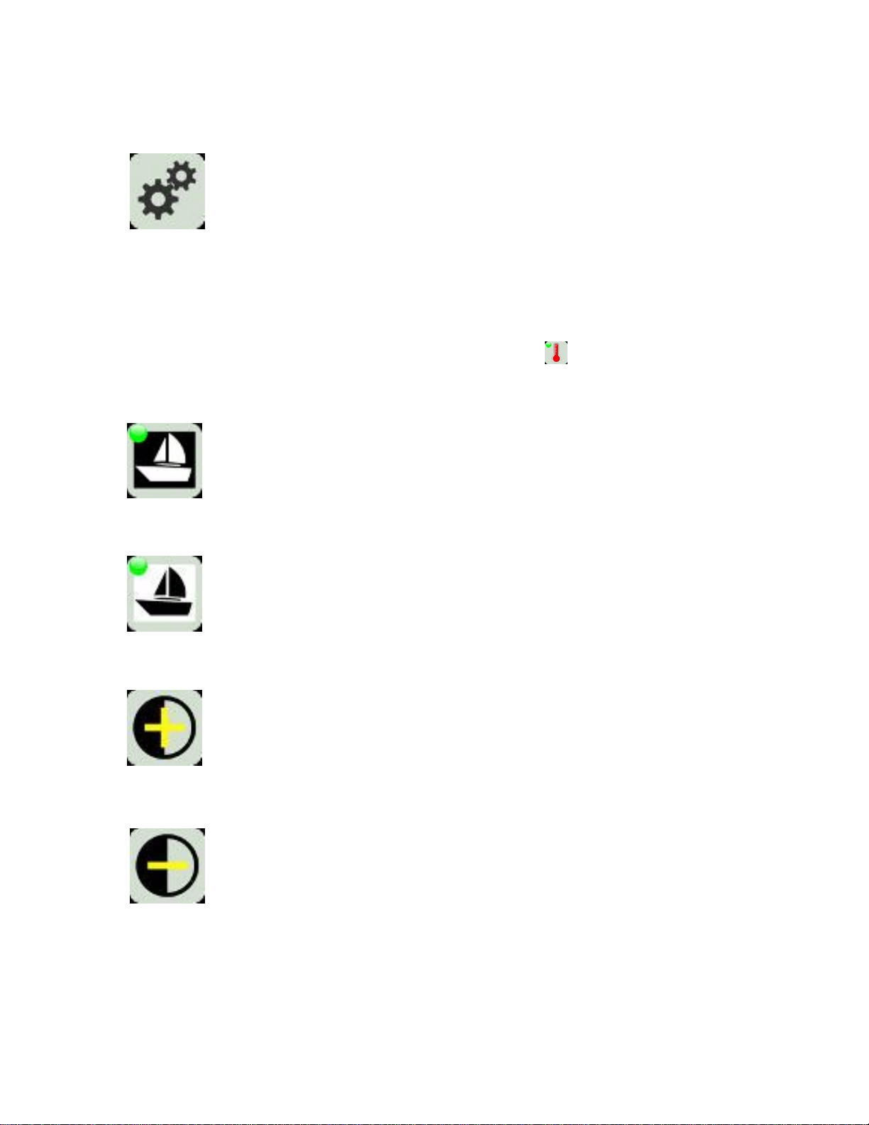
Click to show the Telemetry menu. Requires password to modify camera settings.
Thermal Camera menu
The following icons represents the Thermal camera icon submenu options.
White Hot ICON
Show Hot objects in the scene in WHITE.
Black Hot ICON
Show Hot objects in the scene in BLACK.
Gain+ ICON
Click to increase the scene contrast.
Gain- ICON
Click to decrease the scene contrast.
j
Document PN 11610035 V1.0 - 22 -
Page 25
ComNav V7 Installation & Operation
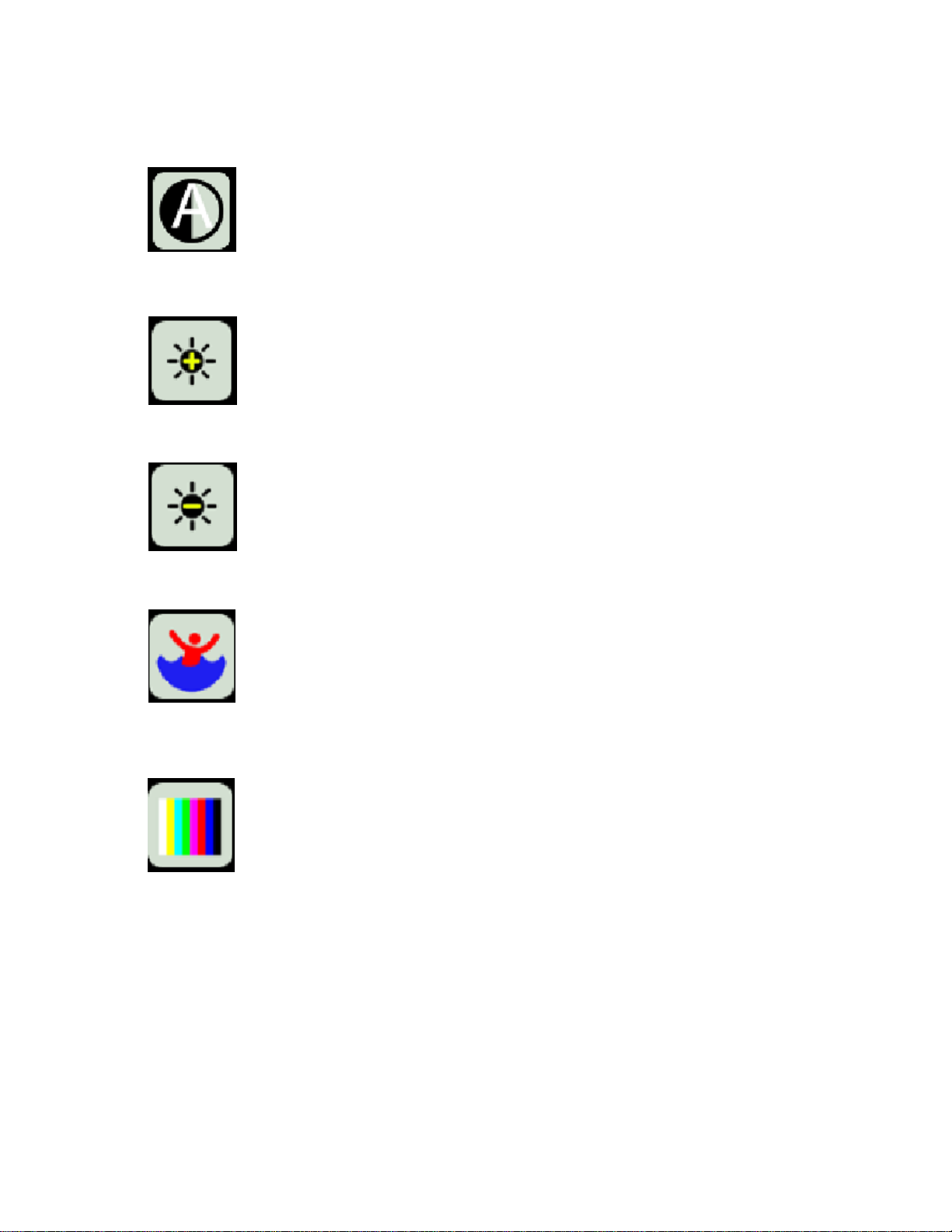
Restore Default Parameter ICON
Click on Icon to restore default parameters.
LUM+ ICON
Click to increase luminosity.
LUM- ICON
Click to decrease luminosity.
Human Search
Colour Palette
Activate the human search.
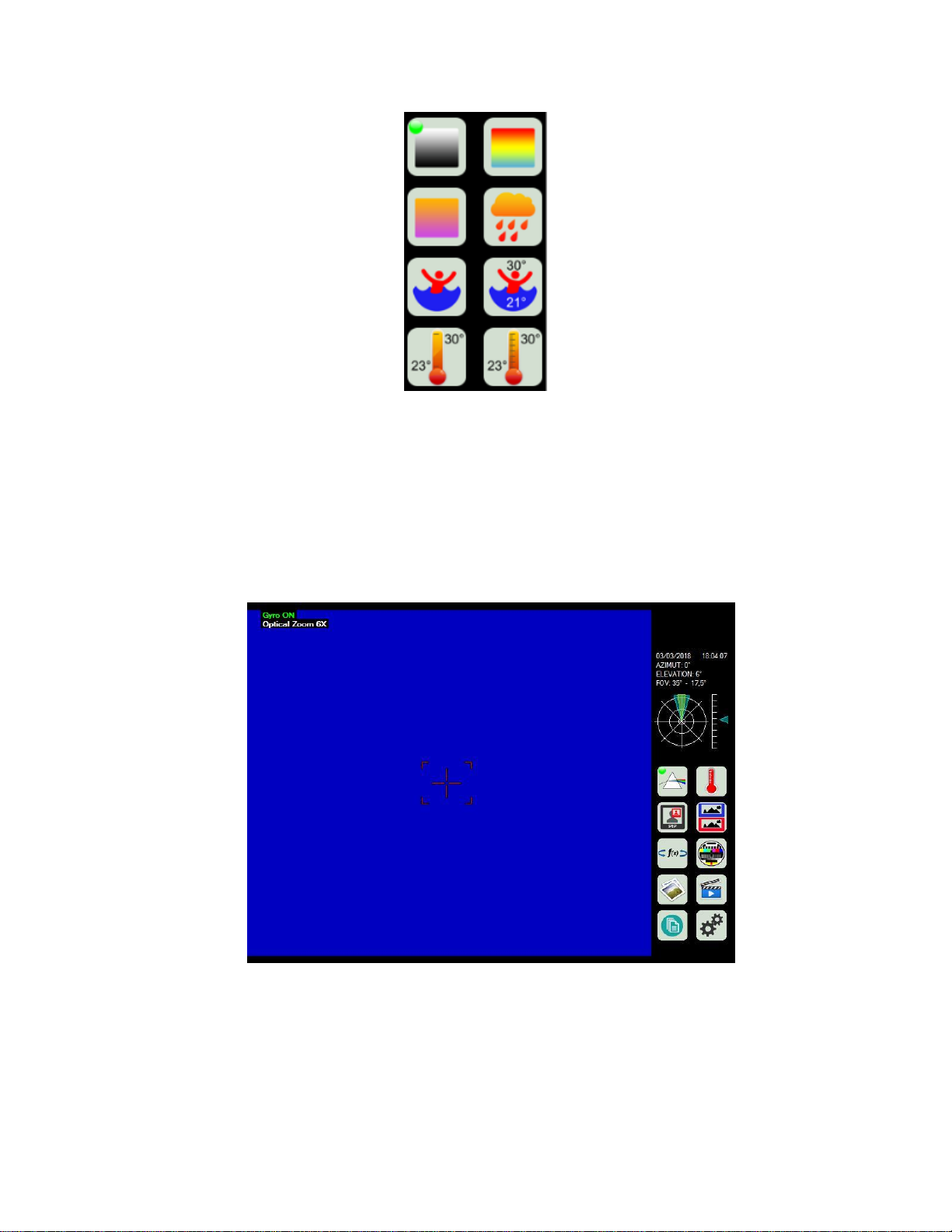
Sets the colour palette. Opens the palette shown in Figure 7.
Document PN 11610035 V1.0 - 23 -
Page 26
ComNav V7 Installation & Operation
Figure 7 – Colour palette menu options.
Figure 8 – Colour Camera Zoom Feature.
Zoom Feature
The Figure 8 shows that the Ultra Low Lux Colour camera is active (indicated by the green circle in the visible
daylight camera ICON), and the Zoom is active (Indicated in the top left hand corner of Figure 8 by “Optical Zoom
6X”). The optical zoom can be further increased/decreased by rotating the knob of the Joystick in Figure 3
clockwise/counter-clockwise respectively.
Document PN 11610035 V1.0 - 24 -
Page 27
ComNav V7 Installation & Operation
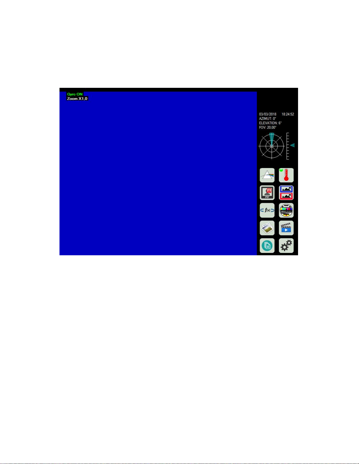
Figure 9 – Thermal Camera Zoom feature.
The Figure 9 shows that the Thermal camera is active (indicated by the green circle in the Thermal camera
ICON), and the Zoom is active (Indicated in the top left hand corner of Figure 9 by “Zoom X1.0”). The zoom can
be further increased/decreased by rotating the knob of the Joystick in Figure 3 clockwise/counter-clockwise
respectively.
Document PN 11610035 V1.0 - 25 -
Page 28
ComNav V7 Installation & Operation
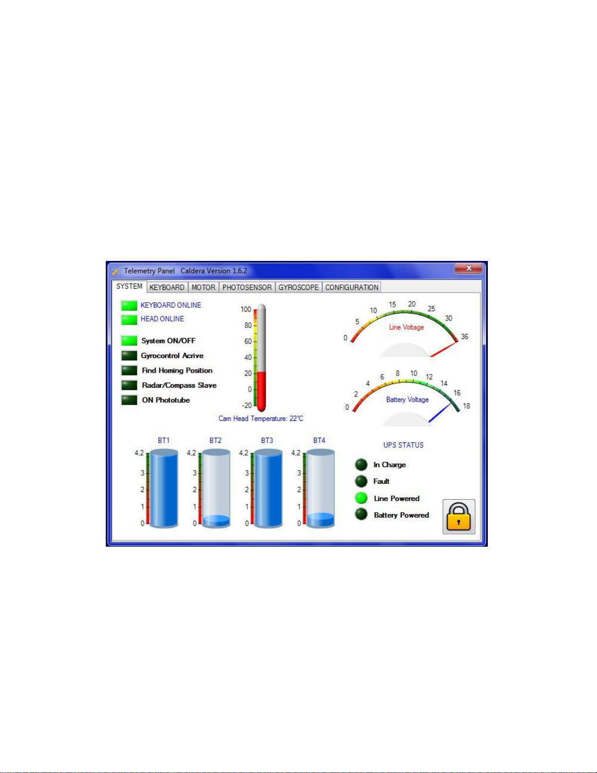
Figure 10 – Telemetry Panel.
The Telemetry/Diagnose/setting
The Figure 10 shows the Telemetry Panel Settings having six tabs: System, Keyboard, Motor, Photosensor,
Gyroscope and Configuration. A description of each of the tabs is as follows:
System Tab shows the system status.
Keyboard Tab shows the status of the Keyboard and Joystick.
Motor Tab shows the pan/tilt motor status and reset parameter (see Figure 11).
Photosensor Tab shows the photosensor value versus brightness. Allows setting the
activation/deactivation values of the daylight camera (see Figure 12).
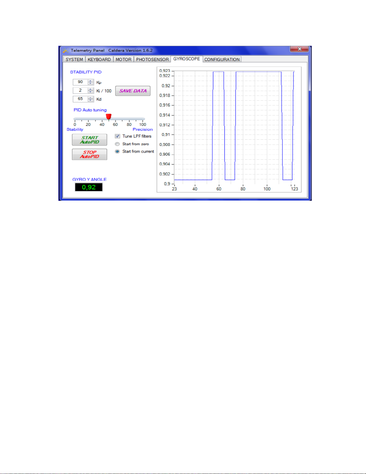
Gyroscope Tab tunes the Gyroscope filter parameters for optimal performance (see Figure 13).
Configuration Tab configures the system.
Document PN 11610035 V1.0 - 26 -
Page 29

ComNav V7 Installation & Operation
Figure 11 – Motor tab options.
Figure 12 – Photosensor tab options.
Document PN 11610035 V1.0 - 27 -
Page 30
ComNav V7 Installation & Operation
Figure 13 – Gyroscope tab settings.
Document PN 11610035 V1.0 - 28 -
Page 31

ComNav V7 Installation & Operation
Document PN 11610035 V1.0 - 29 -
Page 32

ComNav V7 Installation & Operation
Care & Maintenance
Document PN 11610035 V1.0 - 30 -
Page 33

ComNav V7 Installation & Operation
Document PN 11610035 V1.0 - 31 -
Page 34

ComNav V7 Installation & Operation
Care & Maintenance
The V7 Camera System has been designed to provide many years of reliable service. The
following care and maintenance tips will help to ensure the longevity of the equipment.
Warning
Do not rotate the sensor using your hand.
Do not point the camera directly towards the Sun.
Protection of Wires and Cabling
After installation, ensure that the system’s components are securely mounted and will not
shake loose with the vibrations that are expected in a marine vessel.
Ensure that the cables to the equipment are well secured with clamps and/or alternative
fasteners.
Many potential problems can be avoided by ensuring that cables and wiring do not cause any
connectors strain.
Periodic Checks
After the first six months of operation, a thorough examination of the entire Camera system
MUST BE UNDERTAKEN. Verify that all electrical connections, cables, clamps, mounting
brackets, and mechanical connections are secure.
An annual inspection should be undertaken thereafter.
General Precautions
A few precautions will keep the unit in prime condition:
The Camera and control enclosures do not require any special maintenance. An
Avoid exposing the enclosure to solvents, acids, and bases – some of which may
Disable the camera motion before cleaning to prevent pinch-point hazard.
The Camera and control enclosures are designed to be weatherproof and splash
Avoid operating the camera in environments exceeding a temperature of 60°C or
Repair
There are no user serviceable parts inside the Camera or controller enclosures. Should the
unit become damaged in any way, Contact an authorized ComNav dealer.
Fuse Replacement
There are no fuses used inside the camera or controller unit. However, it is strongly
recommended that a fuse (or circuit breaker) be used when installing the equipment.
occasional cleaning is suggested; use a damp cloth and mild soap.
Note: Do not use abrasive cleaners or chemicals. Improper
Care can cause damage to the lens cover coating, degrade the
camera’s performance and may void the warranty.
damage the device.
resistant. Do not immerse in water.
below -20°C.
Note: If the fuse/breaker blows, determine the cause before
replacing or resetting
Document PN 11610035 V1.0 - 32 -
Page 35

ComNav V7 Installation & Operation
Cleaning
Clean the camera window only with low-pressure fresh water and a soft cloth. For water
spots, wipe the lens cover with a clean, fresh water dampened lens cloth.
UPS and CPU Batteries
UPS batteries must be replaced every two years, while Control CPU batteries must be
replaced every four years.
Document PN 11610035 V1.0 - 33 -
Page 36

ComNav V7 Installation & Operation
Appendices
Document PN 11610035 V1.0 - 34 -
Page 37

ComNav V7 Installation & Operation
Document PN 11610035 V1.0 - 35 -
Page 38

ComNav V7 Installation & Operation Technical Specification
Parameter
Specification
Description
Quad Payload Thermal, Low light & Daylight Pack w/Joystick Controller (30 mm Lens, 100 Hz)
Field of View
(FOV)
250 horizontal, 190 Vertical (@ wide zoom)
Sensor
Silicon CMOS Uncooled Microbolometer Chip
Resolution
640 x 480 – 307200 Pixel – 17 µm pitch
NETD
<40 mK @ whole band
Spectral
Response
7 - 14 µm
Focal Length
25/35 mm
Lens Type
Athermalized – Diamond Surface Coating Treatment
Zoom
Ultra Digital ≤ 8x
Frame
Technology
Shutterless
Frame Rate
30 – 100 FPS
Detection
Range
1 km – Human; 3 km – Vehicle/Vessel @ 25 mm Focal Length
Human Target
1 km
DSP
DSP CALDERATM
Video Refresh
Rate
50 – 60 Hz
Image
Processing
Video Grabbing, Recording, Multiview Real Time, PIP, Video-analysis
Appendix 1
Specifications
Thermal Camera
Table 2 – Thermal Camera System Specifications.
Document PN 11610035 V1.0 - 36 -
Page 39

ComNav V7 Installation & Operation Technical Specification
Parameter
Specification
Number of Cameras
2
Type
Ultra-Low Lux Colour Camera
Sensitivity
0.01 Lux @ Colour
Field of View (FOV)
30° x 30° (@ wide zoom)
Sensor
SuperChip II SSNR III Starlight
Sensor Resolution
1000 lines
Window Type
Self-Cleaning Photocatalytic glass
Optical Zoom
≤ 30X1
Digital Zoom
Combined 40X
Parameter
Specification
Sensor
SuperGen Intensifier Electron Tube SSNR
Field of View (FOV)
30° Horizontal, 30° Vertical
Spectral Range
200 – 900 nm
Resolution
> 60 plmm
Window Type
Electron Beam Treated Sapphire Glass
Parameter
Specification
Interfaces
NMEA 0183 for Gyro Compass Slaving and
Radar Slaving (both Optional)
Video Output
DVI/VGA/HDMI/Composite Signal
Gyro Stabilization
2-axis Electro-Mechanical sensor coupled with
Digital Image Stabilization
Pan/Tilt Range
360°
Pan/Tilt Speed
0 – 100°/s
Ultra-Low Lux Camera
Table 3 – Ultra-low Lux Camera Specifications.
Light Intensifier Camera
Table 4 – Light Intensifier Camera Specifications.
1
Specification subject to change without notice.
General Technical Specification
Table 5 – General Specifications.
Document PN 11610035 V1.0 - 37 -
Page 40

ComNav V7 Installation & Operation Technical Specification
Parameter
Specification
Supply Voltage
9 – 24 VDC
Power Consumption
50 W
Parameter
Specification
Camera Dimension
180 x 180 x 310 mm
Camera Weight
4.9 kg
Jostick Keypad
Dimension
16 cm x 12 cm
6.1in x 4.5 in
Enclosure Rating
IP 68
External Enclosure
Material
Metallic – High Strength Aluminium Alloy
Anti-Corrosion
Treatment
Ultra-High Deep Anodization Treatment 30µ
Operating
Temperature
-20°C to +60°C
Storage Temperature
-50°C to +80°C
Auto Window Defrost
Self-cleaning Windows, with Electron Beam
Surface Treatment
Table 7 – Mechanical Specifications.
Power
Table 6 – Power Specifications.
Mechanical
.
Document PN 11610035 V1.0 - 38 -
Page 41
ComNav V7 Installation & Operation Technical Specification
Appendix 2
Mechanical Specifications
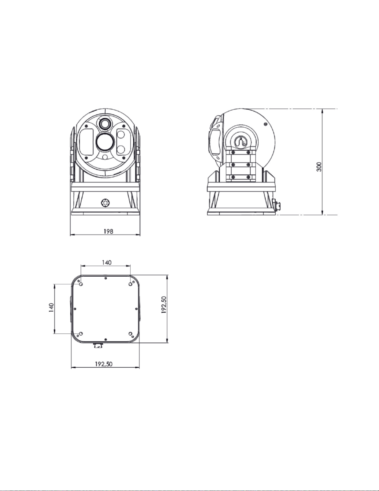
The Figure 14 shows the dimensions of the V7 Camera. It is advisable to mount the camera on a shock
absorber.
Figure 14 – Mechanical Drawing specification.
Document PN 11610035 V1.0 - 39 -
Page 42
ComNav V7 Installation & Operation Technical Specification
Appendix 3
Installation
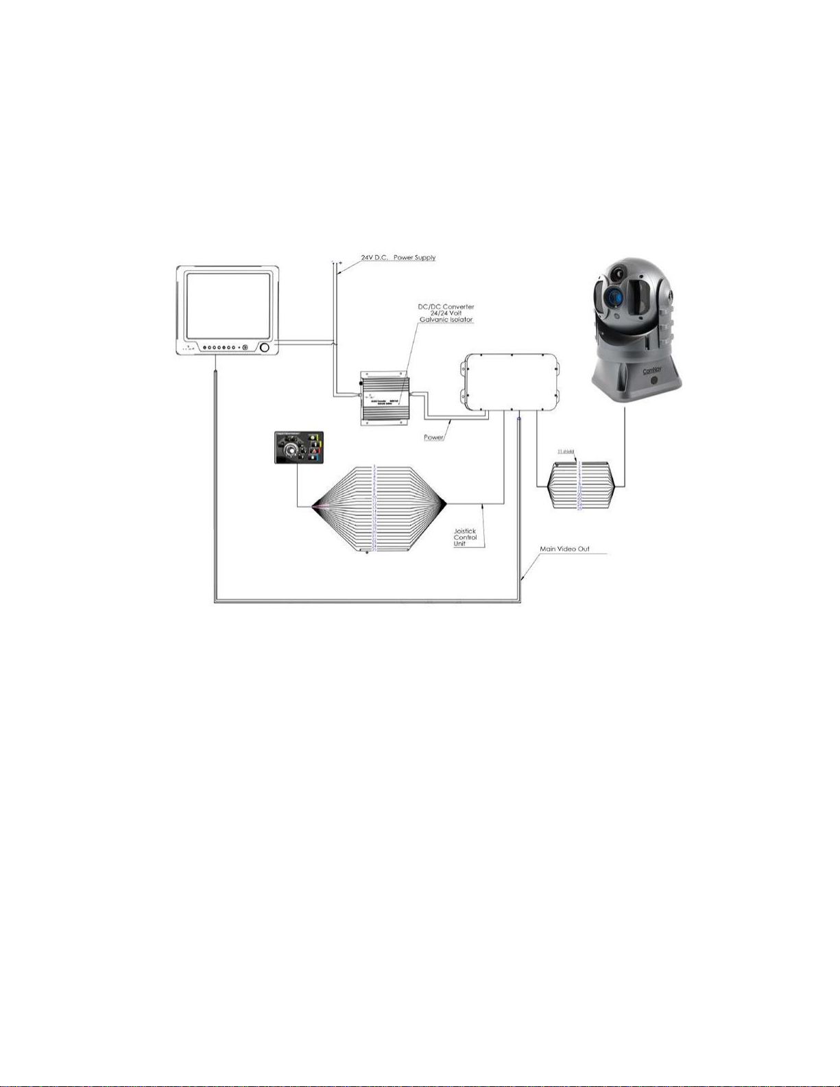
The Figure 15 shows the wiring connections of the V7 camera, Joystick, and touch monitor to
the control box and to the power supply.
Figure 15 – Wiring of the V7 Camera.
Document PN 11610035 V1.0 - 40 -
Page 43

ComNav V7 Installation & Operation Technical Specification
Part #
V7 GYRO STABILIZED CAMERA
11610035
V7 Quad Payload Thermal, Low-light & Daylight Pack w/Joystick Controller (30 mm Lens, 100
Hz)
V7 ACCESSORIES
31610068
30FT Extension Video Cable
21610033
Second Station Joystick Controller
21610034
Second Station Touchpad Controller
31610067
Shock Absorber
31610027
7’’ Combined Waterproof Monitor/4 Channel Quad Splitter
31610029
4 Channel Digital Video Recorder, 120 GB
31610030
8 Channel Digital Video Recorder, 160 GB
31610061
Universal Multi-Function Display Interface
31610031
Video Distribution Amplifier/1 Input to 4 Output
29010108
Installation & Operation Manual
Appendix 4
Ordering Information
Table 8 – Order Information.
Document PN 11610035 V1.0 - 41 -
Page 44

ComNav V7 Installation & Operation Troubleshooting
Appendix 5
Troubleshooting
Unresponsive Video Output
If the video output is too slow or corrupted, press the power button on the Joystick to turn off the
system. If the problem is not resolved by the prior step, press the power button once again on the
Joystick to turn off the system, and disconnect the power from the Control-box and wait for 30
seconds before connecting the power again, and powering the system by pressing the power
button on the Joystick.
Thermal Image appearing as too dark or too bright
The brightness of the scene is set automatically by the camera. However, in some special cases,
manual adjustment may be required. It is advisable to align the camera horizontally.
Sunrise or sunset exposure
During sunrise or sunset the Sun may appear in the camera’s field of view. While this setting is not
recommended, the Sun will not permanently damage the camera’s sensor. Some image artifacts
may develop as a result that will eventually be corrected by the image sensor. The longer the
exposure to the Sun, the longer the recovery time will be.
Document PN 11610035 V1.0 - 42 -
Page 45

ComNav V7 Installation & Operation Warranty
Warranty Information
Limited Warranty
This Limited Warranty (the “Warranty”) covers all V Series Camera products & accessories
(the “Equipment”) sold by ComNav Marine Ltd. (“ComNav”).
LIMITED TWO YEAR WARRANTY
ComNav warrants to the Purchaser, provided that the recommended installation and
maintenance procedures set forth in the manual (the “Manual”) provided with the Equipment
have been followed, and subject always to the other provisions of this Warranty, that the
Equipment is free from defects in workmanship and materials under normal use and service
for a period of two (2) years from the date of purchase of the Equipment by the Purchaser.
EXCLUSIONS
This Limited Warranty is null and void if:
1. The serial number of the Equipment has been removed, altered or mutilated;
2. Any of the anti-tamper seals covering case-screw holes, or other mechanisms for opening
the Equipment’s case, have been removed, broken or otherwise tampered with;
3. There are any defects in it, or damages to it, caused by:
a. Faulty installation or hook-up of the Equipment;
b. Abuse, misuse, or any use of the Equipment in violation of the instructions set forth in
the Manual;
c. Shipping, alterations, or incorrect and/or unauthorized service;
d. Accident, exposure of the Equipment to excessive heat, fire, lightning or other electrical
discharge, or water immersion;
e. Water damage due to failure to fully fasten the plug connected into the equipment’s
power/signal receptacle;
f. Improper or inadequate ancillary or connected equipment.
OTHER LIMITATIONS AND EXCLUSIONS
1. The Equipment is not intended for primary navigation or for use in safety of life applications;
ComNav does not warrant or guarantee that the Equipment will perform in accordance with
the requirements of such usage;
2. ComNav reserves the right to modify the Equipment without any obligation to notify, supply
or install any improvements or alterations to existing Equipment.
NO OTHER WARRANTIES
THE FOREGOING WARRANTY IS EXCLUSIVE OF ALL OTHER WARRANTIES AND
CONDITIONS, WHETHER WRITTEN, ORAL OR IMPLIED, ARISING BY STATUTE OR
OTHERWISE, WITH RESPECT TO THE DESIGN, SALE, INSTALLATION OR USE OF THE
Document PN 11610035 V1.0 - 43 -
Page 46

ComNav V7 Installation & Operation Warranty
EQUIPMENT, INCLUDING BUT NOT LIMITED TO IMPLIED WARRANTIES OR
CONDITIONS OF MERCHANTABILITY AND FITNESS FOR THE ORDINARY PURPOSES
FOR WHICH THE EQUIPMENT IS USED OR FITNESS FOR A PARTICULAR PURPOSE,
AND ANY OTHER OBLIGATIONS ON THE PART OF COMNAV, ITS EMPLOYEES,
SUPPLIERS, AGENTS, OR REPRESENTATIVES.
LIMITATION OF LIABILITY
The extent of ComNav’s liability for damages of any nature to the end purchaser or any other
person or entity whether in contract or tort, and whether to persons or property, shall in no
case exceed, in the aggregate, the cost of correcting the defect in the equipment or, at
ComNav’s option, the cost of replacing the defective item. In no event will ComNav be liable
for any loss of production, loss of profits, loss of use or for any special, indirect, incidental,
consequential or contingent damages, even if ComNav has been advised of the possibility of
such damages. Without limiting the foregoing, ComNav shall not be liable for any damages of
any kind resulting from installation, use, quality, performance or accuracy of the equipment.
NOTICE OF DEFECT
The Limited Warranty will not apply with respect to any defective Equipment unless written
notice of such defect is given to ComNav, by mail to the address for ComNav set forth below,
or by facsimile to ComNav at 604-207-8008, and unless that written notice is received by
ComNav within ten (10) days of the date upon which the defect first became known to the
Purchaser.
Notices sent by mail from within North America will be deemed to be received by ComNav on
the seventh (7th) day first following the date of posting. Notices sent by mail from anywhere
else in the world will be deemed to be received by ComNav on the tenth (10th) day next
following the date of posting. Notices sent by facsimile will be deemed to be received by
ComNav on the date of transmission with appropriate answerback confirmation.
REMEDIES NOT TRANSFERABLE
The Purchaser’s remedies under this Warranty apply only to the original end-user of the
ComNav Equipment, being the Purchaser, and apply only to the original installation of the
Equipment. The Purchaser’s remedies under this Warranty are not transferable or assignable
by the Purchaser to others in whole or in part.
CUSTOMER REMEDIES
1. If the Equipment or any part thereof, proves to be defective within the warranty period, the
Purchaser shall do the following:
a. contact ComNav, by phoning 604-207-1600, to discuss the nature of the problem and
to obtain return shipping instructions for the defective Equipment;and,
b. prepare a detailed written statement of the nature and circumstances of the defect, to
the best of the Purchaser’s knowledge, and including the date of purchase of the
Equipment, the place of purchase, the name and address of the installer, and the
Purchaser’s name, address and telephone number, all to be sent, along with proof of
purchase, to ComNav at the address set out below, and within the time limits set out
above for Notice of Defect.
2. If, upon examination by ComNav, the defect is determined to result from defective
Document PN 11610035 V1.0 - 44 -
Page 47

ComNav V7 Installation & Operation Warranty
workmanship or material and if the defect has occurred within the warranty period set forth
above, the Equipment or the defective parts thereof shall be repaired or replaced, at
ComNav’s sole option, without charge, and shall be returned to the Purchaser at ComNav’s
expense. Return delivery will be by the most economical means. Should the Purchaser
require that the Equipment be returned by a faster method, the costs incurred by the faster
delivery will be pre-paid by the Purchaser.
3. No refund of the purchase price for the Equipment will be made to the Purchaser unless
ComNav is unable to remedy the defect after having a reasonable number of opportunities
to do so.
4. Warranty service shall be performed only by ComNav. Any attempts to remedy the defect
by anyone else shall render the warranties set forth in this Warranty null and void.
CHOICE OF LAW AND JURISDICTION
This Warranty is governed by the laws of the Province of British Columbia, Canada. If the
Purchaser acquired the Equipment outside of Canada, each of the parties hereto irrevocably
attorn to the jurisdiction of the courts of the Province of British Columbia, Canada, and further
agree to settle any dispute, controversy or claim arising out of or relating to this Limited
Warranty, or the breach, termination, or invalidity of it, by arbitration under the rules of the
British Columbia International Commercial Arbitration Centre (“BCICAC”). The appointing
authority shall be BCICAC [or, if the BCICAC shall cease to exist, the Chief Justice of the
Supreme Court of British Columbia]. BCICAC shall administer the case in accordance with
BCICAC Rules. There shall be one arbitrator and the place of arbitration shall be Vancouver,
British Columbia, Canada.
The United Nations Convention on Contracts for the International Sale of Goods Act, S.B.C
1990, c. 20, and any other statutory enactments of the United Nations Convention on
Contracts for the International Sale of Goods do not apply to this Warranty.
ComNav Maine Ltd.
#15 - 13511 Crestwood Place
Richmond, British Columbia
V6V 2G1
Canada
www.comnav.com
WARNING
The Equipment is an aid to navigation only. It is not intended or designed to replace the
person on watch. A qualified person should always be in a position to monitor the vessel’s
heading, and to watch for navigational hazards, and should be prepared for any potential
hazardous situation.
ALWAYS REMEMBER:
WHENEVER UNDER WAY, A QUALIFIED PERSON ON WATCH IS REQUIRED BY LAW.
Document PN 11610035 V1.0 - 45 -
Page 48

ComNav V7 Installation & Operation User Notes
User Notes
Document PN 11610035 V1.0 - 46 -
Page 49

ComNav V7 Installation & Operation User Notes
User Notes
Document PN 11610035 V1.0 - 47 -
 Loading...