

Page 1

Installation & Operation Manual
E
E
PN 29010090
V1.0
V5
T
H
H
RRMMAALL AANNDD LLOOWW LLIIGGHHTT CCAAMMEERRAA SSYYSSTTEEM
T
M
Page 2

Page 3

ComNav V5 Installation & Operation
Welcome
Congratulations on your purchase of ComNav Marine Ltd. V5 Camera System. At ComNav
Marine Ltd., we are dedicated to reliability & quality in all our products, and the V5 camera
system is a good example of that. We promise to do our best to ensure your satisfaction with
your new V5 Camera System.
Warranty Notice
Prior to the installation and/or operation of the equipment, ensure that you read, understand,
and accept the conditions of the warranties as detailed in the Warranty Information section of
this manual.
General Notice
This document, ComNav part number 29010098 Version 1 Revision 0, is the approved
Installation and Operation Manual for use with V5 Camera System. Where versions of this
manual exist in other languages, the English version shall be considered authoritative.
Proprietary
Copyright
Special Note
The data in this publication shall not be disclosed without permission and shall not be
duplicated, used, or disclosed in whole or in part except to the extent provided in any
contract of which this document is made a part. This restriction does not limit the
customer’s right to use information contained in this document if it is obtainable from
another source without restriction. The data subject to this restriction are contained in all
sheets of this document and related drawings and document specifications herein. ComNav
reserves the right to make changes to its products or specifications at any time, without
notice, in order to improve design or performance and to reasonably supply the best possible
product.
Copyright © 2011 by ComNav Marine Ltd.. All rights reserved. This publication or any
parts thereof, may not be reproduced in any form without the express written permission
of ComNav Marine Ltd.
Please see appendix 1 for ordering information of all available camera systems and
accessories.
WARNING: Thermal imaging systems are controlled by Canadian and International laws
and are subject to export controls. Please contact ComNav Marine Ltd. with any question
concerning export compliance for the application or geographic location of the installation
and/or use of this Thermal camera system.
Document PN 29010098 V1.0 - 1 -
Page 4

ComNav V5 Installation & Operation
There are various versions of this thermal camera system that are approved for
international distribution without the export control restrictions.
Please contact ComNav Marine Ltd. if you have any questions.
ComNav Marine Ltd.
#15 - 13511 Crestwood Place
Richmond, British Columbia
V6V 2G1, Canada
www.comnav.com
Document PN 29010098 V1.0 - 2 -
Page 5

ComNav V5 Installation & Operation
Document History
Revision By Description
1R0 AB, JL first release
Document PN 29010098 V1.0 - 3 -
Page 6

ComNav V5 Installation & Operation
About this Manual
This manual provides essential information for the safe and reliable operation of the ComNav
V5 Camera System. Read this manual in its entirety before using the Camera System for the
first time. Keep the manual handy until you become thoroughly familiar with the operation of
the camera system.
Manual Format
This manual has been formatted to be printed on both sides of a standard Letter sized paper
(8.5” x 11”).
If you have obtained this manual as a soft-copy, please note that it is in Adobe® Portable
Document Format (“PDF”), and may be viewed & printed with Adobe Reader®, or compatible
PDF-format viewers.
When printing this manual, select “duplex printing” (or the equivalent term used by your
printer’s software driver), in order to print it in a double-sided format. If your printer does not
have built-in duplexing capability, you can still print this manual double-sided by following the
instructions that came with your printer for doing “hand duplexing”.
You should also select the Auto-Rotate and Centre option in the Print Dialog box, de-select
the Choose Paper Source by PDF page size option. Set Page Scaling to None – Reader’s
Default setting is Shrink to Printable Area, and is printer-dependant (usually set at ~97%), but
it is not needed in this instance.
Note: most of the information in this manual applies to
both models of the V5 Camera Systems (35mm and 50mm).
Document PN 29010098 V1.0 - 4 -
Page 7

ComNav V5 Installation & Operation
________________________________
................................
................................
................................
................................
................................
................................
................................
................................
________________________________
................................
................................
________________________________
................................
................................
________________________________
________________________________
................................
................................
................................
................................
................................
................................
................................
________________________________
................................
................................
................................
................................
................................
Splitter Switch for Multiple Camera system
................................
................................
________________________________
................................
................................
................................
________________________________
................................
Joystick Controller Keypad and Functions
................................
................................
................................
................................
________________________________
................................
................................
................................
................................
..............................
................................
................................
................................
________________________________
................................
................................
_____________________________
................................
................................
________________________________
________________________________
................................
................................
................................
................................
................................
................................
................................
________________________________
................................
................................
................................
................................
............................
................................
................................
................................
__________________________
............................
................................
..............................
________________________________
................................
................................
................................
................................
................................
................................
Figures & Tables
Table of Contents
Welcome
Warranty Notice ................................
General Notice ................................
Proprietary ................................
Copyright ................................
Special Note ................................
Document History
About this Manual
Manual Format ................................
Table of Contents
List of Figures ................................
List of Tables ................................
When You Open the Box
Camera Package Contents
Joystick Package Contents
Safety Notes!
System Introduction
V5 Camera System
Pan-Tilt-Zoom Control
Video Signal ................................
Gyro Stabilization
Compass Integration
Joystick/Keypad Controller
Switch Splitter Box – Optional
................................
................................
................................................................
................................................................
................................................................
................................................................
................................................................
................................
................................
................................
................................................................
................................................................
................................................................
................................................................
................................
................................................................
................................................................
................................................................
................................................................
___________ 1
......................... 1
........................... 1
. 1
... 1
1
...................... 3
...................... 4
.......................... 4
___ 5
............................ 7
............................. 8
11
. 11
. 11
______ 12
13
................. 13
......... 13
........................ 14
................ 14
........... 14
...... 14
. 15
Installation
Tools Required ................................
Power Supply ................................
Environmental Considerations
Joystick/Keypad Unit
Camera Unit ................................
Installation Diagram
Networking / Satellite Base Network
System Start up Procedure
System Start ................................
Standby Mode ................................
Wake up from Standby Mode
Operation
Camera Control ................................
Power Button ( )
IR/CAM ................................
COLOR ................................
SCENE ................................
................................
................................
................................................................
................................................................
................................................................
................................................................
................................................................
................................
................................................................
................................
................................................................
................................
................................................................
................................................................
................................................................
................................................................
................................................................
________ 20
........................ 20
.......................... 20
. 20
............... 20
22
............. 22
............. 23
........................ 24
26
26
......................... 26
26
_________ 27
....................... 27
............... 27
.............. 27
27
28
28
Document PN 29010098 V1.0
- 5 -
Page 8

ComNav V5 Installation & Operation Figures & Tables
POS1/POS2 ......................................................................................................................................................... 28
SELECT ............................................................................................................................................................... 28
AUTOFOCUS ....................................................................................................................................................... 28
STAB. ................................................................................................................................................................... 29
SCAN ................................................................................................................................................................... 29
HOLD ................................................................................................................................................................... 29
HOME .................................................................................................................................................................. 29
SETUP ................................................................................................................................................................. 29
THREE AXIS JOYSTICK ..................................................................................................................................... 29
On Screen Display Symbols ..................................................................................................................................... 30
POSITION INDICATION ICON ............................................................................................................................ 30
CAMERA ICON .................................................................................................................................................... 30
THERMAL CAMERA ICON .................................................................................................................................. 30
GYRO STABILIZATION ICON ............................................................................................................................. 30
IMAGE FREEZE ICON ......................................................................................................................................... 30
AUTO MODE ICON – LOWLIGHT ONLY ............................................................................................................ 30
DAY TIME ICON – LOWLIGHT ONLY ................................................................................................................. 30
NIGHT TIME ICON – LOWLIGHT ONLY ............................................................................................................. 30
ZOOM DISPLAY ...................................................................................................................................................... 31
MENU NAVIGATION AND SETUP .......................................................................................................................... 31
Menu navigation ................................................................................................................................................... 31
PASSWORD SELECTION ................................................................................................................................... 31
<SYSTEM INFORMATION> SUBMENU ............................................................................................................. 32
<SYMBOLOGY SETUP> SUBMENU .................................................................................................................. 34
<SET IR CAMERA> SUBMENU .......................................................................................................................... 38
<SET CAMERA> SUBMENU ............................................................................................................................... 41
<PAN/TILT> SUBMENU ...................................................................................................................................... 44
<Set Scan Speed> ............................................................................................................................................... 44
<Set Limit> ........................................................................................................................................................... 44
<PRESET POSITIONS> ...................................................................................................................................... 45
<Parking Position> ............................................................................................................................................... 46
SET HOME POSITION ........................................................................................................................................ 46
PROPORTIONAL PAN ........................................................................................................................................ 47
MOUNT MODE .................................................................................................................................................... 47
RESET REF ORIGIN ........................................................................................................................................... 47
Back ..................................................................................................................................................................... 47
<VIDEO SIGNAL> Submenu ............................................................................................................................... 47
<TIMING TRIGGER> SUBMENU ........................................................................................................................ 48
<ALARM & AUX> SUBMENU .............................................................................................................................. 49
<ADVANCE> SUBMENU ..................................................................................................................................... 50
<Reset> Submenu ............................................................................................................................................... 52
EXIT ..................................................................................................................................................................... 52
Care & Maintenance ________________________________________________________________ 55
Protection of Wires and Cabling ............................................................................................................................... 55
Periodic Checks ....................................................................................................................................................... 55
General Precautions................................................................................................................................................. 55
Repair ....................................................................................................................................................................... 55
Fuse Replacement ................................................................................................................................................... 55
Cleaning ................................................................................................................................................................... 55
Document PN 29010098 V1.0 - 6 -
Page 9

ComNav V5 Installation & Operation Figures & Tables
Appendix 1 ________________________________________________________________________ 59
Specifications .......................................................................................................................................................... 59
System Interface .............................................................................................................................................. 60
Power .............................................................................................................................................................. 60
Mechanical ...................................................................................................................................................... 60
Appendix 2 ________________________________________________________________________ 61
Ordering Information ................................................................................................................................................ 61
Appendix 3 ________________________________________________________________________ 62
NMEA 2000 Setup Example .................................................................................................................................... 62
Appendix 4 ________________________________________________________________________ 63
Common Problems and Correct Actions ................................................................................................................. 63
No display on the screen ..................................................................................................................................... 63
Images on the display flash in and out ................................................................................................................ 63
Images are not clear when using maximum zoom............................................................................................... 63
Images are shaking under maximum zoom ......................................................................................................... 63
Thermal image has high spot noises ................................................................................................................... 63
Low Light Camera has high noises ...................................................................................................................... 63
Cannot switch between the low light camera and the IR camera ........................................................................ 63
Pressing STAB button does turn on Gyro stabilization ........................................................................................ 64
Compass icon on the screen points to a wrong direction .................................................................................... 64
Heading on the screen shows a wrong value Hdg: 0 ........................................................................................... 64
Multiplex camera systems react to my control when I want to control only one system ...................................... 64
Joystick cannot control the dual camera system ................................................................................................. 64
Notes ....................................................................................................................................................................... 72
List of Figures
Figure 1 – Various Camera Systems Setup ........................................................................................................................ 13
Figure 2 - Joystick/Keypad Controller .................................................................................................................................. 15
Figure 3 - Splitter Switch Box .............................................................................................................................................. 15
Figure 4 - Multiple Cameras Installation .............................................................................................................................. 23
Figure 5 – V5 in a Network System ..................................................................................................................................... 24
Figure 6 - Main Menu .......................................................................................................................................................... 32
Figure 7 – System Information menu ................................................................................................................................... 32
Figure 8 - Change Camera System Address ....................................................................................................................... 33
Figure 9 - Entering Symbology Setup .................................................................................................................................. 34
Figure 10 - Out of factory empty user name ........................................................................................................................ 34
Figure 11 - Enter User Name Edit mode ............................................................................................................................. 35
Figure 12 – Enter a character .............................................................................................................................................. 35
Figure 13 - Second page of Symbology Setup .................................................................................................................... 37
Figure 14 - Enter IR CAMERA setup menu ......................................................................................................................... 38
Figure 15 - Field Calibration Submenu ................................................................................................................................ 39
Figure 16 – ICE menu ......................................................................................................................................................... 39
Figure 17 - AGC Submenu .................................................................................................................................................. 40
Figure 18 - Enter Set Camera submenu .............................................................................................................................. 41
Figure 19 - Enter the second page of Set Camera submenu .............................................................................................. 42
Figure 20 - Enter Pan/Tilt Submenu .................................................................................................................................... 44
Figure 21 - Set Pan/Tilt limits............................................................................................................................................... 44
Document PN 29010098 V1.0 - 7 -
Page 10

ComNav V5 Installation & Operation Figures & Tables
Figure 22 - Setup pre-defined positions .............................................................................................................................. 45
Figure 23 - Parking Position submenu ................................................................................................................................ 46
Figure 24 - Video Signal in Main menu ............................................................................................................................... 47
Figure 25 - Examples of time triggered task list .................................................................................................................. 48
Figure 26 - Set Alarms and Aux .......................................................................................................................................... 49
Figure 27 - Enter Advance Submenu .................................................................................................................................. 50
Figure 28 - NEMA 2000 menu ............................................................................................................................................. 51
Figure 29 - Enter Reset submenu ....................................................................................................................................... 52
List of Tables
Table 1 – V5 Camera Box Content...................................................................................................................................... 11
Table 2 – V5 Joystick Box Content...................................................................................................................................... 11
Table 3 - OSD Menu Operation Summary .......................................................................................................................... 31
Table 4 – Thermal Camera System Receiver Specifications ............................................................................................. 60
Table 5 – System Interface Specifications ......................................................................................................................... 60
Table 6 – Power Specifications .......................................................................................................................................... 60
Table 7 – Mechanical Specifications .................................................................................................................................. 60
Document PN 29010098 V1.0 - 8 -
Page 11

ComNav V5 Installation & Operation
Introduction
Introduction
IntroductionIntroduction
Document PN 29010098 V1.0 - 9 -
Page 12

ComNav V5 Installation & Operation
Document PN 29010098 V1.0 - 10 -
Page 13
ComNav V5 Installation & Operation Introduction
Item
Part #
Description
Quantity
Item
Part #
Description
Quantity
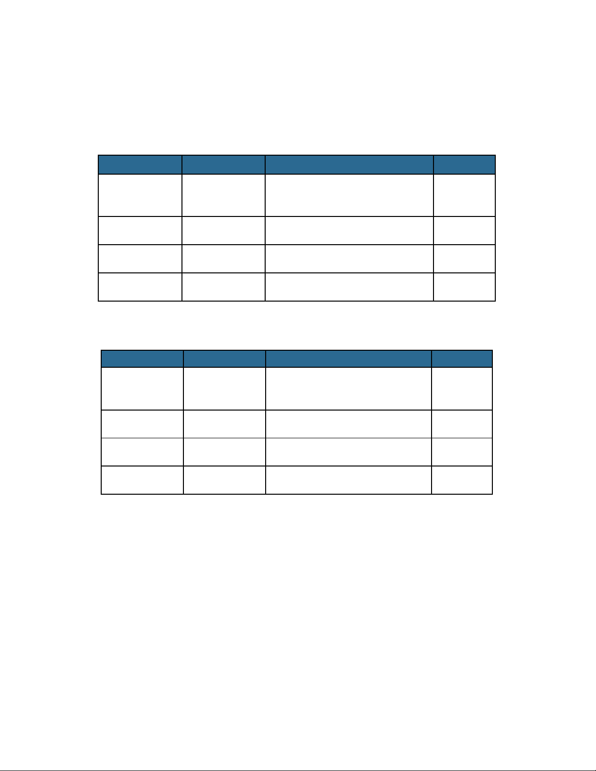
When You Open the Box
Check that the packaging and the contents are not visibly damaged.
Contact your supplier immediately if any of the parts listed below are missing or damaged
Camera Package Contents
1 21610026 or
2 31610038 Flush Mount Fixing Plate / White 1
3 31610043 Mounting hardware pkg 1
4 29010098 Installation / Operating Manual 1
Joystick Package Contents
1 21610019 Joystick Controller with mounting
2 31610046 Power cable extension 50Ft 1
3 31610050 Joystick extension 50Ft 1
V5 Dual Camera , 9Hz or 60Hz 1
21610027
Table 1 – V5 Camera Box Content
1
hardware, trim and rubber gasket
4 31610048 Video cable extension 50Ft 2
Table 2 – V5 Joystick Box Content
Document PN 29010098 V1.0 - 11 -
Page 14

ComNav V5 Installation & Operation Introduction
Safety Notes!
The following important notes must be followed carefully to run the camera and respective accessories
such as keypad controllers etc. The camera and accessories are referred to as ‘Camera system’
hereafter in this document.
The V5 Dual Imaging camera is designed to be used in conjunction with other navigational aids and
♦
should not be used as the sole or primary navigation device.
Certain Thermal Imaging Camera models cannot be exported to various territories without
♦
specific Export Licenses which must be obtained from the relevant trade and industry bodies
prior to exportation. Failure to observe strict import and export regulations is a serious
offense. Ensure the correct licenses are obtained where necessary. For further information
contact your Comnav dealer or Comnav support. Contact details can be found within this
document.
Before installing the camera, please read this manual carefully. During installation follow the
♦
instructions indicated in this manual. Please keep this manual safe for future reference. An up to
date copy is available on our website:
The installation of the Camera system including this camera and any associated accessories,
♦
should be carried out by qualified service personnel or system installers in accordance with local
regulations.
Before powering the camera please check the supply voltage and ensure the power supply is safely
♦
isolated using an appropriately rated fuse or circuit breaker. Verify that the supply power is within
acceptable range (See specifications, page 53).
Please ensure the power, video and data umbilical are stowed safely and that terminations to third
♦
party hardware or extension cables are properly shielded from moisture.
Do not operate and store the camera beyond the specified temperatures and humidity limits.
♦
To prevent electric shock and/or to not void the warranty, never remove the screws or the cover of
♦
the camera. There are no user serviceable parts within the camera housing. Refer to qualified and
approved Comnav service personnel for servicing.
Never aim the camera at the sun or other extremely bright objects
♦
Do not manually or forcefully move the camera even when it is not powered
♦
www.comnav.com
Document PN 29010098 V1.0 - 12 -
Page 15
ComNav V5 Installation & Operation Introduction
System Introduction
V5 Camera System
The V5 camera is integrated with a high quality thermal imager and a lowlight camera, both designed
for marine applications.
Unlike conventional cameras, Thermal Imaging cameras sense heat in the form of IR (Infra Red)
radiation given off by objects rather than amplifying ambient light.
The thermal imager engine inside the V5 is so sensitive that it can detect temperature differences as
low as 40mK. Cold objects such as ice emits thermal energy in the long wave infrared spectrum
sensed by the camera. Thermal Imaging cameras process radiated, rather than reflected energy.
Therefore, no source of illumination is required.
The low light module works in extremely low illuminated areas and will adjust the picture to
accommodate for such occasions. The image will turn from colour to black and white in extreme low
light condition to enhance projected image.
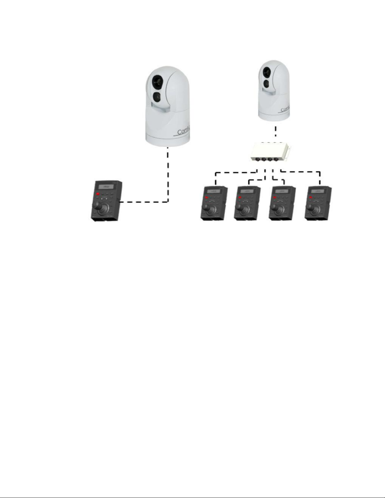
A standard V5 camera system comes with a keypad controller. Multiple cameras and multiple
controllers may be connected in one system (up to 4 each) by using a splitter switch accessory box
(see page 53 for ordering information).
Pan-Tilt-Zoom Control
Figure 1 – Various Camera Systems Setup
The pan system can rotate the camera 360° continuously. The maximum rate of pan turn is 40°/s.
The tilt system can rotate between -90° to +90° vertically. The maximum rate of tilt turn is 20°/s
Document PN 29010098 V1.0 - 13 -
Page 16

ComNav V5 Installation & Operation Introduction
Video Signal
There are two (2) 75 Ohm, Coax cable for video signal outputs:
• VBS Video Signal – compound video signal combining thermal imager and low light image into one output.
This output incorporates On Screen Display (OSD) feedback as well.
• IR Video Signal – provides thermal imager video only with no OSD support
Gyro Stabilization
The integrated gyro stabilizer assists in countering the effect of the waves on the camera’s generated
image. It allows the camera to look at the same location even when the boat is swaying due to waves.
The static accuracy of the gyro is less than 0.50 and its dynamic accuracy is less than 20.
Gyro function can be enabled or disabled through the menu using the Joystick/Keypad box.
Note: Manual Tilt control is disabled while
Gyro stabilization is engaged
Compass Integration
The camera system accepts NMEA0183 and NMEA2000 format compass data input. Data is overlaid
on the screen, to show the vessel’s heading over the display. Users can select the protocol type
through the menu selectable option (see further details in the Joystick section, page 27 ).
Please see Appendix 3 for NMEA2000 network setup and connection examples.
Note: Note the camera is a pure listener in the
NMEA 2000 network. It does not claim an
NMEA 2000 network address, and does not
send out any messages.
Joystick/Keypad Controller
The Joystick/Keypad acts as the control unit of the V5 camera system. It allows full access and control
of all the camera’s features and menu setup.
The controller is connected to the camera unit through a single Ethernet type cable. This cable also
provides the power to the controller.
Document PN 29010098 V1.0 - 14 -
Page 17
ComNav V5 Installation & Operation Introduction
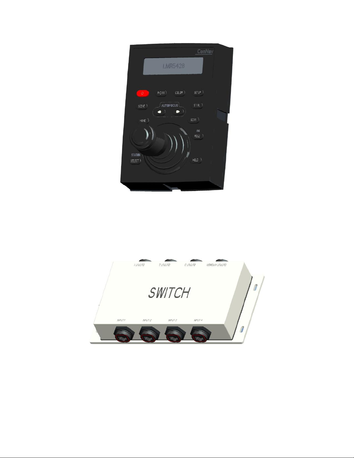
Figure 2 - Joystick/Keypad Controller
Switch Splitter Box – Optional
(For Multi controller / Multi Camera Setup)
For installations requiring multiple controllers, multiple cameras or both, a splitter box is required. This
box is connected between the controller and the camera via an Ethernet type cable, active controller
selection is done by pressing station select button on the controller.
Figure 3 - Splitter Switch Box
Document PN 29010098 V1.0 - 15 -
Page 18

ComNav V5 Installation & Operation Introduction
Document PN 29010098 V1.0 - 16 -
Page 19

ComNav V5 Installation & Operation Introduction
Document PN 29010098 V1.0 - 17 -
Page 20

ComNav V5 Installation & Operation
Installation
Installation
InstallationInstallation
Document PN 29010098 V1.0 - 18 -
Page 21

ComNav V5 Installation & Operation
Document PN 29010098 V1.0 - 19 -
Page 22
ComNav V5 Installation & Operation
Installation
Please refer to the Warranty Information section of this manual before proceeding with
installation of the V5 Camera.
Tools Required
General-purpose tools such as a portable drill, pliers, wire cutters, screwdrivers, wire, mounting
bolts and wrenches may be required, as well as an accurate voltmeter or multi-meter.
Extreme caution is advised when using tools powered by Mains
supply circuit (AC), regardless of whether those circuits are rated for
“indoor”, “outdoor”, “marine” or “industrial” use. Water, especially
sea water, is an excellent conductor of electricity. If AC tools are
used, they must be plugged into a circuit that is adequately
protected against Ground Faults and other safety hazards, and in
accordance with local and national electric codes. Failure to comply
may result is severe injury or death.
Hazard warning
Note: Battery powered tools are STRONGLY recommended
Power Supply
For a reliable operation of your V5 Camera System, your vessel’s power supply system must
have an adequate breaker circuit, or fused DC (direct current) power supply at a voltage of
12VDC-24VDC. A power on/off switch is recommended.
Ensure that adequate wire size is used to handle the expected maximum currents.
Note: It is strongly recommended that the camera’s power
wiring be run directly from the power supply – especially for
12 Volt systems.
Environmental Considerations
Ensure that the Camera system Operating & Storage Temperature is within the acceptable range
(see Specifications, Mechanical, page 51-52).
The camera components are waterproof – but they are not
Joystick/Keypad Unit
Note: Please take care when choosing the location of mounting
the Joystick controller. Refer to the last page of the manual for a
Joystick Mounting Template. You may tear this page out to use
for marking the mounting position and drill holes for the camera
joystick controller.
Note: Check the dimension of any printed template. Make sure
it is printed in the proper scale prior to drilling any holes.
submersible.
Document PN 29010098 V1.0 - 20 -
Page 23
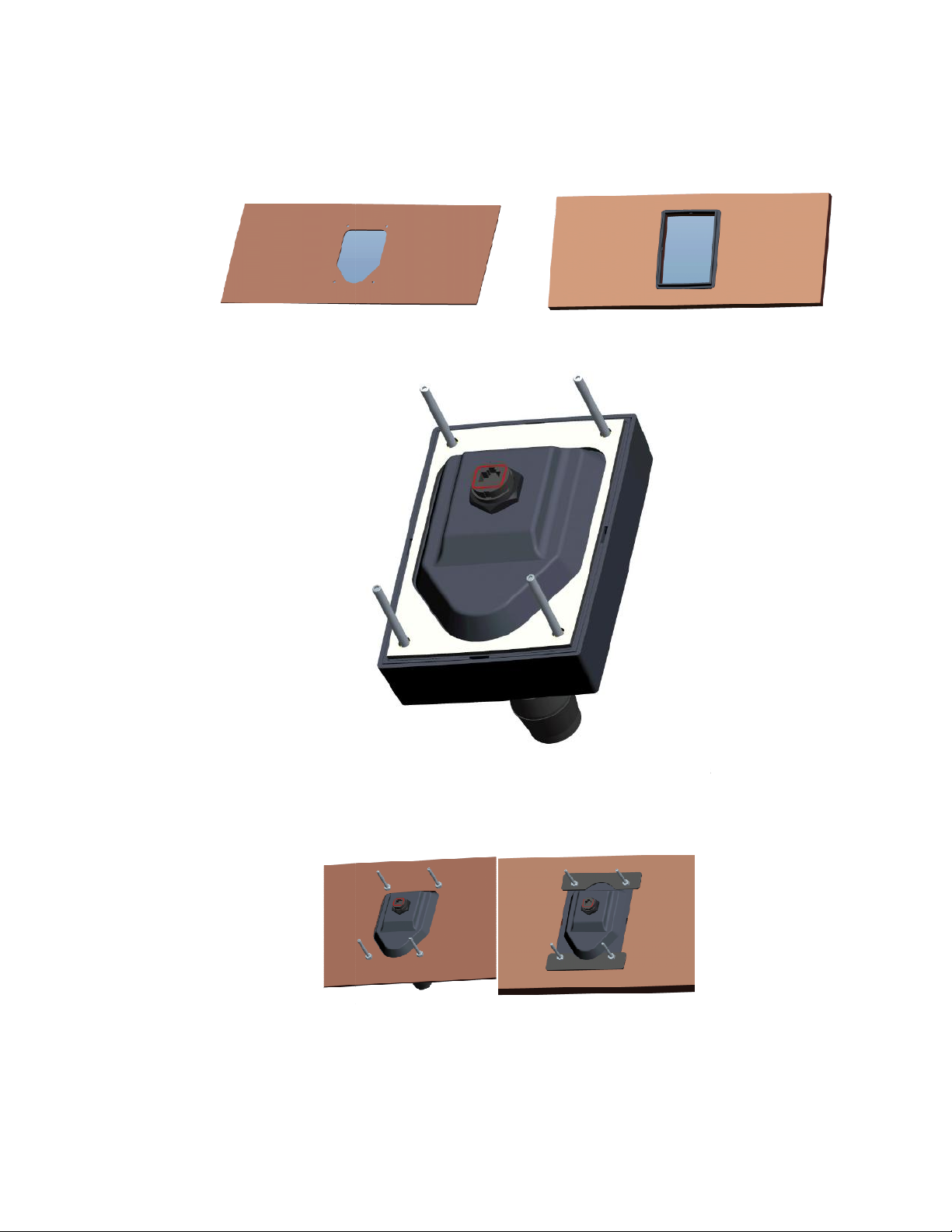
ComNav V5 Installation & Operation
the template is
pe cut out based on desired appearance. For low surface mount appearance
posts
ake sure that the rubber gasket is properly placed betwe
Position the Joystick unit in the correct orientation and place the unit into the opening
Secure Joystick controller unit to the surface using the
for low surface mount installation as depicted in option B.
Connect the Cat5 STP cable to the socket at the bottom of the joystick unit; secure the cable by
turning the cable water proof cap, clockwise;
Option A
Secure posts with
en the mounted surface and the
washers and nuts
1. Make sure that
2. Ensure proper sha
use option B;
Option A
3. Install the 4 threaded
compound;
cut out in a proper mounting position;
Option B
into the base of the Joystick.
a thread locking
4. M
joystick unit;
5.
6.
retaining bracket
7.
Document PN 29010098 V1.0
Option B
four (4)
- 21 -
;
provided; use
Page 24

ComNav V5 Installation & Operation
Camera Unit
to a power source. It is advisable to connect the power via a
breaker or by the use of a fuse. Failure to comply may result in
equipment damage.
1. Use the Surface Mount Fixing Plate as a template to mark camera position and drill mounting
holes;
2. Route prewired umbilical cable through mounting plate hole and attach the camera to the
mounting plate;
3. Secure the camera to the mounting plate using the Six (6) screws provided, secured with a
thread locking compound;
4. Position the Camera in its mounting locations and secure it using the Six (6) screws provided;
5. Connect extension cables to the camera’s embedded cables if required. For a list of available
extension and ordering information, please check the Ordering Information section, page 55;
6. Connect Video cable (BNC Connector) to the input of a video display. An adaptor might be
necessary to make such connection; video is in composite signal format.
7. Connect the Cat5 STP cable of the Joystick Unit to the Cat5 STP cable of the Camera;
8. Connect the camera power cable Red wire to positive +12 to 24 and black to negative terminal
– (GND). Make sure to enclose the connection within the water proof gland provided.
Warning: Observe polarity when connecting the power cable
Note: before drilling any holes, take care to ensure there
are no cables, conduits, pipes etc. behind the surface to be
drilled.
Note: be sure to site your camera so that it covers all
desired areas and does not obstruct any doorways or
become a hazard in walkways etc.
Note: allow sufficient space behind the surface to be drilled
for routing the umbilical cable and its connector.
Note: check the dimension of any printed template. Make sure it is
printed in the proper scale prior to drilling any holes.
Note: Make sure all electrical connections are made within the
provided gland for each connection.
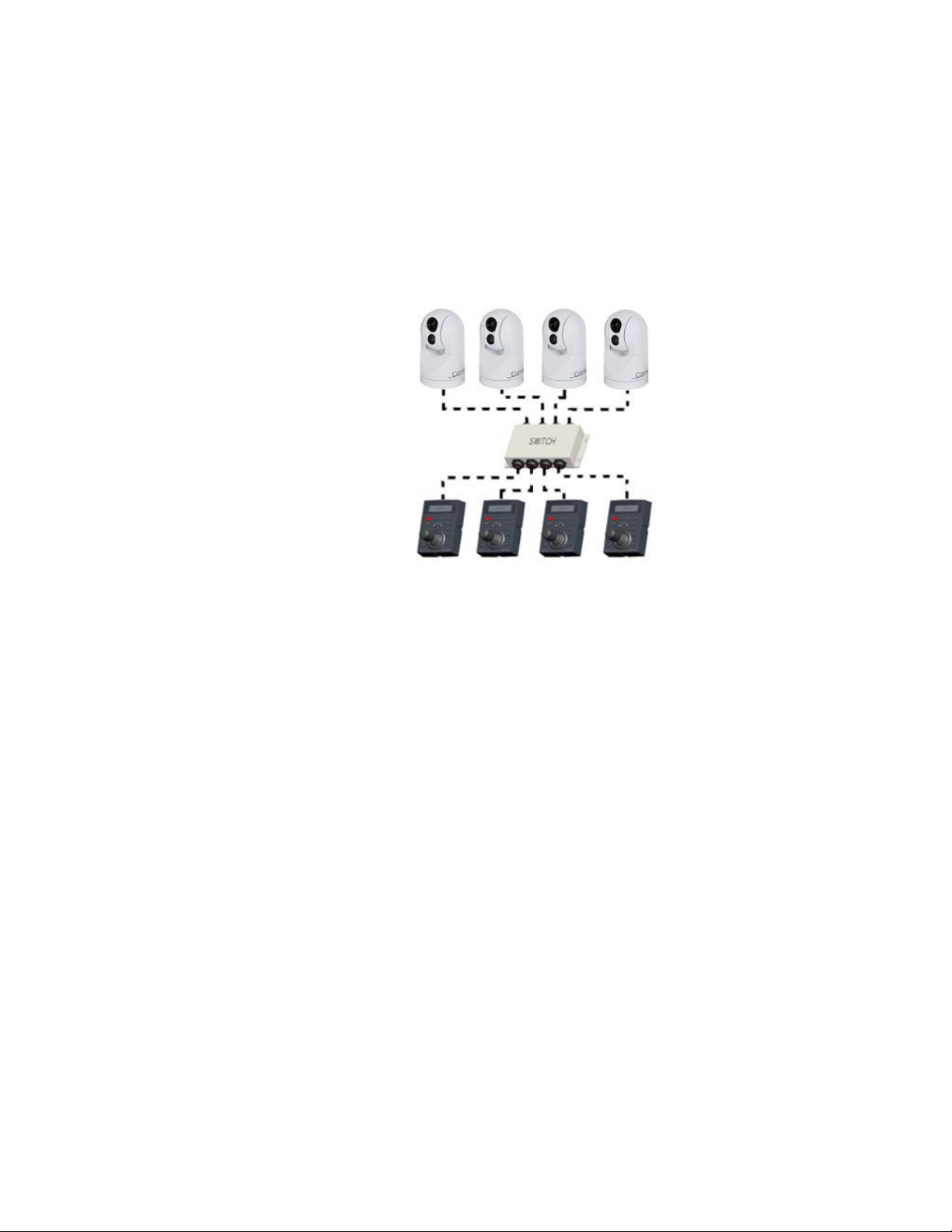
Splitter Switch for Multiple Camera system
Splitter Switch allows for multiple camera systems setup. It enables connecting multiple cameras
to one controller or connecting one camera to multiple controllers.
The switch supports Pelco-D protocol, using RS422 full duplex interface.
The maximum recommended distance for reliable communication is 1200m (when used with
0.5mm twist pair).
All communication interfaces are protected for short-circuit and over current and are designed to
recover automatically once source of short or over current is removed.
The splitter possesses similar functionality to a router in order to realize communication
distributaries. Thus, having the ability to connect 4 cameras and 4 controllers (allows 4 to 4
mode).
Document PN 29010098 V1.0 - 22 -
Page 25
ComNav V5 Installation & Operation
RJ45 connectors designated J1 to J4 connect to the Joystick keyboard. J5 to J8 connect to the
camera.
Installation Diagram
The switch is the only accessory approved for communication distribution. In a setup where only
one camera is connected, the switch is not necessary. In other installation setup where multiple
controllers and/or multiple cameras are connected, a switch must be used.
The switch gets its power supply through J8. Make sure that a camera is connected to J8 when
the switch is used regardless of how many cameras are connected.
Figure 4 - Multiple Cameras Installation
Document PN 29010098 V1.0 - 23 -
Page 26
ComNav V5 Installation & Operation
Comnav Box
Networking / Satellite Base Network
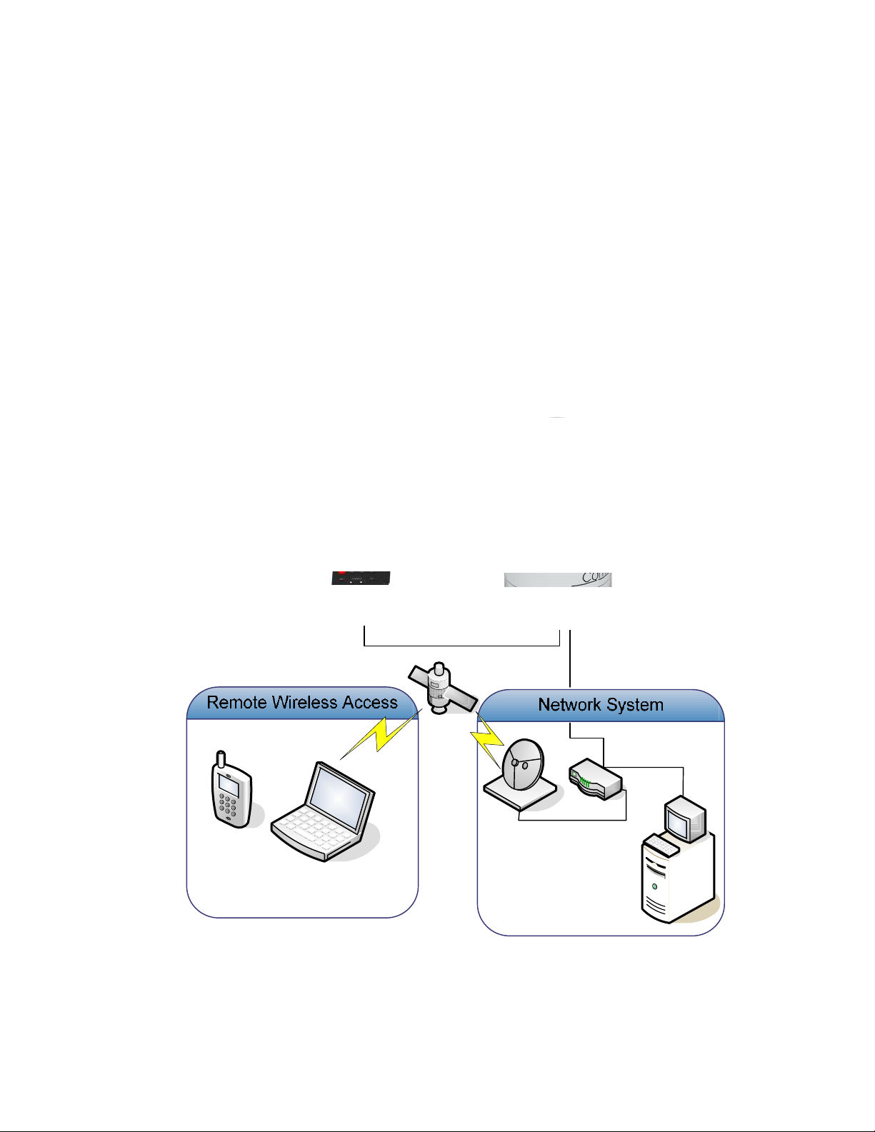
The camera system can be connected to a local network and obtain its own IP address via an
external module – Comnav Network box Interface.
Adding the network box allows the user to view the camera image on any screen connected to
the same network, and allows users on the network to control the camera, if desired, via the
computer.
The system can be connected to a remote network location via a satellite network system such
as Inmarsat. Connection via this setup allows users to view and control the camera from any
location in the world without being in the vicinity of the camera. ComNav Marine Ltd. tests
showed negligible latency.
When a computer is present at the network, a user interface loaded onto the computer allows the
control of basic camera functions via a GUI. Functions are limited, for now, to pan, tilt, and zoom
movements of the camera. Future releases may allow full feature control from any computer or
MFD connected on the same network. Call your local ComNav dealer for update information.
Figure 5 – V5 in a Network System
Document PN 29010098 V1.0 - 24 -
Page 27

ComNav V5 Installation & Operation
Operation
Operation
OperationOperation
Document PN 29010098 V1.0 - 25 -
Page 28

ComNav V5 Installation & Operation
System Start up Procedure
System Start
Note: Prior to system power up, ensure that all the cables and
connectors are properly connected and secured.
As soon as you connect the power to the camera system, the system starts an initialization
procedure. After 8 seconds, you will see the video on the screen. A COMNAV Logo will be on for
1 second, followed by a message that reads “Initializing, Please Wait”.
The camera unit starts to search for the reference points, first for the horizontal reference point,
and then for the vertical reference point.
When the reference points are found, a message “Initial Finish” will be on the screen for 1
second. After that the camera unit is on its normal operation mode.
Standby Mode
when you press and hold the power button for 2 seconds, a message “Powering Down” will be
shown on the up left of your monitor. The camera unit turns to a set position. A brief message
“System In Standby Mode” will be on the monitor for about 1 second and then the monitor goes
to blank.
Under Standby mode, the low light camera and the thermal camera are both powered down.
There will be no video output.
The system responses to “wake up” command and “display address” command in Standby
mode.
Wake up from Standby Mode
In Standby Mode, when you press and hold the power button for 2 seconds, a message
“Powering Up ... Please Wait” will be shown on the monitor screen. The camera unit will turn to
the Home position. After displaying “Power up Finish” for 1 second, the system goes back to
normal operation mode.
Document PN 29010098 V1.0 - 26 -
Page 29

ComNav V5 Installation & Operation
The joystick controller is geared so that the pan, tilt and zoom speed increases progressively
away from the central position. The closer
the further away, the faster the control.
Moving the Joystick Up/Down controls the camera head in the tilt direction, Up/Down
Moving the Joystick Left/Right controls the camera head in the pan direction, Left/Right
will automatically calculate the degree of zoom and gear the control so that the pan
Twist the joystick head clockwis
Twist the joystick head counter clockwise.
Twist the joystick head clockwise (increase zoom from X1 to X4 in 0.1 value);
Twist the joystick head counter clockwise (decrease zoom from X4 to X1 in 0.1 v
Keypad and
for 2 seconds to power down (if
When powering on, the unit goes through and initialization cycle. During this
cle the camera will move in both tilt and pan directions and display a message
“initializing….please wait”.
The camera is ready for use when the initialization message is no longer displayed.
To adjust the LCD brightness, use
illumination
toggles
Joystick’s LCD display shows which camera is being selected when the
the centre point, the slower the
proportionally as the camera zooms in and increased as the camera is
was on) or to power up the camera (if
Brightness
LowLight camera and Thermal
Operation
Camera Control
Camera Movement
control,
respectively;
respectively;
The camera
and tilt speed reduces
zooms out.
Zoom Control – Low Light
Zoom In
-
Zoom Out
-
Zoom Control - Thermal
Zoom In
-
Zoom Out
-
the joystick is to
e;
alue).
Joystick Controller
Functions
Power Button ( )
Press and hold
system was off);
cy
through four
a single short press of the button.
setting levels.
system
IR/CAM
A single button press
cameras.
pressed.
Document PN 29010098 V1.0
the video output signal between the
- 27 -
levels cycle
button is
Page 30

ComNav V5 Installation & Operation
COLOR
Toggles the thermal imager colour scheme through all selections: “CUSTOM”, “INFERNO”,
“SOFT LIGHT“, “ARCUS”, ”FULL SPECTRUM”, “MEMORIAM”, “OCEAN”.
For “CUSTOM” option, the polarity of the hot color depends on the setting of “AGC Polarity”. See
“AGC Polarity” for details.
This button has no effect when the LowLight camera is selected.
SCENE
Toggle the image setting of the LowLight camera though the 3 choices of: “Auto”, “Day”, and
“Night”. It affects image contrast and image settings. This button has no effect when the thermal
camera is selected.
Auto
– in this mode, the camera will adjust the image appearance and setting based on the
environments illumination. As light becomes dimmer, the colour will be “drained” from the picture
and become black and white.
Day – in this mode, the camera is forced into color mode regardless of the environment’s level of
illumination. This may affect the clarity and details visible in the image with poorly illuminated
areas.
Night – in this mode, the camera is forced into a black and white operation mode regardless of
the environment’s level of illumination. Although it improves image clarity in low illumination
areas, it does not provide the colourful, vivid and detailed image available in normal lighting
modes.
POS1/POS2
These buttons allow fast direct access to programming and recalling 2 of the 8 available
positions without scrolling through the menu.
Pressing and holding either POS1 or POS2 buttons down for 3 seconds programs the current
position of the camera (pan, tilt and zoom) into memory, referenced by that specific button.
A single short press on either POS1 or POS2 buttons, recalls that position from the memory and
moves the camera to the stored pan and tilt position with the stored zoom level.
SELECT
Allows users to select the Joystick and camera to be controlled when multiple controllers and/or
cameras are connected via the ComNav splitter box.
To select a specific camera to control, press and hold the button for 3 seconds to enter into
camera address selection mode. The camera address will be blinking while configuration is
enabled. press the of and to change the camera address number to the desired camera
(1,2,3 or 4). Confirm your selection by pressing the accept button.
If the Joystick you wish to control the camera with is not selected or active, its LCD screen will
display “Not Active”. To select this Joysticks press a single short press on the SELECT button.
Once selection is completed, the Joystick’s LCD will display “Active”.
AUTOFOCUS
Allows selection of auto / manual focus adjustment for near / far focus settings. This feature is
available only with the low light camera and the thermal imager equipped with a 50mm lens.
Simultaneous press of and toggles between auto/manual focus in low light camera mode.
Document PN 29010098 V1.0 - 28 -
Page 31

ComNav V5 Installation & Operation
Pressing the left side arrow button will focus far. Pressing the right side arrow button will
focus near.
STAB.
Toggle between the enable and disable of the camera’s Gyro stabilization system. Use this
option when in rough water ways or sea to keep the image centred on the area in the field of
view.
When this feature is active, the message “Stabilization on” will be overlaid in the top part of the
image on the screen.
SCAN
Activates the onboard camera scan patterns as follows:
- Single short press initiates clockwise, Pan only scan;
- A three (3) seconds press initiated Zigzag type scan (both Tilt and Pan scan simultaneously)
Note: 35mm lens, thermal imager
focus can not be controlled.
Note: any button press or any
movement of the joystick, stops the
scan
HOLD
HOME
SETUP
One press freezes the camera’s image. Any button press or joystick movement releases the
freeze. This option is only available with the lowlight camera.
This button allows fast direct access to programming and recalling the home positions without
scrolling through the menu.
Pressing and holding HOME button down for 3 seconds programs the current position of the
camera (pan, tilt and zoom) into memory, referenced by the HOME button.
A single short press on HOME button, recalls that position from the memory and moves the
camera to the stored pan and tilt position with the stored zoom.
Note: it is recommended to set this
position in the direction of the vessel’s
centre line of the bow. This will allow for
a proper reading of the camera
direction in reference to the vessel’s
heading.
A single short press initiated on screen menu selections. Menu selections allow the user to
customize and configure certain features of the camera and manipulate certain image processing
properties. See page 26 for menu selection details.
THREE AXIS JOYSTICK
Controls the camera’s movement
Document PN 29010098 V1.0 - 29 -
Page 32

ComNav V5 Installation & Operation
Moving the joystick up/down controls tilt motion
Moving the joystick left/right controls pan motion
CW and CCW to zoom in and out
The button located on the Joystick itself is active only i
the button for three (3) seconds enables the user to control the camera’s Iris
moving the joystick left/right changes Iris setting. Press on the button again to exit Iris mode.
describes the
. These symbols can be disabled
ICON
he Yellow triangles type shape
It is important to set the zero
accurate relative reading. The resolution of the camera direction is 2
When connected to an external compass (NME
displayed to the right of this icon in the format of X
Indicates LowLight camera mode
Indicates Thermal imager camera m
GYRO STABILIZATION ICON
Gyro stabilization system is active.
Indicates Gyro stabilization system is not active
Indicate video feed signal is held “frozen” on the screen and not being refreshed.
LOWLIGHT ONLY
Indicates auto mode for low light scene selection.
LOWLIGHT ONLY
time mode for low light scene selection.
LOWLIGHT ONLY
mode for low light scene selection
t camera mode
the On
camera’s
ction in reference to the
n of the camera to vessel’s bow
A0183 or NMEA2000), a compass heading is
1.
2.
3. Twist joystick
4.
On Screen Display Symbols
This section
(OSD)
POSITION INDICATION
T
vessel’s bow.
Default setting in ON.
CAMERA ICON
.
.
respectively.
n LowLigh
meaning of the symbols which appear on
through customizing in the
Indicates the camera’s field of view dire
(home) positio
0
. X range is 00 to 3590.
– pressing
. In this mode,
-Screen-Display
menu.
0
centre line, to ensure
.
THERMAL CAMERA ICON
Indicates
IMAGE FREEZE ICON
AUTO MODE ICON –
DAY TIME ICON –
Indicates day
NIGHT TIME ICON –
active.
ode active.
.
Indicates night time
Document PN 29010098 V1.0
- 30 -
.
Page 33

ComNav V5 Installation & Operation
Note: Day time mode outputs colour image. Night time
mode outputs black and white image for improved vision
in a dark environment. Auto mode outputs colour in day
time mode and switches to black and white when external
light level becomes low. Default setting is Auto.
ZOOM DISPLAY
LowLight camera – displays zoom levels from X1 to X36 as a default setting. If digital zoom is
enabled, zoom level display is in the range of X1 to X432
Thermal Imager – displays zoom levels from X1 to X4 in 0.1 step increments.
MENU NAVIGATION AND SETUP
Menu navigation
Users can navigate the built-in OSD menu on the video screen by using the joystick controller.
Table 3 lists what keys on the joystick controller are to be used for menu navigations.
Menu Operation User Action
Enter menu Press “SETUP”
Enter the next menu level (Submenu) Press “Accept” (POS1) key
Back to previous menu Press “Esc” (POS2) Key
Confirm selection Press “Accept” (POS1) key
Cancel selection Press “Esc” (POS2) Key
Cursor Control Move Joystick up/down and left/right
Change parameter value Once the cursor is in the required position,
Screen indications:
Red background indicates the cursor’s position
“< >” indicates that the specific menu line has a selectable submenu.
Table 3 - OSD Menu Operation Summary
PASSWORD SELECTION
If no password was set, pressing “SETUP” enter the main menu directly.
If password was set, pressing “SETUP” key prompts the user to input the password “Input
Password [xxxxxx] ”, with the first “x” flickering. Move the joystick up/down to change the value
and right/left to move on right and left. Press “Accept” to enter the main menu. If the wrong
password was entered, “Input Again [xxxxxx] shows until the correct password is entered. There
is no limit on the number of password entry attempts. Upon successful password entry, the main
menu displays on the screen as depicted below.
press “Accept”, the parameter value blinks,
move the joystick up or down to change the
value. Press “Accept” to confirm selection or
“Esc” to cancel.
Document PN 29010098 V1.0 - 31 -
Page 34
ComNav V5 Installation & Operation
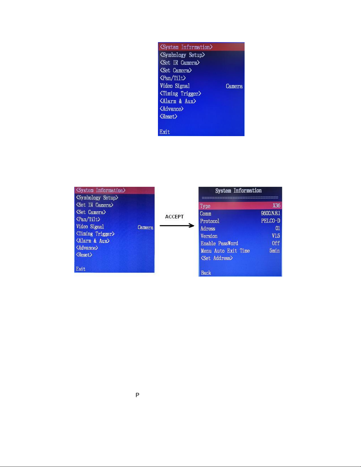
<SYSTEM INFORMATION> SUBMENU
Figure 6 - Main Menu
Figure 7 – System Information menu
Pressing ACCEPT key when <System Information> is highlighted enters System Information
submenu. Each item in the submenu is explained below
Type
Camera zoom setting, x36 means 36 times zoom. x36 is the Default setting this value cannot be
changed in this menu but overall zoom range can be changed. See page 35.
Comm
Communication port setting: 9600 - Baud rate; N - no parity; 8 - data bits; 1 - 1 stop bit. This is
the Default setting and cannot be changed by the user.
Protocol
Communication type: Pelco D. Default setting and cannot be changed by the user.
Address
Display address assigned to this camera.
Document PN 29010098 V1.0 - 32 -
Page 35
ComNav V5 Installation & Operation
Version
Camera Firmware version.
Enable Password
Password Enable status:
On - password protection enabled.
Off - password protection disabled.
Default setting: OFF
Menu Auto Exit Time
Length of time for the Menu to be displayed after the last change was made, without selecting to
exit the menu. Settings available: 2,3,4,5,6,7,8,9,10 minutes. Default setting: 5 Min
When there is no menu operation for the set time, the OSD menu on the screen will disappear.
<Set Address>
<Set Address> initiates Set Address submenu.
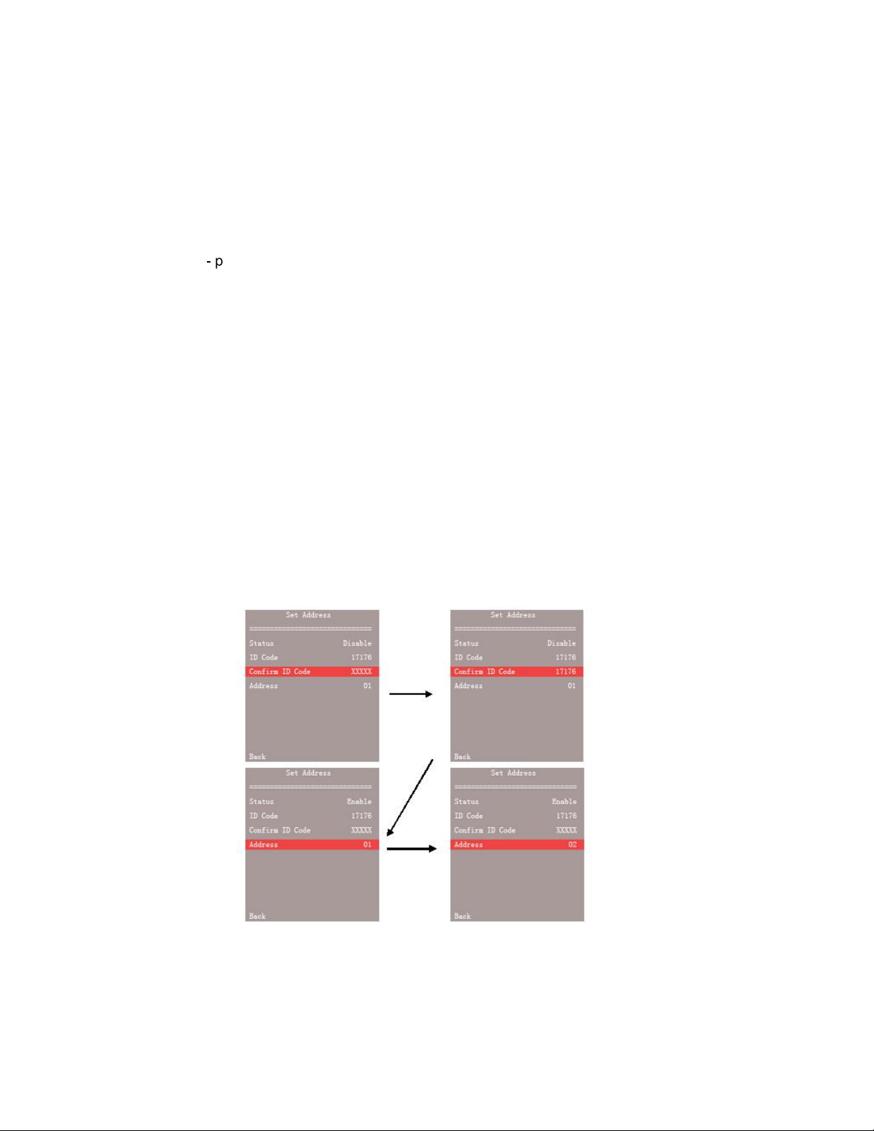
The camera system has an out-of-factory default address 01. When multiple cameras are
connected (maximum of 4); each camera installed on the same system must have a different
address. To change the default address, enter the address setting menu; enter the ID number in
“confirm code” field. The ID number is the five digits in “ID code” field. Address can be changed
only when the correct ID number is entered. See below for an example of changing the address
to 02:
Figure 8 - Change Camera System Address
Back
Go back to previous menu level
Document PN 29010098 V1.0 - 33 -
Page 36
ComNav V5 Installation & Operation
<SYMBOLOGY SETUP> SUBMENU
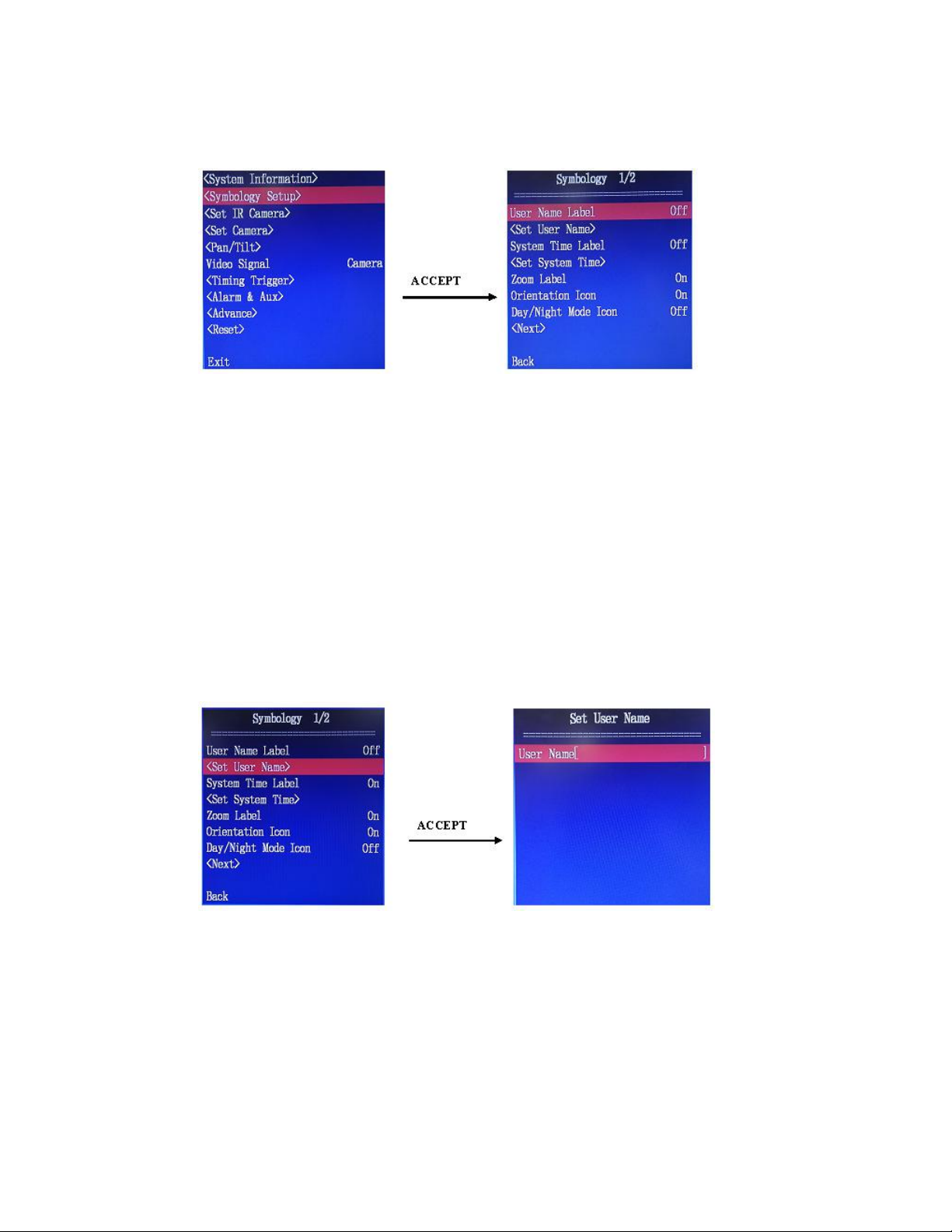
Figure 9 - Entering Symbology Setup
Pressing ACCEPT key when <Symbology Setup> is highlighted enters Symbology Setup
submenu. Each item in the submenu is explained below
User Name Label
Enable or disable user name display on the screen:
Off – user name will not be displayed on the screen (Default setting)
On – user name will be displayed
<Set User Name>
This item has a submenu to allow the user customizes the user name. A user name can have up
to 12 characters.
When you enter the <Set User Name>, you are prompted with User Name[ ] on the
screen. Out of the factory the User Name is empty.
Figure 10 - Out of factory empty user name
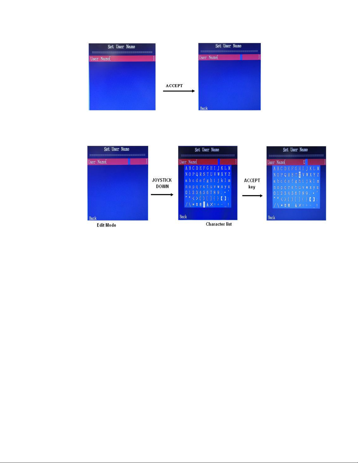
Following steps below to enter a text string.
1. Press ACCEPT on the controller to enter edit mode. A blue cursor is seen in the bracket as
below.
Document PN 29010098 V1.0 - 34 -
Page 37
ComNav V5 Installation & Operation
Figure 11 - Enter User Name Edit mode
2. Push the joystick left or right to move the cursor to cover a character if you want to modify an
existing name.
3. Push the joystick down to bring up a list of characters. The highlighted character will blink.
Figure 12 – Enter a character
4. Use the joystick to move the blink cursor to the character you want.
5. Press ACCEPT to select the highlighted character. The selected character will be shown in
the rectangular bracket.
6. Repeat Step 4 and 5 to select all characters in your name. Up to 12 characters can be
accepted for a user name.
7. Press ESC to exit the character list. If more than 12 characters have been selected, the
character list will be automatically closed.
8. Press ACCEPT to save the name and exit the submenu
The Space character is between character @ and & in the list. When the Space character is
highlight, the cursor will not blink.
The Space character can be used to delete a character in an existing name, or even to delete
the existing name. This is done by selecting the Space to override all existing characters.
System Time Label
Enable or disable date and time display on the screen. Default setting is Off.
Document PN 29010098 V1.0 - 35 -
Page 38
ComNav V5 Installation & Operation
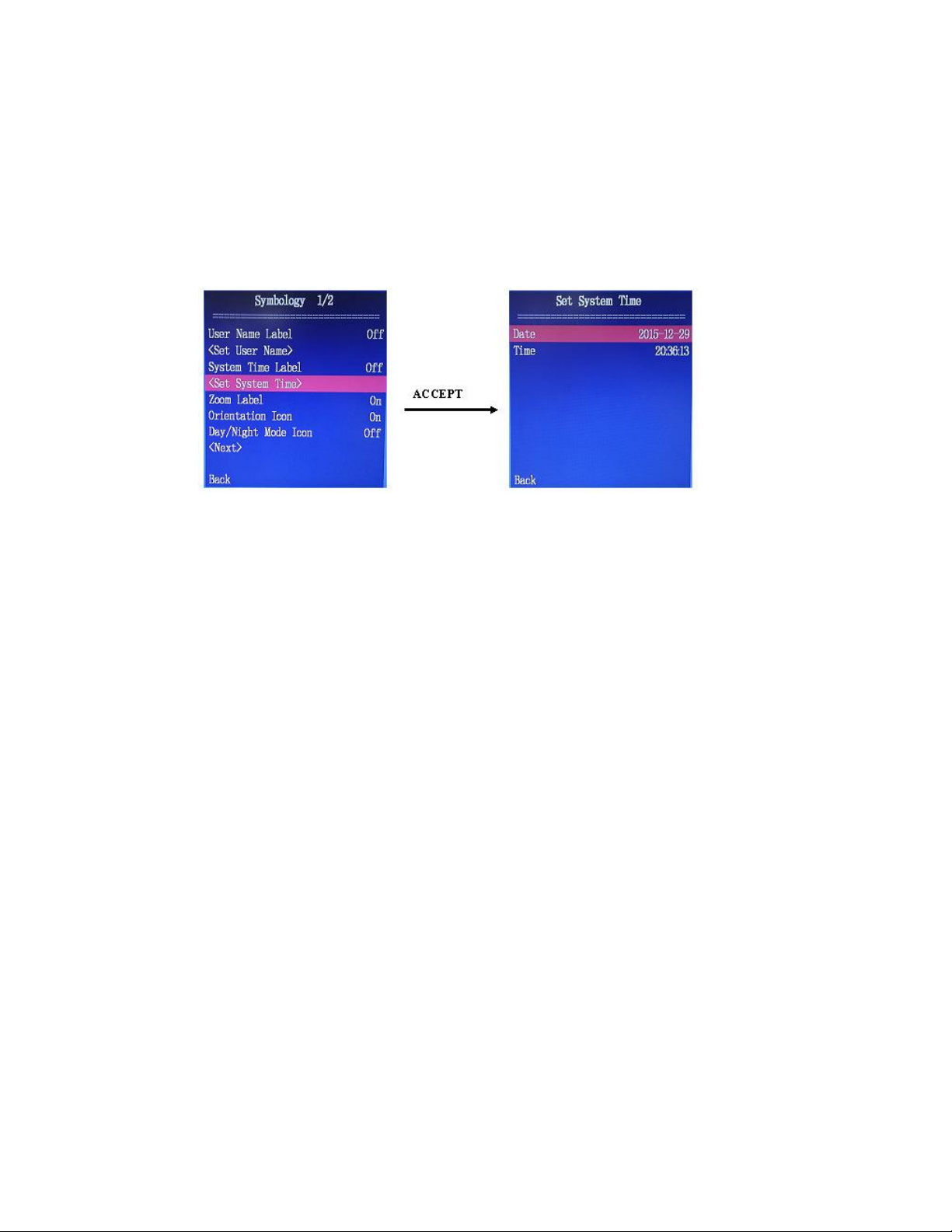
<Set System Time>
This is a submenu to allow the user to set the local time and date for the camera system. Use
ACCEPT key to enter the submenu.
The format of Date is yyyy-mm-dd, and the format for Time is hh:mm:ss.
To modify a year or a month or a day in Date, press ACCEPT to enter date editing. Push the
joystick left and right to a digit to be modified, and push the joystick up and down to increase or
decrease the value. When the date is correct, press ACCEPT to save it. The new date will take
immediate effect.
If you want to cancel the editing, press ESC key.
The procedure to modify the Time is similar.
Note: The camera has a battery that can last approximately 2 years out of the factory. You only
need to set the local time once as long as the battery works. If the battery has depleted, the Date
will return to 2015-12-12 and Time to 00:00:00 every time the system powers on.
Zoom Label
Enable/Disable Zoom level display on the screen. Default setting in On.
Orientation Icon
Enable/Disable Orientation Icon (Vessel image with camera FOV indication) display on the
screen. Default setting in On.
Day/Night Mode Icon
Enable/Disable Day/Night/Auto symbol display on the screen. Option active in LowLight camera
only.
Default setting: On.
Document PN 29010098 V1.0 - 36 -
Page 39
ComNav V5 Installation & Operation
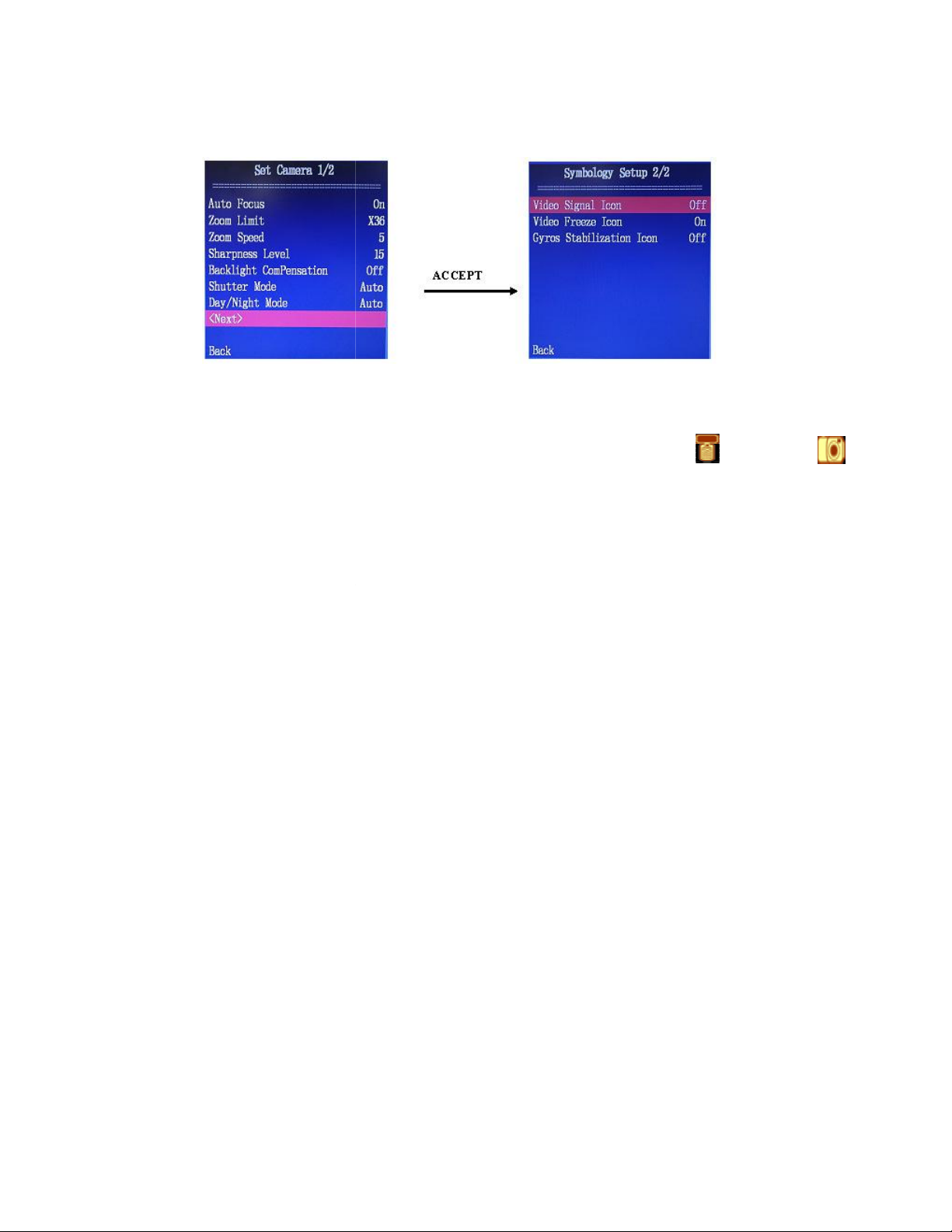
Continue to the second page of the
Second page of Symbology Setup
the display of the video signal source
the display of the freeze icon on the screen
Users can freeze the video signal input by pressing the
, the icon will be displayed when us
the video signal starts to refresh again.
This menu item only affect the lowlight camera.
Gyro Stabilization Icon
the display of the Gyro St
If Enabled, when the Gyro control is on, an icon will be displayed.
When
video signal. The icon disappear when
<Next>
Figure 13 -
Video Signal Icon
“Symbology Setup” Submenu.
Enable/Disable
camera.
Default setting: On.
Freeze Signal Icon
Enable/Disable
is On
Default setting: On.
Enable/disable
Default setting: On.
symbol, Thermal (
) or low light ( )
.
Hold butten.
Freeze Signal Icon
ers freeze the
abilization icon on the screen.
Document PN 29010098 V1.0
- 37 -
Page 40
ComNav V5 Installation & Operation
<SET IR CAMERA> SUBMENU
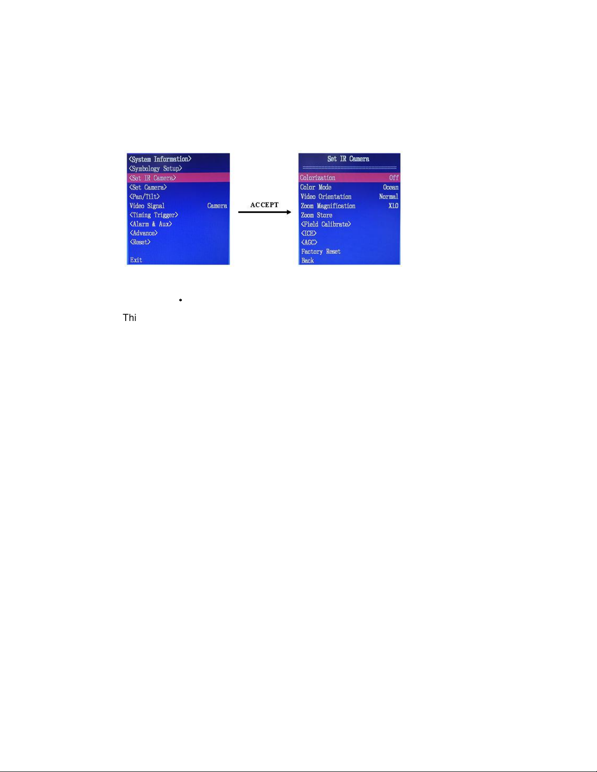
This menu is Active only when the thermal video signal is selected. If the system is in LowLight
video mode, the submenu will have the word "Disabled" displayed next to it and entry to the
submenu is not possible.
The IR Camera submenu is designed for various thermal cameras. Some of functions may not
applicable to the thermal camera in your system model.
Figure 14 - Enter IR CAMERA setup menu
Colorization
This item does not apply to V5.
Color Mode
Select a Pseudo-color scheme.
There are 7 different colour schemes: “CUSTOM”, “INFERNO”, “SOFT LIGHT“, “ARCUS”, ”FULL
SPECTRUM”, “MEMORIAM”, “OCEAN”.
In “CUSTOM” mode, the hot color can be set to white or black through the AGC submenu.
Video Orientation
Select the display orientation of the thermal image. Available options are “Normal”, “V-Invert”, “HInvert”, and “HV-Invert”.
Zoom Magnification
Select the thermal image’s zooming factor. The factor range is from 1.0 to 4.0 in the step of 0.25.
Zoom Store
Use this item to save Zoom Magnification value.
****
Document PN 29010098 V1.0 - 38 -
Page 41
ComNav V5 Installation & Operation
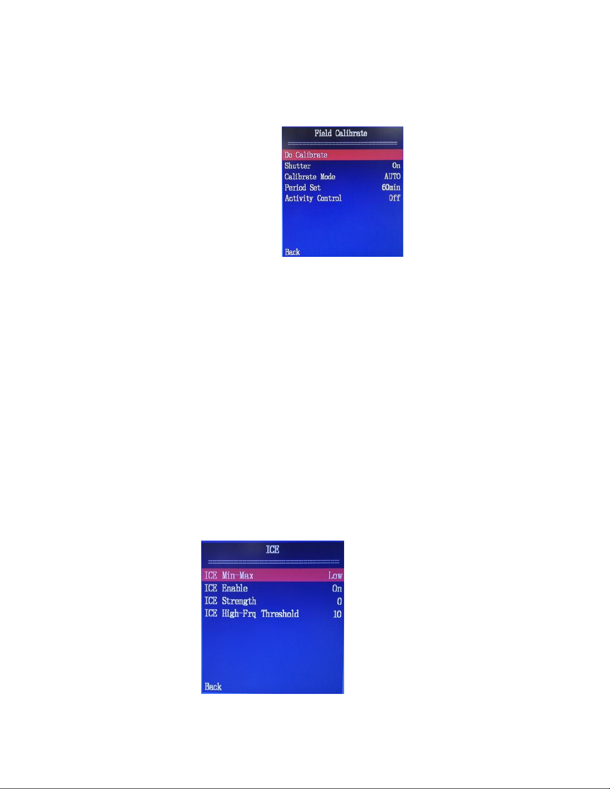
<Field Calibration>
This menu is used to perform thermal image calibration or non-uniformity correction (NUC)
through Field Calibrate menu.
Do Calibration
Carry out 1-point NUC once.
Shutter
Turn on or off the camera shutter.
Calibrate Mode
Set Calibration mode to AUTO or Manual
Period Set
Time interval for Auto Calibration in minute. Valid values are from 1 to 100 minutes.
Activity Control
Turn on or off Auto Calibration.
<ICE >
Image Contrast Enhancement (ICE) independently adjusts the gain and level settings for
different “localized” areas of the image based on spatial frequency and an object’s individual
brightness and contrast.
Figure 15 - Field Calibration Submenu
Figure 16 – ICE menu
Document PN 29010098 V1.0 - 39 -
Page 42
ComNav V5 Installation & Operation
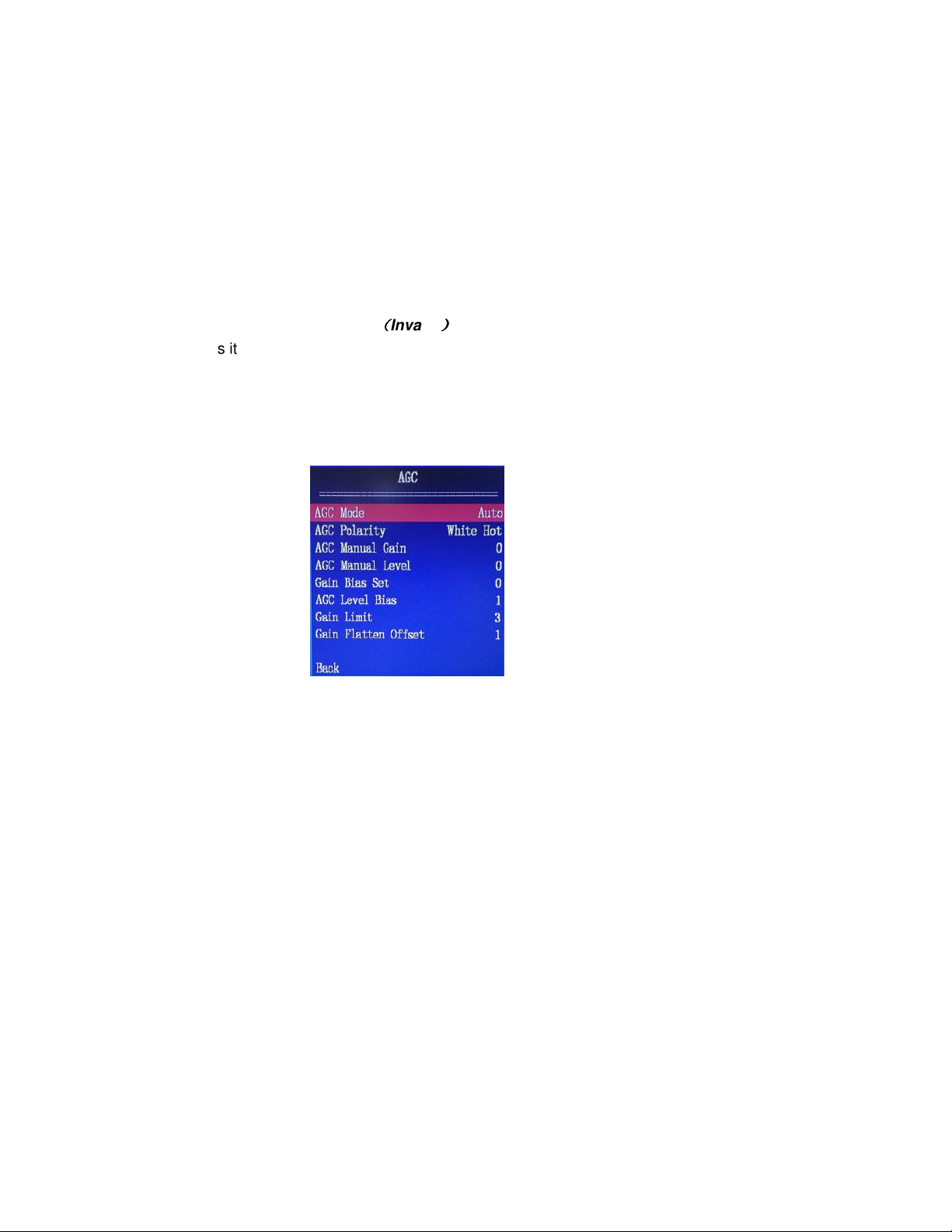
ICE Min-Max
Set ICE strength for Low or High. For V5, a better fine tune can be achieved using ICE Strength
ICE Enable
Turn on or off ICE configuration.
ICE Strength
Select ICE gain and level settings from 0 to 7. This is a fine tune of ICE Min-Max.
ICE High-Frq Threshold
This item is reserved for future expansion.
<AGC>
Automatic Gain Control (AGC) allows an operator to control image output intensity and contrast.
Adjusting the Gain Bias Set and AGC Level Bias may improve how the detected energy is
shown on a video monitor.
((((
Invalid
))))
Figure 17 - AGC Submenu
AGC Mode
Fixed at AUTO mode.
AGC Polarity
Two options available: “White Hot” and “Black Hot”.
When the polarity is set to “White Hot”, hot pixels are shown as white and cold pixels are shown
as black.
When the polarity is set to “Black Hot”, hot pixels are shown as black and cold pixels are shown
as white.
Note you can also use the push button on the top of the joystick to toggle between “White Hot”
and “Black Hot”. The polarity selected in this way will not be saved after power off.
AGC Manual Gain
This item is not used.
AGC Manul Level
This item is not used.
Gain Bias Set
Document PN 29010098 V1.0 - 40 -
Page 43
ComNav V5 Installation & Operation
Gain Bias can be adjusted from -9 to 9.
AGC Level Bias
Level bias can be adjusted from -9 to 9.
Gain Limit
This item is not used.
Gain Flatten Offset
This item is not used
Factory Reset
Return all parameters to their factory defaults.
<SET CAMERA> SUBMENU
Active only when the LowLight video signal is selected. If the system is in Thermal video mode,
the submenu will have the word "Disabled" displayed next to it and entry to the submenu is not
available.
This menu is to set configurable items for the lowlight camera.
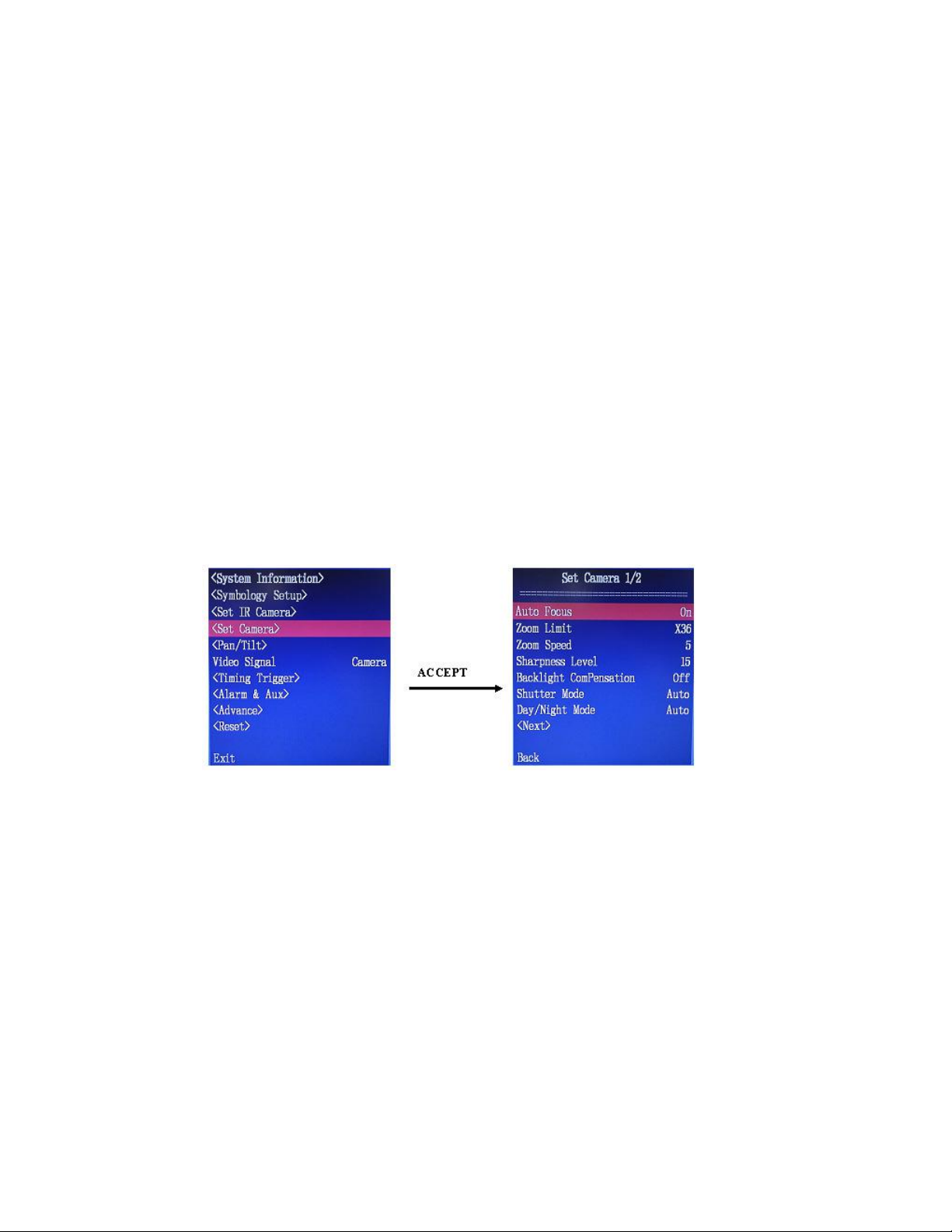
Figure 18 - Enter Set Camera submenu
Auto Focus
Enabling/disable auto focus function by selecting On or Off. Default setting: On
Zoom Limit
Allows the user to set Zoom function Limit levels to X 36 or X432. A zoom of X36 enables the
optical zoom only while a setting of X432 enables the digital zoom as well for levels beyond X36
zoom.
Default setting: x36
Zoom Speed
Set zoom speed. Select values between 1-7 where 7 is the highest zoom speed allowed. Default
setting: 5
Sharpness Level
Document PN 29010098 V1.0 - 41 -
Page 44
ComNav V5 Installation & Operation
Set sharpness level. Values between 0-15 and Auto are available.
Default setting: Auto
Backlight Compensation
Enable/disable Backlight compensation. Default setting: OFF
Shutter Mode
Select Shutter Mode as Auto or fixed exposure time between 1/1 to 1/10000. Default setting:
Auto
Day/Night Mode
Select Day or Night mode. Options are Auto, Day, and Night
• Day – forces camera to be in color mode regardless of illumination level. This may
reduce visibility of objects in dark areas due to the reduced contrast available in color
mode.
• Night – forces camera into a black and white mode regardless of illumination levels. This
condition improves the camera contrast performance and is a better option for low
illumination or dark areas.
• Auto – this option lets the camera switch automatically between the color option and the
black and white option based on the level of illumination in the area measured by the
camera’s illumination sensor.
Default setting: Auto
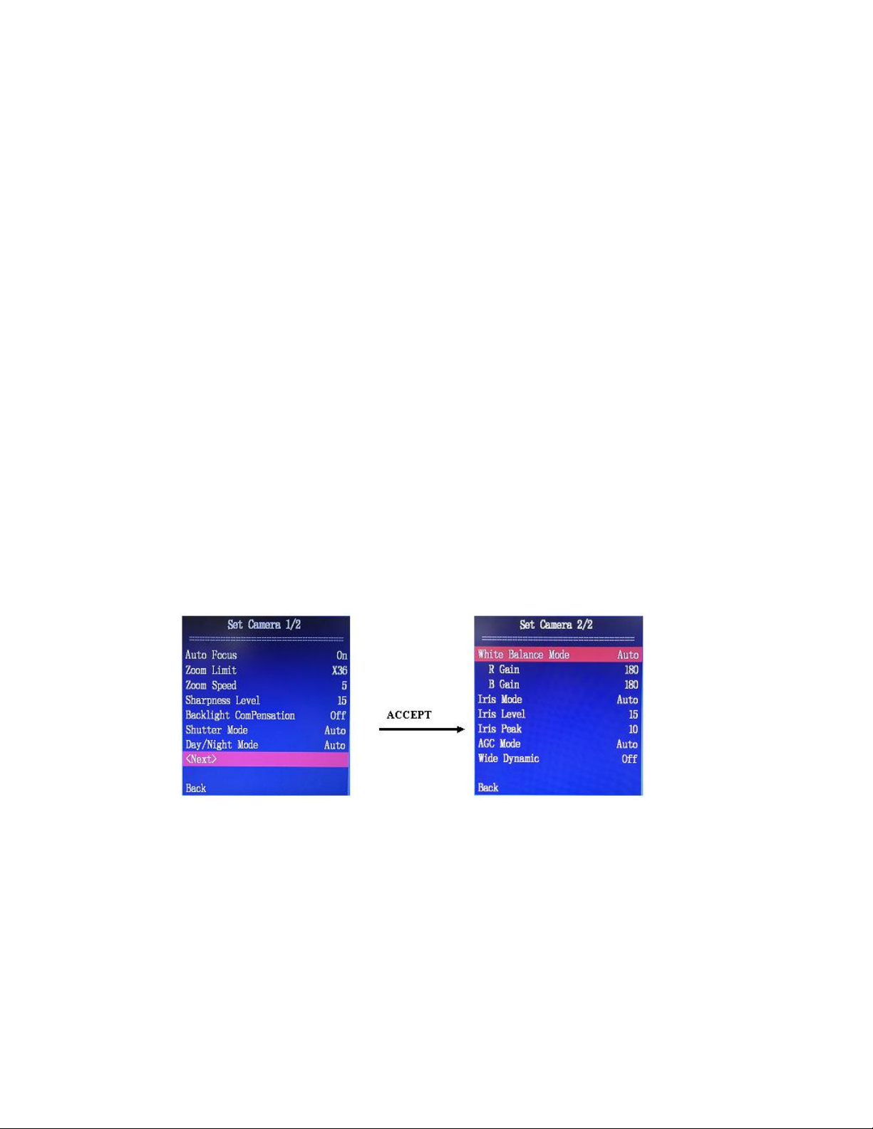
<Next>
Continue to the second page of the “Set Camera” Submenu
Figure 19 - Enter the second page of Set Camera submenu
White Balance Mode
Select white balance mode. Options are Auto, Indoor, Outdoor, OnePush, ATW, and Manual.
• Auto – This mode computes the white balance value output using color information from
the entire screen. The value uses the color temperature radiating from a black subject
based on a range of values from 3000K to 7500K. This mode it factory set.
• ATW – Auto Tracing White balance (2000K to 10000K)
• Indoor – 3200K base mode.
• Outdoor – 5800K base mode.
Document PN 29010098 V1.0 - 42 -
Page 45

ComNav V5 Installation & Operation
• One Push – this sis a fixed white balance mode that may be automatically adjusted only
by the user’s request, assuming that a white subject, in correct lighting conditions,
occupying more than 50% of the image in front of the camera. This setting is lost once
the camera is turned off.
• Manual – sets manual control to enable R and B Gain value change.
Default setting: Auto
R Gain
Set Red colour Gain. Gain can be set only when white balance mode is set to Manual. Available
range: 0-255. Default setting: 180
B Gain
Blue colour Gain. Gain can be set only when white balance mode is set to Manual. Available
range: 0-255. Default setting: 180
Iris Mode
Set Iris Mode to Auto or Manual. Default setting: Auto
Iris Level
Set iris level. Iris level can be set only when Iris Mode is set to manual. Available range: 0-17.
Default setting: 15
Iris Peak
Setting iris Peak level. Available range: 1-10. Default setting: 10
AGC Mode
Set AGC (Automatic Gain Control) to Auto or a fixed level. This offsets the internal brightness
levels of the camera. The higher the number the brighter the image (high number may cause it to
“fade” color). Available level range:-3db to 28db in an increment step of 2. Default setting: Auto
Wide Dynamic
Enable wide dynamic mode. Set to ON or OFF. Default setting: OFF
This function is very effective when shooting against the sun or a very bright subject. The camera
can combine shot of high brightness and normal shutter speed with shot of high shutter speed.
The shutter automatically changes shutter speed up to X128 times depending on the level of the
high intensity images to obtain the best combined image.
Back
Go back to previous menu level
Note: when this function is ON, parts of the image may appear
solarised. This is normal in this mode and does not indicate a
camera malfunction.
Document PN 29010098 V1.0 - 43 -
Page 46
ComNav V5 Installation & Operation
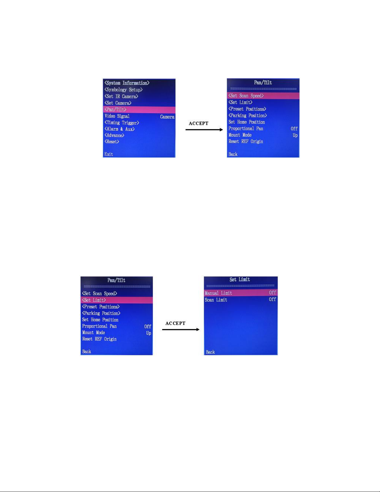
<PAN/TILT> SUBMENU
This menu configures parameters for the pan/tilt system.
Figure 20 - Enter Pan/Tilt Submenu
<Set Scan Speed>
Users can adjust the camera’s tilt and pan motion scan speed parameter. The speed is set in
degrees per minute rate and will determine how fast the camera will move in the tilt and pan axis.
- Pan speed can be set between 0-40 O/S, in 1O increments. Default setting: 10O/S.
- Tilt speed can be set between 0-20 O/S, in 1O increments. Default setting: 05O/S.
<Set Limit>
In this menu, the user can access and set the camera’s motion limitation or border. These limits
are areas where the camera is prevented from reaching.
Figure 21 - Set Pan/Tilt limits
Manual Limit
This option allows the user to turn on/off the Limit of pan/tilt position when the user controls the
pan/tilt motion through the joystick manually. When this limit is set to be On, the camera cannot
move beyond the limited position.
Two options available: ON/OFF. Default setting: OFF
Scan Limit
Document PN 29010098 V1.0 - 44 -
Page 47
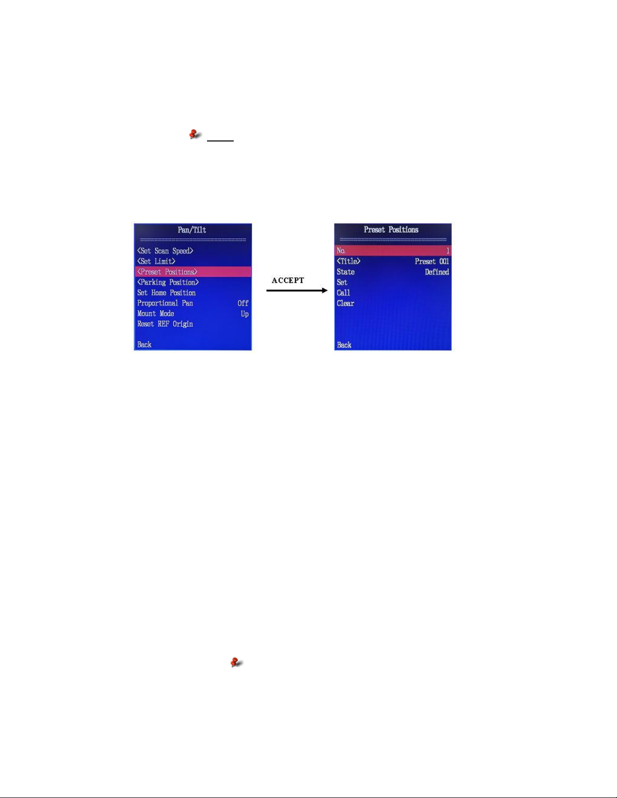
ComNav V5 Installation & Operation
This option allows the user to turn on/off Limit of pan/tilt position during scan operation. The
camera cannot move beyond the limited position when it carries out a pre-set scanning patterns.
Two options: ON/OFF Default setting: OFF
<PRESET POSITIONS>
This menu allows the user to set up to 8 positions to be set, recalled, or cleared. The user can
also setup 4 positions as the limits for pan left/right and tilt up/down movement.
Note: See preset position section for limit setting
instructions.
Figure 22 - Setup pre-defined positions
No.
Define Preset Number to be edited. Preset numbers 1-8 are available.
There are four special presets: 90,91,92,93.
90: Up limit, 91: Down limit, 92: Left limit, 93: Right limit. These limit presets can be set or
cleared but not run. Preset number is always at 001 upon entering this submenu.
<Title>
A maximum of 12 characters can be used to give a special name for each preset. Refer to the
user name entry section (page 29) for character entry details. The title of a special preset can not
change. The default title setting is “Preset XXX”, such as “Preset 001”. The title of a special
preset represents its function, such as preset 90 “UP Limit”.
State
Status feedback with 3 options: Defined, Undefined or “Specific” for a special preset.
Set
Defining a preset - when selected, “setting” blinks in this position, user can then move the
camera to the desired position and press “accept”, “Finish” displays and the preset is “Defined”.
“Finish” disappears within 1 second. If “Esc”, is pressed, the preset is cancelled.
Note: presets cannot be set if the
Gyro Stabilization option is active.
Call
Run preset - when selected, “confirm” blinks in this position. Pressing “Accept” confirms preset
run sequence.
Document PN 29010098 V1.0 - 45 -
Page 48
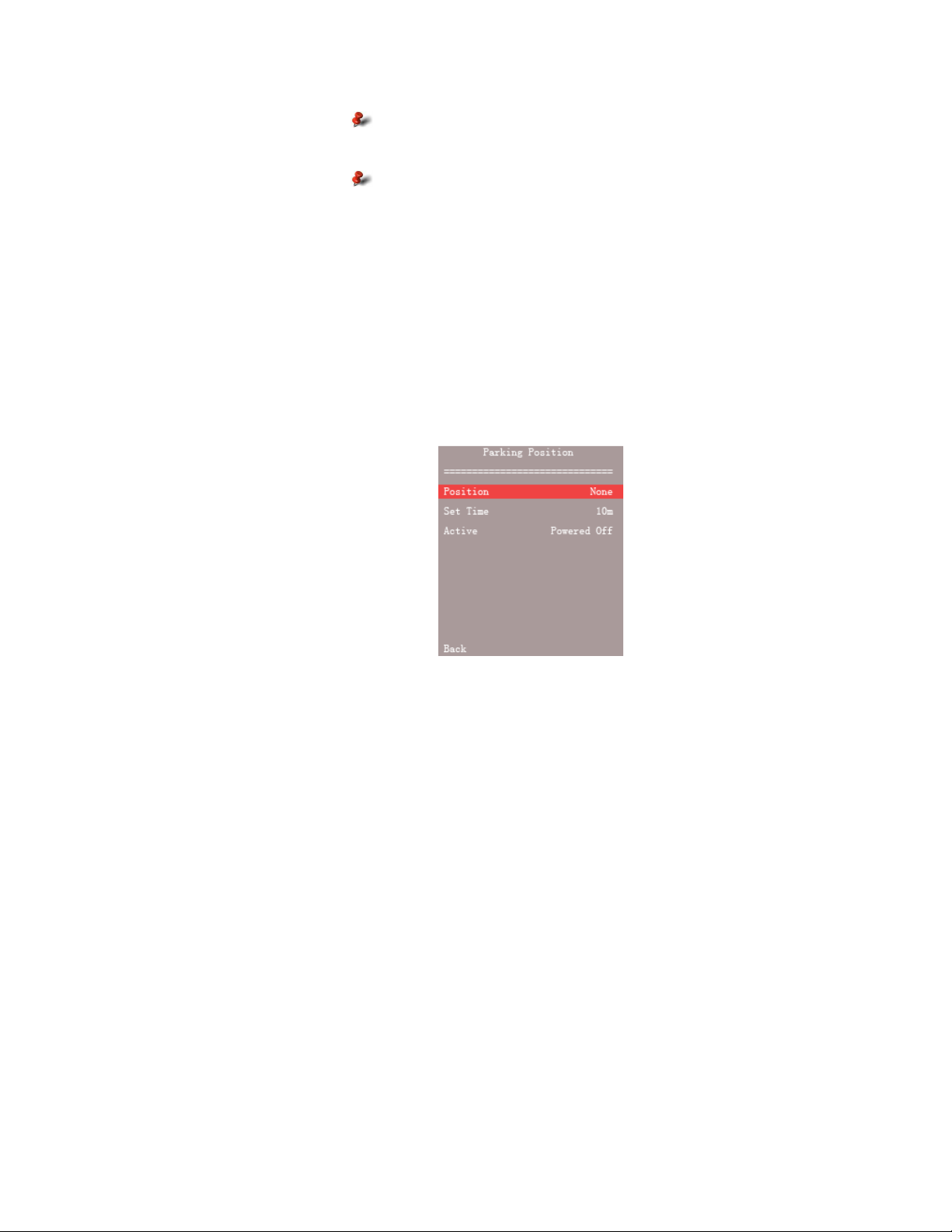
ComNav V5 Installation & Operation
Clear
Clear preset - when selected, “confirm” blinks in this position. Press “Accept” to clear the preset,
“Finish” appears and “Undefined” displays in preset state position. Press “Esc” to cancel clearing
the preset and to exit back to the menu.
Back
Go back to previous menu level
<Parking Position>
Note: when Gyro Stabilization option
is active, tilt preset position will not
be executed.
Note: Special preset cannot be
forced to run.
Figure 23 - Parking Position submenu
Parking position is executed with the use of a timing trigger. When the camera does not receive
any control commands for a set period of time, it executes a move to the defined position.
Position
This is the position the camera will move to when parking is initiated. Available settings are:
none, or any of the presets 001 – 008, provided they are defined. If None is set, the camera will
not move to any position.
Set Time
Set Idol Time interval for executing parking position procedure. It can be set to a period between
2 to 60 minutes.
Active
Activate parking position option. It can be set to “Powered On” (enabled) or “Powered OFF”.
SET HOME POSITION
Home position is considered the Zero position of the camera system. User can define a
customized home position through this menu.
Document PN 29010098 V1.0 - 46 -
Page 49

ComNav V5 Installation & Operation
To define a custom Home position, manually pan and tilt the camera system to point the
cameras to a desired direction. Then press “Accept” key to confirm the selected position to be
the home position.
For a fast HOME position programming, position the camera in the desired pan and tilt positions
and press and hold down the HOME button on the joystick until a programmed message can be
seen on the display (about 3 Seconds)
PROPORTIONAL PAN
Enable or Disable proportional pan. The Camera will move slower when camera is zoomed in
and will move faster when zoomed out.
Default setting: OFF
MOUNT MODE
Note: it is strongly recommended to define
the bow (head of vessel) as pan zero
position. This will enable accurate camera
position reading relative to the vessel’s
heading.
Allow the definition of image orientation for UP or DOWN mounting. Default setting is UP. A
Down setup will result in a flipped image.
V5 is only recommended for UP side mounting.
RESET REF ORIGIN
If there are drifts in movement during pan/tilt, users need to reset REF origin. When this item is
selected, the camera system will move to the optical coupler position on the pan and tilt axis to
align the camera back to its origin position. This help the camera find out its location and set a
reference point. This procedure is run every time the power is cycled to the camera.
Back
Go back to previous menu level.
<VIDEO SIGNAL> Submenu
Figure 24 - Video Signal in Main menu
Document PN 29010098 V1.0 - 47 -
Page 50
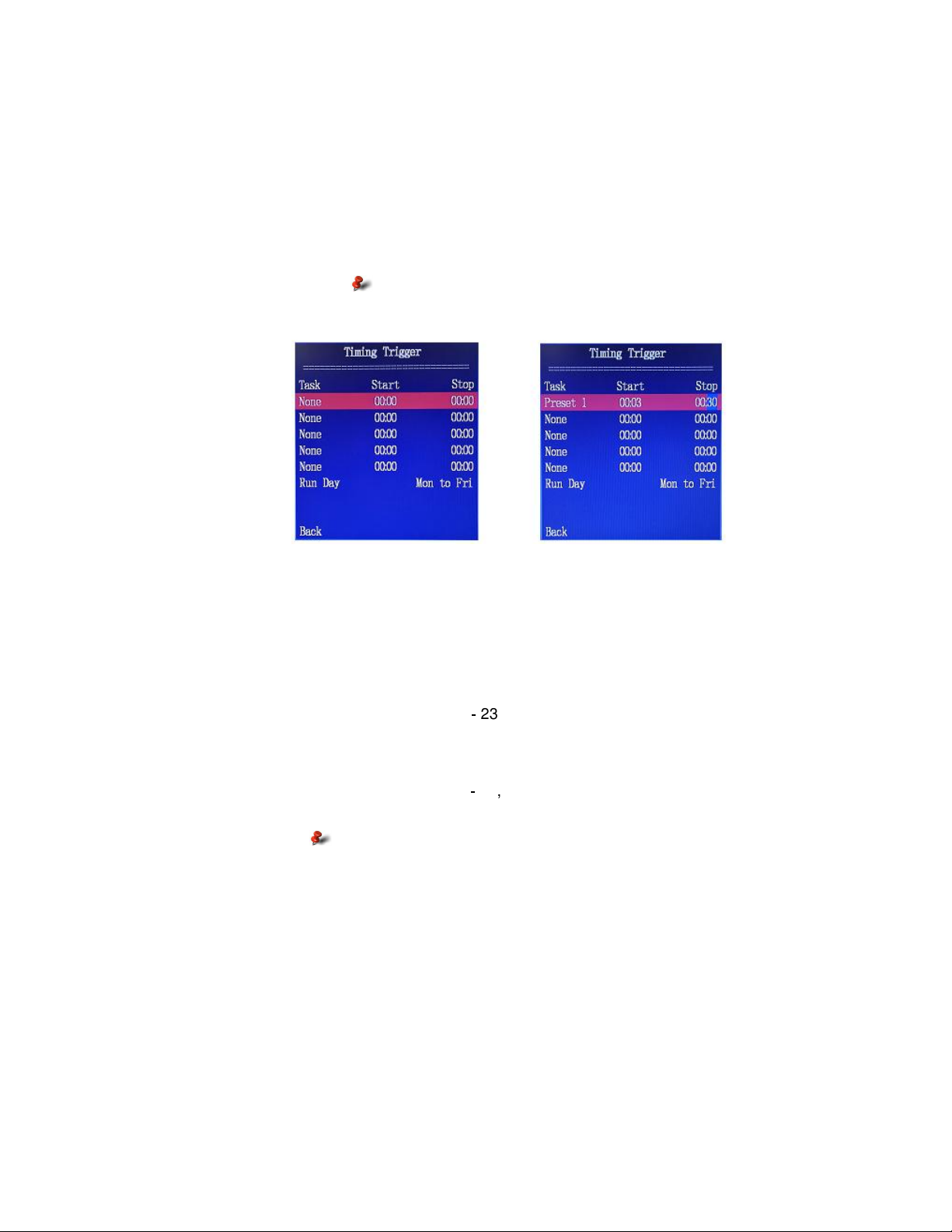
ComNav V5 Installation & Operation
Switch the video signal output between Thermal imager and LowLight cameras through the
menu.
At every power up, the signal from the lowlight camera is selected.
<TIMING TRIGGER> SUBMENU
The menu allows users to set up automatic tasks that will be run in specified time windows.
Upon entering the submenu, a list of tasks will be shown. In Figure 25, the left is an example of
an empty list; the right is a list with one defined task.
Note: time setting is in a 24 hour format
Figure 25 - Examples of time triggered task list
Task
Tasks can be set to: None, Preset 1 to Preset 8 or Auto scan. When “none” is set, no task is
executed when the timer is triggered.
Start
Trigger start time: Hour: Minute. (Hour1 - 23, Minute: 00 - 59)
Close
Trigger stop time: Hour: Minute. (Hour1 - 23, Minute: 00 - 59)
Important Notes:
1. Check system time for proper setting.
2. Time overlap of timing trigger ranges is not allowed.
3. Start time must be less than stop time.
4. After a parking position is completed, other task may be
executed.
5. When in the process of task operation, users may
interrupt the task manually. If no action is taken within
10 seconds, the system returns to the original task.
Run Day
Repetition setting: available settings are Monday to Friday, Monday to Saturday and Monday to
Sunday.
Document PN 29010098 V1.0 - 48 -
Page 51
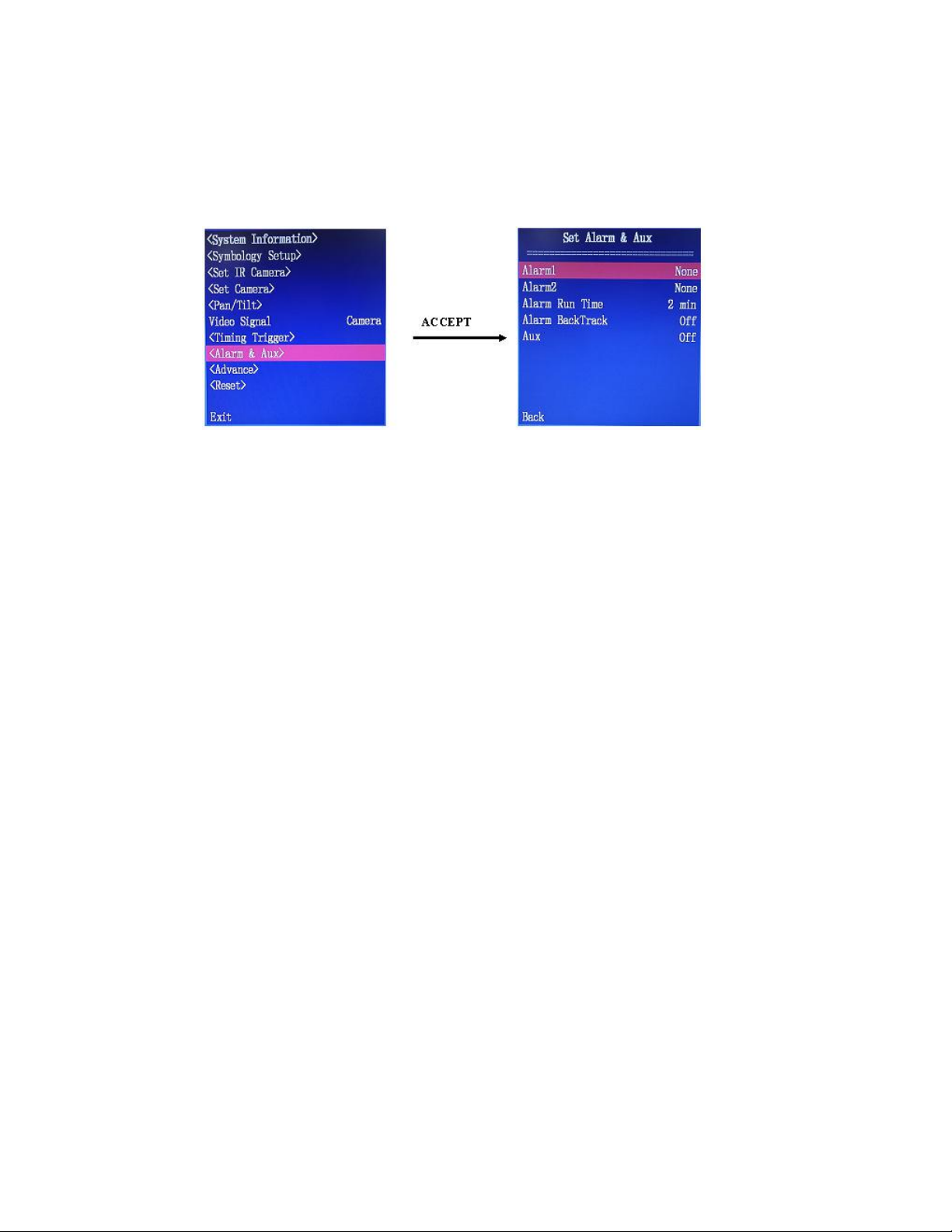
ComNav V5 Installation & Operation
<ALARM & AUX> SUBMENU
The camera has 2 external alarm inputs. This setup menu allows the user to select the action to
be taken when an alarm is detected. Specifically, which position to go to once the alarm is
triggered, and how long to continue if the alarm condition is not cleared.
Figure 26 - Set Alarms and Aux
Alarm1
The action the camera will take to when an alarm condition is detected at the first alarm input.
Available options are None, Preset 1 to Preset 8. When this item is set to None, no action will be
taken when the alarm is detected.
Default setting: None.
Alarm2
The action the camera will take to when an alarm condition is detected at the second alarm input.
Available options are None, Preset 1 to Preset 8. When this item is set to None, no action will be
taken when the alarm is detected.
Default setting: None.
Alarm Run Time:
This sets the time interval the Alarm1 or Alarm2 action will last. The options are Unlimited, 30
seconds, 1 minutes, 2 minutes, 3 minutes, 4 minutes, and 5 minutes.
When Alarm Run Time is set to Unlimited, the camera system will follow the preset action as
long as the alarm condition continues.
For all other options, after the triggered by an alarm condition, the camera system will follow the
preset action for the specified interval regardless the status of the alarm condition. At the end of
the time period, the camera may stop its motion, or go back to pre-alarm action depending on the
setting of Alarm Back Track.
Default setting: Unlimited
Alarm BackTrack
This setting defines the system’s behaviour after an alarm action stops. The options are On and
Off.
OFF keeps the camera at the current position waiting for a new command.
ON initiates a return back to the task or position condition occurred prior to an alarm trigger.
Default setting: OFF
Document PN 29010098 V1.0 - 49 -
Page 52
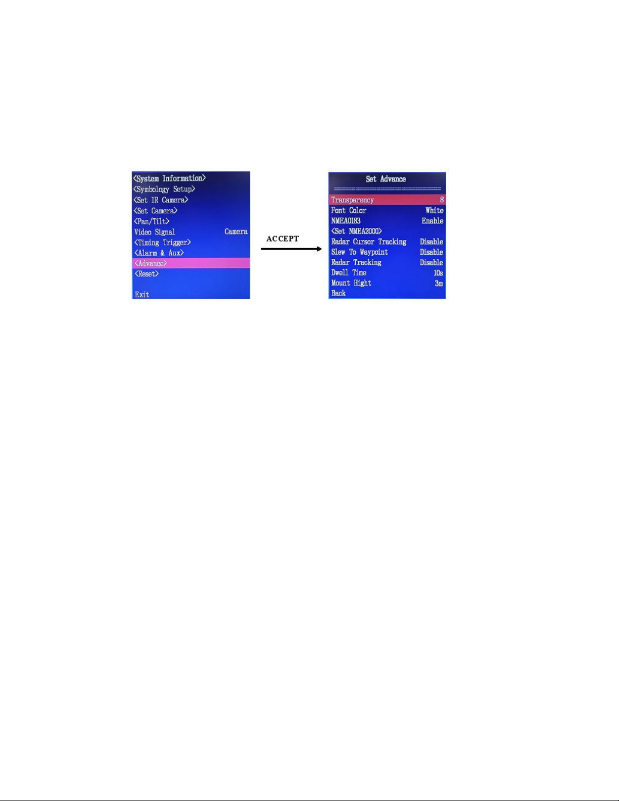
ComNav V5 Installation & Operation
Aux
Enable or disable an extra signal input for general or custom use.
Default setting: OFF.
<ADVANCE> SUBMENU
Settings for communication ports and miscellaneous items are in Advance submenu.
Figure 27 - Enter Advance Submenu
Transparency
This sets the setup menu transparency level. Selection range is between 0 – 63 with 0 being
100% transparent and 63 being 100% opaque.
Font Color
The Font Color is fixed as White and cannot be changed.
NMEA 0183
Enable or disable the NMEA 0183 input.
If this item is set to ON, the camera system will read the heading or radar messages in NMEA
0183 from its 2 NMEA 0183 ports.
Both ports can accept the heading and radar messages. Which port will be used depends on
which one receives a data type first. For example, if Port 1 receives a heading message before
Port 2, Port 1 will be used as the heading source.
The NMEA 2000 port has higher priority than NMEA 0183 ports. This means if headings are
received from NMEA 2000 port and NMEA 0183 port simultaneously, NMEA 2000 port will be
used as the heading source.
<Set NMEA 2000>
Use this menu to select an NMEA 2000 compass.
Document PN 29010098 V1.0 - 50 -
Page 53
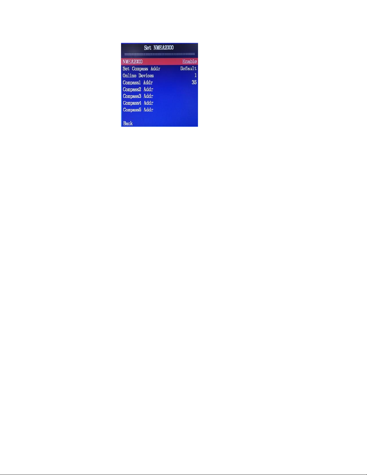
ComNav V5 Installation & Operation
NMEA 2000
Enable or disable NMEA 2000. NMEA 2000 port only reads PGN 127250.
Select Compass Addr
V5 camera system will monitor the NMEA 2000 but it connects to for PGN 127250. It reports the
number of addresses a PGN 127250 is received in Online Devices, and lists the addresses for
up to 5 devices. In the example of Figure 28, 1 device is found at address 35.
Users can set this item to any of the 5 listed addresses if available. V5 will use the device with
the selected address as the heading source.
The Select Compass Addr may also be set to Default. If the Default is selected, V5 will use the
device with the lowest address as the heading source.
Back
Go back to previous menu level.
Radar Cursor Tracking
This function is disabled for V5.
Figure 28 - NEMA 2000 menu
Slew To Way Point
This function is disabled for V5.
Radar Tracking
When this item is set to Enable, theV5 system will accept TTM sentence from a radar. Through
TTM V5 can track up to 100 targets, for each target the tracking will last a time period specified
in Dwell Time.
Dwell Time
A parameter used for Slew To Way Point function.
Mount Height
Set the distance from the V5 camera to the sea level. This value is important for the proper
function of radar tracking feature. The unit of this value is meter.
Document PN 29010098 V1.0 - 51 -
Page 54
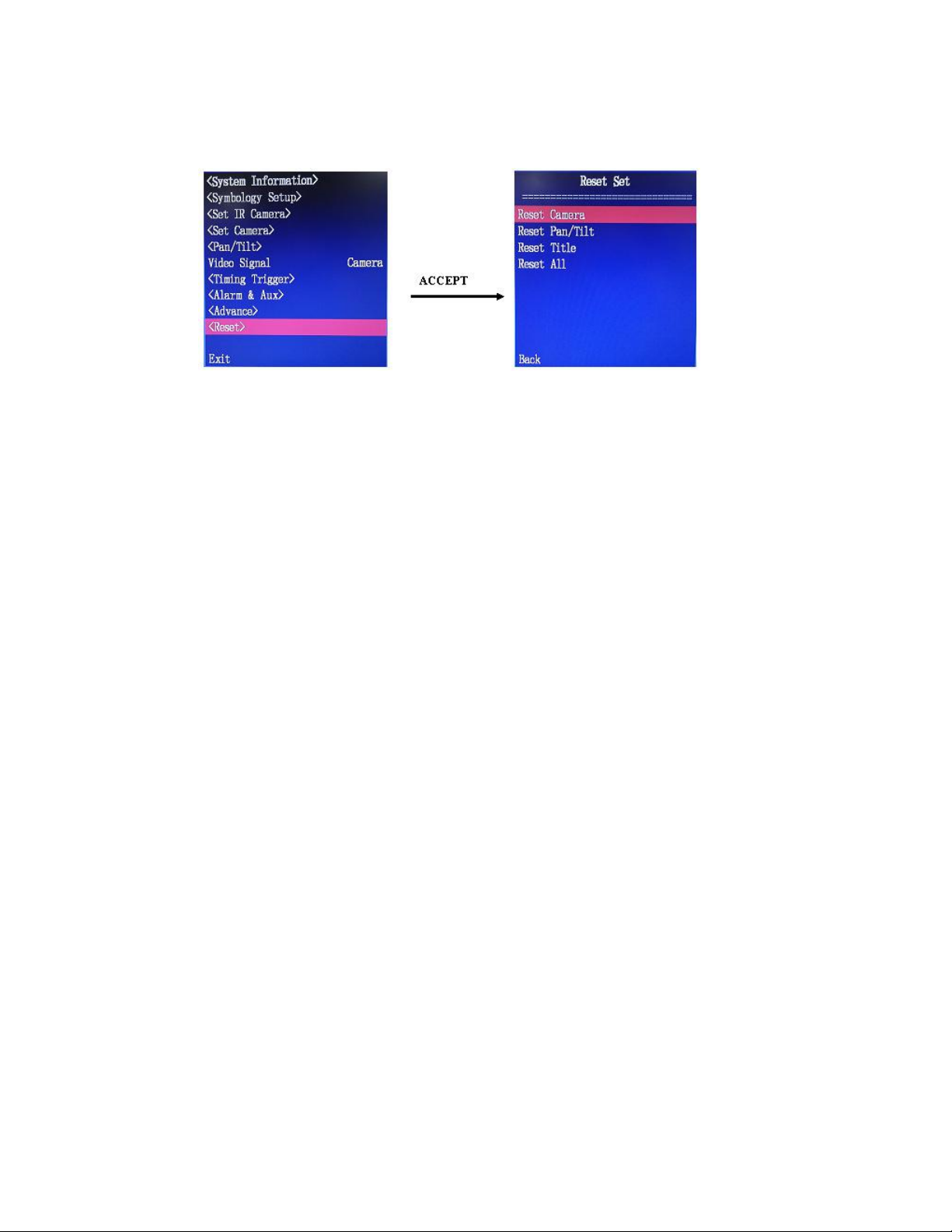
ComNav V5 Installation & Operation
<Reset> Submenu
Figure 29 - Enter Reset submenu
Reset Camera
Force all settings in the “Camera Set” menu to their factory defaults.
Reset Pan/Tilt
Force all settings in the “Pan/Tilt” menu to factory defaults. Presets are not affected.
Reset Title
User name and preset titles are set to default, all characters are deleted.
Reset All
Reset All includes the action of Reset Camera and Reset Pan/tilt. On top of these, it will also
turn the Home Position and other Preset positions to the defaults.
When Reset All is carried out, if the gyro stabilization system is active, it will be deactivated
automatically.
Back
Go back to previous menu level.
EXIT
Exit the main menu.
Document PN 29010098 V1.0 - 52 -
Page 55

ComNav V5 Installation & Operation
Care & Maintenance
Care & Maintenance
Care & MaintenanceCare & Maintenance
Document PN 29010098 V1.0 - 53 -
Page 56

ComNav V5 Installation & Operation
Document PN 29010098 V1.0 - 54 -
Page 57

ComNav V5 Installation & Operation
Care & Maintenance
The V5 Camera System has been designed to provide many years of reliable service. The
following care and maintenance tips will help to ensure the longevity of the equipment.
Protection of Wires and Cabling
After installation, ensure that the system’s components are securely mounted and will not
shake loose with the vibrations that are expected in a marine vessel.
Ensure that the cables to the equipment are well secured with clamps and/or alternative
fasteners.
Many potential problems can be avoided by ensuring that cables and wiring do not cause any
connectors strain.
Periodic Checks
After the first six months of operation, a thorough examination of the entire Camera system
MUST BE UNDERTAKEN. Verify that all electrical connections, cables, clamps, mounting
brackets, and mechanical connections are secure.
An annual inspection should be undertaken thereafter.
General Precautions
A few precautions will keep the unit in prime condition:
• The Camera and control enclosures do not require any special maintenance. An
occasional cleaning is suggested; use a damp cloth and mild soap.
Note: Do not use abrasive cleaners or chemicals. Improper
Care can cause damage to the lens cover coating, degrade the
camera’s performance and may void the warranty.
• Avoid exposing the enclosure to solvents, acids, and bases – some of these may
weaken the plastic.
• The Camera and control enclosures are designed to be weatherproof and splash
resistant, Do not immersed in water.
• Avoid environments exceeding a temperature of 85°C or below -40°C.
Repair
There are no user serviceable parts inside the Camera or controller enclosures. Should the
unit become damaged in any way, Contact an authorized ComNav dealer.
Fuse Replacement
There are no fuses used inside the camera or controller unit. However, it is strongly
recommended that a fuse (or circuit breaker) be used when installing the equipment.
Note: If the fuse/breaker blows, determine the cause before
replacing or resetting
Cleaning
Clean the camera window only with low-pressure fresh water and a soft cloth. For water
spots, wipe the lens cover with a clean, fresh water dampened lens cloth.
Document PN 29010098 V1.0 - 55 -
Page 58

ComNav V5 Installation & Operation
Document PN 29010098 V1.0 - 56 -
Page 59

ComNav V5 Installation & Operation
Appendices
Appendices
AppendicesAppendices
Document PN 29010098 V1.0 - 57 -
Page 60

ComNav V5 Installation & Operation
Document PN 29010098 V1.0 - 58 -
Page 61
ComNav V5 Installation & Operation Technical Information
Horizontal View
Appendix 1
Specifications
Part Number 21610026 21610027
Description
Field of View
(FOV)
Thermal Engine
Thermal
Sensitivity
Pixel Pitch
Spectral
Response
D.R.I Ranges
Pan / Tilt Range
Pan / Tilt Speed
Color Palettes /
Dual Camera System 9Hz Frame Rate Resolution:
640x480
Dual Camera System 30Hz Frame Rate Resolution:
640x480
200 horizontal, 150 Vertical
TECcooled Amorphous Silicone (a-Si) Microbolometer Thermal Core
<40mK <40mK
23.5µ 23.5µ
8µm ~ 14µm 8µm ~ 14µm
~2000+M (2.3X2.3 Object) ~2000+M (2.3X2.3 Object)
Pan: 360˚ continuous - Tilt: +90˚
Pan:0-40˚/sec - Tilt: 0-20˚/sec
CUSTOM、INFERNO、SOFT LIGHT、ARCUS、FULL SPECTRUM、 MEMORIAM 、 OCEAN
with White Hot and Black Hot
Gyro
Stabilization
Static Accuracy: less than 0.50, Dynamic Accuracy: less than 20
Accuracy
Zoom Range
x1.0 to x4.0 (0.1 step increments)
Display
Processing
Temperature
Measurement
Centre point, accuracy of + 150C or + 15%
LowLight
Engine
Angle (lowlight)
Zoom
Document PN 29010098 V1.0 - 59 -
Optical zoom: 36X, Digital Zoom: 12X ( 432X total zoom)
Wide Angle: 570, Narrow Angle: 1.70
Flip Image, ICE, 3D filter
1/4 “ HAD CCD
Page 62
ComNav V5 Installation & Operation Technical Information
Lens
Protection
Certification /
Compliance
Telemetry
F1.6-4.5, (F34mm – 122.4mm)
Lighting and Surge circuit protection
CE, FCC, RoHs
Pelco D / ComNav Propriety Protocol
Table 4 – Thermal Camera System Receiver Specifications
System Interface
Parameter Specification
Communication
Baud Rate 4800, 9600(default), 19200 and 38400
Video Output 1X BNC 1V P-P / 75Ω Composite
Table 5 – System Interface Specifications
• RS-422 Full Duplex; Pelco D/P
Power
Parameter Specification
Supply Voltage 12VDC or 24 VDC, 48W max.
Power Consumption 50 W Max, with heater operating
Table 6 – Power Specifications
Mechanical
Parameter Specification
Dimensions 40 cm (H) x 23.4 cm (D)
(15.75 in. x 9.21in.) not including mount
Weight 10 Kg
Enclosure Rating IP 67
Operating Temperature -25°C to +80°C
Storage Temperature -40°C to +85°C
Relative Humidity 5% to 90%
Shock Resistance
Vibration Resistance
Compliance CE , FCC, RoHS
Lens 30mm Motorized Lens
Data cable length
Table 7 – Mechanical Specifications
Vertical: 15G, Horizontal: 9G
CE compliance
• standard:
o 15 metres (50 feet),
(custom and other lengths are available)
Document PN 29010098 V1.0 - 60 -
Page 63

ComNav V5 Installation & Operation Ordering
Appendix 2
Ordering Information
Part #
11610028
11610029
21610021
21610026
21610027
21610019
31610055
31610046
31610048
31610050
31610038
31610052
31610053
31610054
31610045
31610043
31610027
31610061
31610029
29010098
V5 GYRO STABILIZED DUAL CAMERA
V5 Dual Camera (Thermal and LowLight), c/w JCU, flush mount plate & hardware – 9Hz Frame rate
V5 Dual Camera (Thermal and LowLight), c/w JCU, flush mount plate & hardware – 30Hz frame rate.
V5 ACCESSORIES
V5 Second Station, c/w Joystick Controller, Mounting hardware, trim, rubber gasket, and Splitter Switch
Box
V5 Dual Camera (Thermal and LowLight), 9Hz, 640x480, c/w flush mount plate & hardware. 35mm lens.
V5 Dual Camera (Thermal and LowLight), 30Hz, 640x480, c/w flush mount plate & hardware. 35mm lens.
Joystick controller, c/w Mounting hardware, trim and rubber gasket
Multi system splitter switch
50Ft extension Power cable for V Series Dual Camera System
50Ft extension Video cable for V Series Dual Camera System
50Ft extension Cat5 Controller cable for V Series Dual Camera System
Flush Mount Plate Kit
Pole Adaptor Mount Plate for V Series Dual Camera System
Mast Side Mount (Swivel) Mount Platform For V Series Dual Camera System
Leaning Post Mount Arm Bracket For V Series Dual Camera System
Joystick controller cover
Camera mounting Hardware Pkg
7" Combined Waterproof Monitor/4 Channel Quad Splitter
ComNav Network Box / Furuno NAVNET Interface
4 Channel Digital Video Recorder, 250GB
Installation & Operation Manual
Document PN 29010098 V1.0 - 61 -
Page 64
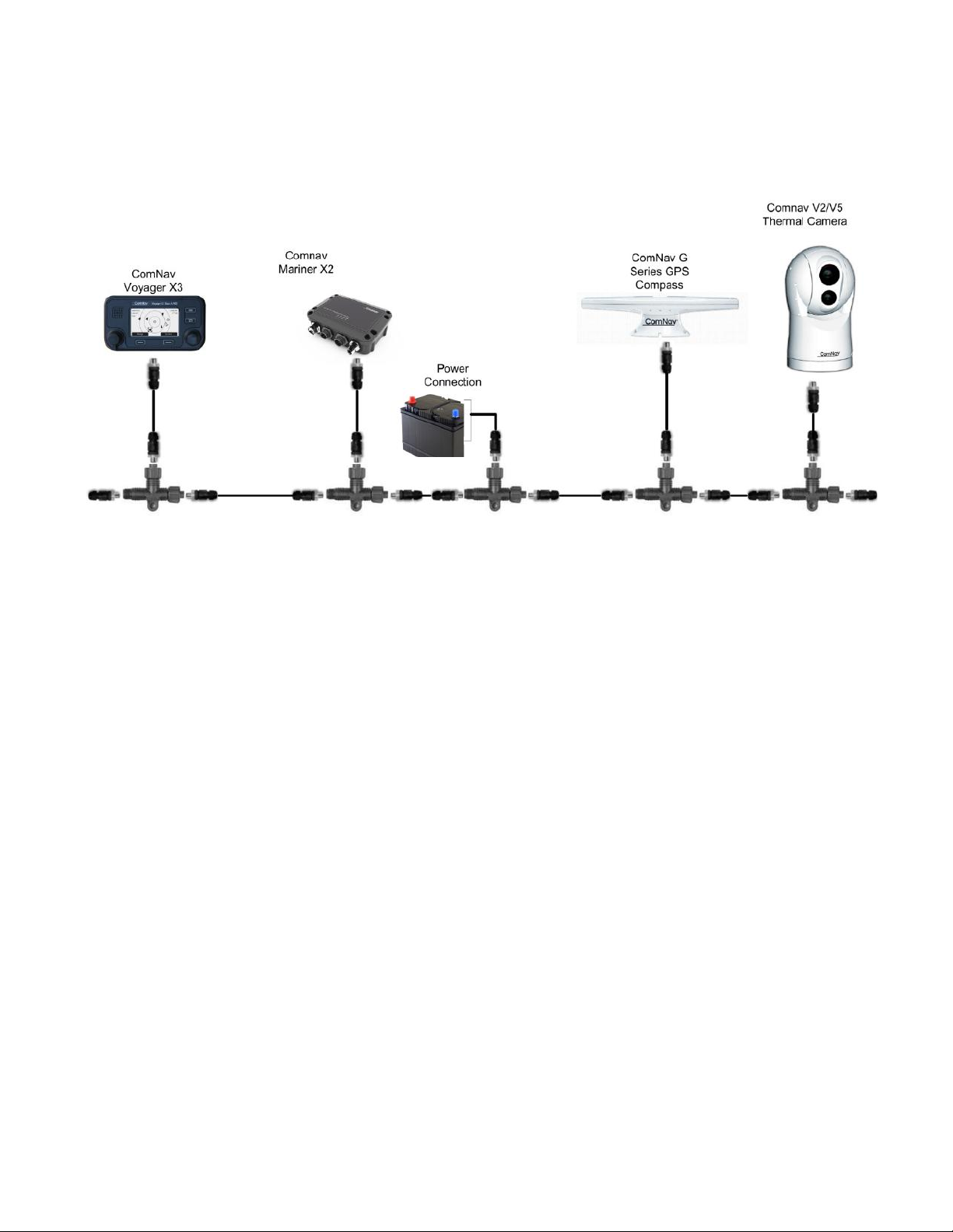
ComNav V5 Installation & Operation Warranty
Appendix 3
NMEA 2000 Setup Example
General Notes:
• If an NMEA2000 network system is not present, contact a qualified installer to setup the NMEA2000
network. The network requires proper connection to account for voltage drop based on cable resistance,
distance or length of cables and network load.
• No more than 2 terminators should be used in the network.
• Total distance between any 2 points on the network cannot exceed 100M (328 Ft).
• The length of a single drop cable cannot exceed 6M (19.7 Ft).
• Total devices connected to the network cannot exceed 50.
Document PN 29010098 V1.0 - 62 -
Page 65

ComNav V5 Installation & Operation Warranty
Appendix 4
Common Problems and Correct Actions
No display on the screen
1. Check the power line is correctly connected and the power supply is on
2. Check the video signal line is properly connected
3. Check if the Pan-tilt system is in Standby mode. In Standby Mode, there is no video output (see the
description of Power button).
To verify if the Pan-tilt system in under Standby mode, use the Joystick to pan or tilt the camera. In
Standby mode, the camera position cannot be controlled by the Joystick. Therefore, if the camera
moves, the system is NOT in Standby mode
If all cables are well connected, and the system in normal operation mode, internal circuits may be
damaged.
Images on the display flash in and out
Check if the video signal line is firmly connected.
Make sure the camera system is out of the path of strong electromagnetic fields, such as near a radar
system
Images are not clear when using maximum zoom
Check if you have turned on electronic zoom
Check if objects are too close to the camera for a good focus
Images are shaking under maximum zoom
Check if the system is firmly mounted. Make sure there is no vibration source close to the mounting base.
Thermal image has high spot noises
ICE value may be too high. Reduce ICE Strength from <ICE> menu
Perform thermal core calibration through Do Calibration in <Field Calibrate> menu to reduce the
background noise
If the environment temperature is high, set Period Set in <Field Calibration> menu to 30 min or less so
that the camera will automatically calibrate itself.
Low Light Camera has high noises
Sharpness Level may be too high. Reduce the value in <Set Camera> menu. This value is set to 10 out
of factory.
Cannot switch between the low light camera and the IR camera
First make sure the video cables are well connected.
If you cannot switch cameras through the IR/CAM button, try to switch the video sources through the
menu. If you can switch the cameras through the menu, the IR/CAM button may be broken.
Document PN 29010098 V1.0 - 63 -
Page 66

ComNav V5 Installation & Operation Warranty
Pressing STAB button does turn on Gyro stabilization
Check if all cables are well connected
Check the controller has selected the correct camera address. The camera address will be displayed on
the screen if the SELECT button is pressed and held for over 3 seconds.
If the problem still persists, the STAB button may be broken, or the gyro may be damaged
Compass icon on the screen points to a wrong direction
Check you have a compass connected to the system
Check your compass provides the right output format (NMEA 0183 or NMEA 2000)
Check you have selected the correct heading protocol that matches your compass’ output
Heading on the screen shows a wrong value Hdg: 0
Check if your NMEA 0183 compass works correct.
Check NMEA 0183 connections at both ports
Restart your compass
Restart your V5
Multiplex camera systems react to my control when I want to control only one system
These camera systems may have the same address. Change them to different values
Joystick cannot control the dual camera system
Check the Joystick is correctly installed and connected to the camera systems
Check the correct camera address is selected
Check if “Active” is seen on the joystick LCD
Document PN 29010098 V1.0 - 64 -
Page 67

ComNav V5 Installation & Operation Warranty
End User License Agreement
IMPORTANT - This is an agreement (the "Agreement") between you, the end purchaser ("Licensee") and ComNav Marine Ltd.
("ComNav") which permits Licensee to use the ComNav software (the "Software") that accompanies this Agreement. This Software may be
licensed on a standalone basis or may be embedded in a Product. Please read and ensure that you understand this Agreement before
installing or using the Software Update or using a Product.
In this agreement any product that has Software embedded in it at the time of sale to the Licensee shall be referred to as a "Product". As
well, in this Agreement, the use of a Product shall be deemed to be use of the Software which is embedded in the Product.
BY INSTALLING OR USING THE SOFTWARE UPDATE OR THE PRODUCT, LICENSEE THEREBY AGREES TO BE LEGALLY BOUND BY THE TERMS
OF THIS AGREEMENT. IF YOU DO NOT AGREE TO THESE TERMS, (I) DO NOT INSTALL OR USE THE SOFTWARE, AND (II) IF YOU ARE
INSTALLING AN UPDATE TO THE SOFTWARE, DO NOT INSTALL THE UPDATE AND PROMPTLY DESTROY IT.
COMNAV PROVIDES LIMITED WARRANTIES IN RELATION TO THE SOFTWARE. AS WELL, THOSE WHO USE THE EMBEDDED SOFTWARE DO
SO AT THEIR OWN RISK. YOU SHOULD UNDERSTAND THE IMPORTANCE OF THESE AND OTHER LIMITATIONS SET OUT IN THIS AGREEMENT
BEFORE INSTALLING OR USING THE SOFTWARE OR THE PRODUCT.
1. LICENSE. ComNav hereby grants to Licensee a non-transferable and non-exclusive license to use the Software as embedded in a
Product and all Updates (collectively the "Software"), solely in binary executable form.
2. RESTRICTIONS ON USE. Licensee agrees that Licensee and its employees will not directly or indirectly, in any manner whatsoever:
a. install or use more copies of the Software than the number of copies that have been licensed;
b. use or install the Software in connection with any product other than the Product the Software was intended to be used or
installed on as set out in the documentation that accompanies the Software.
c. copy any of the Software or any written materials for any purpose except as part of Licensee's normal backup processes;
d. modify or create derivative works based on the Software;
e. sub-license, rent, lease, loan or distribute the Software;
f. permit any third party to use the Software;
g. use or operate Product for the benefit of any third party in any type of service outsourcing, application service, provider service
or service bureau capacity;
h. reverse engineer, decompile or disassemble the Software or otherwise reduce it to a human perceivable form;
i. Assign this Agreement or sell or otherwise transfer the Software to any other party except as part of the sale or transfer of the
whole Product.
3. UPDATES. At ComNav's discretion ComNav may make Updates available to Licensee. An update ("Update") means any update to the
Software that is made available to Licensee including error corrections, enhancements and other modifications. Licensee may access,
download and install Updates during the Warranty Period only. All Updates that Licensee downloads, installs or uses shall be deemed
to be Software and subject to this Agreement. ComNav reserves the right to modify the Product without any obligation to notify,
supply or install any improvements or alterations to existing Software.
4. SUPPORT. ComNav may make available directly or through its authorized dealers telephone and email support for the Software.
Contact ComNav to find the authorized dealer near you. As well, ComNav may make available user and technical documentation
regarding the Software. ComNav reserves the right to reduce and limit access to such support at any time.
5. BACKUPS AND RECOVERY. Licensee shall back-up all data used, created or stored by the Software on a regular basis as necessary to
enable proper recovery of the data and related systems and processes in the event of a malfunction in the Software or any loss or
corruption of data caused by the Software. Licensee shall assume all risks of loss or damage for any failure to comply with the
foregoing.
6. OWNERSHIP. The Licensee understands that the Licensee does NOT own rights, title and interest in and to the Software and related
materials, including intellectual property rights. The Software is licensed to Licensee, not sold.
7. TRADEMARKS. "ComNav” and the associated logos are trademarks of ComNav. Other trademarks are the property of their respective
owners. Licensee may not use any of these trademarks without the consent of their respective owners.
8. LIMITED WARRANTY. ComNav warrants solely to the Licensee, subject to the exclusions and procedures set forth herein below,
that for a period of two (2) years from the original date of purchase of the Product in which it is embedded (the "Warranty
Period"), the Software, under normal use and maintenance, will conform in all material respects to the documentation provided
with the Software and any media will be free of defects in materials and workmanship. For any Update, ComNav warrants, for 90
days from performance or delivery, or for the balance of the original Warranty Period, whichever is greater, that the Update,
under normal use and maintenance, will conform in all material respects to the documentation provided with the Update and
any media will be free of defects in materials and workmanship. Notwithstanding the foregoing, ComNav does not warrant that
the Software will meet Licensee's requirements or that its operation will be error free.
Document PN 29010098 V1.0 - 65 -
Page 68

ComNav V5 Installation & Operation Warranty
9. WARRANTY EXCLUSIONS. The warranty set forth in Section (8) will not apply to any deficiencies caused by (a) the Product not
being used as described in the documentation supplied to Licensee, (b) the Software having been altered, modified or converted
in any way by anyone other than ComNav or approved by ComNav, (c) any malfunction of Licensee's equipment or other
software, or (d) damage occurring in transit or due to any accident, abuse, misuse, improper installation, lightning (or other
electrical discharge) or neglect other than that caused by ComNav. ComNav GPS does not warrant or guarantee the precision or
accuracy of positions obtained when using the Software (whether standalone or embedded in a Product). The Product and the
Software is not intended and should not be used as the primary means of navigation or for use in safety of life applications. The
potential positioning and navigation accuracy obtainable with the Software as stated in the Product or Software documentation
serves to provide only an estimate of achievable accuracy based on specifications provided by the US Department of Defense for
GPS positioning and DGPS service provider performance specifications, where applicable.
10. WARRANTY DISCLAIMER. EXCEPT AS EXPRESSLY SET OUT IN THIS AGREEMENT, COMNAV MAKES NO REPRESENTATION,
WARRANTY OR CONDITION OF ANY KIND TO LICENSEE, WHETHER VERBAL OR WRITTEN AND HEREBY DISCLAIMS ALL
REPRESENTATIONS, WARRANTIES AND CONDITIONS OF ANY KIND INCLUDING FITNESS FOR A PARTICULAR PURPOSE,
MERCHANTABILITY, ACCURACY, RELIABILITY OR THAT THE USE OF THE SOFTWARE WILL BE UNINTERRUPTED OR ERROR-FREE
AND HEREBY DISCLAIMS ALL REPRESENTATIONS, WARRANTIES AND CONDITIONS ARISING AS A RESULT OF CUSTOM, USAGE OR
TRADE AND THOSE ARISING UNDER STATUTE.
11. LIMITS ON WARRANTY DISCLAIMER. Some jurisdictions do not allow the exclusion of implied warranties or conditions, so some
of the above exclusions may not apply to Licensee. In that case, any implied warranties or conditions which would then
otherwise arise will be limited in duration to ninety (90) days from the date of the license of the Software or the purchase of the
Product. The warranties given herein give Licensee specific legal rights and Licensee may have other rights which may vary from
jurisdiction to jurisdiction.
12. CHANGE TO WARRANTY. No employee or agent of ComNav is authorized to change the warranty provided or the limitation or
disclaimer of warranty provisions. All such changes will only be effective if pursuant to a separate agreement signed by senior
officers of the respective parties.
13. WARRANTY CLAIM. In the event Licensee has a warranty claim Licensee must first check for and install all Updates that are made
available. The warranty will not otherwise be honored. Proof of purchase may be required. ComNav does not honor claims
asserted after the end of the Warranty Period.
14. LICENSEE REMEDIES. In all cases which involve a failure of the Software to conform in any material respect to the documentation
during the Warranty Period or a breach of a warranty, ComNav's sole obligation and liability, and Licensee's sole and exclusive
remedy, is for ComNav, at ComNav's option, to (a) repair the Software, (b) replace the Software with software conforming to the
documentation, or (c) if ComNav is unable, on a reasonable commercial basis, to repair the Software or to replace the Software
with conforming software within ninety (90) days, to terminate this Agreement and thereafter Licensee shall cease using the
Software. ComNav will also issue a refund for the price paid by Licensee less an amount on account of amortization, calculated
on a straight-line basis over a deemed useful life of three (3) years.
15. LIMITATION OF LIABILITY. IN NO EVENT WILL COMNAV BE LIABLE TO LICENSEE FOR ANY INCIDENTAL, CONSEQUENTIAL, SPECIAL
OR INDIRECT DAMAGES INCLUDING ARISING IN RELATION TO ANY LOSS OF DATA, INCOME, REVENUE, GOODWILL OR
ANTICIPATED SAVINGS EVEN IF COMNAV HAS BEEN INFORMED OF THE POSSIBILITY OF SUCH LOSS OR DAMAGE. FURTHER, IN NO
EVENT WILL COMNAV'S TOTAL CUMULATIVE LIABILITY HEREUNDER, FROM ALL CAUSES OF ACTION OF ANY KIND, EXCEED THE
TOTAL AMOUNT PAID BY LICENSEE TO COMNAV TO PURCHASE THE PRODUCT. THIS LIMITATION AND EXCLUSION APPLIES
IRRESPECTIVE OF THE CAUSE OF ACTION, INCLUDING BUT NOT LIMITED TO BREACH OF CONTRACT, NEGLIGENCE, STRICT
LIABILITY, TORT, BREACH OF WARRANTY, MISREPRESENTATION OR ANY OTHER LEGAL THEORY AND WILL SURVIVE A
FUNDAMENTAL BREACH.
16. LIMITS ON LIMITATION OF LIABILITY. Some jurisdictions do not allow for the limitation or exclusion of liability for incidental or
consequential damages, so the above limitation or exclusion may not apply to Licensee and Licensee may also have other legal
rights which may vary from jurisdiction to jurisdiction.
17. BASIS OF BARGAIN. Licensee agrees and acknowledges that ComNav has set its prices and the parties have entered into this
Agreement in reliance on the limited warranties, warranty disclaimers and limitations of liability set forth herein, that the same
reflect an agreed-to allocation of risk between the parties (including the risk that a remedy may fail of its essential purpose and
cause consequential loss), and that the same forms an essential basis of the bargain between the parties. Licensee agrees and
acknowledges that ComNav would not have been able to sell the Product at the amount charged on an economic basis without
such limitations.
18. PROPRIETARY RIGHTS INDEMNITY. ComNav shall indemnify, defend and hold harmless Licensee from and against any and all
actions, claims, demands, proceedings, liabilities, direct damages, judgments, settlements, fines, penalties, costs and expenses,
including royalties and attorneys' fees and related costs, in connection with or arising out of any actual infringement of any third
party patent, copyright or other intellectual property right by the Software or by its use, in accordance with this Agreement and
documentation, PROVIDED THAT: (a) ComNav has the right to assume full control over any action, claim, demand or proceeding,
(b) Licensee shall promptly notify ComNav of any such action, claim, demand, or proceeding, and (c) Licensee shall give ComNav
such reasonable assistance and tangible material as is reasonably available to Licensee for the defense of the action, claim,
Document PN 29010098 V1.0 - 66 -
Page 69

ComNav V5 Installation & Operation Warranty
demand or proceeding. Licensee shall not settle or compromise any of same for which ComNav has agreed to assume
responsibility without ComNav's prior written consent. Licensee may, at its sole cost and expense, retain separate counsel from
the counsel utilized or retained by ComNav.
19. INFRINGEMENT. If use of the Software may be enjoined due to a claim of infringement by a third party then, at its sole discretion
and expense, ComNav may do one of the following: (a) negotiate a license or other agreement so that the Product is no longer
subject to such a potential claim, (b) modify the Product so that it becomes non-infringing, provided such modification can be
accomplished without materially affecting the performance and functionality of the Product, (c) replace the Software, or the
Product, with non-infringing software, or product, of equal or better performance and quality, or (d) if none of the foregoing can
be done on a commercially reasonable basis, terminate this license and Licensee shall stop using the Product and ComNav shall
refund the price paid by Licensee less an amount on account of amortization, calculated on a straight-line basis over a deemed
useful life of three (3) years.
The foregoing sets out the entire liability of ComNav and the sole obligations of ComNav to Licensee in respect of any claim that
the Software or its use infringes any third party rights.
20. INDEMNIFICATION. Except in relation to an infringement action, Licensee shall indemnify and hold ComNav harmless from any
and all claims, damages, losses, liabilities, costs and expenses (including reasonable fees of lawyers and other professionals)
arising out of or in connection with Licensee's use of the Product, whether direct or indirect, including without limiting the
foregoing, loss of data, loss of profit or business interruption.
21. TERMINATION. Licensee may terminate this Agreement at any time without cause. ComNav may terminate this Agreement on
30 days notice to Licensee if Licensee fails to materially comply with each provision of this Agreement unless such default is
cured within the 30 days. Any such termination by a party shall be in addition to and without prejudice to such rights and
remedies as may be available, including injunction and other equitable remedies. Upon receipt by Licensee of written notice of
termination from ComNav or termination by Licensee, Licensee shall at the end of any notice period (a) cease using the Software;
and (b) return to ComNav (or destroy and provide a certificate of a Senior Officer attesting to such destruction) the Software and
all related material and any magnetic or optical media provided to Licensee. The provisions of Sections 6), 7), 8), 9), 10), 15), 21),
26) and 27) herein shall survive the expiration or termination of this Agreement for any reason.
22. EXPORT RESTRICTIONS. Licensee agrees that Licensee will comply with all export control legislation of Canada, the United States,
Australia and any other applicable country's laws and regulations, whether under the Arms Export Control Act, the International
Traffic in Arms Regulations, the Export Administration Regulations, the regulations of the United States Departments of
Commerce, State, and Treasury, or otherwise as well as the export control legislation of all other countries.
23. PRODUCT COMPONENTS. The Product may contain third party components. Those third party components may be subject to
additional terms and conditions. Licensee is required to agree to those terms and conditions in order to use the Product.
24. FORCE MAJEURE EVENT. Neither party will have the right to claim damages as a result of the other's inability to perform or any
delay in performance due to unforeseeable circumstances beyond its reasonable control, such as labor disputes, strikes,
lockouts, war, riot, insurrection, epidemic, Internet virus attack, Internet failure, supplier failure, act of God, or governmental
action not the fault of the non-performing party.
25. FORUM FOR DISPUTES. The parties agree that the courts located in Vancouver, BC, Canada and the courts of appeal there from
will have exclusive jurisdiction to resolve any disputes between Licensee and ComNav concerning this Agreement or Licensee's
use or inability to use the Software and the parties hereby irrevocably agree to attorn to the jurisdiction of those courts.
Notwithstanding the foregoing, either party may apply to any court of competent jurisdiction for injunctive relief.
26. APPLICABLE LAW. This Agreement shall be governed by the laws of the Province of British Columbia, Canada, exclusive of any of
its choice of law and conflicts of law jurisprudence.
27. CISG. The United Nations Convention on Contracts for the International Sale of Goods will not apply to this Agreement or any
transaction hereunder.
28. GENERAL. This is the entire agreement between Licensee and ComNav relating to the Product and Licensee's use of the same,
and supersedes all prior, collateral or contemporaneous oral or written representations, warranties or agreements regarding the
same. No amendment to or modification of this Agreement will be binding unless in writing and signed by duly authorized
representatives of the parties. Any and all terms and conditions set out in any correspondence between the parties or set out in
a purchase order which are different from or in addition to the terms and conditions set forth herein, shall have no application
and no written notice of same shall be required. In the event that one or more of the provisions of this Agreement is found to be
illegal or unenforceable, this Agreement shall not be rendered inoperative but the remaining provisions shall continue in full
force and effect.
Document PN 29010098 V1.0 - 67 -
Page 70

ComNav V5 Installation & Operation Warranty
Warranty Information
Limited Warranty
This Limited Warranty (the “Warranty”) covers all V Series Camera products & accessories (the
“Equipment”) sold by ComNav Marine Ltd. (“ComNav”).
LIMITED ONE YEAR WARRANTY
ComNav warrants to the Purchaser, provided that the recommended installation and maintenance
procedures set forth in the manual (the “Manual”) provided with the Equipment have been followed,
and subject always to the other provisions of this Warranty, that the Equipment is free from defects in
workmanship and materials under normal use and service for a period of one (1) year from the date of
purchase of the Equipment by the Purchaser.
EXCLUSIONS
This Limited Warranty is null and void if:
1. The serial number of the Equipment has been removed, altered or mutilated;
2. Any of the anti-tamper seals covering case-screw holes, or other mechanisms for opening the
Equipment’s case, have been removed, broken or otherwise tampered with;
3. There are any defects in it, or damages to it, caused by:
a. Faulty installation or hook-up of the Equipment;
b. Abuse, misuse, or any use of the Equipment in violation of the instructions set forth in the
Manual;
c. Shipping, alterations, or incorrect and/or unauthorized service;
d. Accident, exposure of the Equipment to excessive heat, fire, lightning or other electrical
discharge, or water immersion;
e. Water damage due to failure to fully fasten the plug connected into the equipment’s
power/signal receptacle;
f. Improper or inadequate ancillary or connected equipment.
OTHER LIMITATIONS AND EXCLUSIONS
1. The Equipment is not intended for primary navigation or for use in safety of life applications;
ComNav does not warrant or guarantee that the Equipment will perform in accordance with the
requirements of such usage;
2. ComNav reserves the right to modify the Equipment without any obligation to notify, supply or
install any improvements or alterations to existing Equipment.
NO OTHER WARRANTIES
THE FOREGOING WARRANTY IS EXCLUSIVE OF ALL OTHER WARRANTIES AND
CONDITIONS, WHETHER WRITTEN, ORAL OR IMPLIED, ARISING BY STATUTE OR
OTHERWISE, WITH RESPECT TO THE DESIGN, SALE, INSTALLATION OR USE OF THE
Document PN 29010098 V1.0 - 68 -
Page 71

ComNav V5 Installation & Operation Warranty
EQUIPMENT, INCLUDING BUT NOT LIMITED TO IMPLIED WARRANTIES OR CONDITIONS
OF MERCHANTABILITY AND FITNESS FOR THE ORDINARY PURPOSES FOR WHICH THE
EQUIPMENT IS USED OR FITNESS FOR A PARTICULAR PURPOSE, AND ANY OTHER
OBLIGATIONS ON THE PART OF COMNAV, ITS EMPLOYEES, SUPPLIERS, AGENTS, OR
REPRESENTATIVES.
LIMITATION OF LIABILITY
The extent of ComNav’s liability for damages of any nature to the end purchaser or any other person or
entity whether in contract or tort, and whether to persons or property, shall in no case exceed, in the
aggregate, the cost of correcting the defect in the equipment or, at ComNav’s option, the cost of
replacing the defective item. In no event will ComNav be liable for any loss of production, loss of
profits, loss of use or for any special, indirect, incidental, consequential or contingent damages, even if
ComNav has been advised of the possibility of such damages. Without limiting the foregoing, ComNav
shall not be liable for any damages of any kind resulting from installation, use, quality, performance or
accuracy of the equipment.
NOTICE OF DEFECT
The Limited Warranty will not apply with respect to any defective Equipment unless written notice of
such defect is given to ComNav, by mail to the address for ComNav set forth below, or by facsimile to
ComNav at 604-207-8008, and unless that written notice is received by ComNav within ten (10) days of
the date upon which the defect first became known to the Purchaser.
Notices sent by mail from within North America will be deemed to be received by ComNav on the
seventh (7th) day first following the date of posting. Notices sent by mail from anywhere else in the
world will be deemed to be received by ComNav on the tenth (10th) day next following the date of
posting. Notices sent by facsimile will be deemed to be received by ComNav on the date of
transmission with appropriate answerback confirmation.
REMEDIES NOT TRANSFERABLE
The Purchaser’s remedies under this Warranty apply only to the original end-user of the ComNav
Equipment, being the Purchaser, and apply only to the original installation of the Equipment. The
Purchaser’s remedies under this Warranty are not transferable or assignable by the Purchaser to others
in whole or in part.
CUSTOMER REMEDIES
1. If the Equipment or any part thereof, proves to be defective within the warranty period, the Purchaser
shall do the following:
a. contact ComNav, by phoning 604-207-1600, to discuss the nature of the problem and to obtain
return shipping instructions for the defective Equipment;and,
b. prepare a detailed written statement of the nature and circumstances of the defect, to the best of
the Purchaser’s knowledge, and including the date of purchase of the Equipment, the place of
purchase, the name and address of the installer, and the Purchaser’s name, address and telephone
number, all to be sent, along with proof of purchase, to ComNav at the address set out below,
and within the time limits set out above for Notice of Defect.
2. If, upon examination by ComNav, the defect is determined to result from defective workmanship or
material and if the defect has occurred within the warranty period set forth above, the Equipment or
the defective parts thereof shall be repaired or replaced, at ComNav’s sole option, without charge,
Document PN 29010098 V1.0 - 69 -
Page 72

ComNav V5 Installation & Operation Warranty
and shall be returned to the Purchaser at ComNav’s expense. Return delivery will be by the most
economical means. Should the Purchaser require that the Equipment be returned by a faster method,
the costs incurred by the faster delivery will be pre-paid by the Purchaser.
3. No refund of the purchase price for the Equipment will be made to the Purchaser unless ComNav is
unable to remedy the defect after having a reasonable number of opportunities to do so.
4. Warranty service shall be performed only by ComNav. Any attempts to remedy the defect by anyone
else shall render the warranties set forth in this Warranty null and void.
CHOICE OF LAW AND JURISDICTION
This Warranty is governed by the laws of the Province of British Columbia, Canada. If the Purchaser
acquired the Equipment outside of Canada, each of the parties hereto irrevocably attorn to the
jurisdiction of the courts of the Province of British Columbia, Canada, and further agree to settle any
dispute, controversy or claim arising out of or relating to this Limited Warranty, or the breach,
termination, or invalidity of it, by arbitration under the rules of the British Columbia International
Commercial Arbitration Centre (“BCICAC”). The appointing authority shall be BCICAC [or, if the
BCICAC shall cease to exist, the Chief Justice of the Supreme Court of British Columbia]. BCICAC
shall administer the case in accordance with BCICAC Rules. There shall be one arbitrator and the place
of arbitration shall be Vancouver, British Columbia, Canada.
The United Nations Convention on Contracts for the International Sale of Goods Act, S.B.C 1990, c.
20, and any other statutory enactments of the United Nations Convention on Contracts for the
International Sale of Goods do not apply to this Warranty.
ComNav Maine Ltd.
#15 - 13511 Crestwood Place
Richmond, British Columbia
V6V 2G1
Canada
www.comnav.com
WARNING
The Equipment is an aid to navigation only. It is not intended or designed to replace the person on
watch. A qualified person should always be in a position to monitor the vessel’s heading, and to watch
for navigational hazards, and should be prepared for any potential hazardous situation.
ALWAYS REMEMBER:
WHENEVER UNDER WAY, A QUALIFIED PERSON ON WATCH IS REQUIRED BY LAW.
Document PN 29010098 V1.0 - 70 -
Page 73

ComNav V5 Installation & Operation User Notes
User Notes
User Notes
User NotesUser Notes
Document PN 29010098 V1.0 - 71 -
Page 74

ComNav V5 Installation & Operation User Notes
Notes
Document PN 29010098 V1.0 - 72 -
 Loading...