

Page 1
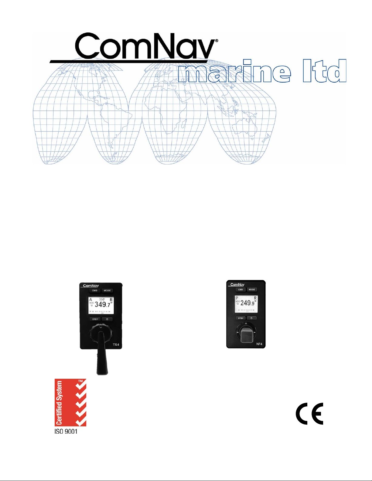
Installation & Operation Manual
P4 Remotes
for P4 Autopilot Systems
PN 29010102
COMPLIES WITH
CE REGULATIONS
TS4 Full Follow Up Remote NF4 Non-Follow up Joystick Remote
Page 2

Page 3

ComNav P4 Remotes Installation & Operation Welcome
Welcome
Congratulations on your purchase of ComNav Marine’s TS4/NF4 Remote for P Series
Autopilot Systems! At ComNav, we are proud of our prominence as a leader in the design
and manufacture of marine autopilot systems. Our dedication to performance and reliability
will ensure your satisfaction with the Remotes.
ComNav Marine Ltd.
Warranty Notice
The Warranty for the Remotes is contained within the Warranty of your P4 Autopilot System.
Prior to the installation and/or operation of the Remotes, ensure that you read, understand,
and accept the conditions of the P Series Autopilot System warranties as detailed in the
Warranty Information of that system,
Operator’s Warning
The P4 Autopilot System (with or without the Remotes) will steer your vessel. However, it is
only an aid to navigation. Its performance can be affected by many factors including
equipment failure, environmental conditions, and improper handling or use. An autopilot
system does not reduce your responsibility for the control of the vessel when underway. You
must always be in a position to monitor the course, supervise the autopilot, and resume
manual control if the need to do so arises.
Whenever underway, your vessel must be under the control of a qualified and alert person.
General Notice
This document, ComNav part number 29010102 Version 0 Revision 1, is the approved
Installation and Operation Manual for use with TS4/NF4 Remotes for P4 Autopilot Systems.
Where versions of this manual exist in other languages, the English version shall be
considered authoritative.
Document PN 29010102 V1r1 - 1 -
Page 4

ComNav P4 Remotes Installation & Operation Welcome
Revision
Date
Description
1R0
10 August, 2018
- first release
Document History
Document PN 29010102 V1r1 - 2 -
Page 5

ComNav Remote Installation & Operation Table of Contents
Table of Contents
Installation & Operation Manual ............................................................................................................... 1!
Welcome ..................................................................................................................................................... 1!
Document History ...................................................................................................................................... 2!
Table of Contents ....................................................................................................................................... 3!
List of Figures ............................................................................................................................................ 5!
List of Tables .............................................................................................................................................. 5!
Introduction ................................................................................................................................................ 7
Overview of the TS4 Remote .................................................................................................................... 9!
About this Manual .................................................................................................................................... 10!
Typefaces, Common Phrases & Terms ................................................................................................. 10!
Manual Format ....................................................................................................................................... 11!
Installation ................................................................................................................................................ 13!
Technical Requirements ......................................................................................................................... 15!
Caution Warning ................................................................................................................................. 15!
Electrical Connections ............................................................................................................................ 15
Network Connection in a P4 System ...................................................................................................... 15
Operation .................................................................................................................................................. 17!
User Interface ......................................................................................................................................... 19
Display Controls ..................................................................................................................................... 20!
BRIGHTNESS .................................................................................................................................... 20!
DAY & NIGHT MODE ......................................................................................................................... 20!
Normal Usage ........................................................................................................................................ 21
Taking Command ................................................................................................................................... 21
Modes of Operation ................................................................................................................................ 21!
STANDBY (STDBY) Mode ................................................................................................................. 22!
TILLER Mode ...................................................................................................................................... 22!
AUTO Mode ........................................................................................................................................ 22!
Change Course in NF4 ....................................................................................................................... 23!
Work Mode ......................................................................................................................................... 23!
Course Recall ..................................................................................................................................... 23!
NAV Mode .......................................................................................................................................... 23!
Alarm Clear ......................................................................................................................................... 23
Shortcut Functions in NFU ......................................................................................................................... 24
Operating Menu ......................................................................................................................................... 24
Off Mode or Sleep Mode ............................................................................................................................ 25
Document PN 29010102 V1r1 - 3 -
Page 6

ComNav Remote Installation & Operation Table of Contents
Appendices ............................................................................................................................................... 27
Multi SPU Installation .............................................................................................................................. 29
Care & Maintenance ................................................................................................................................. 29
Specifications ........................................................................................................................................... 29!
Index .......................................................................................................................................................... 31!
User Notes ................................................................................................................................................ 37!
Document PN 29010102 V1r1 - 4 -
Page 7

ComNav P4 Remotes Installation & Operation Tables & Figures
List of Figures
Figure 1 – P Series Autopilot System (partial diagram) ............................................................................. 9!
Figure 2 – Mode Buttons ........................................................................................................................... 21
Figure 3 – TS4 / NF4 LCD Screen .................................................................................................. 16,24,25
!
List of Tables
Document History......................................................................................................................................... 2
User Interface ............................................................................................................................................. 19
Current Mode ............................................................................................................................................. 22
Initial Mode ................................................................................................................................................. 24
Specifications ............................................................................................................................................. 29
User Notes ................................................................................................................................................. 35!
Document PN 29010102 V1r1 - 5 -
Page 8

ComNav P4 Remotes Installation & Operation
Document PN 29010102 V1r1 - 6 -
Page 9

ComNav P4 Remotes Installation & Operation
Introduction
Document PN 29010102 V1r1 - 7 -
Page 10

ComNav P4 Remotes Installation & Operation
Document PN 29010102 V1r1 - 8 -
Page 11
ComNav P4 Remotes Installation & Operation Introduction
NMEA2000 Termi nator
(Female), PN3181 0015
P4 SPU, PN20140001
P4 Control Head
TS4 Remote
NF4 Remote
NMEA 2000(N2K) C onnectio n - 6m drop cab le, Male & Female (P N31110052)
NMEA2000 Terminator
(Male), PN3181001 6
NMEA 200 0(N2K) Conn ection - Tr unk (Backb one) cable
12-24V
Battery
Block Diagram of the P4 System
12-24V
Battery
12-24V
Battery
N2K de vices
(Compass,
Plotter etc.,)
Connections for :
All Analog device s such as
Fluxgate
& Magnetic Compasses, Rotary Rudde r
Followe r, D rives & Moto rs.
All NMEA d evices su ch as Co mpasses & Navigat ion plotte rs
N2K
Pigtail t o Male C able,
1m,PN61110063
2m, Head Power Cable,
PN61110072
N2K
T-connector,
PN31810008
SiTexSP38
NMEA 200 0(N2K) Conn ection - 6 m cable , Pig tail & Male (P N3111 0073)
Overview of the TS4 Remote
The TS4 Remote is designed to work with ComNav’ s P4 Autopilot System.
The TS4 Remote allows the vessel operator to control the P4 Autopilot’s steering
functions from a workstation, flying bridge, on the side or stern decks, or any other
remote location on the vessel.
Features included in the TS4 Remote:
• Backlit graphical LCD display shows important system information, with easy selection
of display brightness and day-night display mode.
• Selection of’ STANDBY, AUTO, and NAV modes are done using the Mode button
(also supports WORK mode when in AUTO mode)
• Handheld operation, with built-in slots for “hang-up posts” on the back side
• Fully watertight case, made of high-impact material with excellent resistance to most
chemicals, a cable strain relief and button/switch & Tiller knob seals
• NMEA 2000 installation
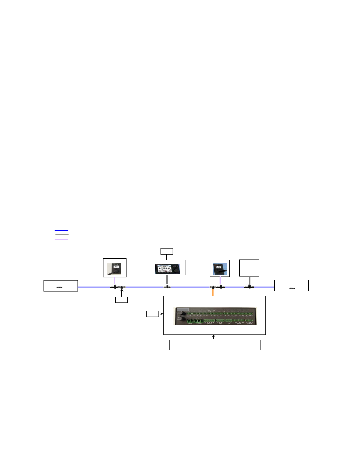
The block diagram below shows how the TS4 Remote is used in a P4 system:
Figure 1 – P Series Autopilot System (partial diagram)
Document PN 29010102 V1r1 - 9 -
Page 12

ComNav P4 Remotes Installation & Operation
About this Manual
This manual provides essential information for the safe and reliable operation of the ComNav
Remotes for P4 Autopilot Systems. You are urged to read this manual in its entirety before
you use your autopilot for the first time, and to keep it handy until you become thoroughly
familiar with the operation of your autopilot.
A number of steps in this manual require use of the setup menus and operational displays on
the Control Head of the P Series Autopilot System. Please refer to your P Series Installation
and Operation manual for instructions.
Typefaces, Common Phrases & Terms
Throughout this manual, you will see a number of different typefaces used, and several
commonly-used words & phrases with very specific meanings, to describe concepts & actions
that are fundamental to the operation of the autopilot. Please take a moment to become
familiar with the following items:
Modes of Operation
Specific “modes of operation” are placed in bold uppercase lettering.
Example: POWER STEER mode.
Button
TS4 Remote buttons and controls are placed in uppercase lettering.
Example: the MODE button.
System Component
Specific System Components are capitalized.
Example: The Control Head.
LCD Display
Text that appears in the LCD display is in quotation marks.
Example: “Waypoint Arrival”
press or momentary press
Press and release the indicated button.
double-press
Press and release the indicated button twice in rapid succession.
Although this sounds a little complicated, it is actually very easy to do – it is very similar to the
“double-click” action on a button of a Personal Computer Mouse.
press and hold
Press and hold the indicated button for a minimum of one-half of a second.
This time delay is purposely programmed into the system’s response to some buttons, to
prevent casual or accidental activation of the button function. For example, pressing the
MODE switch can, depending on system configuration, drastically alter the steering
performance of the P Series Autopilot System.
maintain
Hold the indicated button for as long as required to achieve a given result.
Example: To avoid obstacle, either take control manually or move the Joystick to the right or
left and hold to change course and maintain it in that position until the vessel has dodged
clear of the obstacle in its path.
Document PN 29010102 V1r1 - 10 -
Page 13

ComNav P4 Remotes Installation & Operation
Manual Format
This manual has been formatted to be printed on both sides of the pages of the manual, and
on standard Letter-sized paper (8.5” x 11”). If you have obtained this manual as a soft-copy,
please note that it is in Adobe® Portable Document Format (“pdf”), and so may be viewed &
printed with Adobe Reader®, or compatible pdf-format viewers.
When printing this manual with Reader, you should select “duplex printing” (or the equivalent
term used by your printer’s software driver), in order to print it double-sided on the paper. If
your printer does not have built-in duplexing capability, you can still print this manual doublesided by following the instructions that came with your printer for doing “hand duplexing”.
Document PN 29010102 V1r1 - 11 -
Page 14

ComNav P4 Remotes Installation & Operation
Document PN 29010102 V1r1 - 12 -
Page 15

ComNav P4 Remotes Installation & Operation
Installation
Document PN 29010102 V1r1 - 13 -
Page 16

ComNav P4 Remotes Installation & Operation
Document PN 29010102 V1r1 - 14 -
Page 17

ComNav P4 Remotes Installation & Operation
Installation
Technical Requirements
The following are the basic technical requirements that should be met before installation of
the TS4 Remote on your vessel.
For information regarding the installation of the complete P4 Autopilot
System, consult your P4 Installation & Operation Manual.
Caution Warning
Please refer to the Warranty Information document that accompanies your
P Series manual before proceeding with installation of the Remotes.
Extreme caution is advised when using tools powered by alternating
current (AC) from main AC supply circuits, regardless of whether the
supply circuits are “indoor”, “outdoor”, “marine” or “industrial” rated.
Water, especially sea water, is an EXCELLENT conductor of electricity,
and can complete a path to AC Ground through a person’s body,
causing injury or death, if a tool malfunctions or short-circuits.
Hazard warning!
CAUTION!
⇒ Battery powered tools are STRONGLY recommended
⇐
If AC tools are used, they MUST be plugged into a circuit that is
adequately protected against Ground Faults and other safety hazards,
in accordance with local electrical codes.
Electrical Connections
A P4 remote (TS4 or NF4) comes with a 6-meter cable with a male 5-pin micro NMEA 2000
connector. Each unit is also shipped with a T-connector. Insert the T connector to a
convenient location in your system, taking into the consideration to make a balanced
installation for the whole system.
Network Connection in a P4 system
An out-of-box P4 remote (TS4 or NF4) will automatically connect to a P4 SPU it first sees
after power up. If you have a P4SPU, and you have never made an installation change to the
P4 SPU from its factory default, once you power up your P4 remote, the P4 remote is ready
to take command and steer your boat as described in the Operation section.
P4 remote is an accessory. It can only be used to operate the autopilot when the autopilot
has started up and in normal operation modes. Normal operation modes for P4 SPU are
Standby mode, Auto mode, Power Steer mode and Nav mode.
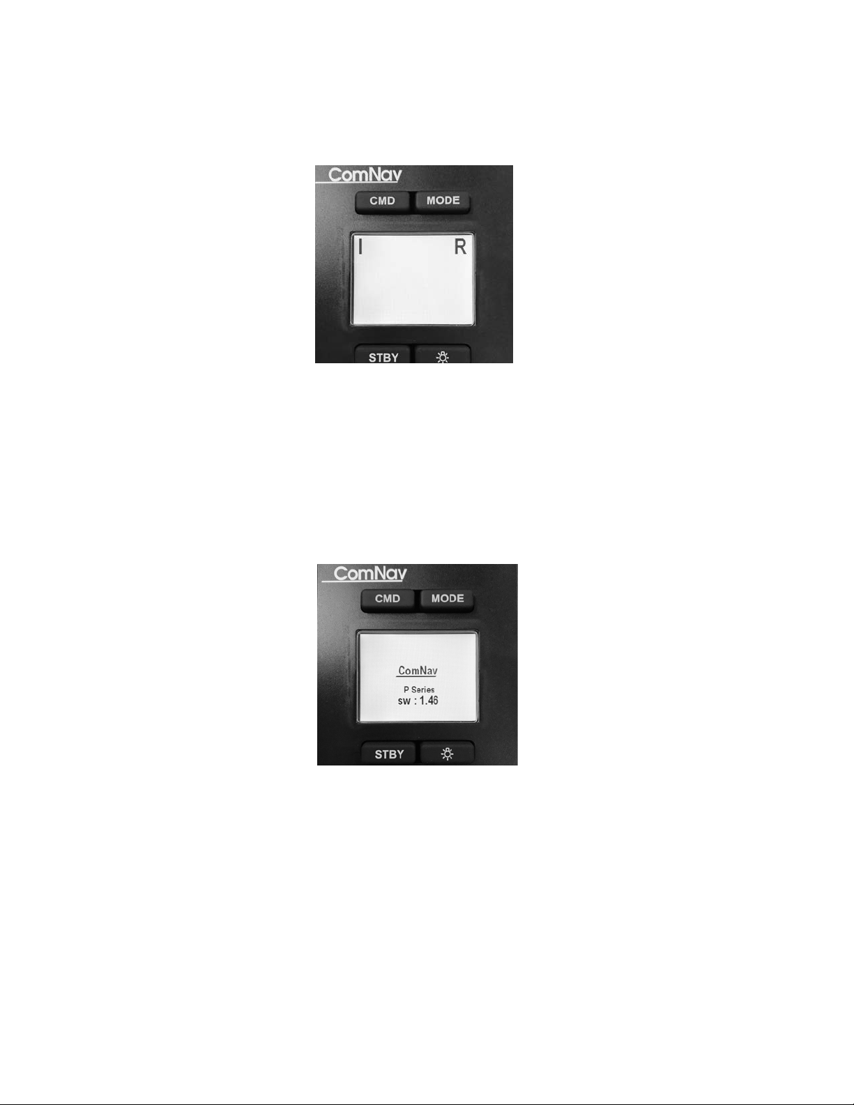
In normal operation mode, a P4 remote displays a screen like those in Figure 3.
Document PN 29010102 V1r1 - 15 -
Page 18
ComNav P4 Remotes Installation & Operation
If the SPU is not in a normal operation mode, a P4 remote will wait in start up mode, and
show a screen like below:
Figure 3 – TS4 / NF4 LCD Screen
After the first power up in a P4 system (with a P4 SPU present), your P4 remote however is
fixed to that particular SPU, and will not automatically change.
If for any reason you have changed the network installation of your P4 SPU, or you have
replaced a new P4 SPU, you must adjust your P4 remote to make another link again. You
know your P4 Remote is waiting for an SPU when after power up, it stays in the start-up
screen (figure below):
Figure 2 – TS4 / NF4 LCD Screen
Refer to Operating Menu in page 25 for how to link the P4 Remote to an SPU again.
Document PN 29010102 V1r1 - 16 -
Page 19

ComNav P4 Remotes Installation & Operation
Operation
Document PN 29010102 V1r1 - 17 -
Page 20

ComNav P4 Remotes Installation & Operation
Document PN 29010102 V1r1 - 18 -
Page 21

ComNav P4 Remotes Installation & Operation Operation
Button
Button Action
Operation mode
Condition
Function Result
CMD
Short Press
Normal operation
modes
REMOTE as a
repeater
Request to P4 SPU
for taking command
Double click
Start up mode and
Normal operation
modes
REMOTE as a
repeater
Initiate the
configuration menu
Click
Configuration menu
Root menu
Select current item for
editing
Click
Configuration menu
Editing a menu item
Save the item value
and go back to the
menu list
Click
Mode selection menu
REMOTE is in
command
Immediately request
a mode change
without waiting for
time out
MODE
Short press
Normal operation
modes
REMOTE is in
command
Initiate Mode
selection menu
Click
Mode selection menu
REMOTE is in
command
Move to the next
available mode
Click
Configuration menu
Root menu
Move to the previous
menu line
Click
Configuration menu
Editing a menu item
Increase the item
value
STBY
Short press
Normal operation
modes
REMOTE is in
command
Request to P4 SPU
for switching to
Standby mode
Click
Configuration menu
Root menu
Cancel / close the
menu
Click
Configuration menu
Editing a menu item
Cancel editing and go
back to the menu root
Click
Mode selection menu
REMOTE is in
command
Cancel the selected
mode (cancel the
timer) and stay in the
current mode
Lite (*)
Click
Normal operation
modes
No menu operation
Increase the LCD
brightness 1 step.
After maximum
brightness, it returns
to the lowest.
Long press
Normal operation
modes
No menu operation
Toggle between day
and night mode
Click
Configuration menu
Root menu
Move to the next
menu line
Click
Configuration menu
Editing a menu item
Decrease the value of
the menu item
User Interface
P4 Autopilot Remotes have 4 buttons and a tiller or Joystick as the user input interface. The table
below shows their functions in under different operation mode.
Document PN 29010102 V1r1 - 19 -
Note: Required that the Config Menu can ONLY be opened in repeater / remote state.
Page 22

ComNav P4 Remotes Installation & Operation Operation
Display Controls
You can make adjustments to the display brightness through the button.
BRIGHTNESS
This refers to the brightness of the LCD backlighting. There are 8 levels available; a level of
“1” is the minimum level of backlight, while 8 is the brightest.
Day/Night mode
The high brightness may be a safety hazard in night time. These Remotes have a night mode
for display where the information is displayed in Red and black. The minimum brightness is
also significantly lower than in day time.
Document PN 29010102 V1r1 - 20 -
Page 23
ComNav P4 Remotes Installation & Operation Operation
Normal Usage
Taking Command
In order to use the Remote, it is first necessary to “take command” away from the control
head unit in the system.
Check to see that the Station Lock setting on the Control Head is set to “Unlock”. Then press
and hold CMD button on the Remote until the letter “R” in the upper right of the display
disappears. The Control Head will now have a large letter “R” in the middle left portion of the
display, indicating that it is in “Repeater” mode.
Important! Always remember that the Remote is “in command” unless a
large letter “R” is shown in the upper right of the display.
To take command away from the TS4 Remote, go back to the Control Head (or another
Remote) and press the Command (CMD) button on the Head (or Remote). The “R” in the
middle left hand of the Control Head’s display will disappear and you will then have command
of the Autopilot at that Control Head (or Remote). An “R” will appear in the upper right of the
Remote display, which indicates that it is in “Repeater” mode.
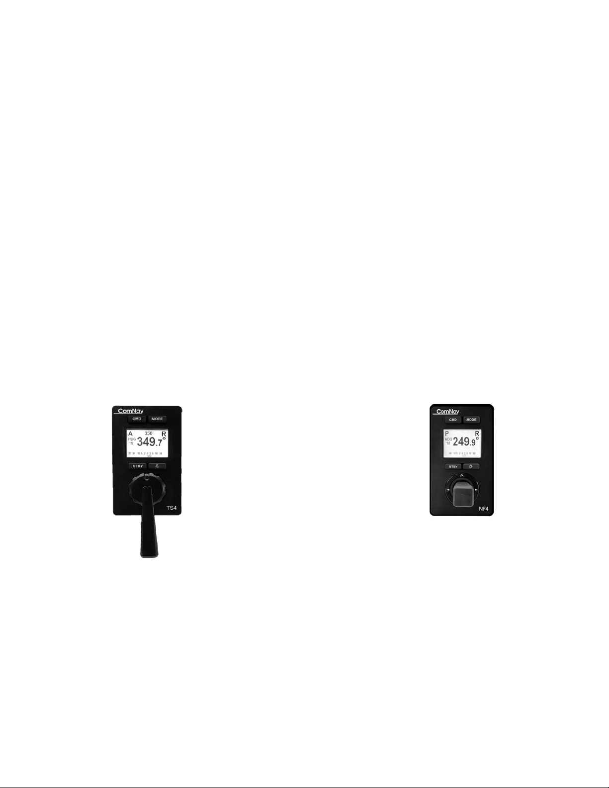
Modes of Operation
TS4 Full Follow Up Remote NF4 Non-Follow up Remote
Figure 3 – Mode Buttons
Document PN 29010102 V1r1 - 21 -
Page 24

ComNav P4 Remotes Installation & Operation Operation
Current mode
Available modes
Note
Standby
Power steer, Auto, Nav
Power Steer
Auto, [Auto-recall], Nav
Auto-recall only when recall course
is available
Auto
Work mode, Power steer, Nav
Auto – work mode
Auto, power steer, nav
Nav
Power steer, auto
STANDBY (STBY) Mode
If the Remote is In-Command, press STDB button to return to STANDBY Mode. No controls
on the Remote will have any effect on the vessel’s rudder.
Mode selection menu
If the Remote is In-command, press Mode button will bring up a list of all available modes
(except Standby mode). A mark is in front of the item to indicate it as the next pick.
Press Mode again when the mode list is on will move the mark to the next line.
Press CMD, Remote will initiate a mode change immediately.
Press STBY will cancel the selection and the list will disappear. No further action will be taken
The menu selection list will time out in about 2 seconds. After 2 seconds expiration, Remote
will request a mode change to SPU.
The following table shows the available mode list in different modes.
TILLER Mode
When your P4 remote is model TS4, the Power steer mode of P4 system becomes TILLER
mode. The autopilot will move the rudder to follow the position of TS4’S tiller.
Non- Follow Up Mode
When your P4 remote is model NF4, the power steer mode of P4 system
becomes a Jog switch. Moving the joystick to the right will move the rudder to
Starboard and moving the joystick to left will move the rudder to port side as
long as the joystick handle is held in the right or left position.
AUTO Mode
If the TS4 or NF4 Remote is In-Command and the Remote is in “AUTO” mode, the Autopilot
will lock on to the present course and maintain it. How to change the course depends on what
type of P4 remote you have.
Change'Course'in'TS4'
In Auto mode, the TILLER Lever is used to change the steering course. Move the tiller to
starboard and then move it back to the center will increase the course by 1 degree. Likewise
if you do that to port side you will decrease the course by 1 degree. If you hold the tiller on
starboard or port side without moving back, you will see course changes 1 degree for every
second in the first 10 seconds. If you hold the tiller longer than 10 second, the course will
change in a 10-degree increment.
Document PN 29010102 V1r1 - 22 -
Page 25

ComNav P4 Remotes Installation & Operation Operation
Change Course in NF4
When NF4 Remote is in command and in AUTO mode, moving the Joystick handle UP will
switch the mode to AUTO mode, while moving it DOWN will switch to STBY mode.
When NF4 is in AUTO mode and the Joystick is moved once to the right will initiate a 1degree course change to Starboard and if the Joystick is moved to the left-hand side, it will
initiate a 1-degree course change to Port side. When NF4 is in STBY mode, moving the
Joystick in Right or left direction switches the Remote into POWER STEER mode.
WORK Mode
While the Autopilot is in AUTO mode, you have the option to toggle between Work mode and
non-work mode. This is done through the mode select menu just like you change the
operation modes.
A letter “W” will appear in the upper left of the display to indicate that the system is now in
WORK mode (for most vessel types) Refer to the appropriate section in the P4 Installation &
Operation manual for details on these modes.
Course Recall
Some time when you are in Auto mode, you want to temporarily steer the vessel in manually.
In such situation, you can change the mode to (Power Steer) mode, and then switch back to
Auto mode. Select Course-recall mode from the mode list will allow you to go back to
autopilot’s last commanded course.
Note the last commanded course will only be available when you immediately go back to
Auto mode.
NAV Mode
If the TS4 or NF4 Remote is In-Command and is in “NAV” mode, the Autopilot will lock on to
the commanded course given by the NMEA Navigation device connected to the Autopilot.
For more information on NAV Mode, refer to the appropriate sections in the P Series
Installation & Operation manual.
The TILLER lever has no effect in NAV Mode.
Alarm Clear
Should an alarm condition occur within the P4, an audible alarm within the
Remote will sound. Press CMD button will suppress the alarm.
The audible alarm also sounds whenever a pushbutton is activated.
Document PN 29010102 V1r1 - 23 -
Page 26
ComNav P4 Remotes Installation & Operation Operation
Initial Mode
Resulting mode and associated functions from Joystick movement
Up
Down
Left/Right
Standby
Auto
No action
P.str NFU mode and move rudder
P.Str.
Auto
Center rudder
Move rudder in the direction
Auto
Set current
heading as
steering course
Standby
Change course
NAV
AUTO
Standby
No action
Shortcut functions in NF4
If you have an NF4, aside from using buttons to change operation mode, you have a quick access to
many functions by using the joystick. Table below shows a summary of these operations.
Operating Menu
P4 remotes are designed for easy connection and simple operation. However there are still
times you may need to make a few twists to your remote. This is done through the root menu.
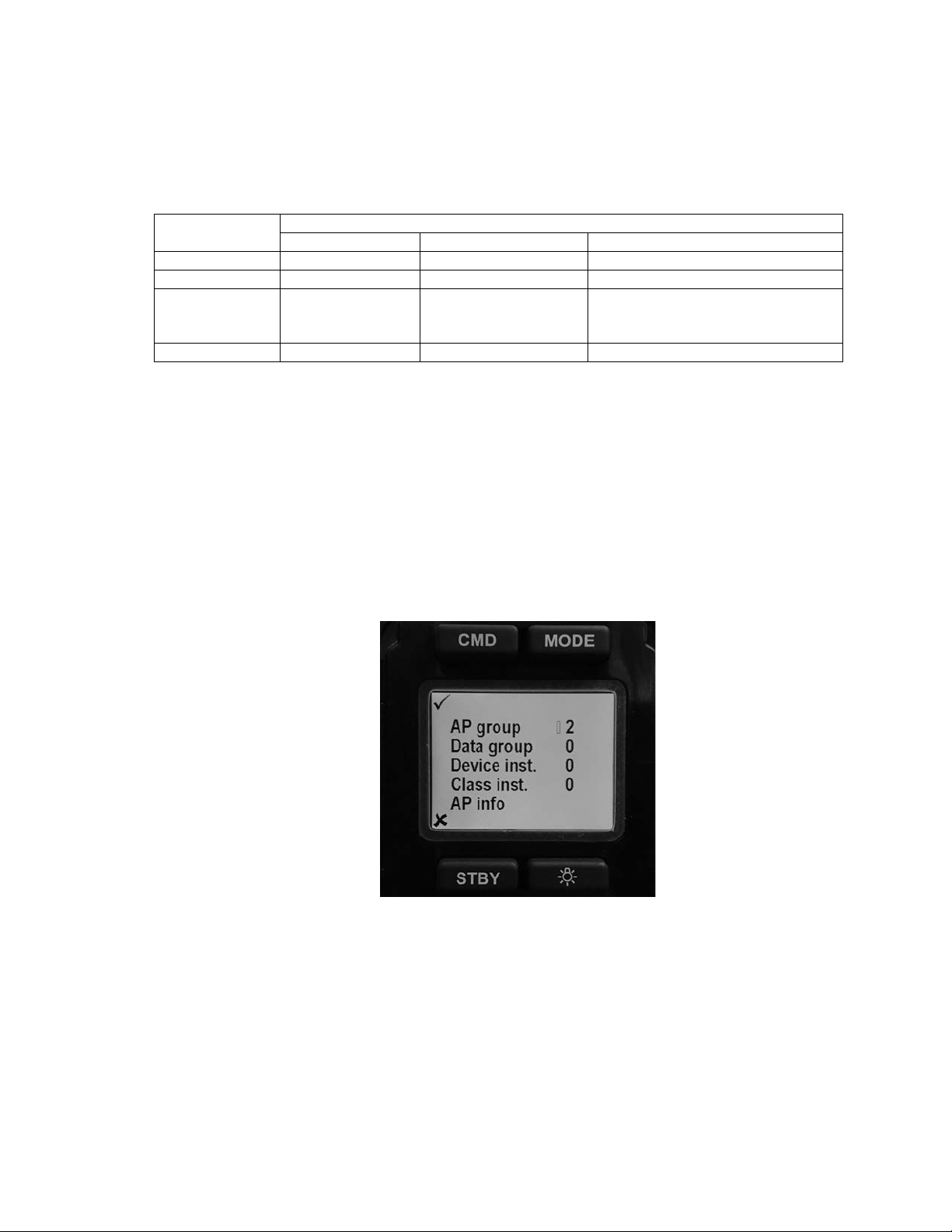
Double click on the CMD button will bring up the root menu as in Figure 3. Using Mode button
or Lite button to scroll up and down the list.
Press STBY will close the root menu if you have not selected an item. If you are editing an
item, press STBY will end the editing and ignore the change you have made and go back to
old values.
Press CMD selects the current item for editing. If you are editing an item, press CMD will
save the current value and end the editing.
Figure 3 – TS4 / NF4 LCD Screen
AP group
This value is used to identify different P4 systems in a network. If you have only one SPU, it
is recommended you don’t change the value
Data group
This value is future use
Document PN 29010102 V1r1 - 24 -
Page 27
ComNav P4 Remotes Installation & Operation Operation
Device inst.
This is the combined value of field 3 and field 4 of NMEA 2000 PGN 60928. If you make a
change to this value, it only takes effects at the next power cycle/on-off cycle.
Class inst.
This is the System instance value of PGN 60928. If you make a change to this value, it only
takes effect at the next power cycle/on-off cycle.
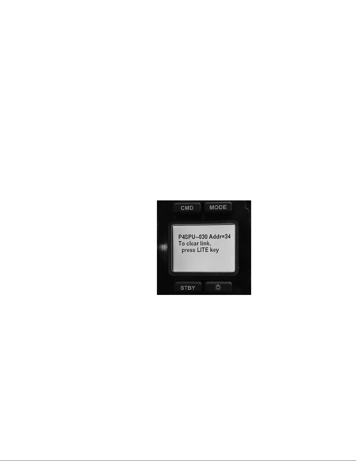
AP info
This item shows you the current P4 SPU you are linked to. In figure below the NMEA 2000
address of the SPU is 34. If the SPU is not online, you will see a blank address.
You can remove the linked SPU by press LITE button. The P4 remote will make a new scan
to the CAN bus to find a new SPU. If you have replaced your SPU, this is how you setup a
new link.
However, if you are to installed a second P4 system, and you want to connect the P4 remote
to a specific SPU, you must first POWER OFF the SPU you don’t want before you press LITE
to link the SPU you want.
Numbers behind P4SPU (“—030”) are the last 3 digits of the serial number of the P4 SPU.
.
Off mode or Sleep mode
P4 remote is powered by the NMEA 2000 bus it connects to. In order to synchronize with the
SPU and other control station in the network, P4 remotes do not have a power off state as
long as the network power presents.
However you can “turn off” a P4 remote locally if it is a repeater. In “turn off” state, the
backlight of P4 remote will be off. No display is seen, and the device will consume minimum
power.
Figure 3 – TS4 / NF4 LCD Screen
To turn off a P4 remote locally, press and hold the STBY button for over 3 seconds. A
message will be shown before the system goes to sleep.
To wake up a P4 remote locally, press and hold the STBY button until the screen lights up.
If the SPU the remote linked goes to sleep, the P4 remote will automatically go to sleep
mode. When the SPU wakes up, it will also wake up the P4 remotes.
Document PN 29010102 V1r1 - 25 -
Page 28

ComNav P4 Remotes Installation & Operation Operation
Document PN 29010102 V1r1 - 26 -
Page 29

ComNav P4 Remotes Installation & Operation
Appendices
Document PN 29010102 V1r1 - 27 -
Page 30

ComNav P4 Remotes Installation & Operation
Document PN 29010102 V1r1 - 28 -
Page 31

ComNav P4 Remotes Installation & Operation Appendices
Supply Voltage
12/24 VDC nominal
Supply Current
60 mA nominal 100mA maximum
Operating Temperature
-20°C to +70°C
Storage Temperature
-30°C to +85°C
Mounting
Keyhole Screw
Dimensions (maximum, without cable)
83mmx145mmx 38mm/3.2”x5.7”x1.4”
Weight w/cable /without cable
1.6lb/0.8 lb
Safe Distance to Compass
30cm/12inch
Multi-SPU installation
If there is more than one P4 system in your NMEA 2000 network, you need to specify which P4 system the
Remote is going to join.
Each component in a P4 system has a configuration setting AP group. This group number is an integral in
the range of 0 to 13. At factory default all P4 components have an AP group number 2.
Each SPU installed in the same network must be assigned a unique AP group value. Refer to P4
installation manual for how to set AP group for an SPU.
When a Remote joins a P4 system, it will automatically pick up a SPU with the same AP group number. To
move the Remote from one group to another, place the Remote in repeater mode, and double click CMD
button. Change the AP group number in the menu. After the group number has changed, the Remote will
automatically delete SPU information it has already pick up, and scan the network all over again.
Care & Maintenance
There are no user-serviceable parts or adjustments inside the Remote enclosure. Should the unit become
damaged in any way, return it to an authorized ComNav Dealer.
A few precautions will keep the unit in prime condition and result in years of trouble-free service:
• The Remote housing does not require any special maintenance other than an occasional cleaning.
• Avoid exposing the housing to solvents, acids, and bases as some of these may weaken the casing.
• Although the Remotes are watertight, it is not designed for submersion under water.
Specifications
Document PN 29010102 V1r1 - 29 -
Page 32

ComNav P4 Remotes Installation & Operation Appendices
Document PN 29010102 V1r1 - 30 -
Page 33

ComNav P4 Remotes Installation & Operation Appendices
Index
Document PN 29010102 V1r1 - 31 -
Page 34

ComNav P4 Remotes Installation & Operation Appendices
Document PN 29010102 V1r1 - 32 -
Page 35

ComNav P4 Remotes Installation & Operation Index
Index
Double-press ...................................................... 10
Installation .......................................................... 13
Maintain .............................................................. 10
Momentary press ................................................ 10
Power Supply ..................................................... 15
Press .................................................................. 10
Press and hold .................................................... 10
Technical Requirements ..................................... 15
Warranty ......................................................... 1, 15
Document PN 29010102 V1r1 - 33 -
Page 36

ComNav P4 Remotes Installation & Operation
Document PN 29010102 V1r1 - 34 -
Page 37

ComNav P4 Remotes Installation & Operation
User Notes
Document PN 29010102 V1r1 - 35 -
Page 38

ComNav P4 Remotes Installation & Operation User Notes
Document PN 29010102 V1r1 - 36 -
Page 39

ComNav P4 Remotes Installation & Operation User Notes
User Notes
Document PN 29010102 V1r1 - 37 -
Page 40

ComNav P4 Remotes Installation & Operation User Notes
Document PN 29010102 V1r1 - 38 -
 Loading...