

Page 1
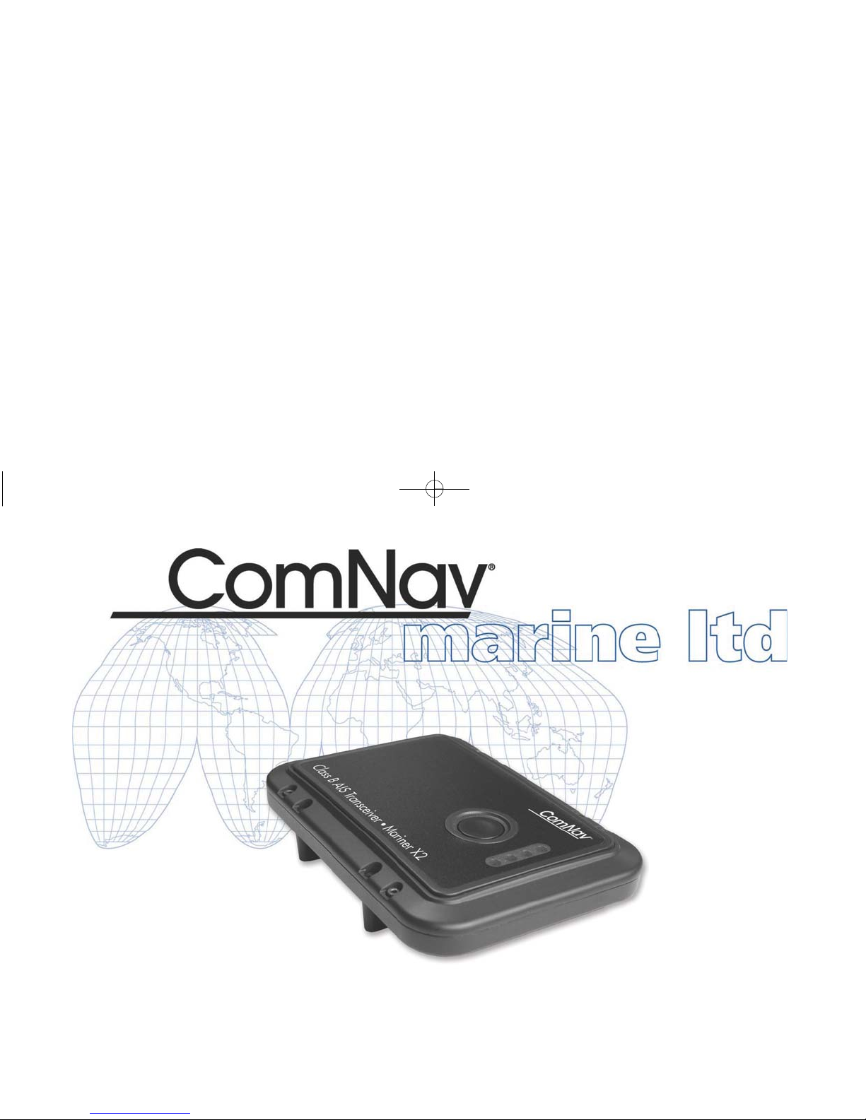
Class B AIS Transceiver • Mariner X2
Automatic Identification System
INSTALLATION MANUAL
Version 1.4
ComNavAISManual:COMNAV 9/28/2009 12:11 PM Page 1
Page 2

Thank you for buying this AIS Class B transceiver.
This product has been engineered to offer you the highest level of
performance and dura bi lity an d w e ho pe th at it w i ll pr ovi de many years of
reliable service. We constantly strive to achieve the highest possible
quality standards, should you encounter any problems with this product,
please contact your dealer who will be pleased to offer whatever
assistance you require.
WARNING
The Equipment is an aid to navigation only. It is not intended or designed to replace the person on watch. A qualified person should
always be in a position to monitor the vessel’s heading, and to watch for navigational hazards, and should be prepared to revert to
manual steering im mediately i f an unde sired change of headi ng occurs, if th e heading i s not maint ain ed within reas onable li mits , or w hen
navigating in a hazardous situation.
ALWAYS REMEMBER:
WHENEVER UNDER WAY, A QUALIFIED PERSON ON WATCH IS REQUIRED BY LAW.
Page 3

1 Notices ..................................................................................................1
1.1 Safety warnings................... .............................................. .....................1
1.2 General notices............................................ .... .. ......... .. .... .... .. ......... .... .. 1
2 About your AIS class B transceiver ............................................... .. ..3
2.1 About AIS................. .. ....... .. .. .. .... .. .. ....... .. .. .... .. .. .. ....... .. .... .. .. .. ....... .. .. ....3
2.2 Static and dynamic vessel data..............................................................3
2.3 Important information for US customers.................................................4
2.4 What's in the box?..................................................................................5
3 Installation............................................................................................7
3.1 Preparing for Installation ........................................................................7
3.2 Installation procedures...........................................................................9
4 Configuring your Mariner X2.............................................................15
4.1 Switch in g o n you r Mar i n e r X2 for the first time.....................................15
4.2 Introduction to the proAIS software......................................................16
4.3 Inst a llin g th e p roA IS software.................................... ...........................16
4.4 Conf ig u ration using proAIS..................................................................17
5 Operation ............................................................................................19
5.1 Using the Mariner X2............................................................................19
5.2 Switch fu n ctions ...................................................................................19
5.3 Using proAIS with your Mariner X2......................................................20
5.4 Indicator functions................................................................................23
6 Troubleshooting.................................................................................24
7 Specifications.....................................................................................25
Figure 1 Items included in the product................................................... .. 5
Figure 2 Mariner X2 overview.................................................................. 6
Figure 3 Electrical connections to the Mariner X2 ................................... 6
Figure 4 Typical installation configuration................................................7
Figure 5 Mariner X2 dimensions............................................................10
Figure 6 Mariner X2 mounting............................................................... 10
Figure 7 GPS antenna mounting ...........................................................11
Figure 8 Position of the GPS antenna connector ..................................11
Figure 9 Position of the VHF antenna connector...................................12
Figure 10 Connecting an external switch.................................................12
Figure 11 Connecting to the NMEA0183 data port.................................. 13
Figure 12 Connecting the power supply..................................................14
Figure 13 Indicator start up sequence............................. ........................15
Figure 14 Enteri n g sta tic data into proAIS............................................... 16
Figure 15 proAIS GPS status page........ ....................... ....................... ... 20
Figure 16 proAIS Di a g n o stics page...................... ........................ ........... 21
Figure 17 proAIS Othe r vessels page................................................. ..... 21
Figure 18 proAIS Messages page ...........................................................22
Figure 19 proAIS Se rial data page ..........................................................22
Figure 20 Indicator location on the Mariner X2 unit................................. 23
Table of contents Table of figures
Page 4
Notices
Page 1
1Notices
1.1 Safety warnings
1.2 General notices
Position source
All marine Automatic Identification System (AIS) transceivers utilise
a satellite based location system such as the Global Positioning
Satellite (GPS) network.
The accuracy of a GPS position fix is variable and is affected by
factors such as the antenna positioning, how many satellites are
used to determine a position and how long satellite information has
been received for.
Compass safe distance
The compass safe distance of this unit is 0.5m or greater for 0.3°
deviation.
RF emissions notice
Caution: The Mariner X2 generates and radiates radio frequency
electromagnetic energy. This equipment must be installed and
operated according to the instructions contained in this manual.
Failure to d o so can result in per sonal injury and / or M ariner X2
malfunction.
Caution: Never operate the Mariner X2 unless it is connected to a
VHF antenna.
To maximise performance and minimise human exposure to radio
frequency electromagnetic energy you must make sure that the
antenna is mounted at least 1.5 meters away from the Mariner X2
and is connected to the Mariner X2 before power is applied. The
system has a Maximum Permissible Exposure (MPE) radius of
1.5m. This has been determined assuming the maximum power of
the Mariner X2 and using antennas with a maximum gain of
3dBi.The antenna should be mounted 3.5m above the deck in order
to meet RF exposure requirements. Higher gain antennas will
require a greater MPE radius.Do not operate the unit when anyone
is within the MPE radius of the antenna (unless they are shielded
from the antenna field by a grounded metallic barrier).
The antenna should not be co-located or operated in conjunction
with any other transmitting antenna.
The required antenna impedance is 50 Ohms.
!
When reading this manual please pay attention to
warnings marked with the warning triangle shown on
the left. These are important messages for safety,
installation and usage of the product.
!
This equipment must be installed in accordance with
the instructions provided in this manual.
!
This equi pmen t is int end ed as an ai d to n avi gat io n and
is not a replacement for proper navigatio nal judgem ent.
!
Do not install this equipment in a flammable
atmosphere such as in an engine room or near to fuel
tanks.
Page 5
Notices
Page 2
Warranty
This product is supplied with standard warranty as defined in
section
8.
Disposal of this product and packaging
Please dispose of the Mariner X2 in accordance with the European
WEEE Directive or with the applicable local regulations for disposal
of electrical equipment.
Every effort h as be en made to ensure the packagi ng fo r th is pro du ct
is recyclable. Please dispose of the packaging in an
environmentally friendly manner.
Accuracy of this manual
The Mariner X2 may be upgraded from time to time and future
versions of the Mariner X2 may therefore not correspond exactly
with this manual. Information contained in this manual is liable to
change without notice. The manufacturer of this product disclaims
any liability for consequences arising from omissions or
inaccuracies in this manual and any other documentation provided
with this product.
Declaration of conformity
The manufacturer of this product declares that this product is in
compliance with the essential requirements and other provisions of
the R&TTE directive 1995/5/EC.
The product carries the CE mark, notified body number and alert
symbol as required by the R&TTE directive.
The product is intended for sale in the following member states:
Great Britain, France, Spain, Sweden, Austria, Netherlands,
Portugal, Denmark, Norway, Belgium, Italy, Finland, Ireland,
Luxembourg, Germany, Czech Republic.
FCC notice
This equipment has been tested and found to comply with the limits
for a class B digital device, pursuant to part 15 of the FCC Rul es.
These limits are designed to provide reasonable protection against
harmful interferenc e in a reside ntial installation.
This equipment generates, uses and can radiate radio frequency
energy and, if not installed and used in accordance with the
instructions, may cause harmful interference to radio
communications.
Industry Canada notice
This AIS class B digital apparatus complies with Canadian ICES-
003.
Cet appareil numérique de la AIS classe B est conforme à la norme
NMB-003 du Canada.
!
Any attempt to tamper with or damage this product will
invalidate the warranty.
!
WARNING: It is a violation of the rules of the Federal
Communications Commission to input an MMSI that
has not been properly assigned to the end user, or to
otherwise input any inaccurate data in this device.
Page 6

About your AIS class B transceiver
Page 3
2 About your AIS class B
transceiver
2.1 About AIS
The marine Automatic Identification System (AIS) is a location and
vessel information rep orti ng sy s tem . It all ow s ves se ls eq ui ppe d w ith
AIS to automatically and dynamically share and regularly update
their position, speed, course and other information such as vessel
identity with simi larly equipped vessels. Position is de riv ed f r om the
Global Positioning System (GPS) and communication between
vessels is by Very High Frequency (VHF) digital transmissions.
There are a number of types of AIS device as follows:
• C
lass A transceivers. These are similar to class B transceiver,
but are designed to be fi tted to larg e ve ss el s such as cargo ships
and large passenger vessels. Class A transceivers transmit at a
higher VHF signal power than class B transceivers and therefore
can be received by more distant vessels, and also transmits
more frequently. Class A transceivers are mandatory on all
vessels over 300 gross tonnes on international voyages and
certain types of passenger vessels under the SOLAS mandate.
• C
lass B transceivers. Similar to class A transceivers in many
ways, but are normally lower cost due to the less stringent
performance requirements. Class B transceivers transmit at a
lower power and at a lower reporting rate than class A
transceivers.
• AIS bas
estations. AIS basestatio ns are used by Vessel Traffic
Systems to monitor and control the transmissions of AIS
transceivers.
• Aids
to Navigation (AtoN) transceivers. AtoNs are
transceivers mounted on buoys or other hazards to shipping
which transmit det ails of thei r location to the surrounding ve ssels.
• A
IS receivers. AIS receivers will generally receive
transmissions from class A transceivers, class B transceivers,
AtoNs and AIS basestations but do not transmit any information
about the vessel on which they are installed.
2.2 Static and dynamic vessel data
There are two categories of information transmitted by an
AIS transceiver
: static and dynamic data.
The vessel's dynamic data, which includes location, speed over
g
round (SOG) and course over ground (COG), is calculated
automatically using the internal GPS receiver.
Static data is information about the vessel which must be
p
rogrammed into the Mariner X2. This includes:
• Maritime Mobile Service Identity (MMSI)
• Vessel name
• Vessel call sign (if available)
• Vessel type
• Vessel dimensions
In most countries the operation of an AIS transceiver is included
u
nder the vessel's marine VHF licence provisions. The vessel on to
Page 7
About your AIS class B transceiver
Page 4
which the AIS unit is to be installed must therefore possess a
current VHF radiotelephone licence which lists the AIS system,
vessel Call Sign and MMSI number.
2.3 Important information for US
customers
There are specific laws in the USA regarding the configuratio n of
AIS class B transceivers.
If you are a US resident and intend to use your AIS class B
transceiver in US waters, you should make sure that your retailer
has configured your product prior to supplying it to you. If your
Mariner X2 has not been pre-configured please contact your dealer
for details of how to have it configured.
!
An MMSI number is required in order for the Mariner X2
to operate. Please contact the relevant authority in
your country for more information.
!
In the United States of America, the MMSI and static
data must only be entered by a competent installer.
The end user of the equipment is not authorised to
enter their own static data.
Page 8
About your AIS class B transceiver
Page 5
2.4 What's in the box?
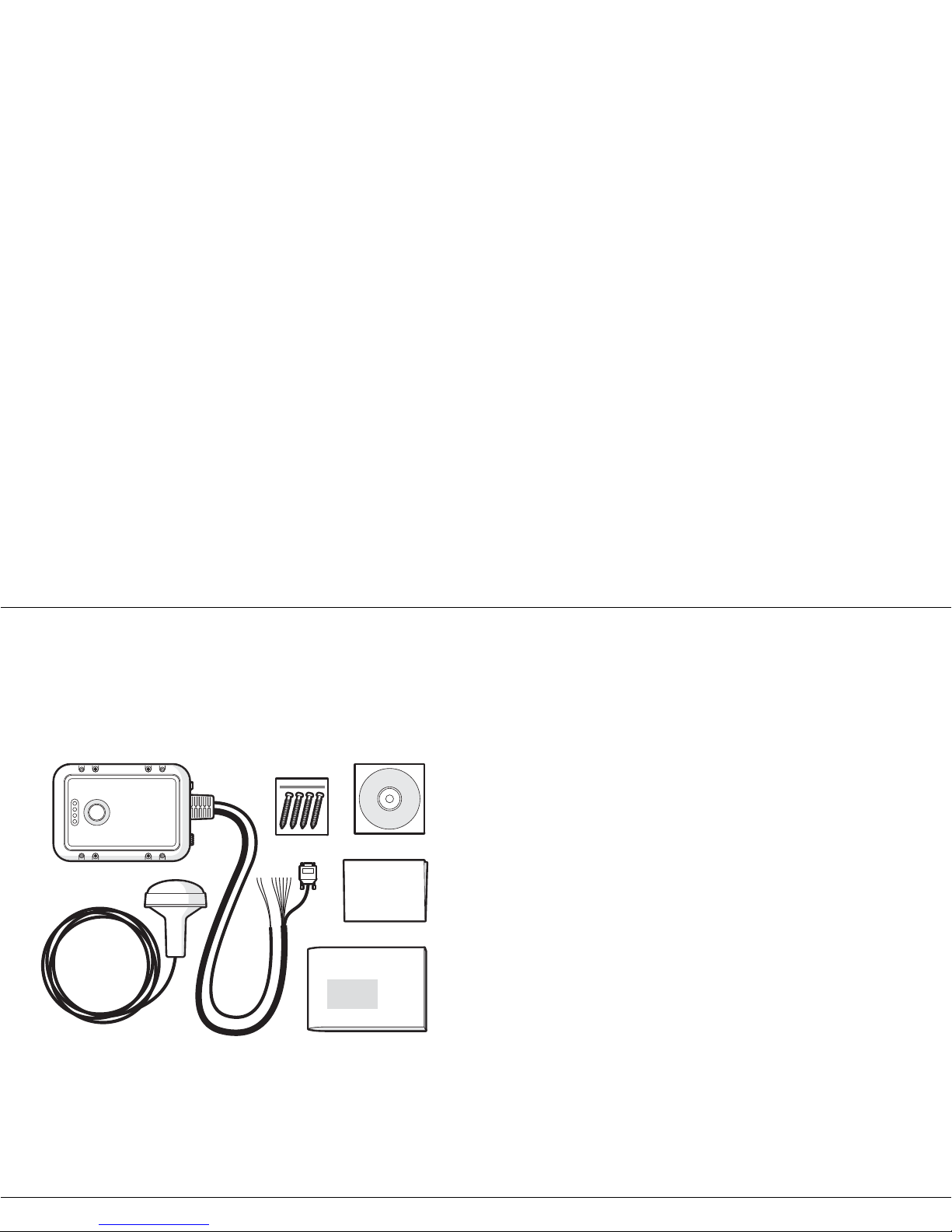
Figure 1 shows the items included with your Mariner X2 purchase.
The following sections give a brief overview of each item. Please
e
nsure all items are present and if any of the items are not present
contact your dealer.
Figure 1 Items included in the product
• Support tools CD
The CD supplied wit h the p ack age con t ains the proAIS sof tware t ool
n
ecessary to configure the Ma riner X2. Please refer to section 4 for
details of the config uration pro cess and how t o use the pr oAIS to ol.
• Quick start guide
The quick start guide gives a handy one page reference for the
i
nstallation proc ess.
• Product manual
This document is the produc t man ual an d sho uld be read t horo ughly
p
rior to any attempt to install or use the Mariner X2.
• GPS antenna
The GPS antenna forms an integral part of the product's internal
p
ositioning system based on GPS. Please refer to section 3.2 for
details of how to install the GPS antenna.
•Fixing screws
Four fixing screws are provided with the product for mounting of the
M
ariner X2. Please refer to section 3.2 for d etails of how to m ount
the Mariner X2.
• Mariner X2 unit
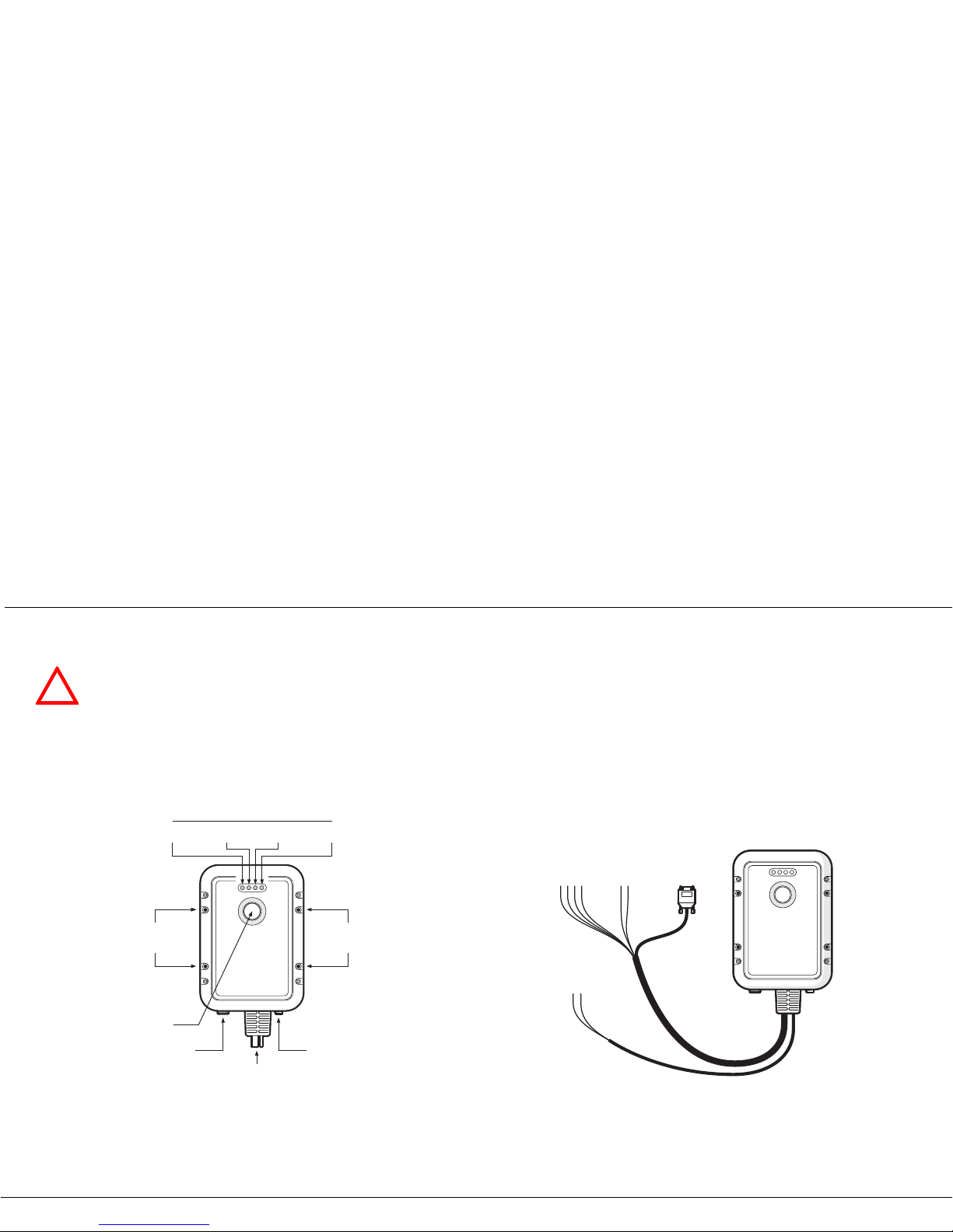
Figure 2 shows an overview of the Mariner X2 unit.
The Mariner X2 has a number of indicators which provide
i
nformation to the user about the status of the Mariner X2. Please
refer to section 5.4 for more details of indicator functions.
The Mariner X2 has a single switch which can be configured to
p
rovide certain functions as defined in section 5.2.
Screws
(packet of 4)
Product CD
Quick
start guide
Product manual
GPS Antenna
Class B AIS transceiver
Page 9
About your AIS class B transceiver
Page 6
Figure 2 shows the Mariner X2 mounting holes. Please refer to
section 3.2 for details of how to mount the Mariner X2.
Figure 2 Mariner X2 overview
Electrical connections
The Mariner X2 has the following connections provided by the
attached cables:
• Power supply
• NMEA0183 data port for connection to chart plotters
• RS232 for connection to a PC
• External switch input
In addition there are two other connections for the GPS antenna
and the VHF antenna.
Figure 3 Electrical connections to the Mariner X2
!
Do not attempt to adjust or remove the fixings next to
each of the four mounting holes. These fixings form
part of the sealing of the Mariner X2 and any
modification could affect the product's performance
and will invalidate the product's warranty.
Indicator lights
Switch
Mounting
holes
Mounting
holes
Blue Red Amber Green
Power and data cables
VHF antenna connector GPS antenna connector
Plotter
Power in
Switch RS232
Class B AIS transceiver
Page 10
Installation
Page 7
3Installation
3.1 Preparing for Installation
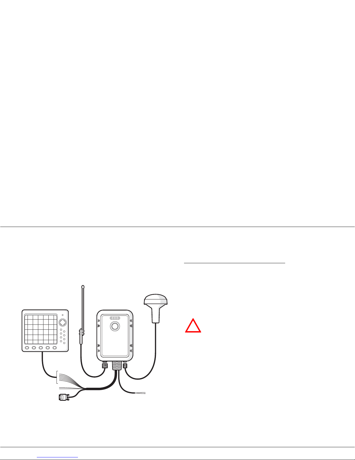
Figure 4 shows a typical installation configuration for the Mariner
X2. Please take the time to familiarise yourself with the system
e
lements and their connections prior to attempting installation.
Figure 4 Typical installation configuration
In addition to the items provided with your Mariner X2 the following
items will be required for installation:
VHF antenna
Connection to a suitable VHF antenna will be required for the
Mariner X2 to operate. A standard marine band VHF antenna such
as that used with VHF voice radios will be sufficient. Please take
note of the warnings in section 1 regarding the use of antennas.
Alternatively, if you wish to use an existing VHF antenna, antenna
splitter products are available which allow the existing antenna to be
used with two radio devices, such as a VHF voice radio and the
Mariner X2.
Antenna cables
The GPS antenna is provided with 10 metres of cable. If this is not
sufficient to reach between the desired GPS antenna location and
the Mariner X2 unit you will need an extension cable. Please
contact your dealer for details. For reference the GPS antenna
connector type on the Mariner X2 unit is TNC receptacle, and is
intended to mate with a TNC jack connector.
Switch
Power in
RS232
GPS Antenna
Class B AIS transceiverChartplotter
VHF Antenna
!
When selecting an AIS antenna splitter make sure it is
capable of operation with an AIS transceiver. Some AIS
antenna splitters are designed to work only with AIS
receivers. Please check with your dealer to ensure you
purchase the correct type of antenna splitter.
Page 11

Installation
Page 8
Please check that the VHF antenna you intend to use has sufficient
cable to reach betwe en the VHF antenn a and t he Mari ner X2 u nit. If
it is not sufficient you will need an extension cable. Please contact
your dealer for details of suitable products. For reference the VHF
antenna connector type on the Mariner X2 unit is SO 239, and is
intended to mate with a PL 259 connector.
Power and data cables
The Mariner X2 unit is supplied with a one metre long power and
data cable as an integral part of the Mariner X2 unit. If you require
longer cables to reach your power supply, please ensure the cables
are capable of carrying currents of up to 2A peak and 500mA on
average. Means of connecting the cables together will also be
required. The use of ScotchlokTM connectors is recommended for
this purpose.
Chart plotter
To display received AIS messages as other vessels on your chart
plotter, you will need to connect your Mariner X2 to your chart
plotter. Please refer to the user manual supplied with your chart
plotter for details of how to connect and configure your chart plotter
for use with AIS devices. For general guidance your chart plotter
should be configured to accept NMEA data at 38400 baud
(sometimes referred to as 'NMEA HS' in the plotter configuration
menu). You may also need to enable the display of AIS targets in
the chart options.
Connection to a PC
If you choose to use a PC with suitable charting software to display
received AIS messages as other vessels, this can be accomplished
by connecting the RS232 directly to the PC, or via a suitable RS232
to USB converter if your PC does not have a RS232 port.
GPS antenna mount
A one inch 14 TPI pole mount is required to mount the supplied
GPS antenna. Please contact your dealer for details of suitable
products.
Page 12

Installation
Page 9
3.2 Installation procedures
Before beginning installation of your Mariner X2, please ensure you
have the necessary additional items as detailed in section 3.1. It is
strongly recommended that you read all of the instructions in this
m
anual prior to installation.
If after reading t his m anu al you are unsure about any element of the
i
nstallation process please contact your dealer for advice.
The following sections explain the installation process step by step
fo
r each of the main elements of the system.
Step 1 - Installing the Mariner X2
Please note the following guidelines when selecting a location for
your Mariner X2:
• The Mari ner X2 must be fitt ed in a location w here it is at least
0.5
m from a compass or any magnetic device.
• There should be adequate space around the Mariner X2 for
rout
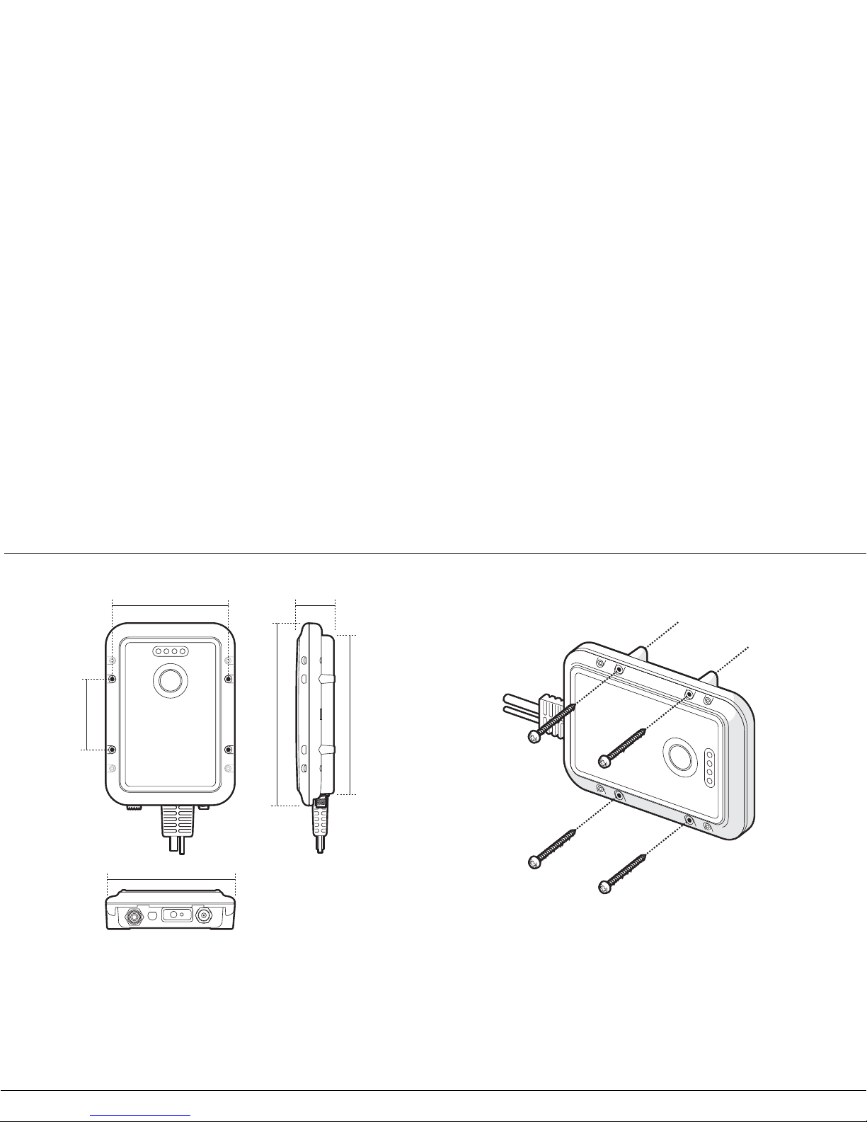
ing of cables. See Figure 5 for details of the Mariner X2
dimensions.
• The ambient temperature around the Mariner X2 should be
ma
intained between -10°C and +55°C.
• The Mariner X2 should not be located in a flammable or
haz
ardous atmosphere such as in an engine room or near to fuel
tanks.
• The Mariner X2 is fully waterproof to ingress protection rating
IPx7, however it is recommended that the Mariner X2 is not
subjected to extended periods of exposure to spray or
submersion.
• It is recommended that the Mariner X2 is installed in a 'below
de
cks' environment.
• It is acceptable to mount the Mariner X2 either vertically or
ho
rizontally.
• The product is supplied with four self tapping screws for
a
ttachment of t he M arine r X2 to a sui table su rfac e. P le ase re fer
to Figure 6 for guidance.
• The Mariner X2 should be mounted in a location where the
in
dicators are readily visible as these provide important
information on the status of the Mariner X2.
Page 13
Installation
Page 10
Figure 5 Mariner X2 dimensions
Figure 6 Mariner X2 mounting
215 mm
84 mm
185 mm
150 mm
137 mm
45 mm
Page 14
Installation
Page 11
Step 2 - Installing the GPS antenna
For mounting of the GPS antenna provided with your Mariner X2
you will require a one inch 14 TPI thread pole.
You should ensure the GPS antenna has a good clear view of the
entire sky.
It is not recommended that the GPS antenna is mounted up a mast
w
here the the motion of the vessel will cause the antenna to swing
and potentially reduce the accuracy of the GPS position.
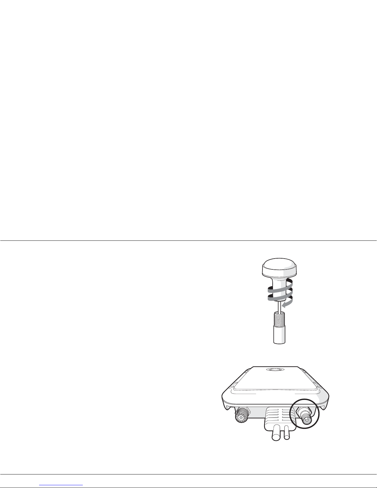
Do not mount your ant enn a i n the direct path of a radar transmi tter.
Feed the ten metre long cable attached to the GPS antenna cable
th
rough the pole and screw the antenna onto the pole mount as
shown in Figure 7.
Route the cable to your Mariner X2 unit, adding any necessary
ex
tension c ables.
Connect the cable from the GPS antenna to the GPS connector on
t
he Mariner X2 as shown in Figure 8.
Figure 7 GPS antenna mounting
Figure 8 Position of the GPS antenna connector
GPS Antenna
VHF Antenna
Page 15
Installation
Page 12
Step 3 - Connecting the VHF antenna
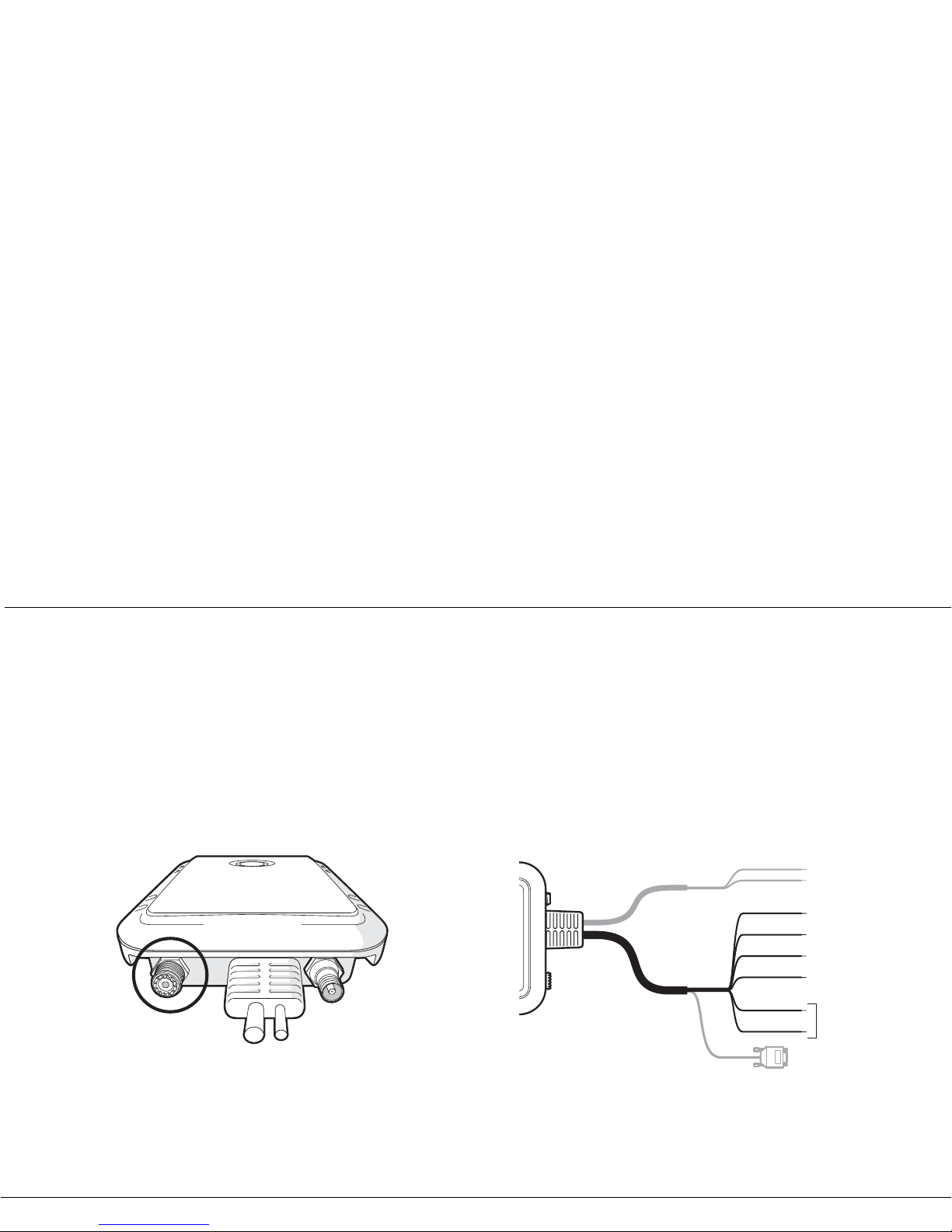
Route the cable from the VHF antenna to the Mariner X2 and
connect to the VHF connector on the M ariner X2 as shown in Figure
9.
A standard marine band VHF antenna or AIS antenna should be
us
ed with the Mariner X2. The connector type on the Mariner X2 is
SO239. Your chosen VHF antenna requires a PL259 connector to
mate with this. If your VHF antenna does not use this type of
connector please contact your dealer for details of available
adaptors.
Figure 9 Position of the VHF antenna connector
Step 4 - Connecting an external switch
If you require a remote external switch to activate the silent mode
feature, it is possible to connect a toggle switch to the Mariner X2
and configure the switch functi on ac cor din gly.
Connect the toggle switch between the orange and blue wires as
s
hown in Figure 10 and configure the switch function in proAIS to
'Make switch to disable transmitter'. For more details on how to do
this please refer to section 4.4.
Connection of an external switch to toggle silent mode is optional
an
d not essential for normal operation of the product.
Figure 10 Connecting an external switch
GPS Antenna
VHF Antenna
Yellow
Brown
White
Green
Transmit +
Transmit –
Receive +
Receive –
External switch
connection
Blue
Orange
Page 16
Installation
Page 13
Step 5 - Connecting to a chart plotter
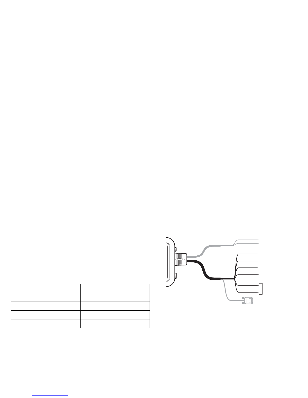
The NMEA0183 data port provides the connection to your chart
plotter and consist s of fou r wires col our coded as shown in the table
below and in
Figure 11. Connect the wires to the appropriate
connections on your chart plotter. Please refer to your chart plotter
manual for more information.
The NMEA0183 data po rt ope rates at a baud rate of 38400. Please
ensure your chart plotter is configured to receive data from the
Mariner X2 via its NMEA0183 port at 38400 baud.
Please note that the 'Receive' connections may not be needed
when connecting to your chart plotter as it is not normal for the
transceiver to receive data from the chart plotter
.
Connecting an optional NMEA0183 device
If you wish to connect a NMEA0183 device (such as a heading
sensor) to your chart plotter, but your chart plotter only has a single
NMEA0183 input, it is possible to use the Mariner X2’s NMEA0183
multplexing feature to connect both devices to the chart plotter.
To mult ipl ex yo ur NM E A01 8 3 dev ic e d a ta vi a th e M ar ine r X2 s im pl y
connect the device ’ s NMEA018 3 outp ut to the recei ve+ an d receive terminals as defined in the table above. Follow the instructions in
section
4.4 to configure the Mariner X2 to multiplex the devices
NMEA0183 data to your chart plotter.
Figure 11 Connecting to the NMEA0183 data port
Connection to a PC
The Mariner X2 is supplied with an RS232 port for connection to a
PC. The RS232 connector can be connected directly to the RS232
port on the P C or via a serial to USB con verte r if no RS 232 port is
available. For configuration of the Mariner X2 it is necessary to
connect to a PC if your Mariner X2 has not been pre-configured by
your dealer. See section
4 for more details of configuration.
NMEA0183 f unction Wire colour
Transmit + Yellow
Transmit - Brown
Receive + White
Receive - Green
Yellow
Brown
White
Green
Transmit +
Transmit –
Receive +
Receive –
External switch
connection
Blue
Orange
Page 17
Installation
Page 14
Step 6 - Connecting to a power supply
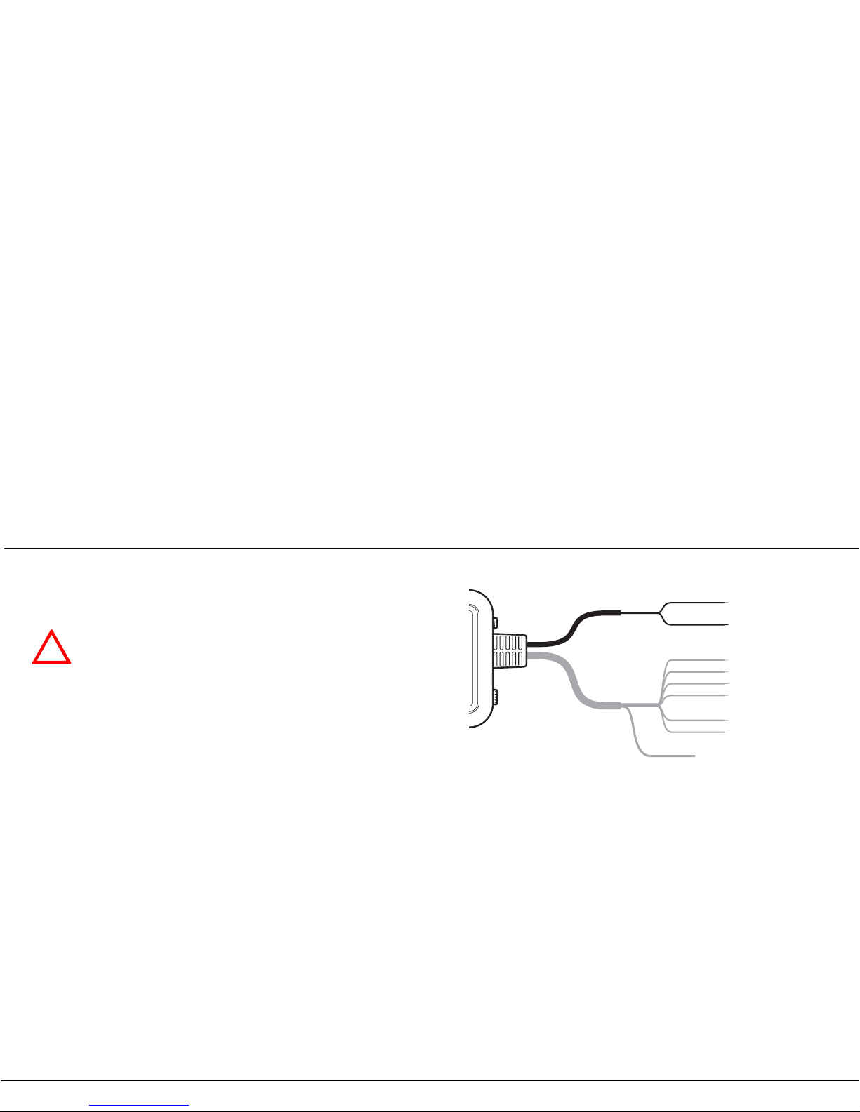
The Mariner X2 requires a 12V power supply typically provided by
the vessel's battery.
It is recommended that crimped and soldered lugs are used to
c
onnect the Mariner X2 to the power source.
It is recommended that th e pow e r su pply is connected via a suitable
c
ircuit breaker and/or 3A fuse block.
1. Connect the red wire to a 12V power supply positive terminal.
2. Connect the black wire to the supply negative terminal.
Figure 12 Connecting the power supp ly
!
Do not use a 24V power supply with the Mariner X2.
Should a 24V supply be connected to the Mariner X2,
an internal protection system will be invoked and the
Mariner X2 will not operate as normal. However, no
permanent damage will be caused to the Mariner X2.
The Mariner X2 will operate as normal once connected
to a 12V power supply.
Red
Black
Power supply +
Power supply –
Page 18
Configuring your Mariner X2
Page 15
4 Configuring your Mariner
X2
4.1 Switching on your Mariner X2 for
the first time
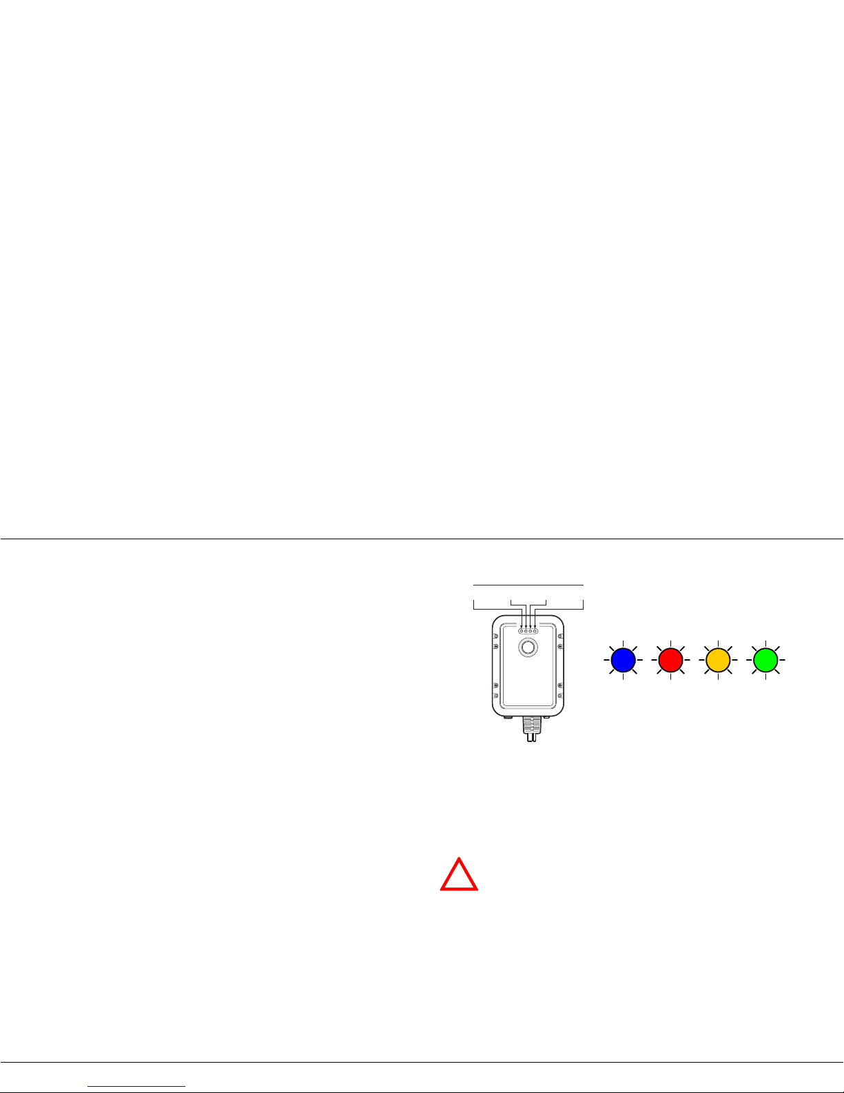
A few seconds after applying power to the Mariner X2 for the first
time all four indicators (green, amber, red and blue) will blink twice.
The indicator sequence following this will depend on whether your
transceive r is pre-configured.
Transceiver is pre-configured:
The amber indicator will illuminate until the transceiver has
transmitted an AIS message.
Transceiver is not pre-configured:
The amber and red indicator will illuminate. This indicates the unit
cannot transmit until it is configured with a valid MMSI.
Figure 13 Indicator start up sequence
Prior to use the Mariner X2 requires programming with the vessel's
static data to ensure that the data transmitted by the Mariner X2
matches that of the host vessel.
Indicator lights
Blue Red Amber Green
!
US Customers only: It is a violation of the rules of the
Federal Communications Commission for the end user
to programme the st a tic data. The static data m ust o nly
be programmed by a competent installer. If your
Mariner X2 has not been preconfigured for you please
refer to your dealer for advice on how to have the
Mariner X2 configured by a competent installer.
Page 19
Configuring your Mariner X2
Page 16
4.2 Introduction to the proAIS software
Included in the CD supplied with your product is a configuration
software tool called 'proAIS'.
proAIS is a software tool which provides the facility to configure,
m
onitor and diagnose issues with your Mariner X2.
Section 4.3 provides instructions on how to install the proAIS
so
ftware.
Section 4.4 describe s ho w to use proAIS to configure the static data
an
d other settings for your Mariner X2.
Section 5.3 describes how to use proAIS to monitor the status of
y
our Mariner X2.
4.3 Installing the proAIS software
This software is designed to be installed and used with a PC
connected to the Mariner X2 via the data lead provided as standard
with the Mariner X2 unit. If the PC b eing used f or pro gramming does
not have a 9-pin serial port then a commercially available USB to
serial adaptor may be re qui red. This connects between the suppli ed
data lead and the PC.
To install proAIS on your PC:
1. Locate and run the setup.exe file on the CD and then follow the
o
n-screen prompts.
2. If a security warning appears, click 'Install' to continue with the
i
nstallation.
3. Once installation is complete, proAIS will launch automatically
a
nd a start menu folder and shortcut will be created for future use.
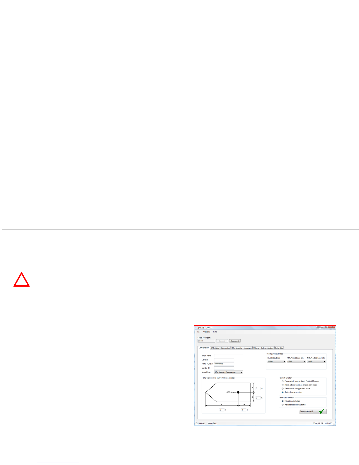
4. Once proAIS has launched you should see a window as shown
in
Figure 14.
5. Please follow the instructions in section 4.4 to configure your
Mariner X2.
Figure 14 Entering static data into proAIS
!
proAIS is only compatible with Windows based
operating systems and is not compatible with Apple
MAC operating systems.
Page 20
Configuring your Mariner X2
Page 17
4.4 Configuration using proAIS
Follow the steps below to configure the Mariner X2:
1. Connect your Mariner X2 to the PC using the RS232 lead as
de
scribed in section 3.2. Apply 12V power to the Mariner X2 as
described in section 3.2.
2. Select the appropriate serial por t in proAIS and p ress 'Conn ect'.
3. proAIS should launch with the 'static data' page active (see
Figure 14). If thi s is not the c ase pleas e select the ' static data' pa ge.
4. Carefully enter the data fields on the screen including:
• MMSI - the vessel's MMSI must be 9 digits in length and should
be t
he same as that used for any other digital radio equipment
such as a VHF DSC radio.
• Ship's name - the ship's name can be up to 20 characters in
len
gth.
• Call sign - the call sign can be up to seven characters in length.
N
ot all vessels are issued with a call sign and it is acceptable to
leave this field blank.
• Vessel type - select a vessel type from the drop down list which
m
ost closely matches your vessel.
• GPS antenna location - use the on-screen guide to specify the
d
istances fro m your G PS antenn a to th e edges of the ve ssel as
shown. The distances are entered in metres.
5. Select the desired switch from the following options:
• Press switch to send safety related message.
• Make switch to disable transmitter (This is required if you intend
to
use an external toggle switch to control silent mode).
• Press switch to toggle transmitter on/off (This is required if you
in
tend to use the integrated switch to toggle silent mode).
• Switch has no function.
Please note: the integrated switch can only provide one of these
f
unctions at any one time. If you wish to change the function of the
switch please return to this configuration process.
6. Set the blue indicator function.
• The blue indicator can be configured to show either the status of
the switch or to show when AIS messages are being received
from other vessels.
• Note that the blue indicator cannot perform both functions
si
multaneously.
!
Please ensure that you enter all static data accurately.
Failure to do so could result in other vessels failing to
identify your vessel correctly.
!
The vessel MMSI can only be programmed once using
proAIS, please take care to programme your MMSI
correctly. If you need to change the MMSI for any
reason, please contact your dealer who will arrange to
have the MMSI reset.
Page 21

Configuring your Mariner X2
Page 18
7. Set the baud rates to the required level for each of the serial
ports.
• Set the RS232 baud rate to the required level. The default is
38,4
00. This is the baud rate used when communicating with a
PC via the RS232 connection.
• Set the NMEA output (transmit) baud rate to the required level.
The default is 38,400. This is the baud rate used when
transmitting data to a chart plotter via its NMEA0183 input.
• Set the NMEA input (receive) baud rate to the required level.
The default is 4,800. If you are using an optional NMEA0183
device such as a heading sensor (see section 3.2) please select
the baud rate at which the NMEA0183 device is transmitting
dat
a. If you are not using an optional NMEA0183 device this
baud rate should be set to the same level as the NMEA transmit
baud rate.
7. Once all dat a h as be en entered correctly , pre ss ' Sav e s t a t ic da t a
to
AIS unit'. This will permanently store the data to the unit.
8. You will see a pop-up window warning you that the MMSI can
on
ly be entered once and should therefore be entered correctly.
Please double chec k you have entered the correct MMSI.
9. All other static data can be modified by repeating the steps
ab
ove.
10.If you need to change the MMSI for any reason please contact
y
our dealer who will be able to reset the unit.
Page 22
Operation
Page 19
5 Operation
5.1 Using the Mariner X2
Once the unit has been configured it is ready for use. Providing
other vessels with Mariner X2s installed are within radio range of
your vessel you shou ld s ee th ei r det a ils ap pea r on y our c ha rt plotter
or PC. These vessel s will also be able to see your vess el on their
chart plotter or PC. It may take up to six minutes for your full vessel
details to be visible to others.
Specific details of ho w to configure your chart plotter to make use of
the Mariner X2 features will be given in your chart plotter manual. If
you are using chartin g s of tw a re run nin g on a PC, plea se refer to the
instructions provided with your chart plotting software for details of
how to configure it to display AIS information.
5.2 Switch functions
The integrated switch on the top of the unit (see Figure 2) can be
configured either to trigger transmission of a "Safety Related
M
essage" or to place the unit into "Silent mode". This choice is
made during configuration of the unit using the proAIS application;
please refer to 4.4 for further information on the configuration
options.
Safety related message
When configured to transmit a safety related message (SRM) the
switch will initiate broadcast of an AIS message containing the
vessels MMSI along with the text "MAYDAY MAYDAY". The switch
must be pressed for at least two seconds to initiate this transmission
(to avoid accidental activation) and the blue indicator will illuminate
to indicate the message has been sent. Further safety related
messages cannot be sent until the blue indicator has extinguished
which will occur one minute after an S RM has been sent.
Silent mode
When configured to place the unit into "Silent mode", each press of
the switch will toggle the AIS transmitter on or off. The switch must
be depressed for two seconds to activate silent mode to avoid
accidental activation. When the transmitter is off, the amber and
blue indicators will be illuminated and the Mariner X2's position will
not be broadcast to other vessels. The position of other vessels will
still be received by the unit.
Silent mode can be used if you wish to only receive AIS messages
f
rom other vessels but keep your own details private from other AIS
users.
!
The SRM function is not a primary means of distress
call and cannot be r elied upon as a means of distress
call.
!
Your vessel will not be displayed on other users, chart
plotters or PCs while your Mariner X2 is in silent mode .
Page 23
Operation
Page 20
5.3 Using proAIS with your Mariner X2
The proAIS tool has a range of features to help monitor the
performance of your Mariner X2. To use the full range of features
your Mariner X2 must be installed as described in section 3 and
connected to a PC running the proAIS application.
proAIS menus
This section describes the functions available via the proAIS
menus.
The proAIS 'File' menu includes the following functions:
Open log file - this includes the ability to open a log file previous ly
captured using the log file capture tool.
The proAIS 'Options' menu includes the following functions:
Beep on AIS transmission - the PC will make an audible beep
when an AIS message is transmitted.
Force connection - fo
rces proAIS to make a connection with the
AIS unit even when no response is received from the unit.
The proAIS 'Help' menu includes the following functions:
About - de
tails of the version number of the proAIS software you
have installed.
proAIS GPS status page
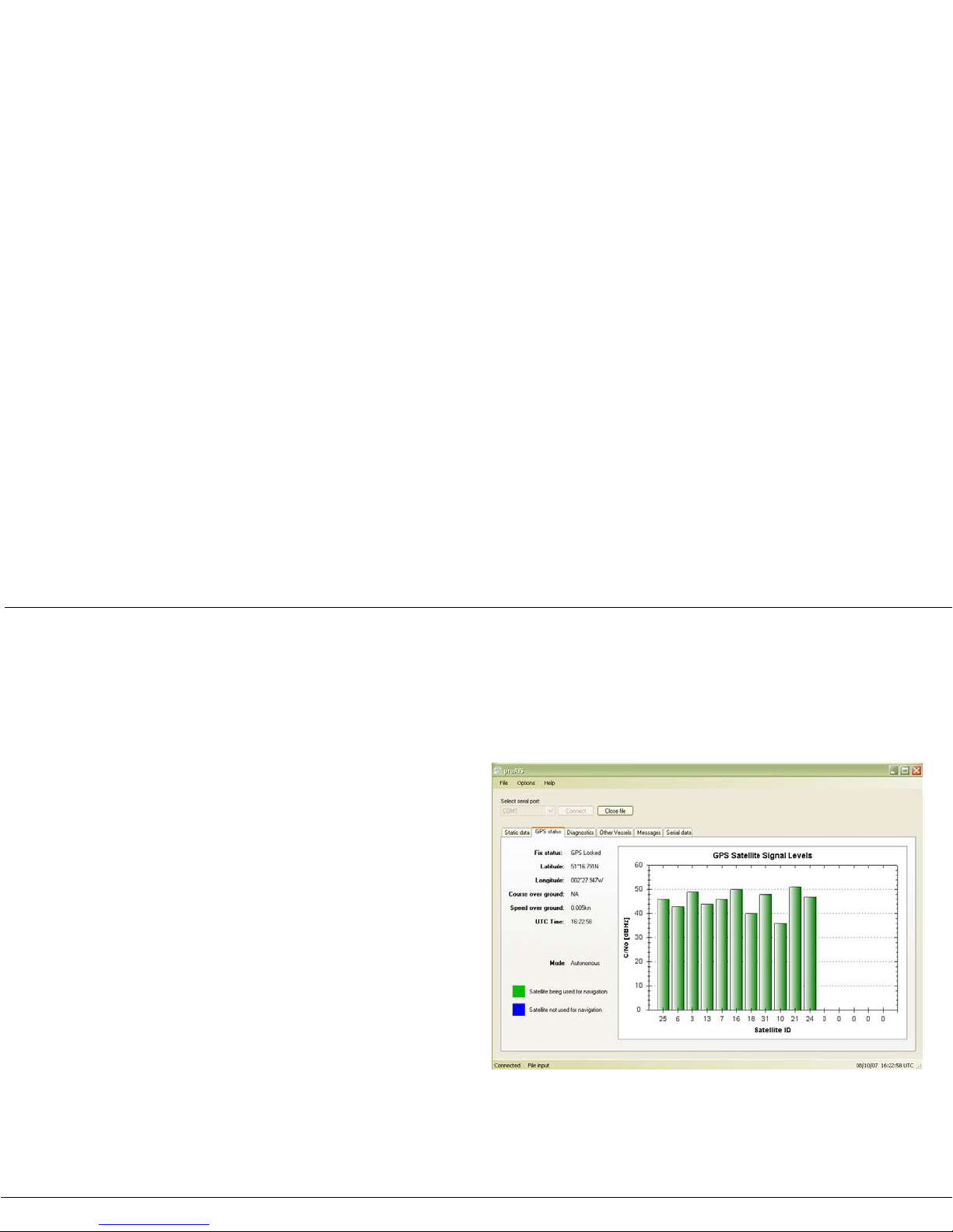
The 'GPS status' page shows the signal strength of each satellite
being received and the dynamic data of the vessel. Satellite signals
shown as green bars are actively being used to calculate a position
fix. If a position fi x c annot be achieved then no dynamic dat a will be
shown and all signal strength bars will be blue.
Figure 15 proAI S GPS status page
Page 24
Operation
Page 21
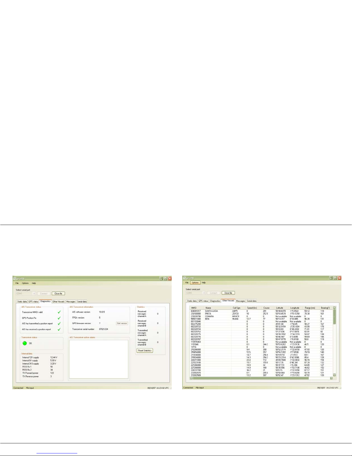
proAIS Diagnostics page
The 'Diagnostics' page provides a range of information about the
Mariner X2's status. Referring to the information in this page may
be useful if you are att emp ting to diagnose a potential issue w i th the
Mariner X2's installation or operation.
Figure 16 proAIS Diagnostics page
proAIS Other vessels page
The 'Other vessels' page provides a list of all vessels from which
AIS messages are being received. For each vessel the MMSI,
name, call sign , speed an d cours e, posit ion, range and bearing are
shown if available.
Figure 17 proAIS Other vessels page
Page 25
Operation
Page 22
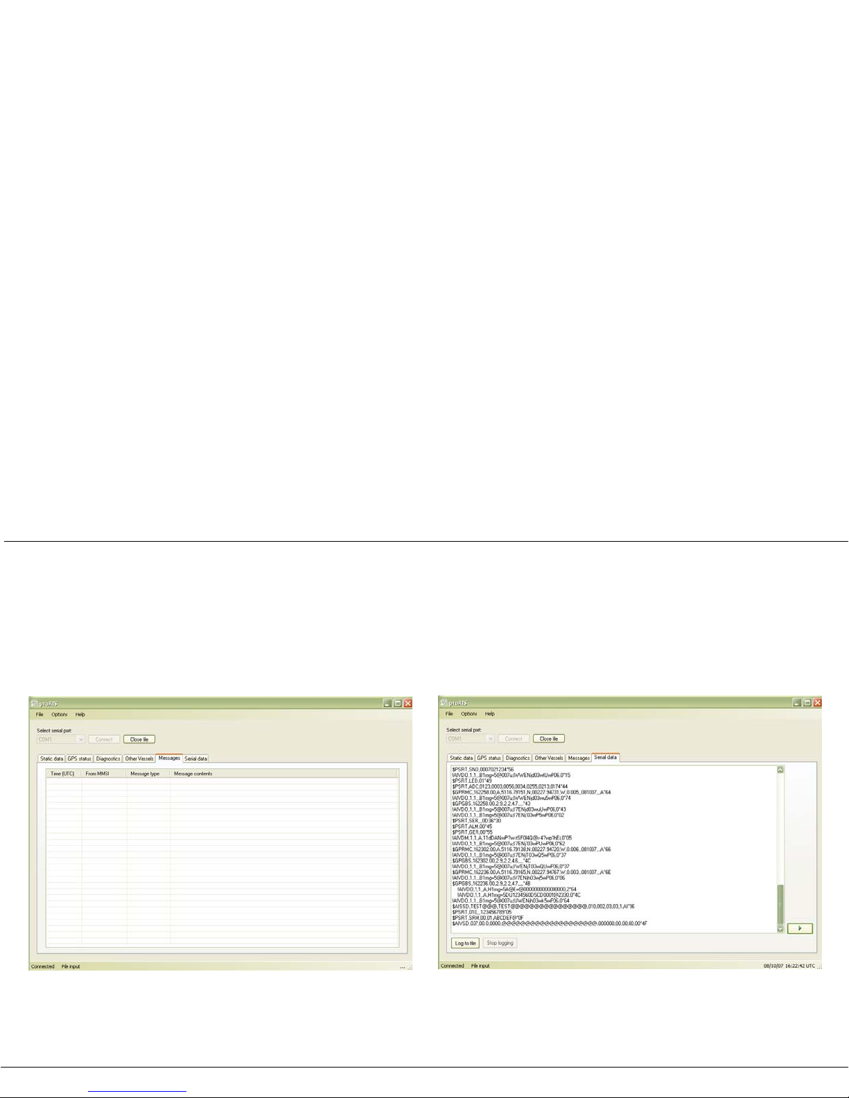
proAIS Messages page
The 'Messages' page provides a list of all text messages received
from other vessels. These are most likely to be safety related
messages which are requests for assistance from other vessels.
Figure 18 proAIS Messages page
proAIS Serial data page
The 'Serial data' page provides a view of all incoming and outgoing
AIS messages. The messag es are e nc ode d in a sp ec ial form at a nd
it is not nece ssary to unders tand the meaning o f the messages t o
use the equipment. The serial data page includes the facility to
capture your AIS data during a journey and then play it back using
the 'open log file' command in the 'File' menu.
Figure 19 proAIS Serial data page
Page 26
Operation
Page 23
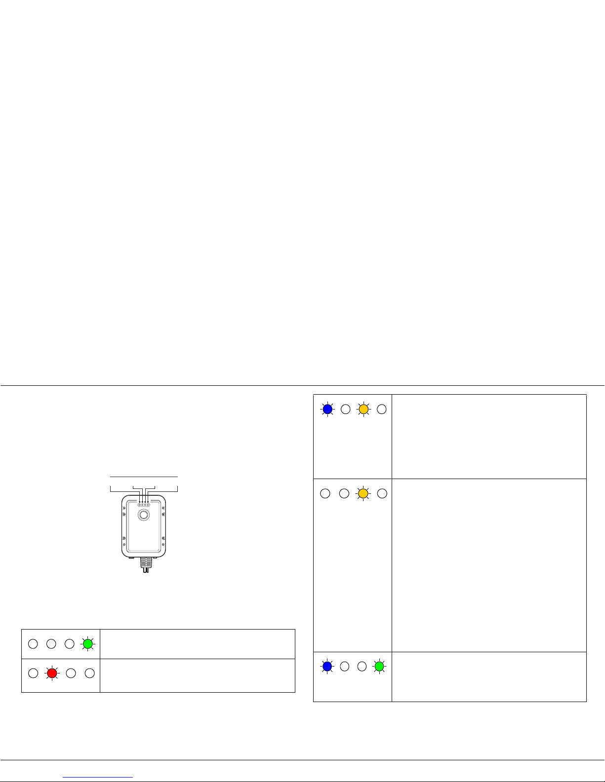
5.4 Indicator functions
The Mariner X2 includ es fou r colo ured in dicat ors as shown in Figure
20. The state of the indicators provides information regarding the
status of the Mariner X2.
Figure 20 Indicator location on the Mariner X2 unit
The meaning of typical indi cat or con fig urations is shown in the table
b
elow and Figure 20 shows the orientation of the Mariner X2.
The Mariner X2 i s power ed up , has a posi tion f ix an d has
transmitted at least one vessel information report.
The Mariner X2 ha s detected a system error. The likely
caus
es of this are detailed in the trouble shooting guide in
section 6.
Indicator lights
Blue Red Amber Green
When the switch function is configured to activate the
silent mode feature and the switch has been depressed
for more than two second s, this combinatio n of indicato rs
will be illuminated to show that the transmitter is disabled.
This arrangement of indicators will also be visible if the
Mariner X2 has b een configured for the blue indicato r to
signify received AIS messages. In this case the blue
indicator will rapidly turn on and off as messages are
received.
The Mariner X2 is i n 'tra nsm i t time ou t' mode. This can be
f
or a number of reasons:
• The unit has only recently been powered on and is
ob
taining a position fix prior to transmitting its first
vessel information report. (This process can take
several minutes).
• Position fix has been lost. The Mariner X2 will attempt
to r
egain position fix for 30 minutes be for e en ter ing a n
error state.
• The AIS radio channels are exceptionally busy so
the
re is currently no available timeslot for
transmission
.
• The unit has been in sile nt mo de an d aft er de act iva ting
silent mode this amber indicator will illuminate until the
first AIS message has been sent
• The Mariner X2 has been commanded by the local
authority (via an AIS Basestation) to ceas
e
tr
ansmissions.
When the switch function is configured to activate safety
related messages and the switch has been depressed for
more than two seconds the blue indicator will illuminate for
1 minute. It is not possible to send a safety related
message at a rate of more than once per minute.
Page 27

Troubleshooting
Page 24
6 Troubleshooting
If the guidance give n in th e table above does not rectify the problem
you are experiencing, please contact your dealer for further
assistance.
Issue Possible cause and remedy
No data is being received
b
y the chart plotter
• Check that the power supply is connected
correctly.
• Check that the power supply is a 12V supply
.
• Check that the connections to the chart plotter are
correc
t.
No indicators are
illuminated
• Check that the power supply is connected
correctly.
• Check that the power supply is a 12V supply
.
The Red 'error' indicator
is illuminated
• T he unit ma y not have a valid M MSI. Check that
the Mariner X2 is correctly configured with a valid
MMS
I.
• T he VHF antenna may be faulty. Please check
t
he connection to the VHF antenna and that th
e
V
HF antenna is not damag ed. The red indicator
may illuminate briefly if the power supply
is
i
nterrupted or the VHF antenna characteristics are
briefly affected
.
• T he GPS antenna may be faulty. Please check
the
connection to the GPS antenna and that the
GPS antenna is not damage
d.
• T he power supp ly is outside t he allowa ble range.
Check that the pow er supply is within t he range
9.6V to 15.6V.
• If none of the above correct the error condition
p
lease contact your dealer for advice.
My MMSI is being
received by other vessels
but my vessel name is
not shown on their chart
plotter or PC
• S ome older A IS devices an d chart plotte rs do not
pro
cess the specific cla ss B AIS message w hich
provides the vessel name (message 24). This is
not a fault of your Mariner X2. Software upgrades
are available for many older chart p lotters which
will correct this issue. The other vessel should
update its AIS unit and /or chart plotting software
to receive AIS message 24
.
Page 28
Specifications
Page 25
7 Specifications
Parameter Value
Dimensions 215 x 150 x 45 mm (L x W x H)
Weight 685g (Mariner X2 unit only)
Power DC (9.6V - 15.6V)
Average power consumption 4W
Peak current rating 2A
GPS Receiver (AIS
Internal)
16 channel IEC 61108-1 compliant
Electrical Interfaces RS232 38.4kBaud bi-directional
RS422 NMEA 38.4kBaud bi-directional
Connectors VHF antenna connector
GPS antenna connector
RS232/RS422/Power/External switch
VHF Transce iv er Transmitter x 1
Receiver x 2 (One receiver time shared
between AIS and DSC)
Frequency: 156.025 to 162.025 MHz in
25 kHz steps
Output Power 33dBm ± 1.5 dB
Channel Bandwidth 25kHz
Channel Step 25kHz
Modulation Modes 25kHz GMSK (AIS, TX and RX)
25kHz AFSK (DSC, RX only)
Bit rate 9600 b/s ± 50 ppm (GMSK)
1200 b/s ± 30 ppm (FSK)
RX Sensitivity Less than -107dBm at 20% PER
Co-channel 10dB
Adjacent channel 70dB
IMD 65dB
Blocking 84dB
Environmental Water resistant to IPx7
Operating temperature: -25ºC to +55ºC
Tested to IEC 60945 'Protected' categor y
Indicators Power, TX timeout, error, status
Operator Controls Single switch configurable to enable
either silent mode or safety related
message functions
 Loading...