

Page 1

Installation & Operation Manual
G7 GNSS Heading Receiver
PN 29010107 V 1.1
Page 2

G7 Installation & Operation
Document PN 29010107 V1r1 - 2 -
Welcome
Congratulations on your purchase of a ComNav G7 GNSS Heading Receiver!
At ComNav, we are dedicated to reliability & quality in all our products, these
products are a good example of that. We promise to do our best to ensure
your satisfaction with your new G7 GNSS Heading Receiver.
Warranty Notice
Prior to the installation and/or operation of the equipment, ensure that you
read, understand, and accept the conditions of the warranties as detailed in
the Warranty Information section of this manual. Additionally, please make
sure you have read and understood all the safety, warnings and caution details
in this manual. ComNav holds no responsibility for incorrect operation by users
and for losses incurred by inappropriate interpretations of this manual.
Additionally, ComNav reserves the rights to update and upgrade the contents
of this guide regularly, and on a regular basis, please consult your local
ComNav dealer for new information or review available latest documentation
downloads via the ComNav website. www.comnav.com
The warranty information section also outlines the Firmware Licensing
Agreement and Limitations on Liability.
General Notice
This document, ComNav part number 29010107 Version 1 Revision 1, is the
approved Installation and Operation Manual for use with G7 GNSS Heading
Receiver. Where versions of this manual exist in other languages, the English
version shall be considered authoritative.
Copyright
ComNav is a registered trademark of ComNav Marine Ltd. All rights and
property are reserved for the respective owner. All product and brand names
mentioned in this publication are trademarks of their respective holders. No
part of this manual may be reproduced, transmitted, or translated into another
form by electronic or other means, without the prior written permission of
ComNav Marine Ltd.
Warning
If your ComNav Model G7 is equipped with a 400 MHz radio, you may be
required to obtain a valid radio license for your region or jurisdiction. Only set
the radio to the frequency and power you are licensed to use at your location.
USA – Federal Communication Commission (FCC)
Radio Frequency radiation exposure information:
This equipment complies with FCC radiation exposure limits set forth for an
uncontrolled environment. The equipment is expected to operate with the
following requirements:
Page 3

G7 Installation & Operation
Document PN 29010107 V1r1 - 3 -
- When using GSM to receive correction data, this equipment
should be installed and operated with a minimum distance of 30
cm between the radio and your body.
- When using 400 MHz SATEL UHF radio, this equipment should
be installed and operated with a minimum distance of 30 cm from
the between the radio and your body.
- The transmitter must not be operating in conjunction with any
other antenna or transmitter.
- If the operation of the equipment is not expressly approved by
ComNav, ComNav, at its sole authority could void the user’s rights
to operate the equipment.
This device complies with Part 15 of the FCC Rules. Operation is subject to
the following conditions: 1) This device may not cause harmful interference
and 2) This device must accept any interference received, including
interference that may cause undesired operation.
This equipment has been tested in accordance and found to comply with the
limits for a Class B digital device, pursuant to Part 15 of the FCC Rules.
These limits are designed to provide reasonable protection against harmful
interference in a residential installation.
This equipment generates, uses, and can radiate radio frequency energy, and
if not installed and used in accordance with the instructions, it may cause
harmful interference to radio communications and equipment. However, there
is no guarantee that interference will not occur in a specific installation.
If this equipment does cause harmful interference to radio reception, which
can be determined by tuning the equipment off and on, the user is encouraged
to attempt to eliminate the interference by one or more of the following
methods:
- Increase the distance between the equipment and receiver
- Reorient or reposition the receiving antenna
- Connect the equipment power outlet on a circuit that is different or
isolated from that to which the receiver is connected.
- Consult the dealer or an experienced radio technician for
assistance
Any modifications not expressly authorized and approved by the party
responsible for compliance could void the user’s authority to operate the
equipment.
Caution: Exposure to Radio Frequency Radiation.
This device must not be positioned in conjunction with any other antenna or
transmitter.
Canada – Industry Canada (IC)
This equipment complies with RSS210 of Industry Canada. Operation is
subject to the following two conditions: 1) This equipment may not cause
interference, and 2) This equipment must accept any interference, including
interference that may cause undesired operation of this equipment.
Caution: Exposure to Radio Frequency Radiation.
The installer of this radio equipment must ensure that the antenna is located or
pointed such that it does not emit RF field in excess of Health Canada limits
for the general population; Safety Code 6, obtainable from Health Canada’s
website.
Page 4

G7 Installation & Operation
Document PN 29010107 V1r1 - 4 -
Europe – Declaration of Conformity
This equipment is in compliance with part 15 of the FCC. Operation is subject
to the following two conditions:
1) This equipment many not cause harmful interference, and
2) This equipment must accept any interference received, including
interference that may cause undesired operation.
This product complies with essential requirements and other relevant
provisions of the Directive 2014/53/EU. This declaration of conformity is
another quality commitment from ComNav.
Page 5

G7 Installation & Operation
Document PN 29010107 V1r1 - 5 -
Technical Support
In order to provide you the best technical support if you cannot find the information in
this manual, whether it be for installation, operation or queries, you are encouraged to
contact your local authorized ComNav technical servicing dealer. To locate the
ComNav authorized dealer near you, please contact:
ComNav
15 – 13511 Crestwood Place
Richmond, BC
Canada
V6V 2G1
Tel # 604 207 1600
Fax # 604 207 8008
[email protected]
Document History
Revision
Date
Description
1
15 March 2018
First Release
About this Manual
This manual provides essential information for the safe and reliable operation
of the ComNav’s G7 GNSS Heading Receiver. Read this manual in its entirety
before using the G7 GNSS Heading Receiver for the first time. Keep the
manual handy until you become thoroughly familiar with the operation of the
Smart Antenna.
Your Comments
Your feedback about this user guide will help us to improve reviews of this
version for development of future revisions. Please email all your comments
to [email protected]
Manual Format
This manual has been formatted to be printed on both sides of the pages of
the manual, and on standard Letter-sized paper (8.5” x 11”).
If you have obtained this manual as a soft-copy, please note that it is in
Adobe® Portable Document Format (“pdf”), and so may be viewed & printed
with Adobe Reader®, or compatible pdf-format viewers.
When printing this manual with Reader, you should select “duplex printing” (or
the equivalent term used by your printer’s software driver), in order to print it
double-sided on the paper. If your printer does not have built-in duplexing
capability, you can still print this manual double-sided by following the
instructions that came with your printer for doing “hand duplexing”.
You should also select the Auto-Rotate and Centre option in the Print Dialog
box, de-select the Choose Paper Source by PDF page size option; as well,
you should set Page Scaling to None – Reader’s default setting is Shrink to
Printable Area, and is printer-dependant (usually set at ~97%), but that is not
needed here.
Page 6

G7 Installation & Operation
Document PN 29010107 V1r1 - 6 -
Table of Content
Welcome .............................................................................................................. 2
Warranty Notice .....................................................................................................2
General Notice .......................................................................................................2
Copyright ................................................................................................................2
Warning ..................................................................................................................2
Technical Support .................................................................................................5
Document History..................................................................................................5
About this Manual .................................................................................................5
Manual Format ..............................................................................................5
Table of Content ............................................................................................. - 6 -
List of Figures ..................................................................................................... 9
List of Tables ..................................................................................................... 11
Overview ............................................................................................................ 15
Installation ......................................................................................................... 17
Tools Required ....................................................................................................17
Power Supply .......................................................................................................17
Environmental Considerations ..........................................................................17
Warnings and Cautions ..................................................................................17
Regulations and Safety ..................................................................................18
Disclaimer Warning ........................................................................................18
Use and Care ...............................................................................................19
General GNSS Reception Considerations ......................................................19
Getting Started with G7 ................................................................................... 20
About the Receiver .............................................................................................20
Parts of the Receiver ..........................................................................................21
Front Connectors ........................................................................................21
Rear Connectors .........................................................................................22
LEDs..............................................................................................................23
Accessories ..........................................................................................................24
Accessory list ...............................................................................................24
Connector definition ....................................................................................26
Additional equipment and software ..................................................................29
Additional equipment ..................................................................................29
Additional Software .....................................................................................30
Environmental Considerations ..........................................................................30
Temperature ................................................................................................30
Humidity ........................................................................................................31
Electronic interference................................................................................31
Power Supply .......................................................................................................31
Page 7

G7 Installation & Operation Table of Contents
Document PN 29010107 V1r1 - - 7 - -
Power adapter .............................................................................................31
Battery ...........................................................................................................33
Mounting the GNSS antennas ..........................................................................34
Antenna Installation Location ....................................................................34
Antenna selection........................................................................................36
Mounting cables ..................................................................................................38
Overview .......................................................................................................38
GNSS Antenna cable .................................................................................39
4G antenna cable ........................................................................................40
Radio antenna cable ...................................................................................41
Aviation plug cable ......................................................................................41
SIM card installation ...........................................................................................42
Card selection ..............................................................................................42
Card installation ...........................................................................................43
Power on & operating check .............................................................................44
Operation ........................................................................................................... 45
Quick start ............................................................................................................45
Functions overview .............................................................................................47
Status ............................................................................................................48
Satellite .........................................................................................................49
Receiver configuration................................................................................50
IO settings ....................................................................................................51
Network set ..................................................................................................52
Module setting .............................................................................................53
Firmware .......................................................................................................54
Work mode setup ................................................................................................56
UHF Rover Settings ....................................................................................56
Rover NTRIP/IP ...........................................................................................59
Base Int. UHF ..............................................................................................62
Data output setup ................................................................................................66
Output Overview..........................................................................................66
Setup webpage............................................................................................70
Care & Maintenance ......................................................................................... 72
Transport ..............................................................................................................72
Storage .................................................................................................................72
Warranty ...............................................................................................................72
Appendices ........................................................................................................ 73
Appendix 1 ...........................................................................................................73
Logging Data................................................................................................73
Specification .................................................................................................77
Glossary ............................................................................................................. 85
Page 8

G7 Installation & Operation Table of Contents
Document PN 29010107 V1r1 - - 8 - -
COMNAV MARINE LTD. FIRMWARE LICENSE AGREEMENT .................... 92
Warranty Information ....................................................................................... 95
Index ................................................................................................................... 99
User Notes ....................................................................................................... 102
Page 9

G7 Installation & Operation Figures & Tables
List of Figures
Figure 1 – Front view of the G7 showing four connectors: GNSS1, GNSS2, 4G and COM. ................................ 22
Figure 2 – Rear view of the G7 showing the UHF radio connector and mini USB port........................................ 22
Figure 3 – Top view of the G7. .................................................................................................................................. 23
Figure 4 – DB9 connector and diagram. .................................................................................................................. 26
Figure 5 – Aviation plug with 19 pins. ................................................................................................ ...................... 27
Figure 6 – Recommended power adapters: Frome left to right: European, North American and British
standard. ............................................................................................................................................................. 32
Figure 7 – Power adapter Exterior. ........................................................................................................................... 32
Figure 8 – Battery Voltage check using a multimeter. ............................................................................................ 33
Figure 9 – Antenna installation on vehicle. ............................................................................................................. 36
Figure 10 – Fully connected G7. ............................................................................................................................... 39
Figure 11 – Dual GNSS antenna connection. .......................................................................................................... 40
Figure 12 – 4G signal enhancement antenna connected to G7. ............................................................................ 40
Figure 13 – UHF radio antenna connected to G7. ................................................................................................... 41
Figure 14 – Aviation plug connected to G7. ............................................................................................................ 42
Figure 15 – SIM card size illustration. ...................................................................................................................... 43
Figure 16 – SIM card compartment. ......................................................................................................................... 43
Figure 17 – Adapter connection. .............................................................................................................................. 44
Figure 18 – Connect to the GNSS-XXXXX WiFi. ...................................................................................................... 46
Figure 19 – Configuration menu when connecting to the G7 via PC. ................................................................... 46
Figure 20 – Language setting. .................................................................................................................................. 47
Figure 21 – Smartphone connection to the G7. ....................................................................................................... 47
Figure 22 – IO settings............................................................................................................................................... 52
Figure 23 – UHF Rover setting using smartphone. ................................................................................................. 57
Figure 24 – Select Auto Rover. ................................................................................................................................. 57
Figure 25 – Set the UHF radio setting. ..................................................................................................................... 58
Figure 26 – UHF Radio setting. ................................................................................................................................. 58
Figure 27 – Connect the G7 to the cellular network. ............................................................................................... 60
Figure 28 – RTK mode setup using NTRIP. ............................................................................................................. 60
Figure 29 – Connect the G7 to the cellular network. ............................................................................................... 61
Figure 30 – Dialing. .................................................................................................................................................... 61
Figure 31 – RTK client setting using NTRIP. ........................................................................................................... 62
Figure 32 – Base Internal UHF radio setting. ........................................................................................................... 63
Figure 33 – Auto base and manual base settings. .................................................................................................. 64
Figure 34 – Radio settings. ....................................................................................................................................... 65
Figure 35 – Differential data settings using Radio. ................................................................................................. 65
Figure 36 – IO output setup for TCP/UDP client, TCP server/NTRIP caster, and serial port setup. .................... 71
Figure 37 – IO setting for Bluetooth, radio and CAN. ............................................................................................. 71
Figure 38 – Set Bluetooth NMEA messages. ........................................................................................................... 73
Figure 39 – Set Serial port messages. ..................................................................................................................... 74
Figure 40 – Connect to G7 via Bluetooth. ................................................................................................................ 74
Figure 41 – Bluetooth COM port. .............................................................................................................................. 74
Figure 42 – Select desired COM port for Bluetooth connection. ........................................................................... 75
Figure 43 – Tera Term terminal showing NMEA sentences. .................................................................................. 75
Document PN 29010107 V1r1 - 9 -
Page 10

G7 Installation & Operation Figures & Tables
Figure 44 – Data logging using Tera Term. .............................................................................................................. 76
Figure 45 – Baud rate setup. ..................................................................................................................................... 76
Figure 46 – Mechanical specification. ...................................................................................................................... 79
Document PN 29010107 V1r1 - 10 -
Page 11

G7 Installation & Operation Figures & Tables
List of Tables
Table 1 – G7 and standard accessories. .................................................................................................................. 25
Table 2 – G7 optional accessories. .......................................................................................................................... 26
Table 3 – DB9 connector pins. .................................................................................................................................. 27
Table 4 – Aviation plug connector and pin assignment. ........................................................................................ 29
Table 5 – Power adapter specification. .................................................................................................................... 33
Table 6 – Recommended antenna specifications. .................................................................................................. 38
Table 7 – GNSS status table. ..................................................................................................................................... 48
Table 8 – Satellite menu. ........................................................................................................................................... 50
Table 9 – Receiver configuration options. ............................................................................................................... 51
Table 10 – Network setting menu. ............................................................................................................................ 53
Table 11 – Module setting menu. .............................................................................................................................. 54
Table 12 – Firmware setting menu. .......................................................................................................................... 55
Table 13 – Data protocol description and output rates. ......................................................................................... 69
Table 14 – Connection protocol. ............................................................................................................................... 70
Table 15 – Receiver performance specification. ..................................................................................................... 79
Table 16 – Electrical and environmental properties. .............................................................................................. 81
Table 17 – G7 Data communication. ......................................................................................................................... 82
Table 18 – Troubleshoot the G7. ............................................................................................................................... 83
Document PN 29010107 V1r1 - 11 -
Page 12

G7 Installation & Operation Introduction
Introduction
Document PN 29010107 V1r1 - 12 -
Page 13

G7 Installation & Operation Introduction
The following Acronyms and their respective Definitions are summarized in the following
table for your convenience and familiarity:
AVL Automated Vehicle Locations
Base Station Station providing real time corrections to nearby RTK rovers via
UHF radio or the internet
BeiDou Chinese satellite based navigation system
CDMA Code Division Multiple Access – a cellular network protocol
DHCP Dynamic Host Configuration Protocol
Datalink Device to send RTK corrections to one or more rovers such as
UHF radio or NTRIP (see NTRIP and NTRIP server)
DGPS / DGNSS Differential GPS/GNSS refers to receiver using differential
corrections
EGNOS European Geo-Stationary Overlay System that provides free
differential corrections service over satellite in parts of Europe
Elevation Mask Minimum angle between a satellite and the horizon for the
receiver to utilize that satellite in the specific application
Firmware Embedded software into the receiver that manages the
processing of the receiver and controls the GNSS engine
GALILEO GNSS installed by the European Union and European Space
Agency
GAGAN GPS Aided GEO Augmented Navigation System (India)
GLONASS Global Orbiting Navigation Satellite System implemented by
Russia similar to GPS by USA
GNSS Global Navigation Satellite System. Satellite constellations that
provide autonomous 3D position (latitude, longitude, altitude)
along with precise timing globally
GPS Global Positioning System (GPS) implemented by USA
IMU Inertial Measurement Unit
INS Inertial Navigation System
NASA National Aeronautics and Space Administration (USA)
NMEA National Marine Electronics Association. NMEA 0183 or N2K
are specifications for data protocols for communications between
various marine electronics equipment, such as GNSS receivers
NTRIP Networked Transport of RTCM via Internet Protocol (NTRIP) is a
protocol for streaming GNSS data or RTK corrections over
internet
NTRIP Server NTRIP server sends data from NTRIP source (base station) to
the NTRIP caster.
Mountpoint Specified data streams in NTRIP. Multiple base stations may
send data to an NTRIP caster
Multipath When GNSS signals reach the antenna by two or more paths
causing incorrect pseudorange measurements leading to less
precise GNSS calculations
MMT Multipath Mitigation Technology
PPS Pulse Per Second or Precise Positioning Service
QZSS Quasi Zenith Satellite System developed by Japan
Document PN 29010107 V1r1 - 13 -
Page 14

G7 Installation & Operation Introduction
PSR Pseudorange
RTCM Radio Technical Commission for Maritime Services (RTCM) is
an industry standard to define RTK message formats
RTK Real Time Kinematic is a real time differential corrections
method to provide improved accuracy
SA Selective Availability or Smart Antenna
SBAS Satellite Based Augmentation System providing differential
corrections over a wide area or region
UART Universal Asynchronous Receiver Transmitter
UHF Ultra High Frequency
WAAS Wide Area Augmentation System is a SBAS that provides free
differential corrections over satellite in North American regions
Document PN 29010107 V1r1 - 14 -
Page 15
G7 Installation & Operation Introduction
Overview
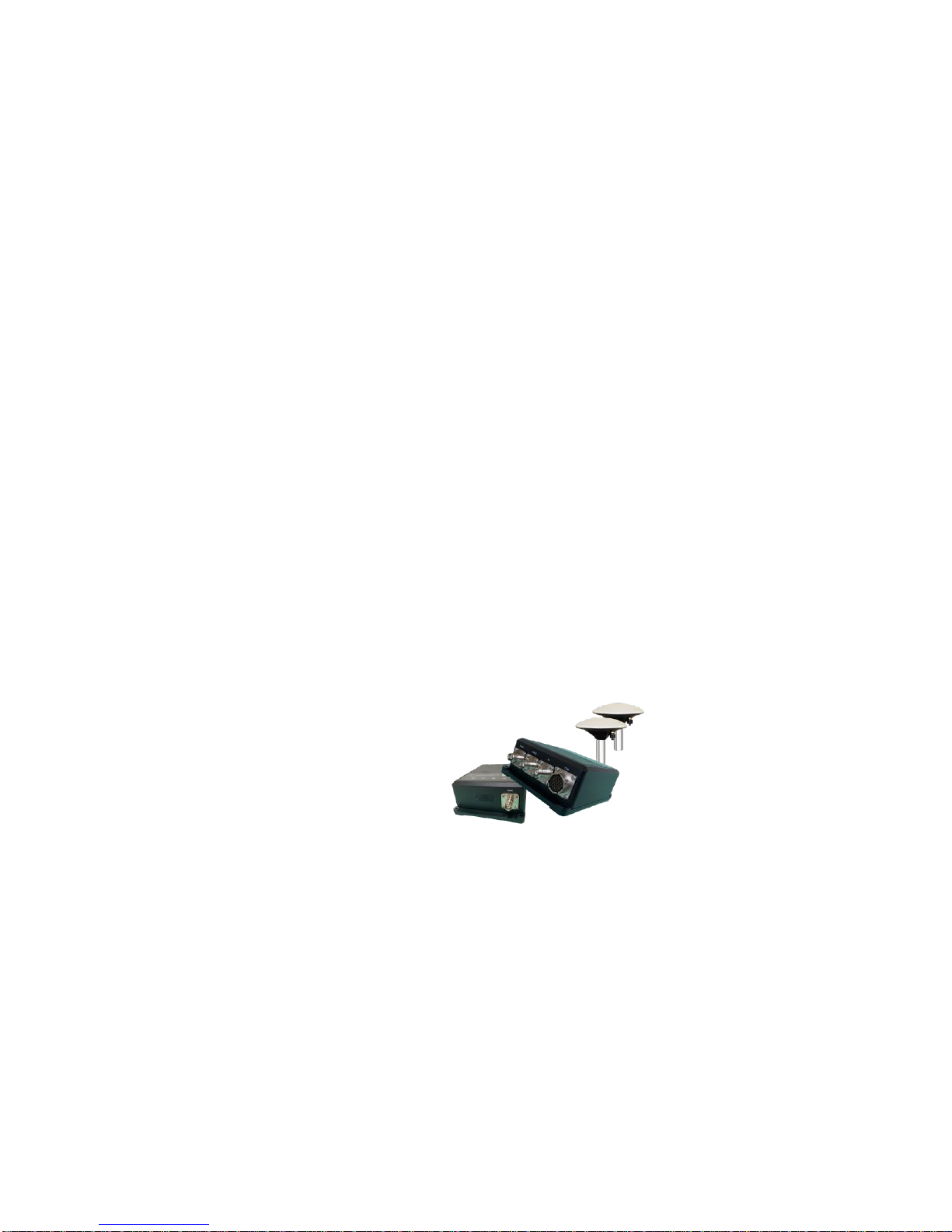
The G7 RTK Receiver with dual GNSS Antennas is a state-of-the-art multi frequency high
precision GNSS RTK receiver capable of up to 1 cm positional accuracy and up to 0.01
degree heading capability in dynamic applications. The precise positioning intelligent
receiver is user configurable to operate as a precise Base Station or to operate as a
Rover in a network. The unit comes in a compact industrial grade package designed for
rugged lightweight universal applications with an internal 32 GB data logging storage
capacity.
The model G7 encompasses multiple wireless communication ports, including WiFi and
Bluetooth, with an embedded UHF SATEL radio along with internal cellular modem for
worldwide coverage to receive corrections data. The unit is also L Band, Trimble RTX /
OmniStar correction service compatible. The device can be configured via web user
interface to control functions, managing data collections, and perform firmware upgrades.
The G7 features fast start-up and signal re-acquisition times, heading & position updates
up to 50 times per second. The G7 is a complete High Precision Antenna in a single
rugged system, with marine-grade enclosures engineered for the most demanding static
and dynamic environment applications.
The model G7 provides world class centimeter level accuracy via RTK corrections on
precise positioning with the accuracy defined by base line distance between the dual
antennas. The units are tested to perform in multi-faceted open sky applications, with
long base lines, and optimal for use in applications such as marine, land, survey,
dredging, GIS, engineering, research, scientific, engineering, machine control,
agricultural, USVs, AGVs and many other specialized situations demanding precise
positioning.
Information in this manual will guide you in adjusting the G7 unit to operate in the best
possible configuration which suits your needs.
Document PN 29010107 V1r1 - 15 -
Page 16

G7 Installation & Operation Installation &Operation
Installation
and
Operation
Document PN 29010107 V1r1 - 16 -
Page 17

G7 Installation & Operation Installation & Operation
Document PN 29010107 V1r1 - 17 -
Installation
Please refer to the Warranty Information section of this manual before
proceeding with installation of the G7.
Tools Required
General-purpose tools such as a portable drill, pliers, wire cutters,
screwdrivers, wire, mounting bolts and wrenches will be required. An accurate
voltmeter or multi-meter would also be useful.
Hazard warning!
Extreme caution is advised when using tools powered
by alternating current (AC) from main supply circuits,
regardless of whether those circuits are rated for
“indoor”, “outdoor”, “marine” or “industrial” use. Water,
especially sea water, is an excellent conductor of
electricity, and can complete a path to AC Ground
through your body, causing injury or death, if a tool
malfunctions or short-circuits.
Battery powered tools are STRONGLY
recommended
If AC tools are used, they must be plugged into a
circuit that is adequately protected against Ground
Faults and other safety hazards, in accordance with
local electrical codes.
Power Supply
NMEA 0183 setup: Unit is powered by the vessel’s or vehicle’s power supply
system and must have an adequate circuit breaker or fuse. Power supply must
be in voltage range of 9 to 36 volts DC. It is recommended to connect the unit
to power via an on/off switch.
Ensure adequate wire sizes are used to handle the expected maximum
currents (see 19).
Environmental Considerations
1. Ensure that the G7’s Operating & Storage Temperature Ranges are
not exceeded (see Specificatio in Appendix 1).
2. The G7 unit operates in an environment with up to 100% relative
humidity. The G7 unit and cable are water resistant – but are not
submersible.
Warnings and Cautions
An absence of specific alerts does not mean that there are no safety risks
involved.
Page 18

G7 Installation & Operation
Document PN 29010107 V1r1 - 18 -
A Warning or Caution information is intended to minimize the risk of personal
injury and/or damage to the equipment.
WARNING – Warning alerts you to a potential misused or wrong setting of the
equipment.
CAUTION – Caution alerts you to possible risk of serious injury to a person
and/or damage to equipment.
Regulations and Safety
The receivers contain a built-in wireless modem for signal communication
through Bluetooth® wireless technology or through external communication
datalink. Regulations regarding the use of the wireless modem vary greatly from
country to country. In some countries, the unit can be used without obtaining an
end-user license. However, in some countries, the administrative permissions
are required. For license information, consult your local dealer. Bluetooth®
operates in license-free bands.
Before operating a G7 GNSS receiver, determine if authorization or a license to
operate the unit is required in your country. It is the responsibility of the end-user
to obtain an operator's permit or license for the receiver for the location or
country of use.
Disclaimer Warning
Before using the G7 receiver, please make sure you have read and understood
this installation and operating instructions and safety requirements pertaining to
your application. ComNav holds no responsibility for wrong operational use of
the G7 including losses incurred by incorrect application. In addition, ComNav
reserves the rights to regularly update and optimize the contents of this manual.
Please consult your local dealer for the latest update and information.
Before operating a G7 GNSS receiver, determine if authorization or a license to
operate the unit is required in your country. It is the responsibility of the end-user
to obtain an operator's permit or license for the receiver for the location or
country of use.
Page 19

G7 Installation & Operation
Document PN 29010107 V1r1 - 19 -
Use and Care
This receiver is designed to withstand the rough environment that typically occurs in the field.
However, the receiver is high-precision electronic equipment and should be treated with
reasonable care.
CAUTION - Operating or storing the receiver outside the specified temperature range will cause
irreversible damage.
General GNSS Reception Considerations
GNSS reception considerations must be considered as follows:
If possible, mount the G7 elevated above all obscuration. Ensure that there is an
unobstructed clear view of the sky when the unit is mounted in order to avoid blocking
of satellites signals.
It is important to position the G7 as far away as possible from any metallic or magnetic
surfaces which could reflect the GNSS satellites signals.
Avoid positioning the G7 within a few meters of any RF signal transmitting antennas
Page 20

G7 Installation & Operation
Document PN 29010107 V1r1 - 20 -
Getting Started with G7
About the Receiver
The G7 GNSS receiver incorporates a GNSS engine, GNSS antenna, internal
radio (403 MHz – 473 MHz), 3G cellular modem, Bluetooth, WiFi module, with
various interfaces such as Ethernet in a ruggedized and miniature unit that is
easy for you to set up for an all-in-one RTK Rover or mobile Base Station.
Bluetooth and WiFi technology provide cable-free communication between the
receiver and controller.
The receiver can also be used as the part of a RTK GNSS system coupled with
COMNAV Data Collection software to download GNSS data recorded in the
internal memory of a receiver for forwarding to a computer. To configure the
receiver for performing a wide variety of functions, you can use the web interface
by connecting the receiver with PC or smartphone via WiFi.
RTK Operation
The G7 automatically tracks satellites in view when powered up with antennas
connected to the ports on the receiver. Position and heading accuracy will
depend on configuration settings, location, and environment. Position
performance will improve with RTK and differential GNSS. Distance between
the dual antennas (baseline distance) will have an impact on heading accuracy.
The differential GNSS and RTK will eliminate the effects of atmospheric errors,
timing errors, and satellite orbit errors while improving system integrity.
SBAS Tracking
The G7 automatically scans and tracks SBAS signals without the need to tune
the receiver. Smart algorithms provide the unit with consistent tracking of SBAS
satellite signals in areas where signal blockage of a satellite is possible. SBAS
selection can be configured and optimized via the software menu display.
Multi-frequency Multi-constellation GNSS
The G7 is designed in its standard form for multi-frequency GNSS to
simultaneously track all in view satellites thereby providing the highest accuracy
and stable (optimized for best possible uninterrupted signals) precision position
and heading at all times. The system optimizes reception of GPS, GLONASS,
Galileo, BeiDou, at all times based on selections configured in the software
menu to provide stable precision heading, position, rate of turn, pitch, roll and
heave at all times.
Page 21

G7 Installation & Operation
Document PN 29010107 V1r1 - 21 -
Precision RTK
RTK requires functional arrangement use of two separate receivers: a stationary
Base Station (primary receiver) that broadcasts corrections over a wireless link
to the Rover (secondary receiver). The G7 is universal and can be intelligently
configured to operate as either a Base Station or a Rover. The G7 can utilize
RTK messages being received via multiple serial communication ports. The
receiver will use any RTK messages over the serial ports if the message type is
in the acceptable specifications list of available differential source
Time Constraints
The G7 has embedded a user configurable time-constraints that can provide a
degree of optimal performance smoothing to heading, pitch, roll, course over
ground (COG), rate of turn (ROT) and speed measurements. This time
constraint parameter adjustment feature is designed to allow for appropriate
damping and monitoring of optimal dynamic performance of the vessel or
vehicle. Such time period parameter adjustments have an impact on damping,
errors, lag, rate, sensitivity and smoother or noisier response.
Parts of the Receiver
The receiver’s front and rear contains the connectors for GNSS, 4G and UHF
radio antenna, USB port, and an aviation plug, while the receiver’s top contain
LEDs for the receiver status and a SIM card compartment.
Front Connectors
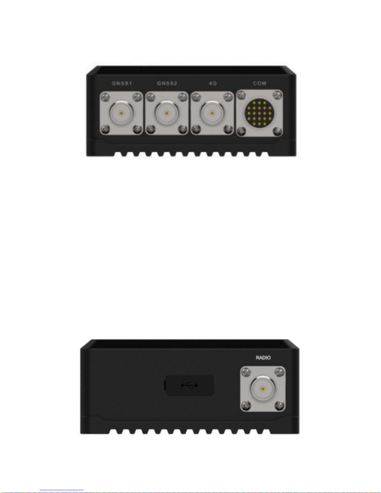
The Figure 1 shows the front view of the receiver. The front panel contains four
connectors namely GNSS1, GNSS2, 4G and COM.
Page 22
G7 Installation & Operation
Document PN 29010107 V1r1 - 22 -
Figure 1 – Front view of the G7 showing four connectors: GNSS1, GNSS2, 4G and COM.
A description of the connectors is as follows:
GNSS1 Connector: TNC male connector for positioning antenna
GNSS2 Connector: TNC male connector for vector antenna
4G Connector: TNC male connector for 4G cellular antenna signal
enhancement
COM Connector: Customize aviation plug for hardware interface
integration. For more details refer to the accessories section below.
Rear Connectors
The Figure 2 shows a rear view of the receiver. The rear panel contains one
TNC connector and one Mini USB port.
Figure 2 – Rear view of the G7 showing the UHF radio connector and mini USB port.
Page 23
G7 Installation & Operation
Document PN 29010107 V1r1 - 23 -
The TNC UHF radio connector is used for connecting a UHF antenna, while the
mini USB port serves various purposed such as downloading saved data to the
PC.
LEDs
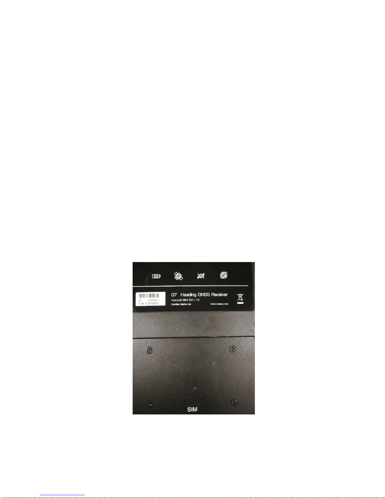
The Figure 3 shows the top view of the G7 receiver. The main panel includes
four different LEDs designed for different receiver status and a SIM card cover
for 4G SIM card installation.
Figure 3 – Top view of the G7.
A description of the LED usage is as follows:
Page 24
G7 Installation & Operation
Document PN 29010107 V1r1 - 24 -
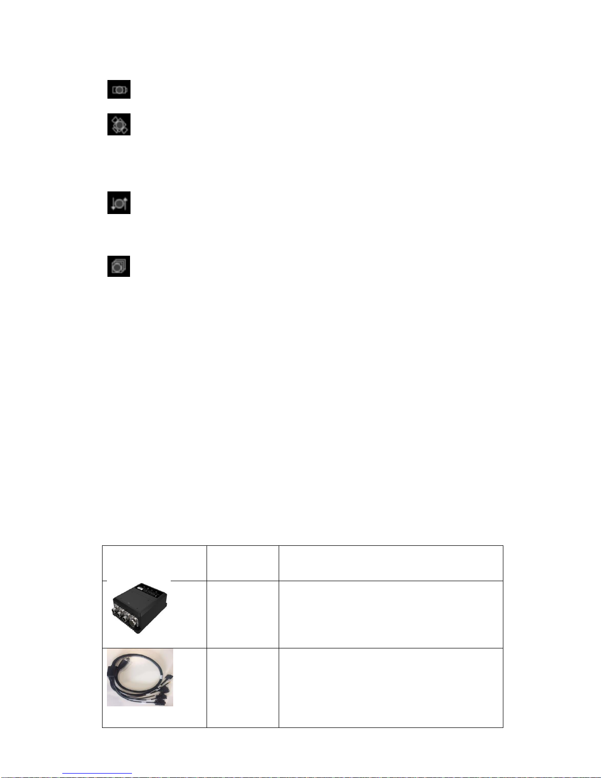
Battery LED: Red color, always on after power-on and off for power-off.
Satellite LED: Blue color, shows the number of satellites the receiver
tracked. When the receiver is searching satellites, this LED flashes once
every 5 seconds. When the receiver has tracked N satellites, the green LED
will flash N times every 5 seconds.
Status LED: Yellow color, indicates the receiver positioning status.
Double flash per second indicates single or differential status, flash once per
second means float and always on means fix status.
Correction LED: Green color, indicates whether the receiver is receiving
differential data. Flash once when receiving a packet of data.
The SIM card compartment contains the SIM card slot. For more information,
please refer to the SIM card installation section.
Accessories
This chapter contains the receiver’s accessories. Before installation, please
make sure that all the accessories meet the required specifications and
standards.
Accessory list
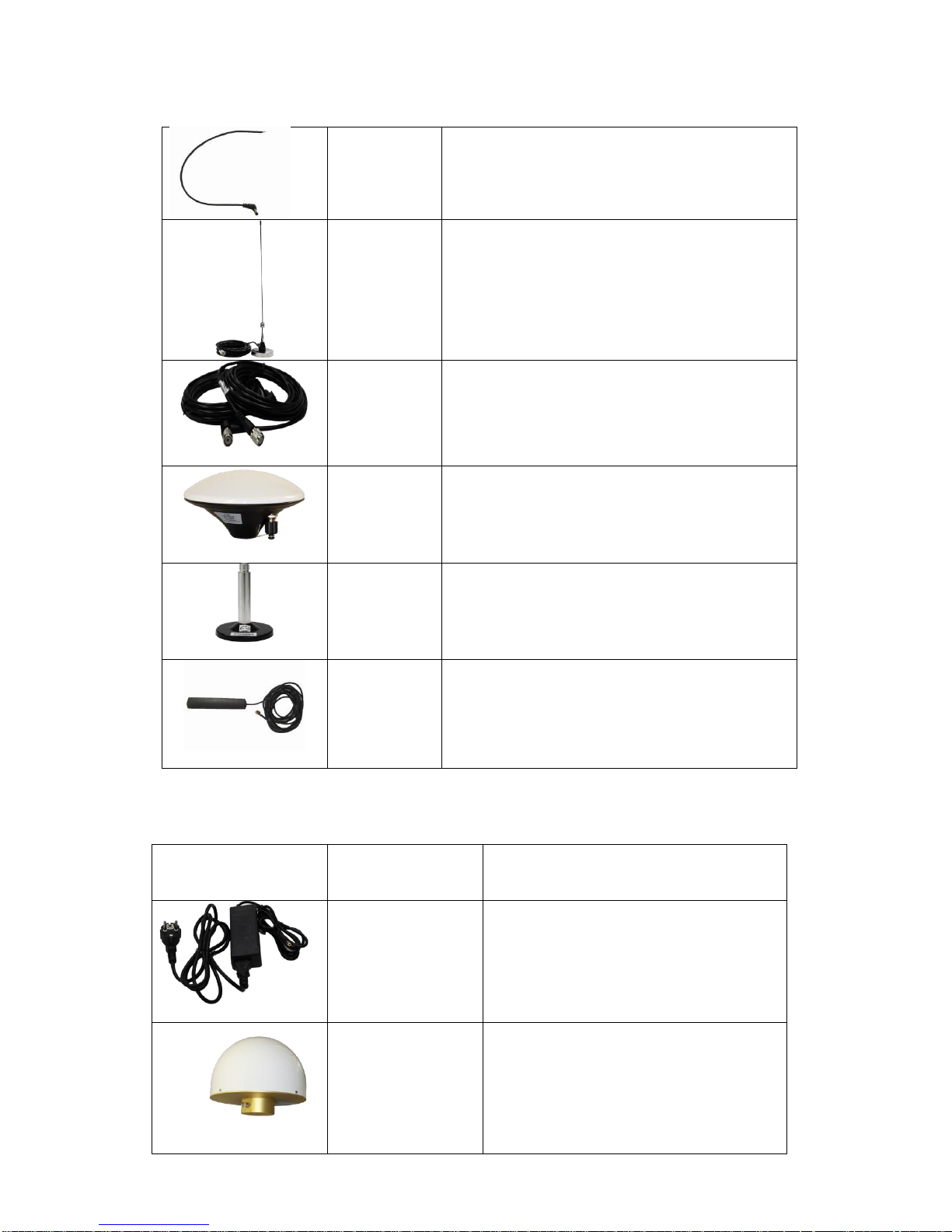
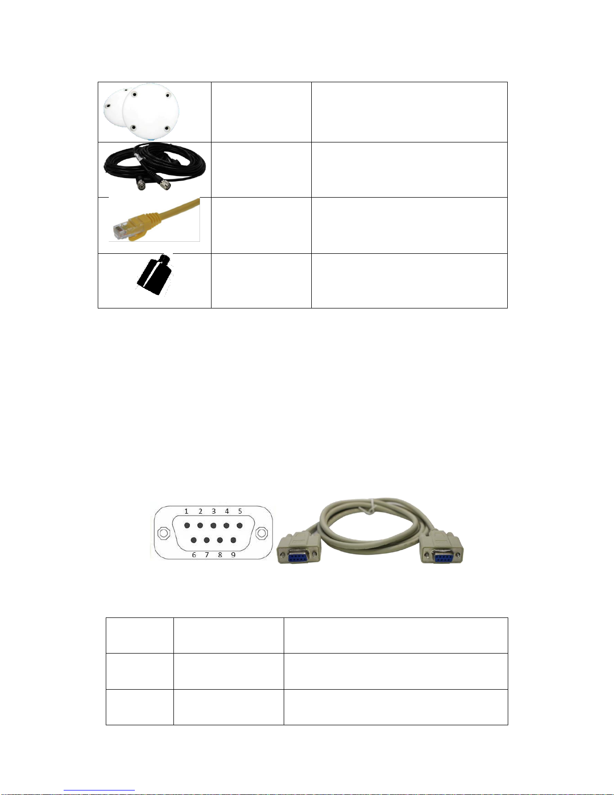
The Table 1 below shows the standard G7 accessories, as well as the optional
accessories that ComNav recommends are shown in Table 2.
Photo
Name
Description
G7
(P/N: 31910005)
GNSS Heading Receiver
19Pin
assembled
aviation
plug
(P/N: 31910020)
Data/power cable
Page 25
G7 Installation & Operation
Document PN 29010107 V1r1 - 25 -
External
power cable
(P/N: 31910022)
Connects the G7 to a DC power source
via the aviation plug
UHF radio
(P/N: 31910023)
UHF radio attached to a magnetic base.
Radio
antenna
connector
(P/N: 31910024)
TNC GNSS antenna cables
GNSS
Antenna
(P/N: 31910030)
Two antennas are supplied
Magnetic
Mount
(P/N: 31910028)
Two mounts are supplied
4G Antenna
(P/N: 31910040)
4G antenna attached to a
magnetic base
Table 1 – G7 and standard accessories.
Photo
Name
Description
Power adapter
(P/N: 31910025)
Power adapter for receiver
Choke ring
antenna
(P/N: 31910041)
C220GR Geodetic Choke
Ring antenna constellation
Page 26
G7 Installation & Operation
Document PN 29010107 V1r1 - 26 -
Aerial antenna
(P/N: 31910026)
B220 geodetic GNSS antenna
constellation
GNSS antenna
cable
(P/N: 31910027)
Two cables, each 10 m long
Network cable
(P/N: 31910021)
5 meter network cable
Mounting adapter
(P/N: 31910029)
5/8’’ to 1’’ mounting adapter for
marine application
Table 2 – G7 optional accessories.
Connector definition
This chapter provides a brief introduction about the hardware interface for the
receiver.
DB9 Female Connector
The DB9 female connector, shown in Figure 4, is an RS232 level port for data
transmission. The pin definitions are shown below in Table 3:
Figure 4 – DB9 connector and diagram.
PIN
Signal Name
Description
1,4,6,7,8,9
Not Used
Not Used
2
TXD
RS232-TX (transmit data through this pin)
Page 27
G7 Installation & Operation
Document PN 29010107 V1r1 - 27 -
3
RXD
RS232-RX (receive data through this pin)
5
GND
External Power Ground
Table 3 – DB9 connector pins.
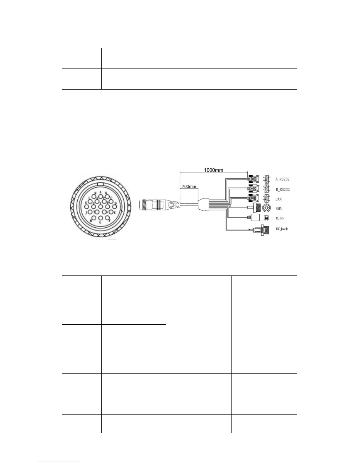
19 PIN aviation plug interface
The 19 PIN aviation plug is customized by ComNav to make the integration of
the G7 convenient and suitable for all kinds of applications. The hardware
interface is shown below in Figure 5, along with a description of the connector
and pin assignment in Table 4.
Figure 5 – Aviation plug with 19 pins.
PIN name
PIN definition
Port type
Port Name
G
3
BD9 female-1
A_RS232
T
5
C
2
M
1
SMA female
SMA
G
Shell/Shield
Page 28

G7 Installation & Operation
Document PN 29010107 V1r1 - 28 -
G
5
BD9 female-2
B_RS232
S
2
D
3
G
6
BD9 female-3
CAN
P
8
E
9
G
3
R
7
F
2
G
RJ45/Shield
RJ45
RJ45
A
3
B
6
U
2
V
1
K
DC Jack
POWER+
Page 29

G7 Installation & Operation
Document PN 29010107 V1r1 - 29 -
L
DC Jack
2A Current
H
DC Jack
POWER-
J
DC Jack
Table 4 – Aviation plug connector and pin assignment.
A description of the connectors is as follows:
A_RS232: DB9 female RS232 port, used for data output from receiver
B_RS232: DB9 female RS232 port, direct connection with built-in
GNSS board
CAN: Can port, work as a can device, used for data output
SMA: PPS signal port, used for PPS time service
RJ45: Ethernet port, used for longing to the webpage from the built-in
GNSS board
DC Jack: power supply port (voltage range: 9 ~ 36V DC )
Additional equipment and software
The following additional equipment and software are required to operate the
G7.
Additional equipment
1. General-purpose tools:
Portable drill, pliers, wire cutters, screwdrivers, wire, mounting
bolts and wrenches.
2. Measuring instrument:
Accurate voltmeter or multi-meter.
3. Power Supply:
Page 30

G7 Installation & Operation
Document PN 29010107 V1r1 - 30 -
External battery (Voltage range: 9 ~ 36V DC ) or power adapter with
cord.
4. Communication Cables:
Serial, USB or Ethernet data cable.
5. Computer or laptop
Additional Software
1. Serial debugging tool:
Used for data output testing and connection confirmation.
2. Network debugging tool:
Used for data output testing
3. Browser recommended:
• Google Chrome
• Microsoft Internet Explorer version 10, or higher
• Apple Safari
Used for webpage login to configure the receiver and built-in GNSS
board configuration.
Environmental Considerations
Temperature
Please make sure that the receiver Operating & Storage Temperature Ranges
are not exceeded.
Operating: -40 °C to +75 °C (-40 °F to +167 °F)
Storage: -55 °C to +85 °C (-67 °F to +185 °F)
Page 31

G7 Installation & Operation
Document PN 29010107 V1r1 - 31 -
Humidity
The receiver is designed for IP67 level for water and dust proof but the
connection between the receiver and power supply is not waterproof and could
be subject to electrical shorting. Please keep the receiver far away from a wet
location or a location that will become wet when the receiver power is on.
Electronic interference
High-power signals from a nearby radio or radar transmitter can overwhelm the
receiver circuits. This does not harm the instrument, but it can prevent the
receiver electronics from functioning correctly.
Avoid locating the receiver or antenna within 400 meters of powerful radar,
television, or other transmitters or GNSS antennas. Low-power transmitters,
such as those in cell phones and two-way radios, normally do not interfere with
receiver operations.
Power Supply
The receiver can be powered by either the power adapter or a battery.
Regardless of the power supply used, please follow the guidelines below:
1. This receiver is not intended to be used in a wet location, or a location
that may become wet when it is powered by the external DC power
supply.
2. The external power adapter and its associated power cord and plug are
not intended to be installed outdoors or in a wet location.
3. Do not power the receiver through external power when operating in a
wet environment or an environment that may become wet. The power
input connections must be sheltered.
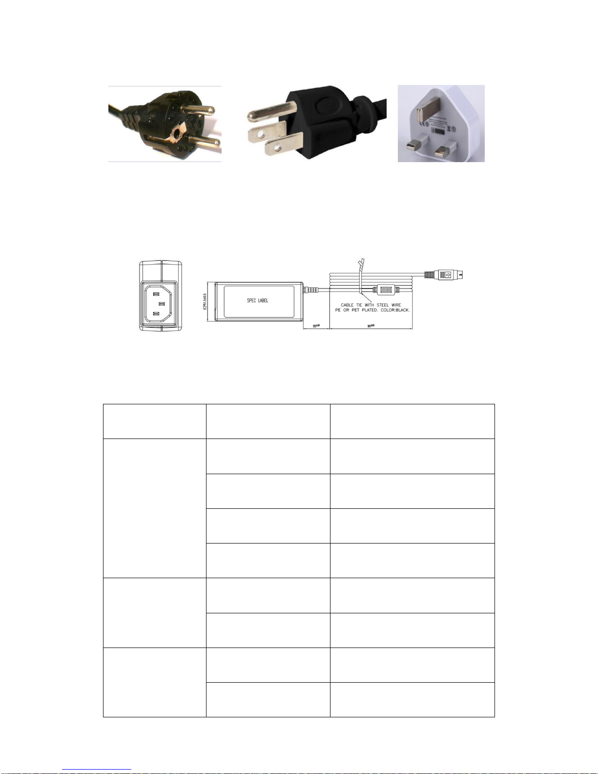
Power adapter
The power adapter is an AC power supply and is used worldwide. Different
cords with appropriate plugs for different countries are supplied with adapter.
The receiver recommended power adapter support three standards namely, the
European, American and British Standard as shown in the Figure 6 below
Page 32
G7 Installation & Operation
Document PN 29010107 V1r1 - 32 -
Figure 6 – Recommended power adapters: Frome left to right: European, North American and
British standard.
Please choose the right power adapter that fits your needs. The Figure 7
shows the power adapter labels, and the corresponding specifications are
shown in Table 5.
Figure 7 – Power adapter Exterior.
Characteristics
Type
Specification
Input
Normal Voltage
100~240V AC
Input Voltage
90~264V AC
Normal Frequency
50~60Hz
Input Frequency
47~63Hz
Output
Rated Voltage
12V DC
Voltage Range
11.4~12.6V DC
Temperature
Operating
-30 °C to +40 °C
Shipping/Storage
-20 °C to +70 °C
Page 33
G7 Installation & Operation
Document PN 29010107 V1r1 - 33 -
Mechanical
Dimension
L*W*H :115*51.5*30.5mm
DC cable length
1200mm
Table 5 – Power adapter specification.
Other types of power adapters can be used to power the receiver, please pay
attention to the adapter specifications, such as the output voltage, operating
temperature and safety requirements.
Battery
The receiver has no built-in battery and can be powered by an external battery
via the power cable.
Before connecting the receiver’s power cable with the battery’s cable clip,
please check that the battery has enough power to power the receiver for the
duration of your work.
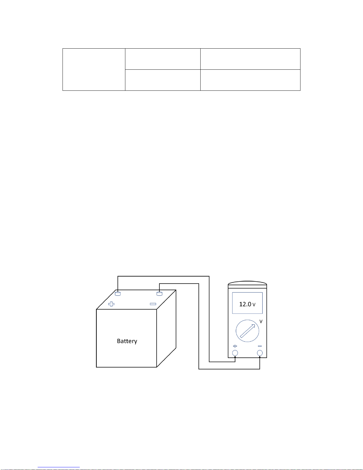
The Figure 8 below shows how to measure the battery’s voltage using a multimeter.
Figure 8 – Battery Voltage check using a multimeter.
When connecting to the battery’s cables clip. Do not allow any metal object or
jewelry to connect (short) the battery's positive (+) terminal to either the negative
(-) terminal. This could result in high current, arcing, and high temperatures,
exposing the user to possible injury.
Page 34

G7 Installation & Operation
Document PN 29010107 V1r1 - 34 -
Mounting the GNSS antennas
The two GNSS antennas connected to the receiver are used to provide both
positioning and heading information. The correct relative position of the two
antennas with respect to one another, as well as with respect to the vehicle’s
body will impact the heading accuracy.
Antenna Installation Location
The selection of the GNSS antenna installation location is essential to the
receiver’s performance. In addition to paying attention to electromagnetic
interference, please follow the guidelines below:
1. Choose an antenna location with a clear view of the sky so each satellite
above the horizon can be tracked without obstruction.
2. Mount the antenna on a secure, stable structure capable of safe
operation in the specific environment.
3. Ensure the antenna cannot move due to dynamics.
4. Mount the primary and secondary antennas as far apart as possible. A
minimum separation distance of 1 meter is recommended.
Mounting Orientation
The G7 outputs position, heading, pitch, heave, and roll readings regardless of
the orientation of the new antennas. The relation of the antennas to the
vessels axis or vehicles axis will determine whether a heading, pitch, and roll
bias needs to be entered.
Parallel Orientation
The typical installation is to orient the antennas in parallel to, and along the
centerline of the axis of the board or vehicle, which results in the unit providing
a true heading. If the vessel has a gyrocompass, one can enter a heading bias
in the G7 to calibrate and match the installed heading to the true heading of the
vessel.
Perpendicular Orientation
The G7 can also be install in such a way so the antennas are oriented
perpendicular to the centerline of the boat’s or vehicle’s axis. In such case, a
heading bias of +90° need to be entered if the primary antenna is installed on
the starboard side of the boat and -90° if the primary antenna is on the port
side of the boat. Alternatively, if a vehicle installation, +90° if the primary
antenna is installed on the right side of the vehicle and -90° if the primary
antenna is on the left side of the vehicle. Additionally, a pitch/roll bias may
have to be entered, and confirmed by independent calibration tests, to properly
output precise pitch and roll values.
Selecting optimal antenna placement
Page 35

G7 Installation & Operation
Document PN 29010107 V1r1 - 35 -
Either one of the two antennas installed is identified as the primary antenna
which is used for positioning. The primary antenna must be installed along the
vessel’s centerline or vehicle’s centerline for accurate positioning. Ideally, the
antennas must be mounted away from metal objects or from other obstructions
that may cause multipath, with a clear view of the sky and horizon, away from
radio frequency interference, radars and other antennas or electronics and in a
horizontal level plane.
Mounting Options
Pole Mount
The pole mount installation of the antenna can be conducted with use of
existing hardware on the vessel or vehicle. Select the mounting location and
orientation by following guidelines in the Mounting Orientation section and
Selecting Optimal Antenna Placement section. The threaded pole base must
be precisely positioned, mounting holes marked and drilled carefully, and
mounted on the vessel or vehicle using non-magnetic corrosion resistant
screws. The bottom of the antenna should be appropriately threaded and
mounted into the pole mount. Warning: When threading the pole mounts, the
antenna should be hand tightened slowly and carefully to avoid any damage
resulting from over-tightening. Overtightening may void the warranty due to
possible mechanical damage.
The standard G7 for marine applications comes with dual marine antennas
with 1” diameter thread for boat vessel pole mount. Alternatively, the standard
G7 for land applications comes with dual geodetic antennas with 5/8” diameter
thread for vehicle rail mount.
Rail Mount
The rail mount installation of the antenna can be conducted with the use of
existing hardware on the vessel or vehicle. Select the mounting location and
orientation by following guidelines in the Mounting Orientation section and
Selecting Optimal Antenna Placement section. Utilize the appropriate
corrosion resistant hardware to securely mount the antenna to the railing.
Magnetic Mount
If you have a vehicle application, and if select to use the magnetic mount
option for antennas, the magnetic mount can be screwed into the bottom of the
antenna mounted to any metal surface. Precisely position the antenna and
thread the magnetic mount into the mounting bracket into the bottom of the
antenna. Warning: When threading the magnetic mount, the antenna should
be hand tightened slowly and carefully to avoid any damage resulting from
over-tightening. Overtightening may void the warranty due to possible
mechanical damage.
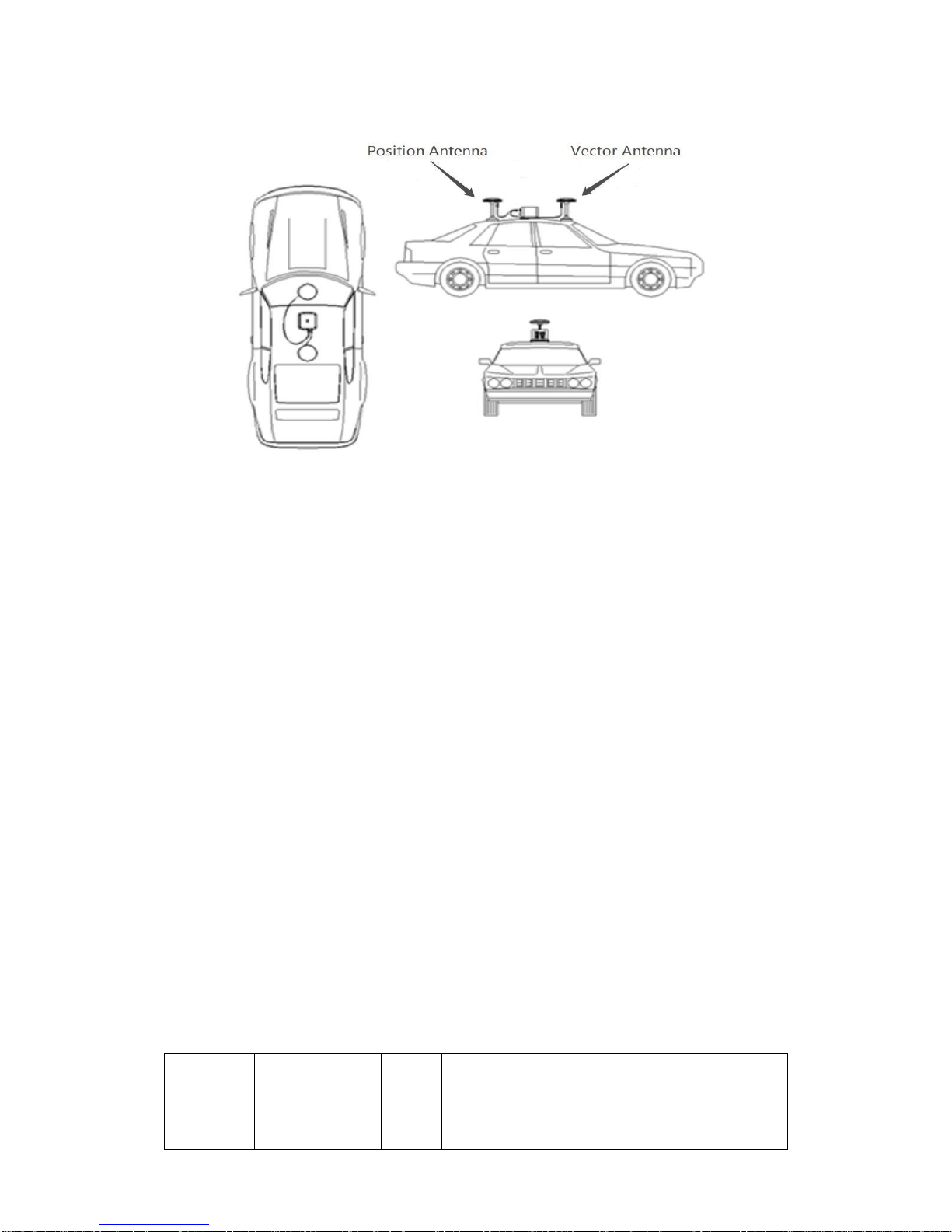
The Figure 9 shows the recommended antenna installation on a vehicle.
Page 36
G7 Installation & Operation
Document PN 29010107 V1r1 - 36 -
Figure 9 – Antenna installation on vehicle.
Please note the following:
1. Position antenna is positioned at the back of the vehicle, and is
connected to the GNSS1 connector of the receiver, and secured to the
vehicle with a magnetic mount.
2. Vector antenna is positioned at the front of the vehicle, and is connected
to the GNSS2 connector of the receiver, and secured to the vehicle with
a magnetic mount.
3. The distance between the two antennas is greater than 1m as
recommended.
4. Ensure that the lines formed by the phase centers of the two antennas
are aligned or parallel with the central axis of the test vehicle.
Antenna selection
An antenna behaves both as a spatial and frequency filter, therefore, selecting
the right GNSS antenna is critical for optimizing performance. An antenna must
match the receiver’s capabilities and specifications, as well as meet size,
weight, environmental and mechanical specifications for the intended
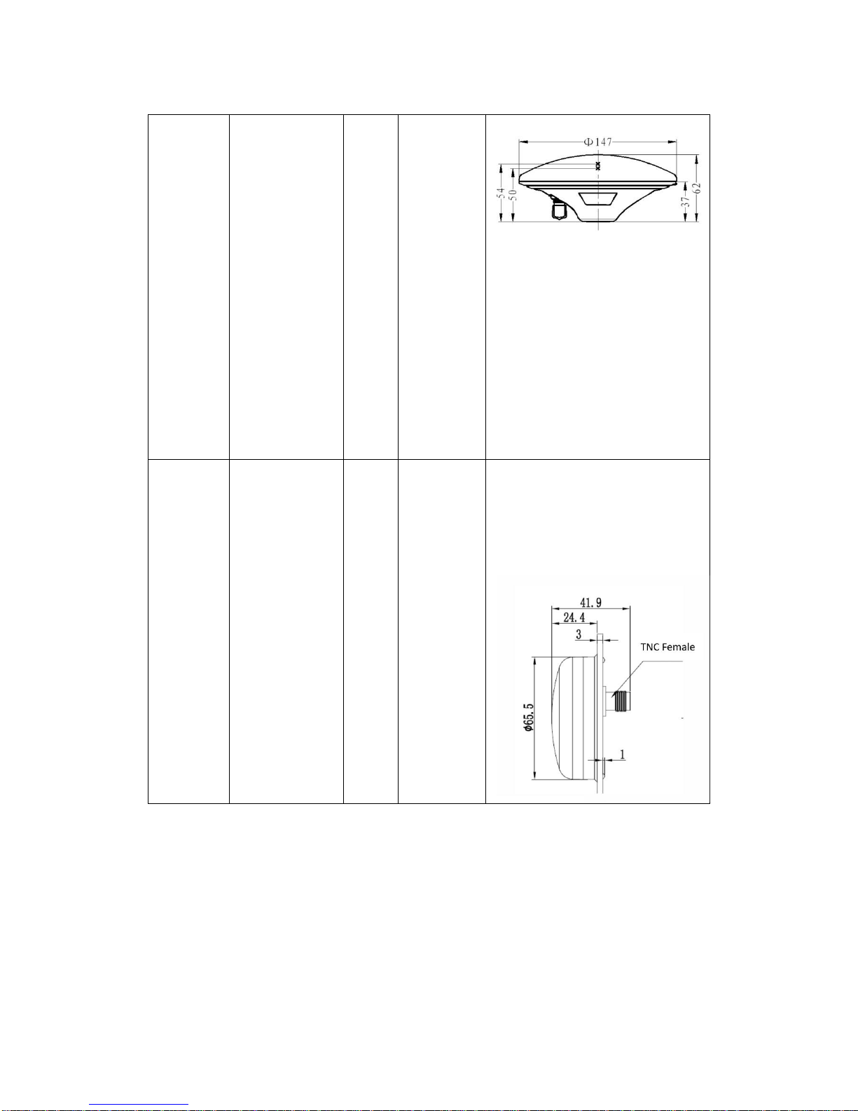
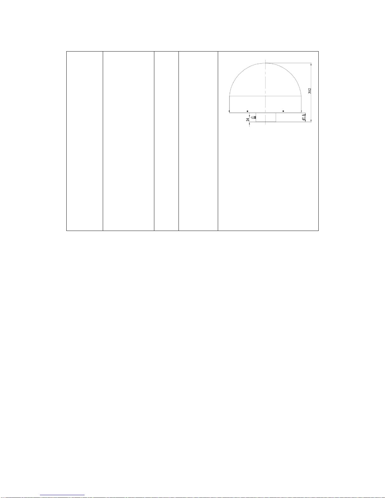
application. There are three kinds of antennas that are recommended to work
with the G7 as described in Table 6 below.
Antenna
Type
Constellation
and signals
Weight
Certification
Size
Page 37
G7 Installation & Operation
Document PN 29010107 V1r1 - 37 -
A230GR
Geodetic
GNSS
Antenna
GPS L1, L2;
GLONASS L1,
L2;
BDS: B1, B2,
B3;
Galileo: E1,
E5a,
E5b;
SBAS: L1 C/A,
L5;
QZSS: L1 C/A,
L1
SAIF, L2C, L5;
0.4kg
NGS
MIL-STD-
810G
IP65
B220
Geodetic
GNSS
Antenna
GPS L1, L2,
L5;
GLONASS L1,
L2;
BDS: B1, B2,
B3;
Galileo: E1,
E5b;
SBAS: L1 C/A,
L5;
QZSS: L1 C/A,
L1
SAIF, L2C, L5;
0.15
kg
IP67
Page 38
G7 Installation & Operation
Document PN 29010107 V1r1 - 38 -
C220
Geodetic
GNSS
Antenna
GPS L1, L2,
L5;
GLONASS L1,
L2;
BDS: B1, B2,
B3;
Galileo: E1,
E2,
E5a, E5b, E6;
SBAS: L1 C/A,
L5;
QZSS: L1 C/A,
L1 SAIF, L2C,
L5;
L-Band;
4.9
kg
IGS
MIL-STD-
810G
IP67
Table 6 – Recommended antenna specifications.
Other GNSS antennas may however be used. Please ensure that the antennas
support the required GNSS frequencies and operates at either 3.3V or 7.1V with
a signal greater than 40 dB at the antenna port.
Mounting cables
This chapter illustrates how to connect the different accessories to the G7.
Please read carefully to avoid installation errors.
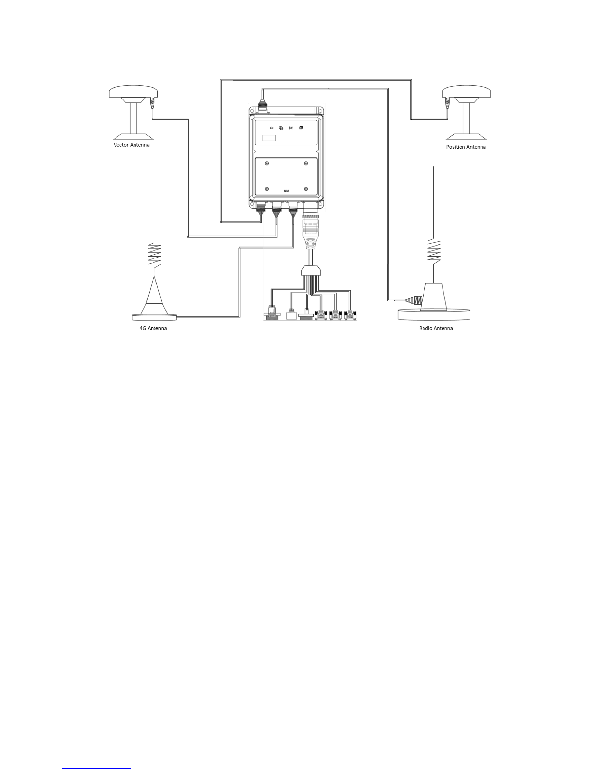
Overview
The full connection between the receiver and the accessories are shown in
Figure 10 below.
Page 39
G7 Installation & Operation
Document PN 29010107 V1r1 - 39 -
Figure 10 – Fully connected G7.
Note that it is not necessary to connect all the accessories as shown in Figure
10 as this depends on the specific project requirements. For example, if the
receiver is not working in radio mode, the radio antenna will not be required.
GNSS Antenna cable
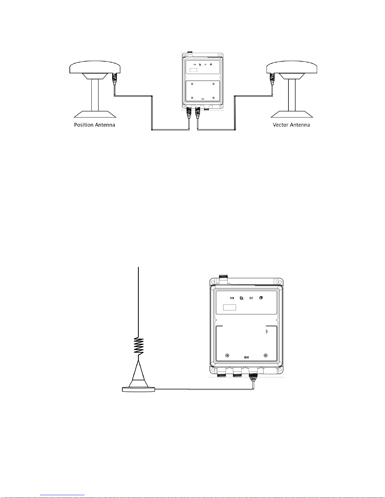
The receiver has two TNC-type male connectors for connecting to the GNSS
antennas. The receiver is intended for use with two ComNav Geodetic GNSS
antennas. Connect the antenna to the TNC plug socket of the receiver via the
GNSS antenna cable as shown in Figure 11. Please note the following tips:
1. Locate the correct two connectors for the GNSS antennas.
2. Choose the proper length of the GNSS antenna cable according to your
application, the standard length of this cable is 5 meters.
3. Make sure the connectors at the receiver and antenna ends are both
tightened.
Page 40
G7 Installation & Operation
Document PN 29010107 V1r1 - 40 -
Figure 11 – Dual GNSS antenna connection.
4G antenna cable
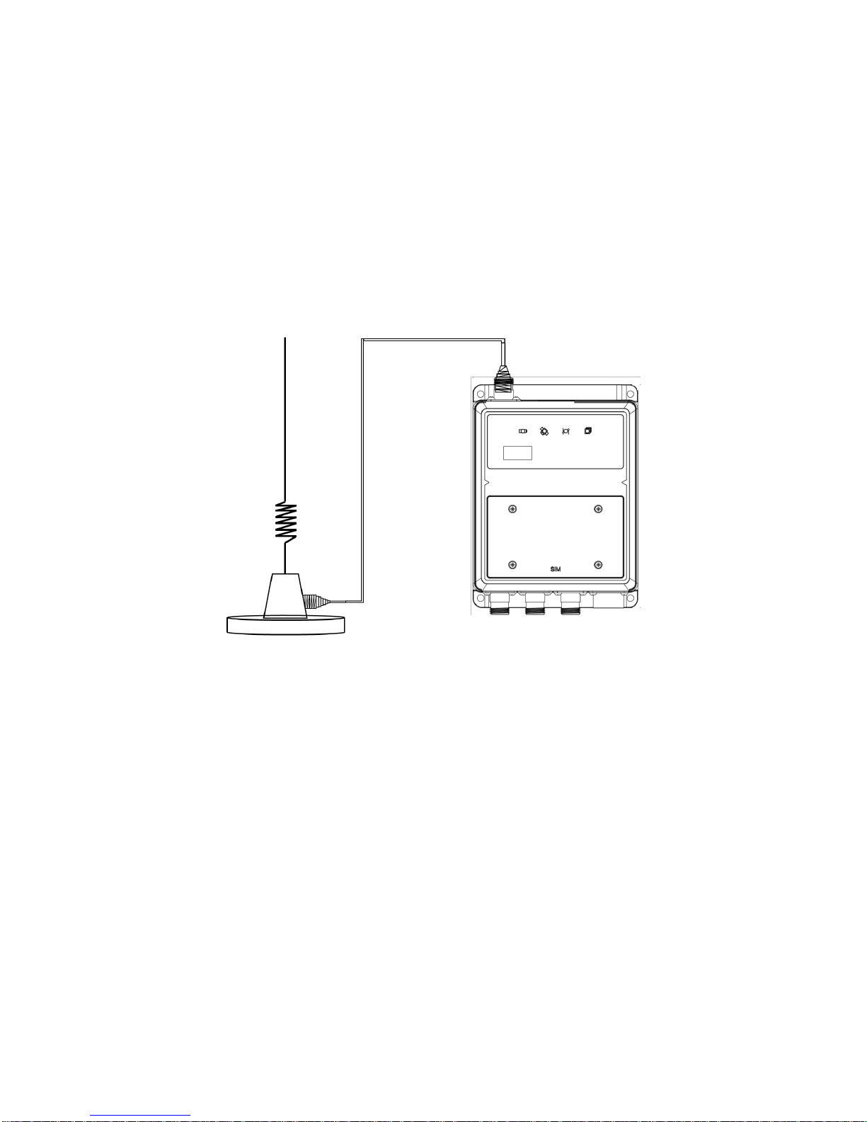
The connection between the 4G signal antenna and the G7 receiver is shown
in Figure 12 below. Please note the following:
1. Locate the correct connector for the 4G antenna.
2. Make sure the connectors at the receiver and antenna ends are both
tightened.
3. Place the 4G antenna in a suitable place, refer to the installation method
of the GNSS antenna.
Figure 12 – 4G signal enhancement antenna connected to G7.
Page 41
G7 Installation & Operation
Document PN 29010107 V1r1 - 41 -
Radio antenna cable
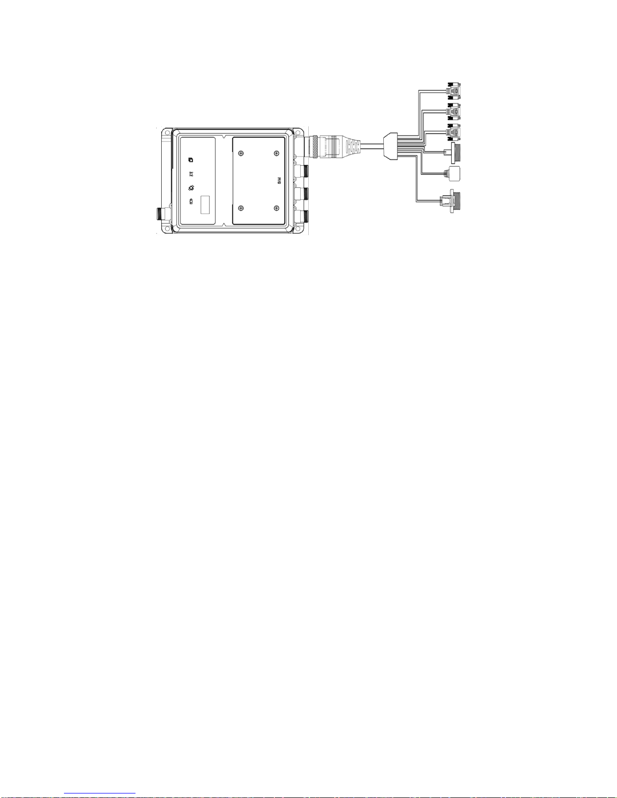
The connection between the external radio antenna and the G7 receiver is
showed in Figure 13 below.
1. Locate the correct connector for the radio antenna.
2. Make sure the connectors at the receiver and antenna ends are both
tightened.
3. Place the radio antenna in a suitable place, refer to the installation
method of the GNSS antenna.
Figure 13 – UHF radio antenna connected to G7.
Aviation plug cable
The connection between the aviation plug cable and the G7 receiver is shown
in Figure 14. Please follow the steps below to make the connection finished.
1. Align the grooves in the connector and projections of the aviation plug cable.
2. Pull the plug into the connector about 5 millimeters.
3. Pull the locker forward to the head of the plug and rotate it to the connector.
Page 42
G7 Installation & Operation
Document PN 29010107 V1r1 - 42 -
Figure 14 – Aviation plug connected to G7.
After installation, please follow the instructions below to re-confirm the
installation once again:
1. Ensure that the system components are securely mounted and will not
shake loose due to the vibrations.
2. Ensure that the cable to the receiver is well secured with clamps or
alternative fasteners.
3. Ensuring that cabling and wiring do not cause any strain on the
connectors.
SIM card installation
The SIM card compartment houses the SIM card slot. The compartment is fixed
by four screws. Please read this chapter carefully before installing the SIM card
for the first time to protect the SIM card slot from being damaged.
Card selection
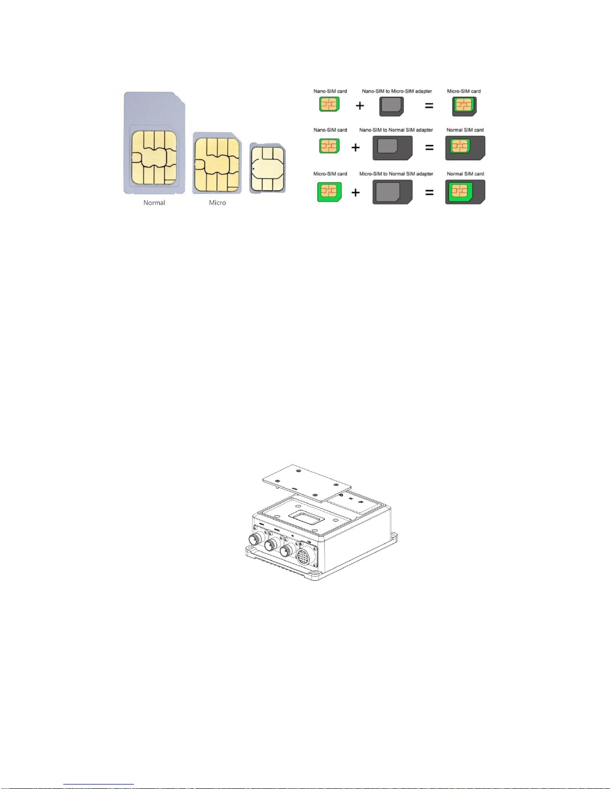
Before installation, the correct SIM card should be prepared. The Correct SIM
card size is Micro as shown in Figure 15 below.
Page 43
G7 Installation & Operation
Document PN 29010107 V1r1 - 43 -
Figure 15 – SIM card size illustration.
The Normal size card should be cut to the Micro size before inserting it into the
SIM card slot. Similarly, the Nano size card can also be used with a special
adapter to convert it to Micro. However, these two methods are not
recommended.
Card installation
The following steps show the installation method of the SIM card, please follow
these steps when you make the installation for the first time.
1. Disconnect the power to the receiver, the installation should be carried out without
power supply.
2. Unscrew the four fixing screws in the SIM card cover with screwdrivers, after the
cover is removed, the SIM card slot will appear as shown in Figure 16 below
Figure 16 – SIM card compartment.
3. Follow the direction of opening in the slot to unlock the locker to get SIM card in at
proper position then close the locker and follow the direction of locking to get it
locked. Be careful not to use too much force to the locker.
Nano
Page 44
G7 Installation & Operation
Document PN 29010107 V1r1 - 44 -
4. After the SIM card is fixed and the slot is locked, screw the four fixing screws in the
SIM card cover with screwdrivers. Please make sure the four screws are tightened
well.
5. Power on the receiver and set it to work in the mobile network mode using the built-in
webpage.
Power on & operating check
Connect one end of the external power cable to the aviation plug DC jack. The
external power cable end should be inserted into the aviation plug DC jack and
fastened by rotating the wheel clockwise.
Connect the other end to a power supply. The receiver supports both external
battery power and adapter power supply. Please follow the following steps
when you power on the receiver for the first time.
For the external battery power:
3. Check the battery level with a multi-meter.
4. Connect the corresponding positive/negative terminals of the battery to
the external power cable positive and negative terminals.
5. Connect the external power cable to the aviation plug DC jack port.
For the adapter power supply:
1. Plug the adapter plug into an electrical outlet and turn on.
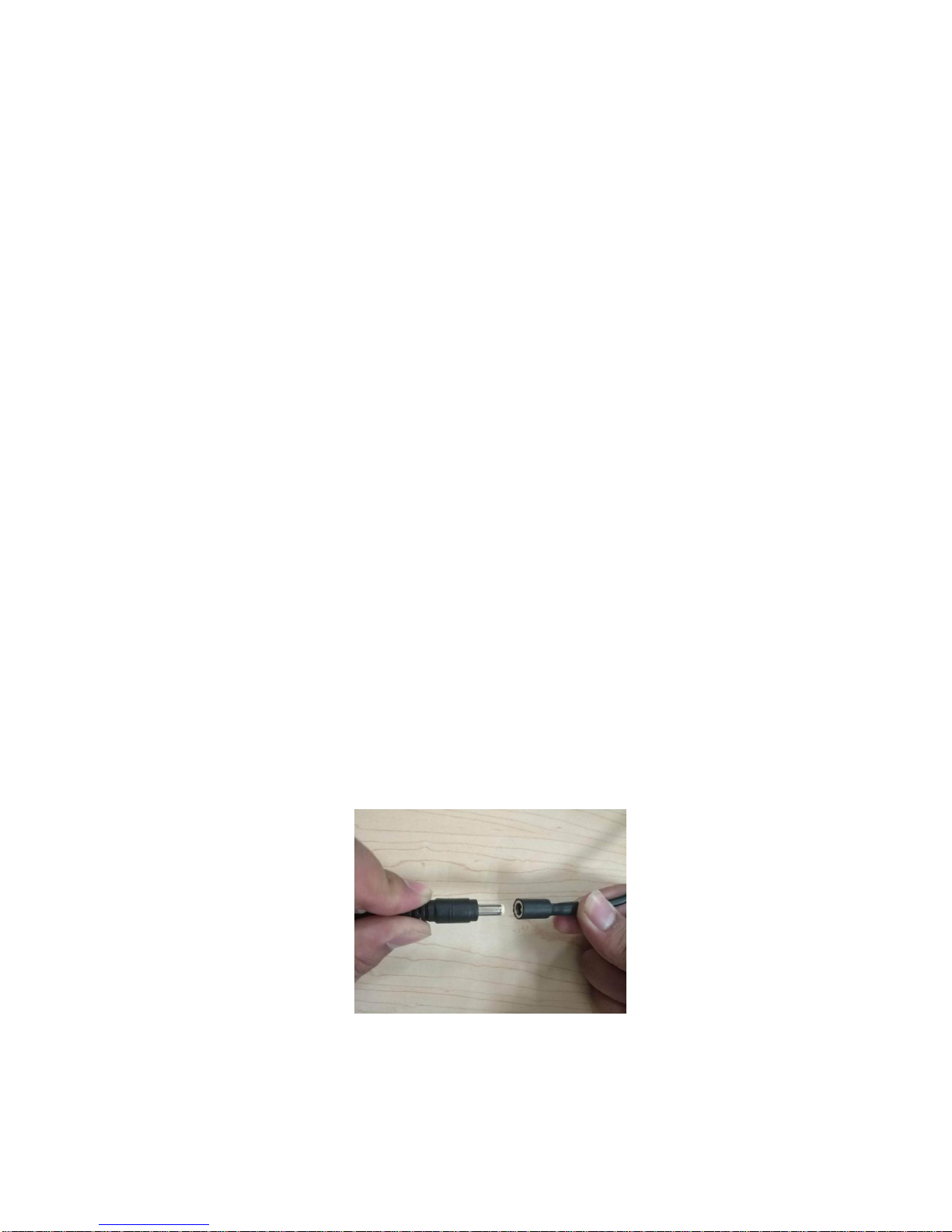
2. Insert the adapter output port into the aviation plug DC jack port as
shown in Figure 17.
When the power is supplied properly to the receiver, the following phenomena
should be observed if the system is running properly.
1. The four LEDs light up at the same time and lasts for ten seconds.
Figure 17 – Adapter connection.
Page 45

G7 Installation & Operation
Document PN 29010107 V1r1 - 45 -
2. After ten seconds, the power LED will still be on showing a solid red color
and the three other LEDs will be off.
3. The status LED will flash twice per second in yellow color.
4. The Bluetooth and WiFi for the receiver can be searched and connected
to.
5. The satellite LED will flash in blue color if the GNSS antennas have been
connected to the receiver.
Operation
This chapter describes the operation for setting up the G7 receiver using the
web interface. This includes configuring the receiver work mode, data output
setup as well other settings.
Please make sure the receiver is powered on and running normally before
modifying the settings.
Quick start
After connecting the antennas and cables, power on the receiver. Once the
receiver is running, connect to it using WiFi to configure and monitor the
receiver settings. No cable connection to the receiver is required. Please follow
the following steps to get started connecting to the receiver’s webpage via WiFi.
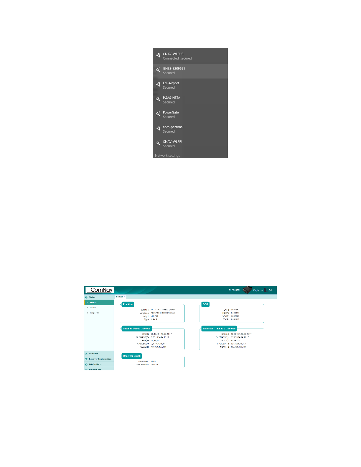
1. Using the WiFi connection application on your PC or smartphone, find the access
point SSID of the receiver. Search the WiFi network named as GNSSXXXXXXX
(where XXXXXXX represents the SN of your receiver) on your computer or
smartphone, and then establish the connection (See Figure 18 as an example)
Page 46
G7 Installation & Operation
Document PN 29010107 V1r1 - 46 -
Figure 18 – Connect to the GNSS-XXXXX WiFi.
2. Open your web browser and then type the receiver IP address into the URL field. By
default, the IP address of the receiver is http://192.168.200.1.
3. The web browser prompts you to enter a login account and password. By default, the
login account is admin and the password is password.
If you tick remember me option, the browser will remember the Login Account
and Password you entered for next time login.
Once logged in, the web page shows the configuration menus on the left of the
browser window (see Figure 19), and the setting on the right. Each configuration
menu contains the related submenus to configure the receiver and monitor the
receiver performance.
Figure 19 – Configuration menu when connecting to the G7 via PC.
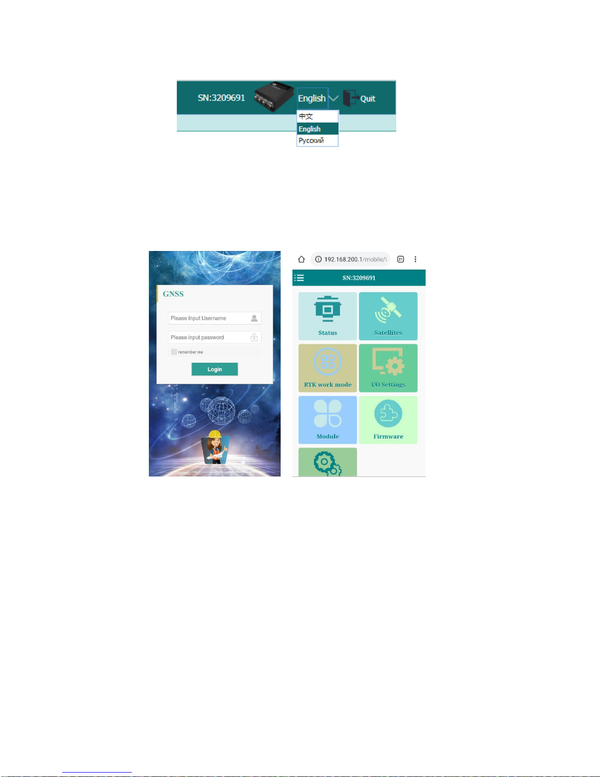
To view the web page in another language, select the corresponding language
name from the dropdown list on the upper right corner of the web page.
Currently, three languages are available:
Page 47
G7 Installation & Operation
Document PN 29010107 V1r1 - 47 -
Figure 20 – Language setting.
The built-in webpage will show in a different style as the shown in Figure 21
when you log in from a smartphone’s web browser.
Figure 21 – Smartphone connection to the G7.
Two kinds of webpage version are designed in the receiver firmware, one is the
computer version and the other is the smart phone version. For more
information about these two different webpages, please read the chapters
below carefully.
Functions overview
The receiver’s firmware is designed to integrate many functionalities to make
the receiver adaptable in all kinds of applications. This provides a convenient
way to control the receiver via the built-in webpage using a PC or smartphone.
This chapter describes the computer/PC version of the webpage.
Page 48
G7 Installation & Operation
Document PN 29010107 V1r1 - 48 -
The following configuration menus are available.
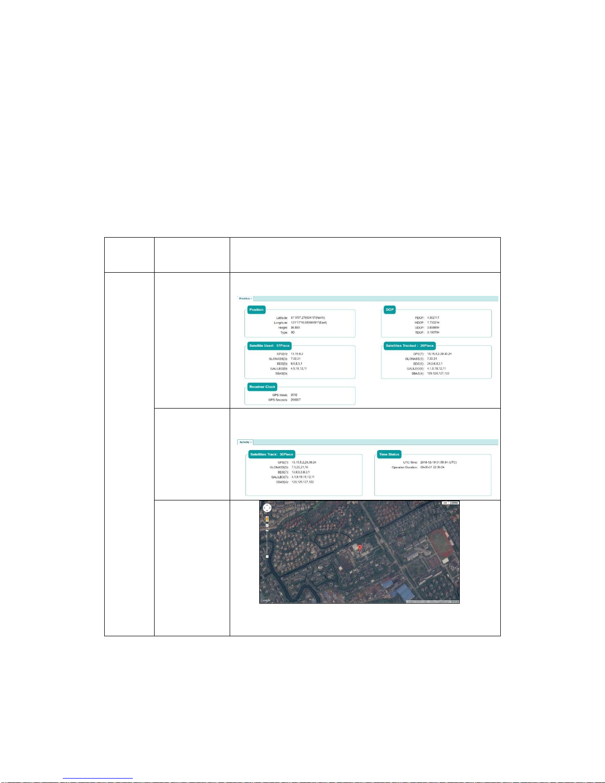
Status
The Status menu includes three submenus, namely, Position, Activity and
Google map. Each submenu contains different information as shown in Table 7
below.
Menu
Submenu
Information
Status
Position
Activity
Google map
Table 7 – GNSS status table.
Position: This page contains Position, DOP, Satellite Used, Satellite tracked
and Receiver clock information. Position with latitude, longitude, height and
position status. DOP value in P/H/V/T type. Satellites for
GPS/GLONASS/BDS/GALILEO/SBAS constellation used and tracked both.
GPS week and GPS second for the clock information.
Page 49
G7 Installation & Operation
Document PN 29010107 V1r1 - 49 -
Activity: This page includes satellite track information and time status
information for UTC time and the receiver running time.
Google map: Allows you to view the receiver location via google map.
Satellite
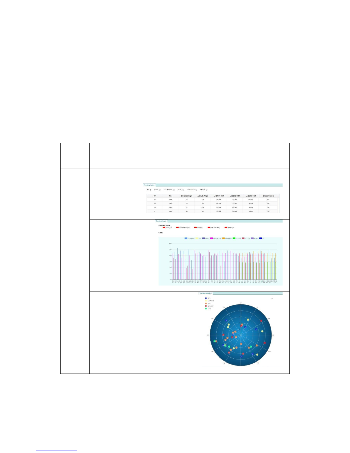
The Satellite menu shown in Table 8 contains the Tracking table, Tracking
graph, Tracking skyplot and Satellite activation submenus.
Menu
Submenu
Information
Satellite
Tracking
table
Tracking
graph
Tracking
skyplot
Page 50
G7 Installation & Operation
Document PN 29010107 V1r1 - 50 -
Satellite
activation
Table 8 – Satellite menu.
Tracking Table: Shows the satellites being tracked along with their
characteristics i.e. constellation, elevation, SNR.
Tracking Graph: Shows the satellites being tracked plotted as a graph, where
the vertical axis is the SNR (in dB) and the horizontal axis is the Satellite.
Tracking skyplot: Shows the satellites being tracked plotted as a 360 plot.
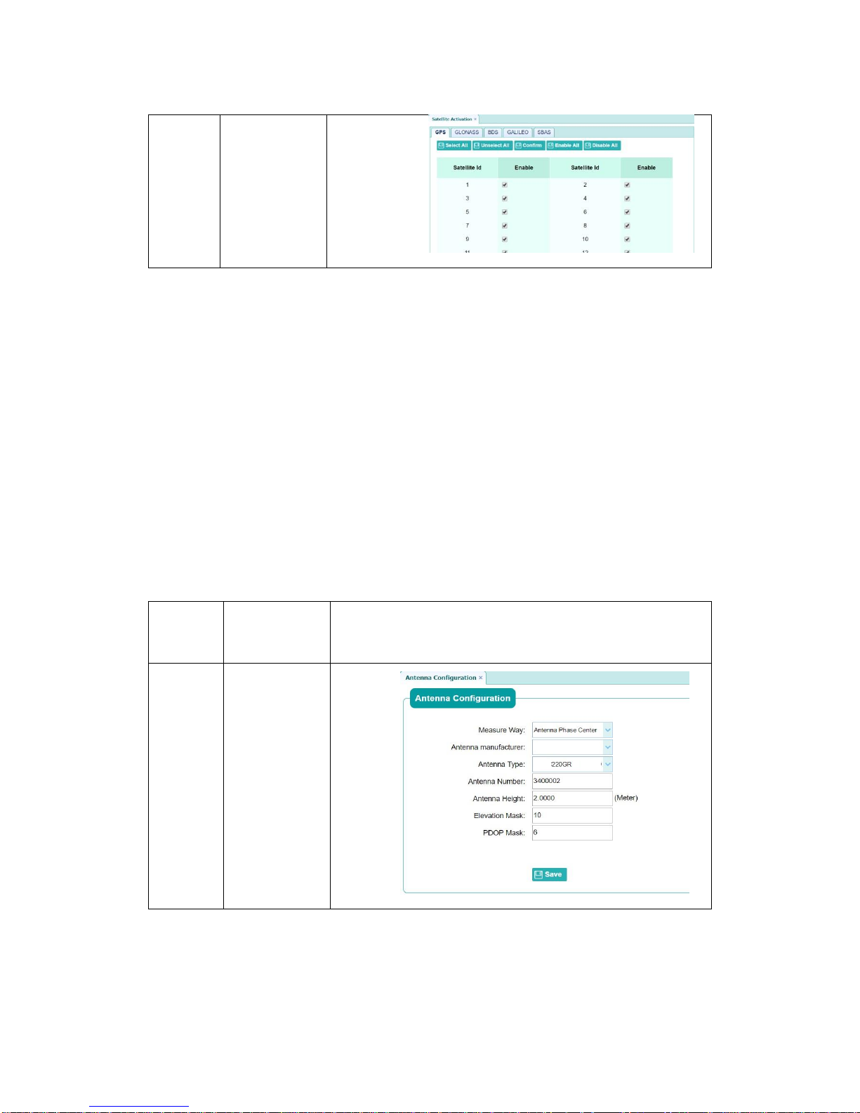
Satellite activation: Menu is used to enable/disable which satellites to track.
One can choose to enable/disable tracking of an entire constellation.
Receiver configuration
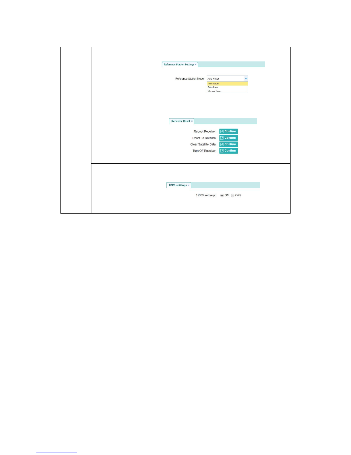
The receiver configuration menu supports Antenna configuration, Reference
station settings, Receiver reset and 1PPS settings as shown in Table 9.
Menu
Submenu
Information
Receiver
configur
ation
Antenna
configuration
Page 51
G7 Installation & Operation
Document PN 29010107 V1r1 - 51 -
Reference
station
settings
Receiver
reset
1PPS
settings
Table 9 – Receiver configuration options.
Antenna configuration: This page is used to make configure the antenna,
such as antenna type, elevation mask.
Reference station setting: Three kinds of modes are supported, namely, Auto
rover, Auto base and Manual base.
Receiver reset: This submenu supports four different settings for the receiver.
The reboot receiver means restart the receiver system without power off. The
reset to default means makes the receiver operate in default settings with
default configuration file. Clear satellite data is used to make the receiver
recapture the satellites and this operation needs several minutes to get enough
satellites to get the position information. Turn off receiver used to power off the
receiver from software side and cut the power off in hardware.
1PPS settings: This submenu is used to enable or disable the PPS signal
output. By default, the PPS signal is always enabled.
IO settings
The IO settings is used to enable the following settings as shown in Figure 22.
RTK client: to enable the G7 to receive correction from a CORS station
TCP client/server: To send or receive corrections from via TCP/IP protocol
Serial Port: Enables G7 to send NMEA messages to a PC serial port and set
Page 52
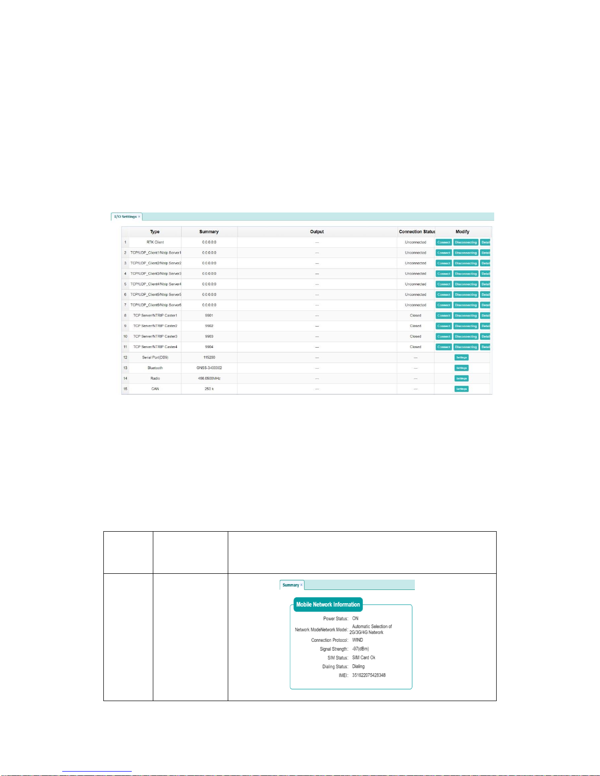
G7 Installation & Operation
Document PN 29010107 V1r1 - 52 -
data output rate
Bluetooth: Enables G7 to send NMEA messages to a PC or smartphone via
Bluetooth
Radio: configures the UHF radio parameter such as transmit power
CAN: Enables communicating NMEA data using the CAN protocol
More detail settings about this part will described in the Data Output Setup
section.
Figure 22 – IO settings.
Network set
The Network set (Settings) menu contains the Summary and Mobile network
setting as shown in Table 10.
Menu
Submenu
Information
Network
Set
Summary
Page 53
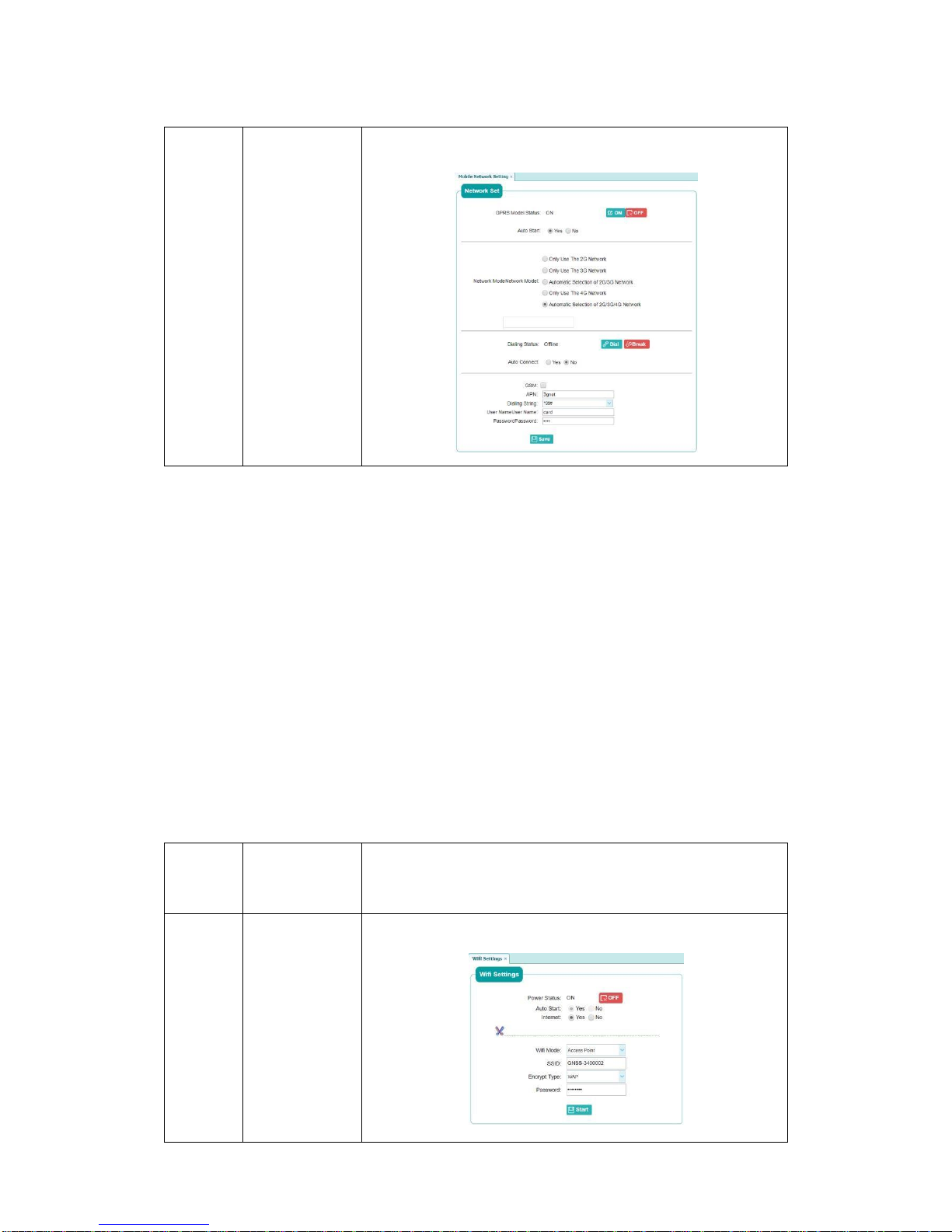
G7 Installation & Operation
Document PN 29010107 V1r1 - 53 -
Mobile
Network
Setting
Table 10 – Network setting menu.
Summary: This page shows the basic information about the network status for
the receiver, including power status, network model type, connection protocol
type, signal strength, SIM status, dialing status and IMEI number information.
Mobile network setting: This page is used for setting the mobile network work
mode, power status and dialing parameters.
Module setting
This menu is used to check the status and set the parameter for the modules
integrated in the G7 receiver including the WiFi, Bluetooth and UHF radio as
shown in Table 11.
Menu
Submenu
Information
Module
Setting
WiFi
Settings
Page 54
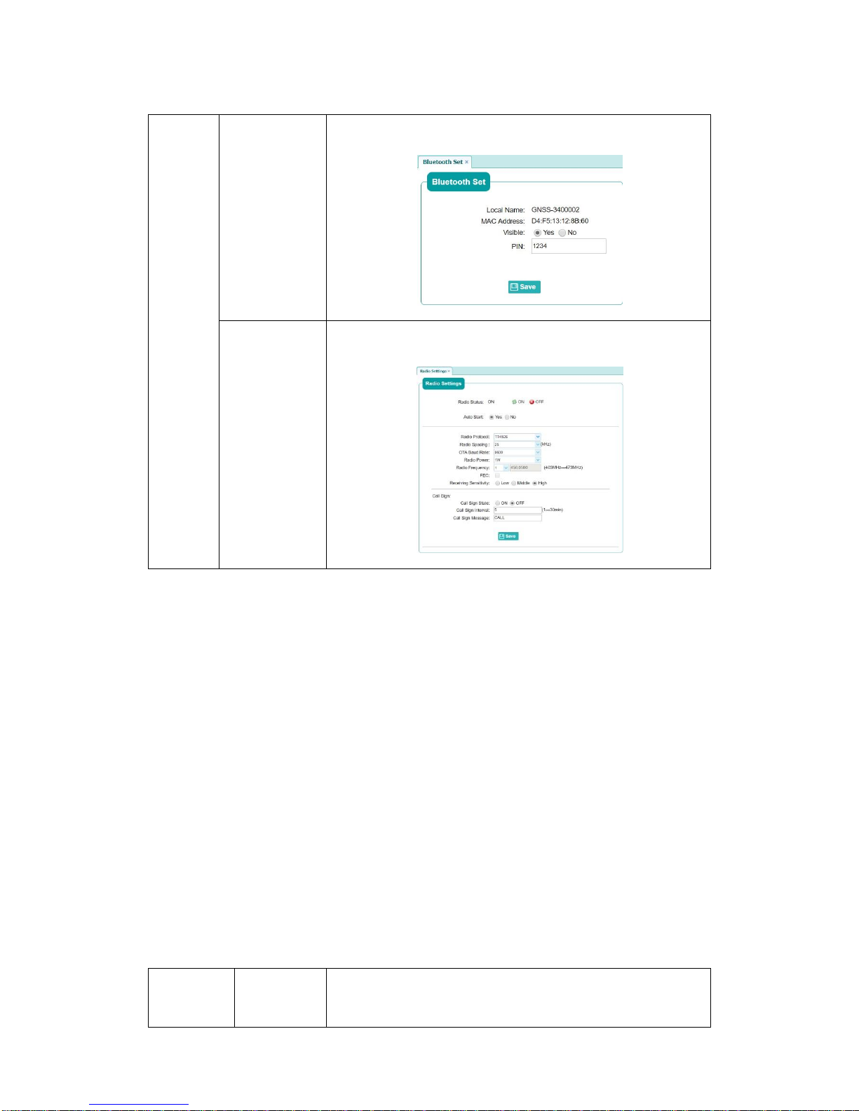
G7 Installation & Operation
Document PN 29010107 V1r1 - 54 -
Bluetooth
Set
Radio
setting
Table 11 – Module setting menu.
WiFi settings: The WiFi can be powered off in this page to reduce the power
consumption in some special application. Note that when you power off the WiFi
module, the webpage cannot work anymore until you restart the receiver.
The Encrypt type and Password can be changed in this page.
Bluetooth set: This page used to set the visible and PIN code for the Bluetooth.
The Local name and MAC address cannot be modified.
Radio setting: Power status can be set through this page. When you power off
the radio, the power consumption of the receiver will be reduced. Other radio
parameters can be set in this page.
Firmware
The firmware menu is shown in Table 12 showing the receiver firmware version,
hardware version, system log, user log, firmware update and receiver
registration.
Menu
Submenu
Information
Page 55

G7 Installation & Operation
Document PN 29010107 V1r1 - 55 -
Firmware
Firmware
info
The
hardware
version
System
log
User log
Firmware
update
GNSS
registration
Table 12 – Firmware setting menu.
Firmware info: The firmware info is important when troubleshooting. The
receiver’s firmware will be updated to the latest version during the
manufacturing process.
The hardware version: This part shows the receiver’s hardware version
information and the GNSS board information.
Page 56

G7 Installation & Operation
Document PN 29010107 V1r1 - 56 -
System log: This log file is designed in programming language for
troubleshooting and some useful running information will be record into this file.
If you meet a problem with the receiver, please click the download button to
download this log file and provide it to ComNav support team.
User log: This log file is designed to record running status information in user
language to make the user understand what happen in the receiver. The
information type can be selected in this page.
Firmware update: This submenu is designed for firmware update, when you
receive a new firmware for the receiver, please click the Browser button to
select the proper firmware file and clock the confirm button to make the update.
It takes about two or three minutes to install the update. For the latest firmware
resource, please consult your local ComNav dealer.
GNSS registration: A kind of registration mechanism is designed for the
receiver. If the registration code expires, you will lose control over the receiver
and data output will stopped. If your receiver expires, please provide the SN
number to ComNav support team to get help for registration.
Work mode setup
The G7 receiver supports several work modes such as Rover UHF, Rover
NTRIP and Base Int. UHF. The desired work mode can be setup from the PC
or the smartphone webpage.
This chapter will demonstrate the smart phone version of the webpage.
UHF Rover Settings
In this mode, the G7 is configured as a rover and receives correction data via
the UHF radio. Note that the setting of this mode using the computer is
different from the smartphone version.
Smartphone version
1. Connect your smartphone to the receiver’s WiFi and login to the webpage
2. Select the “RTK work mode” menu as shown in Figure 23. Click “Change work mode”
at the bottom of the page, and select “RTK work mode” as “Auto Rover”, “Data link” as
“Rover UHF”.
Page 57
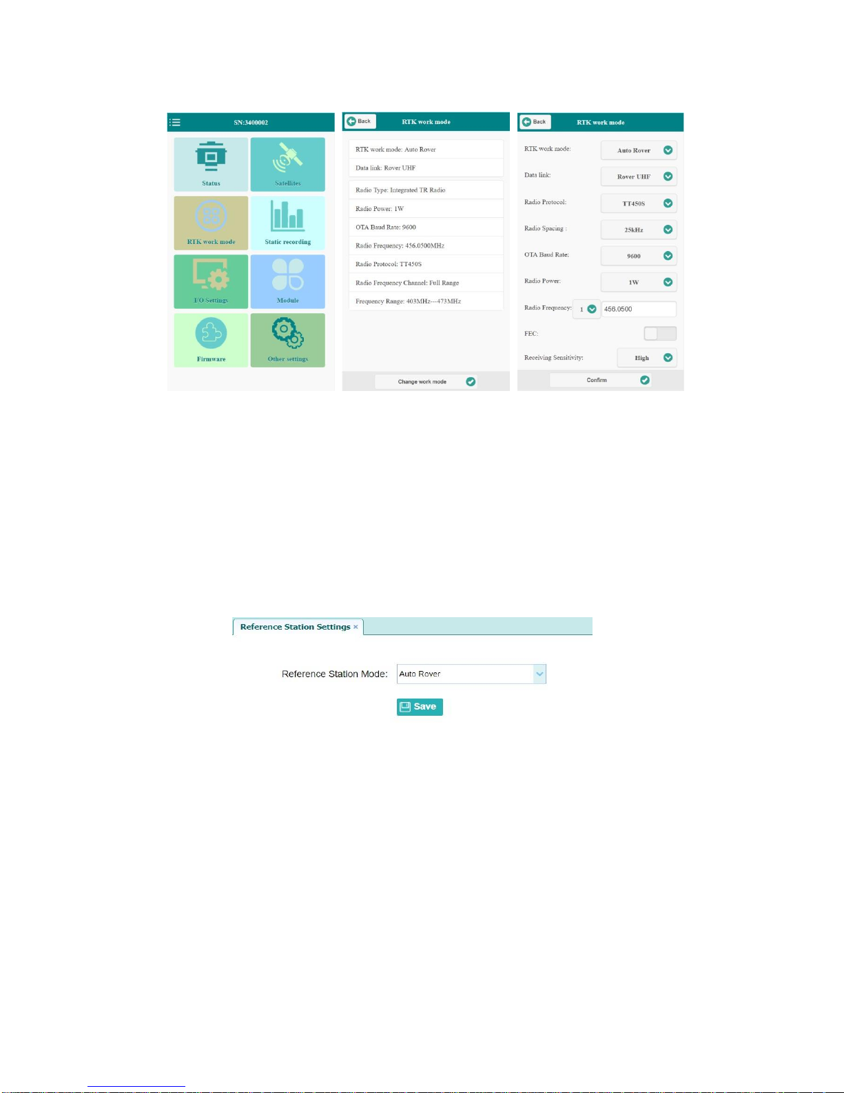
G7 Installation & Operation
Document PN 29010107 V1r1 - 57 -
Figure 23 – UHF Rover setting using smartphone.
Computer version
1. Connect your PC to the receiver’s WiFi and login to the webpage.
2. Go to “Receiver configuration” menu as shown in Figure 24, then click “Reference
station setting” submenu and choose “Auto rover”, then click “Save” button to make
the changes effective.
Figure 24 – Select Auto Rover.
3. Go to “Module setting” menu, then click “Radio setting”. If the radio is not powered on,
please power it on first, then choose the same configuration parameters as the base
station’s radio, and then click “Save” button to make the changes effective.
Make sure the base and rover radio settings are the same (see Fig. 25).
Page 58
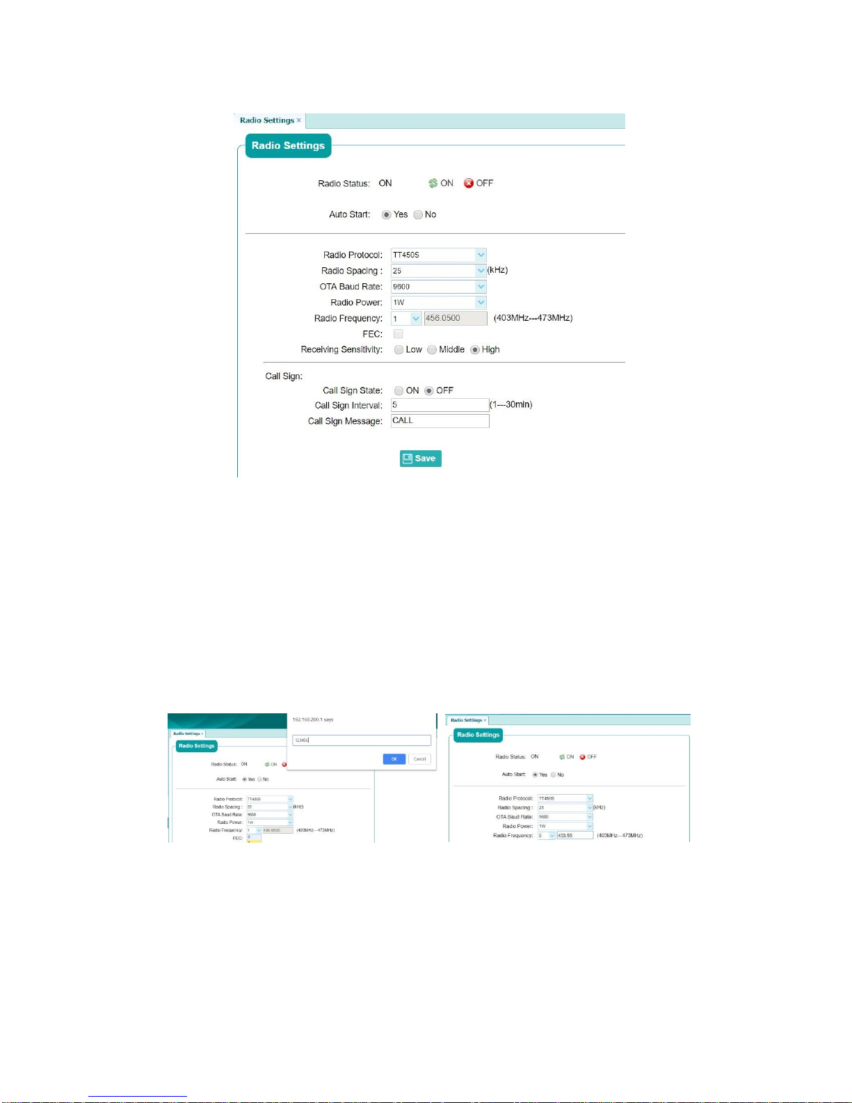
G7 Installation & Operation
Document PN 29010107 V1r1 - 58 -
Figure 25 – Set the UHF radio setting.
If you cannot choose a radio frequency that matches the base station from the
radio channel list, please select the radio channel as “0” and then a pop-up
window will appear in the browser as shown in Figure 26. Type the password
(by default it is 123456). If the password is correct, then you can type the radio
frequency to make it match with base station. Please note the radio frequency
range.
Figure 26 – UHF Radio setting.
For the receiver, the built-in radio type is Satel and radio frequency ranges
from 403MHz to 473Mhz. when you set the receiver work in this kind of mode,
please pay attention to the following points:
Page 59

G7 Installation & Operation
Document PN 29010107 V1r1 - 59 -
1. Make sure the base station is configured and the correction data is
transmitting by the UHF radio.
2. Check the radio antenna connection to the receiver, and make sure it is
installed properly.
3. Set and check the radio parameters in the webpage to make sure all of
the parameters you set for the receiver matches those set for the base
station’s radio settings.
4. Check the receiver’s LED status to monitor the correction data
transmission status.
5. Check the receiver’s built-in webpage for the position status.
Rover NTRIP/IP
The Rover NTRIP work mode has the receiver working in rover mode and uses
the built-in 4G network module to receive correction data from CORS server.
The available SIM card service and proper account for CORS service are
necessary for this work mode. Please install the SIM card properly before you
power on the receiver.
This section will be demonstrates using the smartphone and PC versions.
Smart phone version
1. Connect your smartphone to the receiver’s WiFi and login to the webpage.
2. Select the “Module” menu and click on the “GPRS” submenu, turn on the “GPRS
Model Status” if it is closed and “Auto Start” status bar also needs to be turned on.
The next step is to turn on the “Dialing Connect” and “Auto Connect”. Type proper
network parameter for “APN”, “Dialing String”, “User Name” and “Password”. After
that click “Confirm” button to make the settings effective.
Page 60
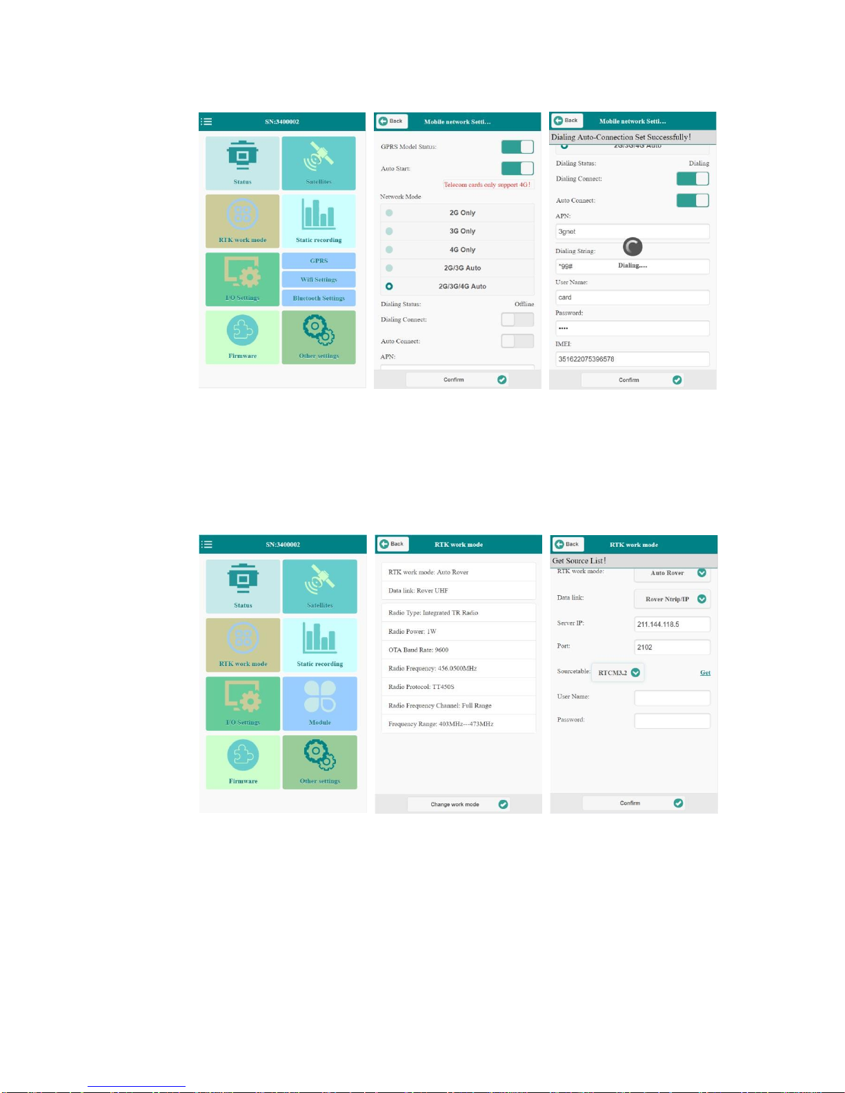
G7 Installation & Operation
Document PN 29010107 V1r1 - 60 -
Figure 27 – Connect the G7 to the cellular network.
3. Select the “RTK work mode” menu and click “Change work mode” at the bottom of
the page, select “RTK work mode” as “Auto Rover”, “Data link” as “Rover Ntrip/IP”.
Type IP address and port about the CORS service into the “Server IP” and “Port”
frame.
Figure 28 – RTK mode setup using NTRIP.
4. Get source table by click the “get” option and select the proper RTK correction data
format from the source table list. If there is nothing in the source table, please try it
again and check the network setting in “Module” menu. If it is working then you can
type the account and password in the “User Name” and “Password” fields. After that,
click “Confirm” button to make the changes effective.
Page 61
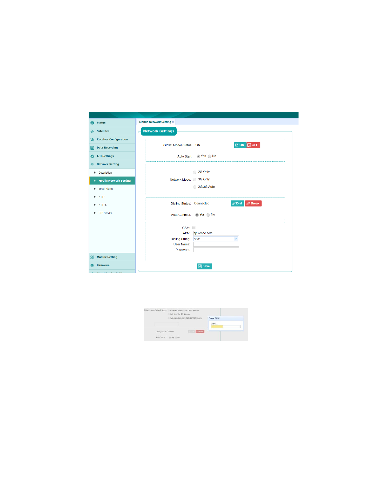
G7 Installation & Operation
Document PN 29010107 V1r1 - 61 -
Computer version
1. Connect the PC to the receiver’s WiFi and login to the webpage.
2. Select “Network setting” menu and go into the “Mobile Network Setting” submenu as
shown in Figure 29. Make sure the “GPRS Model Status” is on and “Auto Start” is
yes. Then set other parameters for the network model, such as “APN”, “Dialing
String”, “User Name” and “Password”
Figure 29 – Connect the G7 to the cellular network.
3. Click the “Dial” button to make the network module dial, then the “Dialing” window will
appear (See Figure 30), and the status “Dialing status” will change to ”connected”.
Figure 30 – Dialing.
4. Login to the CORS service with Ntrip protocol in the “IO settings” menu. Select the first
line named as “RTK Client” and click “Connect”. Choose the “Connection Protocol” as
“NTRIP” and type proper “Server IP” and “Port” into the field. Click “Get” button and
choose correct “Source List” in the drop-down box. Then input “User Name” and
“Password” as your service account and “Confirm” to make the changes effective.
Page 62
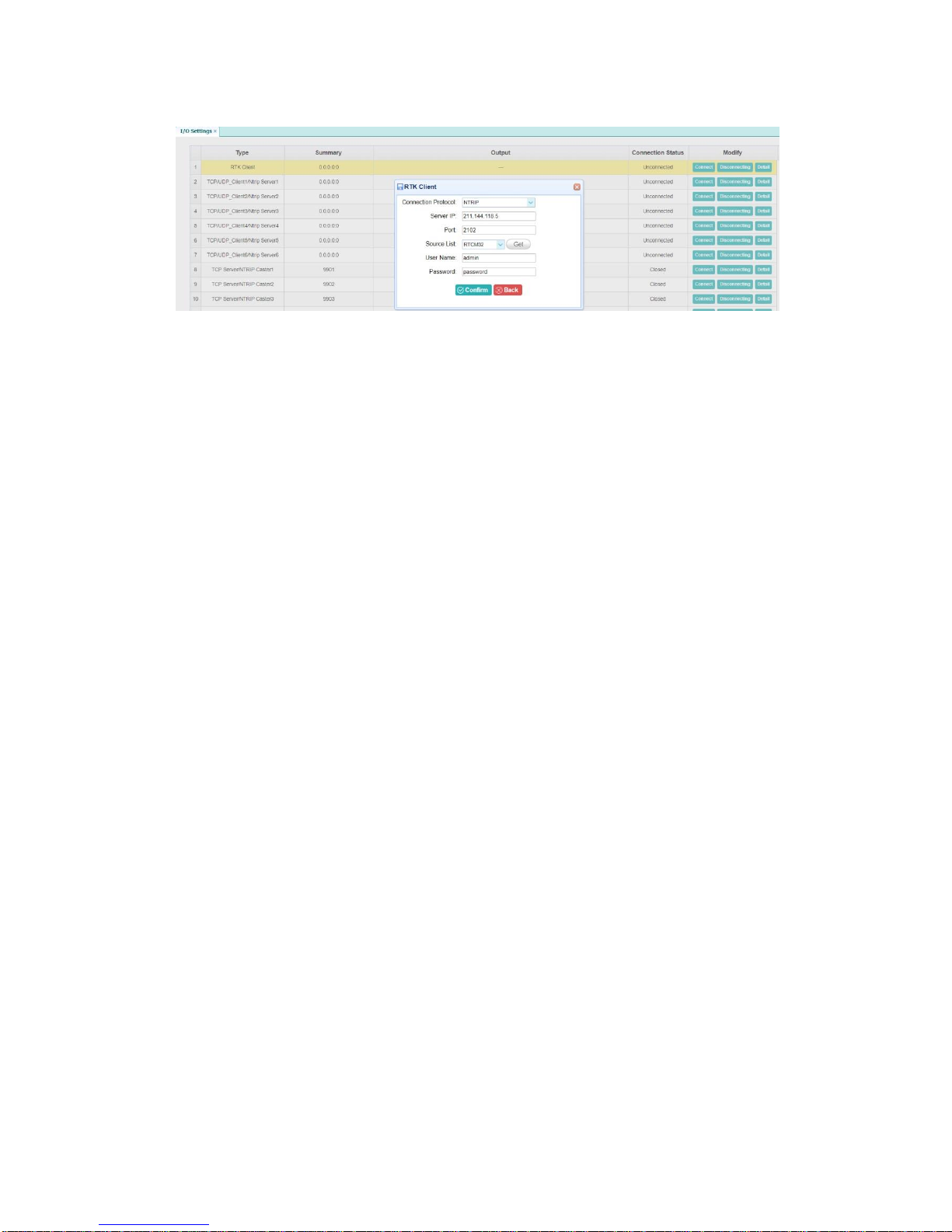
G7 Installation & Operation
Document PN 29010107 V1r1 - 62 -
Figure 31 – RTK client setting using NTRIP.
For this work mode, the receiver works with both both the SIM card and CORS
services to get better accuracy for the position. Please follow the following tips
to ensure optimal operation
1. Make sure the SIM card is in good condition and the network service is
not stopped by the supplier.
2. Make sure the 4G antenna is installed properly. Sometimes, because of
the weak signal, the dialing process will fail.
3. Make sure your CORS account and password is correct to get the RTK
service.
4. Choose the proper RTK source from the list after you got it.
5. Check the receiver’s LED status to monitor the correction data
transmission status when all the operations are done.
Base Int. UHF
This work mode is similar to the Rover UHF mode case, the major difference is
that the receiver works as a base station and correction data is sent by the
radio. This section will be illustrated using the smartphone and webpage
versions.
Smart phone version
1. Connect your smartphone to the receiver’s WiFi and login.
2. Select the “RTK work mode” menu into the setting page, click “Change work mode” at
the bottom of the page, select “RTK work mode” as “Auto Base” or “Manual Base”,
“Data link” as “Base Int. UHF”.
Note that there is a difference between “Auto Base” and “Manual Base”.
Page 63
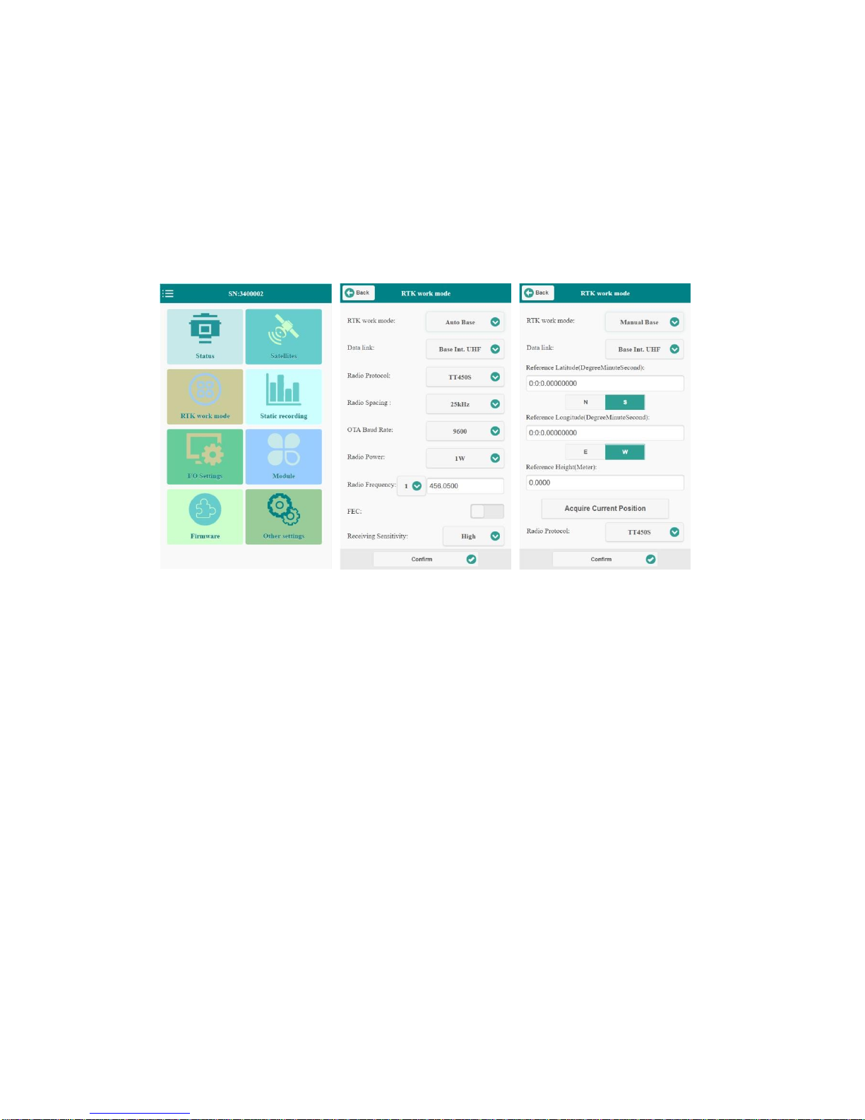
G7 Installation & Operation
Document PN 29010107 V1r1 - 63 -
In “Auto Base” mode, the receiver will broadcast correction data based on the
coordinate which is obtained through autonomous positioning automatically. It
is used when the receiver location is unknown beforehand.
In “Manual Base” mode, the receiver will broadcast correction data based on
the coordinate which is entered manually or “Acquired Current Position” by
clicking the button. It is used when the Base station is already known or
surveyed.
Figure 32 – Base Internal UHF radio setting.
3. Select the correction data format and finished by “Confirm” click.
Computer version
1. Connect the PC’s WiFi to the receiver and login.
2. Go to “Receiver configuration” menu, then click “Reference station setting” submenu
and choose “Auto Base” or “Manual Base” as shown in
Figure 33.
Page 64
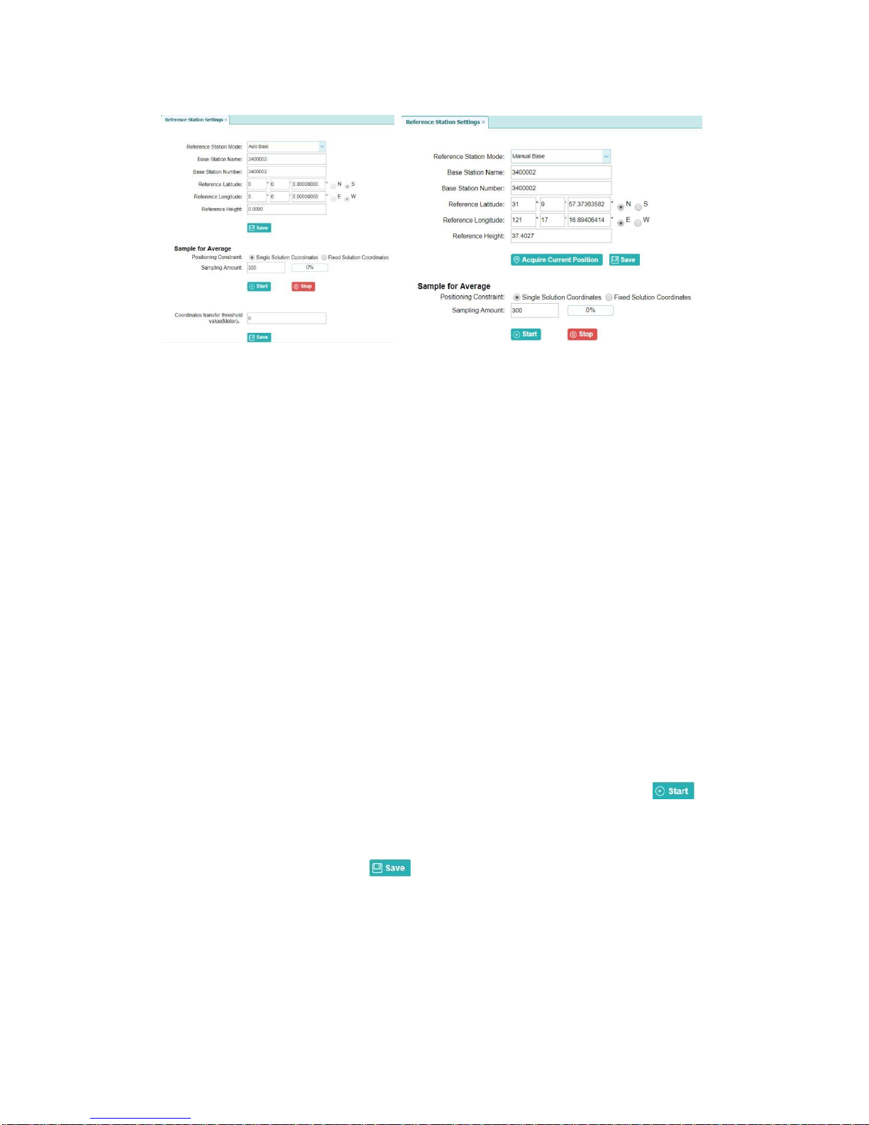
G7 Installation & Operation
Document PN 29010107 V1r1 - 64 -
Figure 33 – Auto base and manual base settings.
For the “Auto Base” mode, this mode is enabled by clicking the “Save” button,
the receiver will broadcast correction data based on the coordinate which is
obtained through autonomous positioning automatically.
For the “Manual Base” mode, the “Reference Latitude”, “Reference Longitude”
and “Reference Height” can be entered manually or use the “Acquire Current
Position” button to get the data automatically. After that click “Save” button to
make the changes effective.
For Sample for Average:
Users can determine the positioning limit and sampling amount. The positioning
limit falls into two types:
a) Single Solution Coordinates: Collect the coordinates of receiver obtained
through autonomous positioning.
b) Fixed Solution Coordinates: Only collect coordinates of receiver with a
fixed solution.
After the configuration of positioning limit and sampling amount, click to
carry out sampling and averaging → the progress bar will show the progress →
the result will be used as the coordinate of current position. If users need to
save the changes, please tap button.
3. Go to “Module setting” menu, then click “Radio setting”. The operation about radio
setting is same as in Rover UHF mode.
Page 65
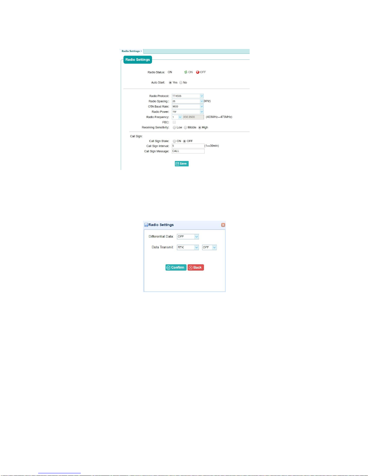
G7 Installation & Operation
Document PN 29010107 V1r1 - 65 -
Figure 34 – Radio settings.
4. Go into “IO settings” menu and select correction data format in “Differential Data”
drop-down box. “Confirm” to make the setting effective.
Figure 35 – Differential data settings using Radio.
Please pay attention on the following tips when you set the receiver work in this
mode.
1. Make sure that the radio antenna is installed properly with the antenna
installation guidance.
2. Take care of the latitude and longitude direction when you use the
manual base mode. Wrong direction will lead no correction data will be
sent.
3. Check the receiver’s LED status to monitor the correction data send
status when all the operations are finished.
Page 66

G7 Installation & Operation
Document PN 29010107 V1r1 - 66 -
Data output setup
The receiver is designed with a rich hardware interface and network
communication protocol to support common applications. This chapter provides
a detailed introduction of the communication ports.
Please read this chapter carefully when you set the data output first time for
your application.
Output Overview
The receiver works as a data source to support data output in different data and
connection protocols. The data protocol details is shown in Table 13.
Type
Subtype
Specification
Differential
Data
CMR
Only GPS correction message in CMR
standard;
Default output frequency as 1Hz;
CMR+
GPS and GLONASS correction message;
Default output frequency as 1Hz;
sCMRx
Full constellation message;
Default output frequency as
1Hz;
RTCM2.3
GPS and GLONASS correction message in
RTCMV2 standard;
Default output frequency as 1Hz;
RTCM3.0
GPS and GLONASS correction message
in
RTCMV3 standard;
Default output frequency as 1Hz;
Page 67

G7 Installation & Operation
Document PN 29010107 V1r1 - 67 -
RTCM3.2
Full constellation message in RTCMV3
format;
Default output frequency as 1Hz;
RTD
Default output frequency as 1Hz;
RT27
Raw satellite measurements;
Output frequency from 50hz to
60s;
Raw data
Ephemeris
Ephemeris
Ephemeris data for tracked satellites;
Output frequency as auto;
HRC
HRC
Self-defined data protocol for original
observation in compression format;
Output frequency from 1hz to 60s;
NMEA
Output
frequency from
10hz to 5s;
GPGGA
Time, position, and fix related data;
GPGSV
Number of SVs in view, PRN, elevation,
azimuth, and SNR;
GPRMC
Position, Velocity, and Time;
GPGLL
Position data: position fix, time of position
fix, and status;
GPVTG
Actual track made good and speed over
ground;
GPZDA
UTC day, month, and year, and local time
zone offset;
GPGST
Position error statistics;
Page 68

G7 Installation & Operation
GPGSA
Time, position, and fix related data;
GPHDT
Heading from True North;
GPROT
Rate of turn;
PTNL, VGK
Time, locator vector, type, and DOP values;
PTNL, VHD
Heading Information;
PTNL, GGK
Time, position, position type, and DOP
values;
PTNL, AVR
Time, yaw, tilt, range, mode, PDOP, and
number of SVs for Moving Baseline RTK;
PTNL, BPQ
Base station position and position quality
indicator;
PTNL, PJK
Time, position, position type, and DOP
values;
PTNL, PJT
Projection type;
Data transmit
RTK
Froward data from RTK;
Bluetooth
Froward data from Bluetooth;
Document PN 29010107 V1r1 - 68 -
Page 69

G7 Installation & Operation
Type
Protocol
type
Data protocol support
TCP/UDP client
TCP
All of data protocols support;
Server IP and Port needed;
UDP
All of data protocols support;
Server IP and Port needed;
Ntrip1.0
All of data protocols support;
Server IP, password, port and mount point
needed;
Radio
Froward data from Radio;
GPHCD
Self-defined data protocol for driving test
application;
Output frequency from 10hz to 60s;
GPHCD
KSXT
KSXT
Self-defined data protocol for driving test
application;
Output frequency from 1 to 10hz or from
2 to 60s;
Table 13 – Data protocol description and output rates.
The connection protocol is shown in Table 14.
Document PN 29010107 V1r1 - 69 -
Page 70

G7 Installation & Operation
Ntrip2.0
All of data protocols support;
Server IP, user name, password and port
needed;
TCP
server/NTRIP
caster
TCP
All of data protocols;
Default port number 9001;
NTRIP
All of data protocols;
User name, password, port and source list
needed enter;
Serial port
Baud rate
support 1200
to 460800
All of data protocols
Bluetooth
GNSS-
XXXXXXX
All of data protocols except data transmit;
Radio
(radio
frequency)
Differential data and data transmit;
Can
(250K)
All of data protocols except data transmit,
raw data and ephemeris data;
Transmission rate as 250k;
Setup webpage
The Figures 36 and 37 show the IO output setup and communication protocols respectively.
Enter proper information and select the data you require in the drop-down box, then
“Confirm” to make the changes effective.
Document PN 29010107 V1r1 - 70 -
Table 14 – Connection protocol.
Page 71
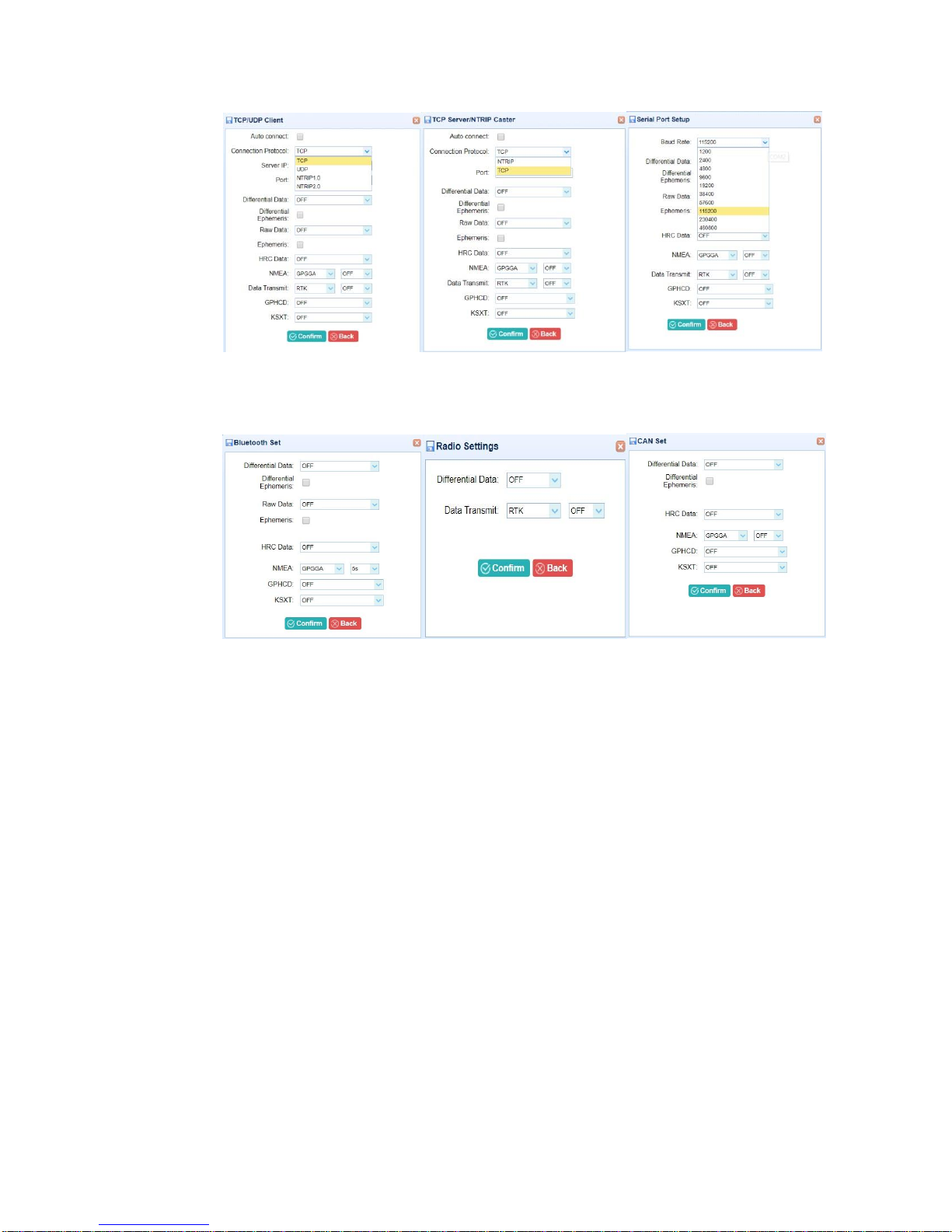
G7 Installation & Operation
Figure 36 – IO output setup for TCP/UDP client, TCP server/NTRIP caster, and serial port setup.
Figure 37 – IO setting for Bluetooth, radio and CAN.
Document PN 29010107 V1r1 - 71 -
Page 72

G7 Installation & Operation
Care & Maintenance
The receiver is a sophisticated electronic device for high precision measurement. It has been
designed to provide many years of reliable service with reasonable usage. The following
care and maintenance tips will help to ensure the longevity of the receiver, please pay
attention on this.
Transport
When transporting the product by rail, air or sea, always use the complete original ComNav
packaging, transport container and cardboard box, or its equivalent to protect against shock
and vibration.
Storage
Respect the temperature limits when storing the receiver. Please refer to chapter 5
Specification for information about temperature limits.
Warranty
The receiver has warranty service in the product life cycle and three more years beyond the
life cycle.
ComNav provides two years of free repair service after purchasing the product which was
under normal use and the fee service will last until three years of suspension.
If the receiver in your side become damaged and can’t work anymore in any way, after
connecting with support team in ComNav, please follow the following steps to start the repair
service:
1. Uninstall the receiver only from your application;
2. Package the receiver with suitable packaging material;
3. Return it to an authorized ComNav dealer;
4. After repairment, we will return it the original way;
Document PN 29010107 V1r1 - 72 -
Page 73
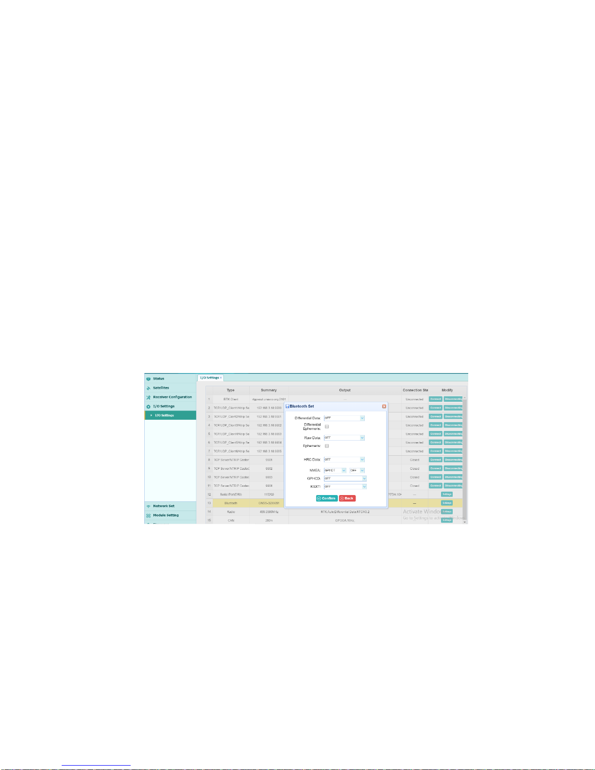
G7 Installation & Operation
Appendices
Appendix 1
Logging Data
This chapter outlines how to log data from the G7. This operation can be performed by
streaming the data from the G7 to a PC via Bluetooth or serial cable.
The steps to stream and save data to a PC is as follows:
Configure the G7 to output NMEA messages via Bluetooth or serial communication
1. Power up the G7, and make sure it is operating normally.
2. Connect your PC’s WiFi to the G7 WiFi and log in
3. To connect via Bluetooth, go to IO setting as shown in Figure 38 below, then select Bluetooth and set the
NMEA messages desired. By default, the NMEA messages are turned off. Select the NMEA message
and click on confirm to save the changes.
4. To connect via serial cable (A_RS232) go to IO setting as shown in Figure 39 below, then select Serial
port and set the NMEA messages desired. By default, the NMEA messages are turned off. Select the
NMEA message and the baud rate (in the Figure 39 the GPGGA sentence is set to an update rate of 10
Hz and the baud rate is set to 115200), Click on confirm to save the changes.
Document PN 29010107 V1r1 - 73 -
Figure 38 – Set Bluetooth NMEA messages.
Page 74
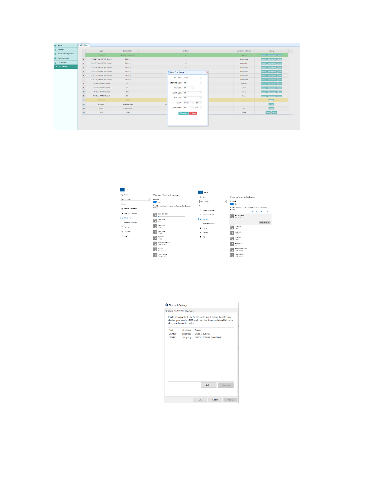
G7 Installation & Operation
Figure 39 – Set Serial port messages.
Stream and log data via Bluetooth
1. Connect PC’s Bluetooth to G7 Bluetooth (see Figure 40).
Figure 40 – Connect to G7 via Bluetooth.
2. Once connected find the COM port associated with the G7 Bluetooth. Go to “Bluetooth settings”, and
under “COM ports” find G7’s outgoing com port as shown in Figure 41. The desired port number is
shown to be COM 23.
Figure 41 – Bluetooth COM port.
Document PN 29010107 V1r1 - 74 -
Page 75

G7 Installation & Operation
3. Open a serial Terminal program. In this guide, Tera Term is used. Launch Tera Term and select the
desired COM port (in this case it is COM 23) – See Figure 42.
Figure 42 – Select desired COM port for Bluetooth connection.
4. The sentences will appear at the terminal as shown in Figure 43.
Figure 43 – Tera Term terminal showing NMEA sentences.
5. To save data, go to File Log, and select a file name to log the data into as shown in Figure 44.
Document PN 29010107 V1r1 - 75 -
Page 76
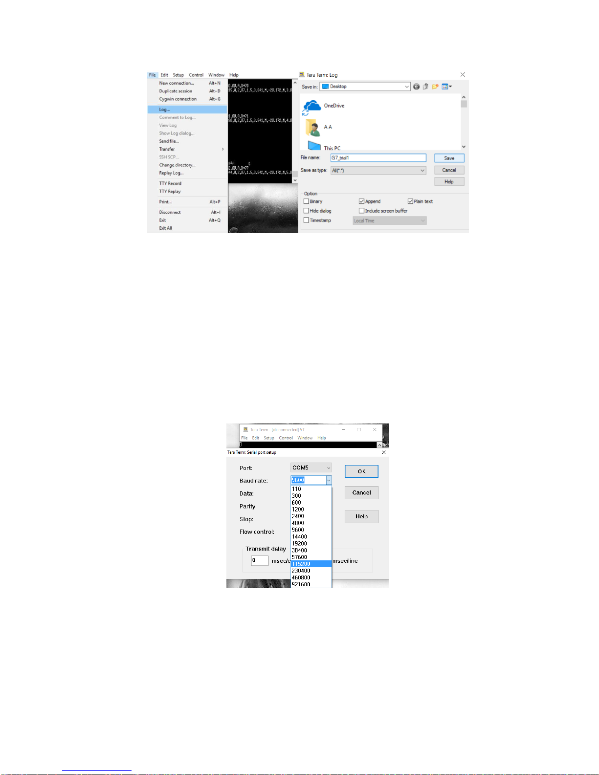
G7 Installation & Operation
Figure 44 – Data logging using Tera Term.
Stream and log data via Serial cable
1. Connect the A_RS232 port of the aviation plug (See Figure 5) to a PC, and
determine the COM port.
2. Launch Tera Term, and connect to the desired COM port (see Figure 42)
3. Set the baud rate to match that of the G7 baud rate. Go to Setup Serial port as
shown in Figure 45.
4. See Figures 43 and 44 above to log data.
Document PN 29010107 V1r1 - 76 -
Figure 45 – Baud rate setup.
Page 77

G7 Installation & Operation
Parameter
Specification
Real time
kinematic
Accuracy
Horizontal
8 mm + 1 ppm RMS
Vertical
15 mm + 1 ppm RMS
Autonomous
Accuracy
Horizontal
1.00 m RMS
Vertical
1.50 m RMS
SBAS Accuracy
Horizontal
0.50 m RMS
Vertical
0.85 m RMS
Code differential
Accuracy
Horizontal
0.25 m + 1 ppm RMS
Vertical
0.50 m + 1 ppm RMS
Time accuracy
20 ns RMS
Specification
This chapter describes the specifications of the G7 GNSS heading receiver. Specifications
are subject to change without notice.
G7 receiver specification
The key specifications are shown in Table 15 below, describing the positioning accuracy,
signal tracking and output data rates.
Document PN 29010107 V1r1 - 77 -
Page 78

G7 Installation & Operation
Heading accuracy
< 0.8˚ rms @ 0.3 m antenna separation
< 0.3˚ rms @ 0.5 m antenna separation
< 0.15˚ rms @ 1.0 m antenna separation
< 0.08˚ rms @ 2.0 m antenna separation
< 0.02˚ rms @ 5.0 m antenna separation
< 0.01˚ rms @10.0 m antenna separation
Channels
336
Positioning and vector both
Signal Tracking
GPS
L1 C/A, L2E, L2C, L5
GLONASS
L1 C/A, L2 C/A, L3 CDMA
BeiDou
B1, B2, B3
Galileo
E1, E5A, E5B, E5AltBOC, E6
IRNSS
L5
QZSS
L1 C/A, L1 SAIF, L2C, L5, LEX
SBAS (Position
Antenna Only)
L1 C/A L5
MSS L-Band
(Position
Antenna Only)
OmniSTAR, Trimble RTX
(optional)
Time to first fix
Cold start
<45 s
Worm start
<30 s
Document PN 29010107 V1r1 - 78 -
Page 79
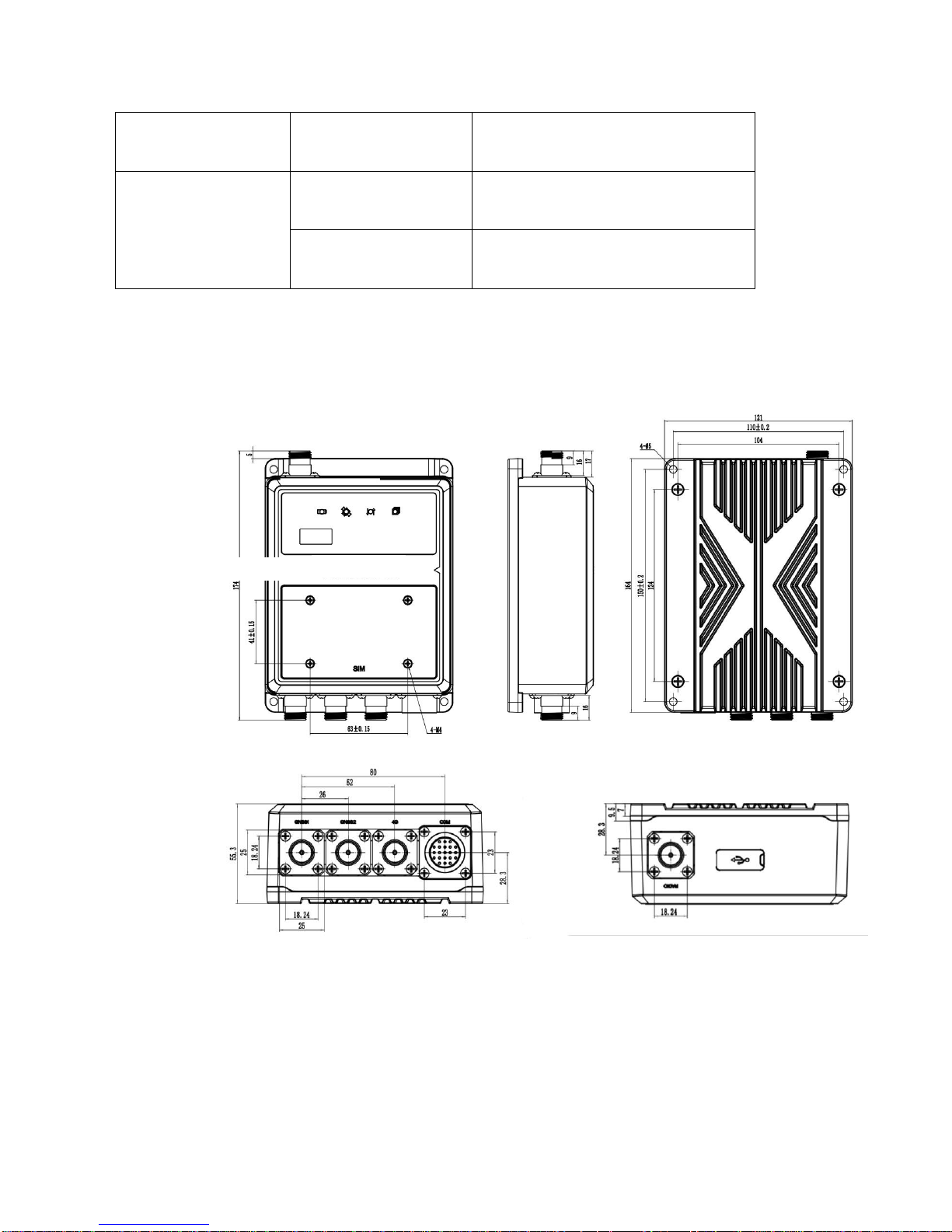
G7 Installation & Operation
Signal reacquisition
<2 s
Data rates
Measurements
20Hz Standard 50hz optional
Position
20Hz Standard 50hz optional
Table 15 – Receiver performance specification.
Mechanical
The receiver mechanical specifications are shown in Figure 46.
Document PN 29010107 V1r1 - 79 -
Figure 46 – Mechanical specification.
Page 80

G7 Installation & Operation
Feature
Specification
Size
170.0 x 120 x 57 mm (6.7 x 4.7 x 2.3 in)
Weight
1.2 kg (42 oz)
Temperature
Operating
-40°C to +75°C (-40°F to +167°F)
Storage
-55°C to +85°C (-67°F to +185°F)
Humidity
100% condensation
Ingress
protection
IP67, Waterproof and dust proof
Shock
Designed to survive a 1 m pole drop
Voltage
12V DC recommended, 9~36V DC supported
Power
consumption
4.3 W (depending on user settings)
WiFi
802.11 b/g/n, access point mode
Bluetooth®
V4.1
UHF radio
Frequency range
403 MHz to 473 MHz
Electrical and environmental
The Table 16 below shows the electrical and environmental specifications about the
receiver.
Document PN 29010107 V1r1 - 80 -
Page 81

G7 Installation & Operation
Transmit power
0.5 W to 2 W
Protocol
ComNav, Trimble, Pacific
Crest
Range
5 km optical conditions
Network modem
Internal 4G modem
LTE: B1, B3, B7, B8, B20
DCS1800, GSM900
Data Storage
32 GB high-speed memory
Port Type
Specification
A-RS232
Electrical format: RS232
Data rates: 460800 bps max
B-RS232
Electrical format: RS232
Data rates: 460800 bps max
CAN
Electrical format: RS232
Data rates: 250 kbps default
CAN Bus throughput is determined by slowest
device on the bus
Table 16 – Electrical and environmental properties.
Data communication
The data communication information is shown in Table 17.
Document PN 29010107 V1r1 - 81 -
Page 82

G7 Installation & Operation
SMA
PPS signal port as SMA format
Pulse wide: about 8 microseconds
Electrical Level: 3.3 V TTL
DC Jack
Power supply port
12V DC recommended, and 9~36V DC support
RJ45
Network connect port, used for GNSS board built-in
webpage login
Issue
Possible
Reason
Solution
The receiver does
not turn on.
Power is too
low.
Check the charge on the external
battery and, if applicable, check the
fuse.
External
power is not
properly
connected.
Check that the power connector is
seated correctly and that the cable is
secured to the receiver.
Check for broken or bent pins in the
connector.
Table 17 – G7 Data communication.
Troubleshooting
Use this chapter to identify and solve common problems that may occur during the use of
the receiver (See Table 18). Please read this section before you contact ComNav Technical
Support. This section describes some possible receiver issues, possible causes, and how
to solve them.
Document PN 29010107 V1r1 - 82 -
Page 83

G7 Installation & Operation
Faulty power
cable.
Check that you are using the correct
cable for the connection between power
port and power supply.
Check that the correct external power
supply is connected to a particular
power port.
Check pinouts with a multimeter to
ensure internal wiring is intact.
The receiver is
not responding.
Receiver needs
a soft reset.
Turn off the receiver and then turn it
back on again.
The receiver is
not receiving
satellite signals
The GNSS
antenna cable
is loose.
Make sure that the GNSS antenna cable
is tightly seated in the antenna
connector on the GNSS antenna.
The cable is
damaged
Check the cable for any signs of
damage. A damaged cable can inhibit
signal detection from the antenna at the
receiver.
The GNSS
antenna is not
in clear line of
sight to the sky.
Make sure that the GNSS antenna is
located with a clear view of the sky.
Restart the receiver as a last resort (turn
off and then turn it on again).
Document PN 29010107 V1r1 - 83 -
Table 18 – Troubleshoot the G7.
Page 84

G7 Installation & Operation
Glossary
Document PN 29010107 V1r1 - 84 -
Page 85

G7 Installation & Operation
1PPS
Pulse-per-second. Used in hardware timing. A pulse is generated
in conjunction with a time stamp. This defines the instant when
the time stamp is applicable.
base station
Also called heading station. A base station in construction, is a
receiver placed at a known point on a jobsite that tracks the same
satellites as an RTK rover and provides a real-time differential
correction message stream through radio to the rover, to obtain
centimeter level positions on a continuous real-time basis. A base
station can also be a part of a virtual heading station network, or a
location at which GPS observations are collected over a period of
time, for subsequent postprocessing to obtain the most accurate
position for the location.
carrier
A radio wave having at least one characteristic (such as frequency,
amplitude, or phase) that can be varied from a known heading value
by modulation.
carrier
frequency
The frequency of the unmodulated fundamental output of a radio
transmitter. The GPS L1 carrier frequency is 1575.42 MHz.
carrier phase
The time taken for the L1 or L2 carrier signal generated by the
satellite to reach the GPS receiver. Measuring the number of carrier
waves between the satellite and receiver is a very accurate method
of calculating the distance between them.
CMR
CMR+
Compact Measurement Record. A real-time message format
developed by Trimble for broadcasting corrections to other Trimble
mainboard receivers. CMR is a more efficient alternative to RTCM.
DGPS
See real-time differential GPS.
differential
correction
Differential correction is the process of correcting GPS data
collected on a rover with data collected simultaneously at a base
station. Because the base station is on a known location, any errors
in data collected at the base station can be measured, and the
necessary corrections applied to the rover data.
Differential correction can be done in real-time, or after the data has
been collected by postprocessing.
Glossary
Document PN 29010107 V1r1 - 85 -
Page 86

G7 Installation & Operation
Differential GPS
See real-time differential GPS.
DOP
Dilution of Precision. A measure of the quality of GPS positions,
based on the geometry of the satellites used to compute the
positions. When satellites are widely spaced relative to each other,
the DOP value is lower, and position accuracy is greater. When
satellites are close together in the sky, the DOP is higher and GPS
positions may contain a greater level of error.
PDOP (Position DOP) indicates the three-dimensional geometry of
the satellites. Other DOP values include HDOP (Horizontal DOP)
and VDOP (Vertical DOP), which indicate the accuracy of horizontal
measurements (latitude and longitude) and vertical measurements
respectively. PDOP is related to HDOP and VDOP as follows:
PDOP² = HDOP² + VDOP²
dual-frequency
GPS
A type of receiver that uses both L1 and L2 signals from GPS
satellites. A dual-frequency receiver can compute more precise
position fixes over longer distances and under more adverse
conditions because it compensates for ionospheric delays.
EGNOS
European Geostationary Navigation Overlay Service. A satellite
based augmentation system (SBAS) that provides a free-to-air
differential correction service for GPS.
EGNOS is the European equivalent of WAAS, which is available in
the United States.
elevation mask
The angle below which the receiver will not track satellites. Normally
set to 10 degrees to avoid interference problems caused by
buildings and trees, and multipath errors.
ephemeris /
ephemerides
A list of predicted (accurate) positions or locations of satellites as a
function of time. A set of numerical parameters that can be used to
determine a satellite’s position.
Available as broadcast ephemeris or as postprocessed precise
ephemeris.
epoch
The measurement interval of a GPS receiver. The epoch varies
according to the measurement type: for real-time measurement it
is set at one second; for postprocessed measurement it can be set
to a rate of between one second and one minute. For example, if
data is measured every 15 seconds, loading data using 30-second
epochs means loading every alternate measurement.
Document PN 29010107 V1r1 - 86 -
Page 87

G7 Installation & Operation
firmware
The program inside the receiver that controls receiver operations
and hardware.
GLONASS
Global Orbiting Navigation Satellite System. GLONASS is a Soviet
space-based navigation system comparable to the American GPS
system. The operational system consists of 21 operational and 3
non-operational satellites in 3 orbit planes.
GNSS
Global Navigation Satellite System.
GSOF
General Serial Output Format. A Trimble proprietary message
format.
HDOP
Horizontal Dilution of Precision. HDOP is a DOP value that indicates
the accuracy of horizontal measurements. Other DOP values
include VDOP (vertical DOP) and PDOP (Position DOP).
Using a maximum HDOP is ideal for situations where vertical
precision is not particularly important, and your position yield would
be decreased by the vertical component of the PDOP ( for example,
if you are collecting data under canopy).
L1
The primary L-band carrier used by GPS satellites to transmit
satellite data.
L2
The secondary L-band carrier used by GPS satellites to transmit
satellite data.
L5
The third L-band carrier used by GPS satellites to transmit satellite
data. L5 will provide a higher power level than the other carriers. As
a result, acquiring and tracking weak signals will be easier.
MSAS
MTSAT Satellite-Based Augmentation System. A satellite-based
augmentation system (SBAS) that provides a free-to-air differential
correction service for GPS. MSAS is the Japanese equivalent of
WAAS, which is available in the United States.
multifrequency
GPS
A type of receiver that uses multiple carrier phase measurements
(L1, L2, and L5) from different satellite frequencies.
multipath
Interference, similar to ghosts on a television screen that occurs
when GPS signals arrive at an antenna having traversed different
paths. The signal traversing the longer path yields a larger
pseudorange estimate and increases the error. Multiple paths can
arise from reflections off the ground or off structures near the
antenna.
Document PN 29010107 V1r1 - 87 -
Page 88

G7 Installation & Operation
NMEA
National Marine Electronics Association. NMEA 0183 defines the
standard for interfacing marine electronic navigational devices. This
standard defines a number of 'strings' referred to as NMEA strings
that contain navigational details such as positions. Most ComNav
GPS receivers can output positions as NMEA strings.
PDOP
Position Dilution of Precision. PDOP is a DOP value that indicates
the accuracy of three-dimensional measurements. Other DOP
values include VDOP (vertical DOP) and HDOP (Horizontal Dilution
of Precision).
Using a maximum PDOP value is ideal for situations where both
vertical and horizontal precision are important.
postprocessing
Postprocessing is the processing of satellite data after it has been
collected, in order to eliminate error. This involves using computer
software to compare data from the rover with data collected at the
base station.
real-time
differential
GPS
Also known as real-time differential correction or DGPS. Real-time
differential GPS is the process of correcting GPS data as you collect
it. Corrections are calculated at a base station and then sent to the
receiver through a radio link. As the rover receives the position it
applies the corrections to give you a very accurate position in the
field.
Most real-time differential correction methods apply corrections to
code phase positions. RTK uses carrier phase measurements.
While DGPS is a generic term, its common interpretation is that it
entails the use of single-frequency code phase data sent from a
GPS base station to a rover GPS receiver to provide sub-meter
position accuracy. The rover receiver can be at a long range
(greater than 100 km (62 miles)) from the base station.
heading station
See base station
rover
A rover is any mobile GPS receiver that is used to collect or update
data in the field, typically at an unknown location.
Document PN 29010107 V1r1 - 88 -
Page 89

G7 Installation & Operation
RTCM
Radio Technical Commission for Maritime Services. A commission
established to define a differential data link for the real-time
differential correction of roving GPS receivers. There are three
versions of RTCM correction messages. All ComNav GPS receivers
use Version 2 protocol for single-frequency DGPS type corrections.
Carrier phase corrections are available on Version 2, or on the
newer Version 3 RTCM protocol, which is available on certain
ComNav dual-frequency receivers. The Version 3 RTCM protocol is
more compact but is not as widely supported as Version 2.
RTK
Real-time kinematic. A real-time differential GPS method that uses
carrier phase measurements for greater accuracy.
SBAS
Satellite-Based Augmentation System. SBAS is based on
differential GPS but applies to wide area (WAAS/EGNOS and
MSAS) networks of heading stations. Corrections and additional
information are broadcast via geostationary satellites.
signal-to-noise
ratio
SNR. The signal strength of a satellite is a measure of the
information content of the signal, relative to the signal’s noise. The
typical SNR of a satellite at 30° elevation is between 47 and 50
dBHz. The quality of a GPS position is degraded if the SNR of one
or more satellites in the constellation falls below 39.
skyplot
The satellite skyplot confirms reception of a differentially corrected
GPS signal and displays the number of satellites tracked by the GPS
receiver, as well as their relative positions.
SNR
See signal-to-noise ratio
UTC
Universal Time Coordinated. A time standard based on local solar
mean time at the Greenwich meridian.
VRS
Virtual Heading Station. A VRS system consists of GNSS hardware,
software, and communication links. It uses data from a network of
heading stations to provide corrections to each rover that are more
accurate than corrections from a single base station.
To start using VRS corrections, the rover sends its position to the
VRS server. The VRS server uses the heading station data to model
systematic errors (such as ionospheric noise) at the rover position.
It then sends RTCM or CMR correction messages back to the rover.
Document PN 29010107 V1r1 - 89 -
Page 90

G7 Installation & Operation
WAAS
Wide Area Augmentation System. WAAS was established by the
Federal Aviation Administration (FAA) for flight and approach
navigation for civil aviation. WAAS improves the accuracy and
availability of the basic GPS signals over its coverage area, which
includes the continental United States and outlying parts of Canada
and Mexico.
The WAAS system provides correction data for visible satellites.
Corrections are computed from ground station observations and
then uploaded to two geostationary satellites. This data is then
broadcast on the L1 frequency and is tracked using a channel on
the GPS receiver, exactly like a GPS satellite.
Use WAAS when other correction sources are unavailable, to obtain
greater accuracy than autonomous positions. For more information
on WAAS, refer to the FAA website at http://gps.faa.gov. The
EGNOS service is the European equivalent and MSAS is the
Japanese equivalent of WAAS.
Document PN 29010107 V1r1 - 90 -
Page 91

Error! Unknown document property name. G7 Installation & Operation
CE Compliance
This product has been tested and is in compliance with the Navigation requirements of
Marine Equipment Directive 96/98/EC and the last modification by Directive 2012/32/EU, and
therefore bears the CE-marking.
It has been tested according to the applicable sections outlined under:
ISO 22090-3 Ed. 1.0, 2004 incl. Corr. 1, 2005
IEC 60945 Ed. 4.0, 2002 incl. Corr. 1, 2008
IEC 62288 Ed.1.0, 2008
IEC 61162-1 Ed. 4.0, 2010
IEC 61162-2 Ed. 1.0, 1998
Document PN 29010107 V1r1 - 91 -
Page 92

Error! Unknown document property name. G7 Installation & Operation
Firmware License Agreement
COMNAV MARINE LTD. FIRMWARE LICENSE
AGREEMENT
BEFORE USING LICENSED FIRMWARE, CAREFULLY READ THIS LICENSE AGREEMENT.
This document is an agreement (“Agreement”) between the end user (the “Licensee”) and ComNav Marine Ltd, (“ComNav”) that sets forth
the Licensee’s rights and obligations with respect to the ComNav software and firmware, including without limitation any accompanying
documentation, hardware or media (the “Firmware”) and prevails over any additional, conflicting or inconsistent terms and conditions
appearing on any purchase order or other document submitted by the Licensee. “Affiliate” means any person, partnership, corporation,
limited liability company, other form of enterprise that directly or indirectly through one or more intermediaries, controls, or is controlled by,
or is under common control with the party specified. In this Agreement, any ComNav Product that has Firmware embedded in it or included
with it at the time of sale to the Licensee shall be referred to as the “Product”. This Agreement constitutes the entire understanding between
the parties, with respect to the subject matter of this Agreement.
BY USING OR OTHERWISE ENABLING THE PRODUCT, THE LICENSEE REPRESENTS IT IS AUTHORIZED TO ACCEPT THESE
TERMS ON BEHALF OF THE END USER (IF THE END USER IS AN ENTITY ON WHOSE BEHALF THE LICENSEE IS AUTHORIZED
TO ACT, THE LICENSEE SHALL BE DEEMED TO REFER TO THE END USER) AND THAT THE LICENSEE AGREES TO BE BOUND
BY THE TERMS OF THIS AGREEMENT, WHICH INCLUDES, AMONG OTHER PROVISIONS, THE LICENSE, THE DISCLAIMER OF
WARRANTY AND THE LIMITATION OF LIABILITY. IF THE LICENSEE DOES NOT AGREE TO THE TERMS OF THIS AGREEMENT
OR ARE NOT AUTHORIZED TO ENTER INTO THIS AGREEMENT, COMNAV IS UNWILLING TO LICENSE THE FIRMWARE TO THE
LICENSEE AND THE LICENSEE AGREES THAT THE LICENSEE IS NOT AUTHORIZED TO ENABLE OR USE SAID LICENSED
FIRMWARE.
The Licensee and ComNav agree as follows:
1. LICENSE. The Licensee has the non-exclusive and non-transferable license to enable the Firmware on each Product that the
Licensee has purchased subject to the terms and conditions of this Agreement.
2. RESTRICTIONS. Except as otherwise authorized in writing by ComNav, the Licensee may not, nor may the Licensee permit
any third party to:
a. Reverse engineer, decompile, disassemble or modify the Firmware, in whole or in part, except to the extent
expressly permitted by applicable law and to the extent the parties shall not be permitted by that applicable law, such
rights are expressly excluded.
b. Incorporate the Firmware in whole or in part, in any other product or create derivative works based on the Firmware,
in whole or in part.
c. Publish, disclose, copy reproduce or transmit the Firmware, in whole or in part.
d. Assign, sell, license, sublicense, rent, lease, encumber by way of security interest, pledge or otherwise transfer the
Firmware, in whole or in part.
e. Remove any copyright, trademark, proprietary rights, disclaimer or warning notice included on or embedded in any
part of the Firmware
3. UPDATES. At ComNav's discretion ComNav may make Updates available to the Licensee. An update ("Update") means any
update to the Firmware that is made available to the Licensee including error corrections, enhancements and other
modifications. All Updates that the Licensee downloads, installs or uses shall be deemed to be Firmware and subject to this
Agreement. ComNav reserves the right to modify the Product without any obligation to notify, supply or install any
improvements or alterations to existing Firmware.
4. OWNERSHIP. ComNav owns all rights, title and interest in and to the Firmware and related materials, including all intellectual
property rights. The Firmware is licensed to the Licensee, not sold.
5. LIMITED WARRANTY. ComNav warrants solely to the Licensee, subject to the exclusions and procedures set forth herein,
that for a period of two (2) years from the original date of purchase of the Product in which it is embedded (the "Warranty
Period"), the Firmware, under normal use and maintenance, will conform in all material respects to the documentation provided
with the Firmware and any media will be free of defects in materials and workmanship. For any Update, ComNav warrants, for
90 days from performance or delivery, or for the balance of the original Warranty Period, whichever is greater, that the Update,
under normal use and maintenance, will conform in all material respects to the documentation provided with the Update and
any media will be free of defects in materials and workmanship. Notwithstanding the foregoing, ComNav does not warrant that
the Firmware will meet Licensee's requirements or that its operation will be error free.
6. WARRANTY EXCLUSIONS. The warranty set forth above will not apply to any deficiencies caused by (a) the Product not
being used as described in the documentation supplied to the Licensee, (b) the Firmware having been altered, modified or
converted in any way by anyone other than ComNav, (c) any malfunction of the Licensee's equipment or other firmware or
software, or (d) damage occurring in transit or due to any accident, abuse, misuse, improper installation, lightning (or other
Document PN 29010107 V1r1 - 92 -
Page 93

Error! Unknown document property name. G7 Installation & Operation
Firmware License Agreement
electrical discharge) or neglect. ComNav does not warrant or guarantee the precision or accuracy of positions obtained when
using the Firmware. The Product and the Firmware is not intended and should not be used as the primary means of navigation
or for use in safety of life applications. The potential positioning and navigation accuracy obtainable with the Firmware as
stated in the Product or Firmware documentation serves to provide only an estimate of achievable accuracy based on
specifications provided by the US Department of Defense for GPS positioning and DGPS and GNSS service provider
performance specifications, where applicable.
7. WARRANTY DISCLAIMER. EXCEPT AS EXPRESSLY SET OUT IN THIS AGREEMENT, COMNAV MAKES NO
REPRESENTATION, WARRANTY OR CONDITION OF ANY KIND TO THE LICENSEE, WHETHER VERBAL OR WRITTEN
AND HEREBY DISCLAIMS ALL REPRESENTATIONS, WARRANTIES AND CONDITIONS OF ANY KIND INCLUDING
FITNESS FOR A PARTICULAR PURPOSE, MERCHANTABILITY, ACCURACY, RELIABILITY OR THAT THE USE OF THE
FIRMWARE WILL BE UNINTERRUPTED OR ERROR-FREE AND HEREBY DISCLAIMS ALL REPRESENTATIONS,
WARRANTIES AND CONDITIONS ARISING AS A RESULT OF CUSTOM, USAGE OR TRADE AND THOSE ARISING
UNDER STATUTE.
8. LIMITS ON WARRANTY DISCLAIMER. Some jurisdictions do not allow the exclusion of implied warranties or conditions, so
some of the above exclusions may not apply to the Licensee. In that case, any implied warranties or conditions which would
then otherwise arise will be limited in duration to ninety (90) days from the date of the license of the Firmware or the purchase
of the Product. The warranties given herein give the Licensee specific legal rights and the Licensee may have other rights
which may vary from jurisdiction to jurisdiction.
9. CHANGE TO WARRANTY. No employee or agent of ComNav is authorized to change the warranty provided or the limitation
or disclaimer of warranty provisions. All such changes will only be effective if pursuant to a separate agreement signed by
senior officers of ComNav.
10. WARRANTY CLAIM. In the event Licensee has a warranty claim the Licensee must first check for and install all Updates that
are made available by ComNav. The warranty will not otherwise be honored. Proof of purchase may be required. ComNav
does not honor claims asserted after the end of the Warranty Period.
11. LICENSEE REMEDIES. In all cases which involve a failure of the Firmware to conform in any material respect to the
documentation during the Warranty Period or a breach of a warranty, ComNav's sole obligation and liability, and Licensee's
sole and exclusive remedy, is for ComNav, at ComNav's option, to (a) repair the Firmware, (b) replace the Firmware with
Firmware conforming to the documentation, or (c) if ComNav is unable, on a reasonable commercial basis, to repair the
Firmware or to replace the Firmware with conforming Firmware within ninety (90) days, to terminate this Agreement and
thereafter Licensee shall cease using the Firmware. ComNav may also issue a refund for the price paid by Licensee less an
amount on account of amortization, calculated on a straight-line basis over a deemed useful life of three (3) years.
12. LIMITATION OF LIABILITY. IN NO EVENT WILL COMNAV OR ITS SUPPLIERS BE LIABLE FOR ANY DAMAGES
WHATSOEVER INCLUDING WITHOUT LIMITATION DAMAGES FOR ANY INCIDENTAL, CONSEQUENTIAL, SPECIAL OR
INDIRECT DAMAGES ARISING IN RELATION TO ANY LOSS OF DATA, INCOME, REVENUE, GOODWILL OR
ANTICIPATED SAVINGS EVEN IF COMNAV HAS BEEN INFORMED OF THE POSSIBILITY OF SUCH LOSS OR DAMAGE.
FURTHER, IN NO EVENT WILL COMNAV'S TOTAL CUMULATIVE LIABILITY HEREUNDER, FROM ALL CAUSES OF
ACTION OF ANY KIND, EXCEED THE TOTAL AMOUNT PAID BY LICENSEE TO COMNAV TO PURCHASE THE
PRODUCT. THIS LIMITATION AND EXCLUSION APPLIES IRRESPECTIVE OF THE CAUSE OF ACTION, INCLUDING BUT
NOT LIMITED TO BREACH OF CONTRACT, NEGLIGENCE, STRICT LIABILITY, TORT, BREACH OF WARRANTY,
MISREPRESENTATION OR ANY OTHER LEGAL THEORY AND WILL SURVIVE A FUNDAMENTAL BREACH.
13. LIMITS ON LIMITATION OF LIABILITY. Some jurisdictions do not allow for the limitation or exclusion of liability for incidental
or consequential damages, so the above limitation or exclusion may not apply to Licensee and Licensee may also have other
legal rights which may vary from jurisdiction to jurisdiction.
14. BASIS OF BARGAIN. Licensee agrees and acknowledges that ComNav has set its prices and the parties have entered into
this Agreement in reliance on the limited Warranties, warranty disclaimers and limitations of liability set forth herein, that the
same reflect an agreed-to allocation of risk between the parties (including the risk that a remedy may fail of its essential
purpose and cause consequential loss), and that the same forms an essential basis of the bargain between the parties.
Licensee agrees and acknowledges that ComNav would not have been able to sell the Product at the amount charged on an
economic basis without such limitations.
15. PROPRIETARY RIGHTS INDEMNITY. ComNav shall indemnify, defend and hold harmless Licensee from and against any
and all actions, claims, demands, proceedings, liabilities, direct damages, judgments, settlements, fines, penalties, costs and
expenses, including royalties and attorneys' fees and related costs, in connection with or arising out of any actual infringement
of any third party patent, copyright or other intellectual property right by the Firmware or by its use, in accordance with this
Agreement and documentation, PROVIDED THAT: (a) ComNav has the right to assume full control over any action, claim,
demand or proceeding, (b) Licensee shall promptly notify ComNav of any such action, claim, demand, or proceeding, and (c)
Licensee shall give ComNav such reasonable assistance and tangible material as is reasonably available to the Licensee for
the defense of the action, claim, demand or proceeding. Licensee shall not settle or compromise any of same for which
ComNav has agreed to assume responsibility without ComNav's prior written consent. Licensee may, at its sole cost and
expense, retain separate counsel from the counsel utilized or retained by ComNav.
Document PN 29010107 V1r1 - 93 -
Page 94

Error! Unknown document property name. G7 Installation & Operation
Firmware License Agreement
16. INFRINGEMENT. If use of the Firmware may be enjoined due to a claim of infringement by a third party then, at its sole
discretion and expense, ComNav may do one of the following: (a) negotiate a license or other agreement so that the Product is
no longer subject to such a potential claim, (b) modify the Product so that it becomes non-infringing, provided such modification
can be accomplished without materially affecting the performance and functionality of the Product, (c) replace the Firmware, or
the Product, with non-infringing Firmware, or product, of equal or better performance and quality, or (d) if none of the foregoing
can be done on a commercially reasonable basis, terminate this license and Licensee shall stop using the Product and
ComNav shall refund the price paid by Licensee less an amount on account of amortization, calculated on a straight-line basis
over a deemed useful life of three (3) years. The foregoing sets out the entire liability of ComNav and the sole obligations of
ComNav to Licensee in respect of any claim that the Firmware or its use infringes any third party rights
17. INDEMNIFICATION. Except in relation to an infringement action, Licensee shall indemnify and hold ComNav harmless from
any and all claims, damages, losses, liabilities, costs and expenses (including reasonable fees of lawyers and other
professionals) arising out of or in connection with Licensee's use of the Product, whether direct or indirect, including without
limiting the foregoing, loss of data, loss of profit or business interruption.
18. TERMINATION. The Licensee may terminate this Agreement at any time without cause. ComNav may terminate this
Agreement upon 30 days’ notice to Licensee if Licensee fails to materially comply with each provision of this Agreement unless
such default is cured within the 30 days. Any such termination by a party shall be in addition to and without prejudice to such
rights and remedies as may be available, including injunction and other equitable remedies. Upon receipt by Licensee of
written notice of termination from ComNav or termination by Licensee, Licensee shall at the end of any notice period (a) cease
using the Firmware; and (b) return to ComNav (or destroy and provide a certificate of a Senior Officer attesting to such
destruction) the Firmware and all related material and any magnetic or optical media provided to Licensee. The provisions of
Sections 4, 5, 6, 7, 12, 17, 21 and 23 herein shall survive the expiry or termination of this Agreement for any reason.
19. EXPORT RESTRICTIONS. The Licensee agrees that the Licensee will comply with all export control legislation and regulations
of Canada, the United States, Australia, the European Union and all other applicable laws and regulations as may be
applicable to the relative countries or jurisdictions.
20. FORCE MAJEURE. Neither party will have the right to claim damages as a result of the other's inability to perform or any delay
in performance due to unforeseeable circumstances beyond its reasonable control, such as labor disputes, strikes, lockouts,
war, riot, insurrection, epidemic, Internet virus attack, Internet failure, supplier failure, act of God, or governmental action not
the fault of the non-performing party.
21. DISPUTES. The parties agree that the courts located in Vancouver, British Columbia and the courts of appeal there from will
have exclusive jurisdiction to resolve any disputes between the Licensee and ComNav concerning this Agreement or the
Licensee's use or inability to use the Firmware and the parties hereby irrevocably agree to attorn to the jurisdiction of those
courts. Notwithstanding the foregoing, either party may apply to any court of competent jurisdiction for injunctive relief.
22. APPLICABLE LAW. This Agreement shall be governed by the laws of the Province of British Columbia, Canada, exclusive of
any of its choice of law and conflicts of law jurisprudence.
23. CISG. The United Nations Convention on Contracts for the International Sale of Goods will not apply to this Agreement or any
transaction hereunder.
24. GENERAL. This is the entire agreement between Licensee and ComNav relating to the Product and Licensee's use of the
same, and supersedes all prior, collateral or contemporaneous oral or written representations, warranties or agreements
regarding the same. No amendment to or modification of this Agreement will be binding unless in writing and signed by duly
authorized representatives of the parties. Any and all terms and conditions set out in any correspondence between the parties
or set out in a purchase order which are different from or in addition to the terms and conditions set forth herein shall have no
application and no written notice of same shall be required. In the event that one or more of the provisions of this Agreement is
found to be illegal or unenforceable, this Agreement shall not be rendered inoperative but the remaining provisions shall
continue in full force and effect
Document PN 29010107 V1r1 - 94 -
Page 95

Error! Unknown document property name. G7 Installation & Operation Warranty
Warranty Information
Limited Warranty
This Limited Warranty (the “Warranty”) covers all G Series Smart Antenna products &
accessories (the “Equipment”) sold by ComNav Marine Ltd. (“ComNav”).
LIMITED TWO-YEAR WARRANTY
ComNav warrants to the Purchaser, provided that the recommended installation and
maintenance procedures set forth in the manual (the “Manual”) that has been provided with
the Equipment have been followed, and subject always to the other provisions of this
Warranty, that the Equipment is free from defects in workmanship and materials under
normal use and service for a period of two (2) years from the date of purchase of the
Equipment by the Purchaser.
EXCLUSIONS
This Limited Warranty is null and void if:
1. The serial number of the Equipment has been removed, altered or mutilated;
2. Any of the anti-tamper seals covering case-screw holes, or other mechanisms for
opening the Equipment’s case, have been removed, broken or otherwise tampered with;
3. There are any defects in it, or damages to it, caused by:
a. Faulty installation or hook-up of the Equipment;
b. Abuse, misuse, or any use of the Equipment in violation of the instructions set
forth in the Manual;
c. Shipping, alterations, or incorrect and/or unauthorized service;
d. Accident, exposure of the Equipment to excessive heat, fire, lightning or other
electrical discharge, or water immersion;
e. Water damage due to failure to fully fasten the plug connected into the
Equipment’s power/signal receptacle;
f. Improper or inadequate ancillary or connected equipment.
OTHER LIMITATIONS AND EXCLUSIONS
1. ComNav does not warrant or guarantee the precision or accuracy of positions, heading,
or other GPS-based navigation data obtained when using the Equipment. The potential
accuracy of the Equipment, as stated in the Manual, associated ComNav literature and/or
Product specifications, provides only an estimate of the highest achievable accuracy
based on:
a. Specifications provided by the US Department of Defence for GPS Positioning;
b. GPS Receiver specifications provided by the OEM manufacturer;
c. DGPS service provider performance specifications.
2. The Equipment is not intended for primary navigation or for use in safety of life
applications; ComNav does not warrant or guarantee that the Equipment will perform in
accordance with the requirements of such usage;
3. ComNav reserves the right to modify the Equipment without any obligation to notify,
supply or install any improvements or alterations to existing Equipment.
Document PN 29010107 V1r1 - 95 -
Page 96

Error! Unknown document property name. G7 Installation & Operation Warranty
NO OTHER WARRANTIES
THE FOREGOING WARRANTY IS EXCLUSIVE OF ALL OTHER WARRANTIES AND
CONDITIONS, WHETHER WRITTEN, ORAL OR IMPLIED, ARISING BY STATUTE OR
OTHERWISE, WITH RESPECT TO THE DESIGN, SALE, INSTALLATION OR USE OF THE
EQUIPMENT, INCLUDING BUT NOT LIMITED TO IMPLIED WARRANTIES OR
CONDITIONS OF MERCHANTABILITY AND FITNESS FOR THE ORDINARY PURPOSES
FOR WHICH THE EQUIPMENT IS USED OR FITNESS FOR A PARTICULAR PURPOSE,
AND ANY OTHER OBLIGATIONS ON THE PART OF ComNav, ITS EMPLOYEES,
SUPPLIERS, AGENTS, OR REPRESENTATIVES.
LIMITATION OF LIABILITY
The extent of ComNav’s liability for damages of any nature to the end purchaser or any other
person or entity whether in contract or tort, and whether to persons or property, shall in no
case exceed, in the aggregate, the cost of correcting the defect in the equipment or, at
ComNav’s option, the cost of replacing the defective item. In no event will ComNav be liable
for any loss of production, loss of profits, loss of use or for any special, indirect, incidental,
consequential or contingent damages, even if ComNav has been advised of the possibility of
such damages. Without limiting the foregoing, ComNav shall not be liable for any damages
of any kind resulting from installation, use, quality, performance or accuracy of the equipment.
NOTICE OF DEFECT
The Limited Warranty will not apply with respect to any defective Equipment unless written
notice of such defect is given to ComNav, by mail to the address for ComNav set forth below,
or by facsimile to ComNav at 604-207-8008, and unless that written notice is received by
ComNav within ten (10) days of the date upon which the defect first became known to the
Purchaser.
Notices sent by mail from within North America will be deemed to be received by ComNav on
the seventh (7th) day first following the date of posting. Notices sent by mail from anywhere
else in the world will be deemed to be received by ComNav on the tenth (10th) day next
following the date of posting. Notices sent by facsimile will be deemed to be received by
ComNav on the date of transmission with appropriate answerback confirmation.
REMEDIES NOT TRANSFERABLE
The Purchaser’s remedies under this Warranty apply only to the original end-user of the
ComNav Equipment, being the Purchaser, and apply only to the original installation of the
Equipment. The Purchaser’s remedies under this Warranty are not transferable or
assignable by the Purchaser to others in whole or in part.
CUSTOMER SERVICE
1. If you encounter problems during the installation or operation of this product, or cannot
find the information you need, please contact ComNav Customer Service
2. If the Equipment, or any part thereof, proves to be defective within the warranty period,
the Purchaser shall do the following:
Contact Information
TEL: 604 207 1600
Fax: 604 207 8008
Service Email: [email protected]
and,
a. prepare a detailed written statement of the nature and circumstances of the
defect, to the best of the Purchaser’s knowledge, and including the date of
Document PN 29010107 V1r1 - 96 -
Page 97

Error! Unknown document property name. G7 Installation & Operation Warranty
purchase of the Equipment, the place of purchase, the name and address of the
installer, and the Purchaser’s name, address and telephone number, all to be
sent, along with proof of purchase, to ComNav at the address set out below, and
within the time limits set out above for Notice of Defect.
ComNav Marine Ltd.
15 – 13511 Crestwood Place,
Richmond, BC V6V 2G9
WARNING
The Equipment is an aid to navigation only. It is not intended or designed to replace the person
on watch. A qualified person should always be in a position to monitor the vessel’s heading,
and to watch for navigational hazards, and should be prepared to revert to manual steering
immediately if an undesired change of heading occurs, if the heading is not maintained within
reasonable limits, or when navigating in a hazardous situation.
ALWAYS REMEMBER:
WHENEVER UNDER WAY ON VESSEL OR WHEN VEHICLE IN MOTION, A QUALIFIED
PERSON ON WATCH IS REQUIRED BY LAW.
On static applications, the Equipment is an aid to precise position information only. It is not
intended or designed to replace the person on watch. A qualified person should always be in a
position to oversee and conduct best practices in overseeing and responding to avoiding
hazards, preventing extreme deformities while monitoring, or undesired engineering responses
causing hazardous or dangerous situations.
Document PN 29010107 V1r1 - 97 -
Page 98

G7 Installation & Operation
Index
Document PN 29010107 V1r1 - 98 -
Page 99

G7 Installation & Operation
Index
Index
external radio antenna 39
– 1 –
1PPS settings 48, 49
– 4 –
4G 20, 21, 24, 38, 57, 60, 79
– A –
accessories 21, 22, 23, 24, 36, 37, 93
APN 57, 59
Auto base 49, 62
Auto Rover 54, 55, 58
– B –
– F –
Firmware info 53
Firmware update 53, 54
– G –
GALILEO 12, 46
GLONASS 12, 19, 35, 36, 46, 64, 76, 85
GNSS 2, 5, 12, 14, 17, 18, 19, 20, 23, 24, 27, 29,
32, 35, 36, 37, 38, 39, 43, 44, 46, 53, 54, 68, 75,
80, 81, 85, 87, 91
GPS 12, 19, 35, 36, 46, 64, 76, 83, 84, 85, 86, 87,
88, 91, 93
Base Int. UHF 54
Baud rate 68
BeiDou 12, 19, 76
Bluetooth 14, 17, 18, 43, 50, 51, 52, 66, 68, 69, 78
– C –
Care & Maintenance 70
cellular network 12, 58, 59
CMR 64, 83, 87
CMR+ 64, 83
CORS 49, 57, 58, 59, 60
– D –
DC Jack 27, 28, 80
DGPS 93
Dialing String 57, 59
Differential data 63, 68
DOP 46, 66, 84, 85, 86
– E –
EGNOS 12, 84, 87, 88
electromagnetic interference 32
elevation mask 49, 84
Ephemeris 65
epoch 84
External battery 28
– H –
HDOP 84, 85, 86
heading 14, 19, 20, 32, 33, 75, 83, 86, 87, 93, 95
HRC 65
– I –
Installation 2
– M –
Magnetic Mount 23, 34
manual base 62, 63
Mobile network setting 50, 51
Mounting cables 36
multipath 33, 84, 85
– N –
Network set 50
network setting 58
NMEA 12, 16, 49, 65, 86
Ntrip 58, 59
– P –
PDOP 66, 84, 85, 86
pitch 19, 20, 32, 33
Pole Mount 33
Position antenna 34
Document PN 29010107 V1r1 - 99 -
Page 100

G7 Installation & Operation
Index
Power adapter 24, 30, 31
power cable 23, 31, 42, 81
PPS 12, 27, 49, 80
– Q –
QZSS 12, 35, 36, 76
– R –
radio frequency 3, 33, 56, 68
Radio setting 52, 55, 56, 62
Rail Mount 33
Receiver reset 48, 49
Reference station settings 48, 49
roll 19, 20, 32, 33
rover 49, 54, 55, 57, 83, 86, 87
Rover NTRIP 54, 57
RS232 25, 26, 27, 79
RTCM 12, 13, 83, 87
– S –
Satellite activation 47, 48
SBAS 13, 19, 35, 36, 46, 75, 76, 84, 85, 87
SIM card 20, 21, 22, 40, 41, 42, 57, 60
smartphone 19, 43, 45, 50, 54, 55, 57, 60
Specifications 71, 75, 93
System log 53, 54
– T –
Tracking graph 47
Tracking skyplot 47, 48
Tracking table 47
– U –
UHF 3, 12, 13, 14, 20, 21, 23, 39, 50, 51, 54, 55,
56, 57, 60, 61, 62, 78
User log 53, 54
– V –
Vector antenna 34
vehicles 32
vessels 32
VRS 87
– W –
WAAS 13, 84, 85, 87, 88
Warranty 2, 93, 94
WiFi 14, 18, 19, 43, 44, 51, 52, 54, 55, 57, 59, 60,
61, 78
work mode 43, 51, 54, 57, 58, 60
Document PN 29010107 V1r1 - 100 -
 Loading...