

Page 1
Commander P2
Advanced Autopilot System
Installation & Operation Manual
COMPLIES WITH
CE REGULATIONS
PN 29010074
Page 2

Page 3

ComNav Commander P2 Installation & Operation Table of Contents, Lists of Figures & Tables
Welcome
Congratulations on your purchase of ComNav Marine’s Commander P2 Advanced
Autopilot System! At ComNav, we are proud of our prominence as a leader in the design
and manufacture of marine autopilot systems. Our dedication to performance and
reliability will ensure your satisfaction with the ComNav Commander P2. Developed as a
result of ComNav’s many years of experience in autopilot design, the Commander P2
Advanced Autopilot System provides better performance and more features than any
other autopilot in its class.
ComNav Marine Ltd.
Warranty Notice
Prior to the installation and/or operation of the equipment, ensure that you read,
understand, and accept the conditions of the warranties as detailed in the
Warranty Information document that accompanies this manual.
Operator’s Warning
The Commander P2 Advanced Autopilot System will steer your vessel, however it is only
an aid to navigation. Its performance can be affected by many factors including
equipment failure, environmental conditions, and improper handling or use. The system
does not reduce your responsibility for the control of the vessel when underway. You
must always be in a position to monitor the course, supervise the autopilot, and resume
manual control if the need to do so arises.
Whenever underway, your vessel must be under the control of a qualified and alert
person.
General Notice
This document, ComNav part number 29010075 Version 3 Revision 1, is the approved
Installation and Operation Manual for use with ComNav’s Commander P2 Autopilot
System. Where versions of this manual exist in other languages, the English version
shall be considered authoritative.
Document PN 29010074 V3.1 - 3 -
Page 4

ComNav Commander P2 Installation & Operation Table of Contents, Lists of Figures & Tables
Document History
Revision Date By Description
1R1 27 April 2005 DC First Release
2R0 04 January 2006 DC Updated for new software release
2R1 29 August 2006 DC & DTO
2R2 07 September 2006 DTO - revised Control Head Connection description text, and
3R0 27 September 2007 DTO - brand name change
3R1 14 December 2007 DTO - added Compass Safe Distance information, Table 15
- corrected SPU ⇔ NEMA 0183 Connection Diagram to
show correct order of NAV 1 & 2 input pins
- corrected SPU ⇔ PC Connection Diagrams to show use of
NAV #1 input pins instead of NAV #2
- added Document History table (this table)
associated Wiring Connections Diagram, to include the
new alternative colour-coding of the cable
- added info on Vector GPS compasses
- updated compass installation & setup procedures
- updated General Specifications
- revised external Jog Lever connection information
- updated information on SPU connectors & wiring
- Head menu figures are now easier-to-read “screen shots”
- Firmware Upgrade info now in separate kit
- Warranty is now in a separate document
- re-organized “modes & menus” information for easier use
- moved all “using the Head” information into one area
- added Wind Vane with NX2 Instrument/Server wiring info,
Figure 40 & Figure 41
- deleted one MPN for fuse F1, Table 7
- updated Error Messages lists, Appendix 2
- updated dimensions, Appendix 6
Document PN 29010074 V3.1 - 4 -
Page 5

ComNav Commander P2 Installation & Operation Table of Contents, Lists of Figures & Tables
Table of Contents
Welcome......................................................................................................................................................3
Document History ......................................................................................................................................4
Table of Contents.......................................................................................................................................5
List of Figures...........................................................................................................................................11
List of Tables............................................................................................................................................13
About this Manual....................................................................................................................................17
Typefaces, Common Phrases & Terms__________________________________________________________ 17
Manual Format ____________________________________________________________________________18
How Autopilots Work...............................................................................................................................19
Basic Autopilot System ______________________________________________________________________19
Autopilot Operation: Maintaining a Heading ______________________________________________________ 20
Wind and Current Effects ____________________________________________________________________ 21
Autopilot Operation: Following a Track – NAV Mode _______________________________________________22
Autopilot Operation: Following a Track – AUTO/ALC Mode __________________________________________ 23
Power Steer_______________________________________________________________________________ 23
System Overview......................................................................................................................................27
Control Head ______________________________________________________________________________28
Signal Processor Unit _______________________________________________________________________ 29
Compasses _______________________________________________________________________________ 30
Vector G2 and G2B GPS Compasses_________________________________________________________ 30
Fluxgate Compass________________________________________________________________________ 31
Magnetic Compass Sensor _________________________________________________________________31
Magnetic Compasses _____________________________________________________________________ 32
45° Compass Transducer __________________________________________________________________ 32
Heading Rate Stabilizer____________________________________________________________________33
Other Compasses ________________________________________________________________________ 33
Rudder Followers __________________________________________________________________________34
Standard Rotary Rudder Follower & Rudder Linkage_____________________________________________ 34
Heavy Duty Rotary Rudder Follower__________________________________________________________34
Linear Rudder Follower____________________________________________________________________ 35
Auxiliary Controllers_________________________________________________________________________ 36
CR-203 Remote__________________________________________________________________________ 36
TS-203 Remote__________________________________________________________________________ 37
Other Controls, Indicators & Sensors ___________________________________________________________ 38
Jog Levers______________________________________________________________________________38
Rudder Angle Indicator (RAI) – 3”____________________________________________________________ 38
Twin-Fin Wind Transducer _________________________________________________________________ 39
Rudder Drives and Interfaces _________________________________________________________________ 40
CT7 Thruster Interface ____________________________________________________________________40
Other Drive Boxes________________________________________________________________________ 41
Pumps & Drives__________________________________________________________________________ 42
Other Equipment ___________________________________________________________________________42
Document PN 29010074 V3.1 - 5 -
Page 6

ComNav Commander P2 Installation & Operation Table of Contents, Lists of Figures & Tables
Installation ................................................................................................................................................45
Technical Requirements _____________________________________________________________________45
Steering System__________________________________________________________________________45
Power Supply____________________________________________________________________________45
Special Tools ____________________________________________________________________________45
Control Head ______________________________________________________________________________46
Mounting _____________________________________________________________________________46
Electrical Connection____________________________________________________________________46
Compasses _______________________________________________________________________________47
ComNav Fluxgate Compass ________________________________________________________________47
Mounting _____________________________________________________________________________47
Electrical Connection____________________________________________________________________47
Heading Rate Stabilizer____________________________________________________________________48
45° Compass Transducer __________________________________________________________________48
Mounting _____________________________________________________________________________48
Electrical Connection____________________________________________________________________48
Magnetic Compass and Sensor______________________________________________________________48
Mounting _____________________________________________________________________________49
Electrical Connection____________________________________________________________________49
Rudder Follower____________________________________________________________________________50
Rotary Rudder Follower____________________________________________________________________50
Mounting _____________________________________________________________________________50
Electrical Connection____________________________________________________________________51
Heavy Duty Rotary Rudder Follower __________________________________________________________51
Linear Rudder Follower ____________________________________________________________________52
Mounting _____________________________________________________________________________52
Electrical Connection____________________________________________________________________55
Other Equipment ___________________________________________________________________________55
Signal Processor Unit _______________________________________________________________________56
Mounting _____________________________________________________________________________56
Wiring the SPU - General ________________________________________________________________56
Connectors on the SPU__________________________________________________________________57
Wiring the System __________________________________________________________________________58
Power Supply____________________________________________________________________________58
Input & Output Connections_________________________________________________________________60
Control Head __________________________________________________________________________60
Auxiliary Controller(s)____________________________________________________________________60
Jog Levers ____________________________________________________________________________61
Four-Way Valves, Used with Jog Levers_____________________________________________________61
Compasses ___________________________________________________________________________62
Wind Transducer _______________________________________________________________________63
Rudder Follower________________________________________________________________________64
Rudder Angle Indicators _________________________________________________________________65
Document PN 29010074 V3.1 - 6 -
Page 7

ComNav Commander P2 Installation & Operation Table of Contents, Lists of Figures & Tables
Drive Outputs____________________________________________________________________________ 66
Reversing DC Motor Hydraulic Systems _____________________________________________________66
Linear Actuators or Mechanical Rotary Drives ________________________________________________ 66
Shunt-Field Reversing Motors_____________________________________________________________ 67
Standard Four-Way Solenoid-Activated Hydraulic Valves________________________________________ 67
Two-Speed Solenoid Valves ______________________________________________________________68
A.C. Solenoids_________________________________________________________________________69
Proportional Solenoid Valves _____________________________________________________________ 69
Azimuth Drives, Surface Piercing Drives and Jet Drives_________________________________________70
External Alarm Output_____________________________________________________________________ 71
NMEA 0183 Input & Output_________________________________________________________________73
PC Input & Output ________________________________________________________________________74
Other Connections________________________________________________________________________ 75
Miscellaneous I/O ______________________________________________________________________ 75
Thruster Interface ______________________________________________________________________ 75
ComNav Network ______________________________________________________________________ 75
Post-Installation Checks _____________________________________________________________________ 76
Electrical Checks_________________________________________________________________________76
Hydraulic Checks_________________________________________________________________________ 77
Residual air in the steering system ___________________________________________________________ 77
Leaking fittings or equipment________________________________________________________________ 77
Getting Started .........................................................................................................................................81
Autopilot Operations ________________________________________________________________________ 81
Power On/Off____________________________________________________________________________ 81
Using the Control Head – LCD Screen & Buttons________________________________________________82
Operating Modes & Menus ___________________________________________________________________84
Alarm Clear _____________________________________________________________________________ 85
Dockside Setup Menu _____________________________________________________________________86
Reset________________________________________________________________________________ 87
Vessel Type___________________________________________________________________________87
An. Comp. Type (Analog Compass Type)____________________________________________________88
Compass Setup________________________________________________________________________89
Drive Setup ___________________________________________________________________________ 89
Exit__________________________________________________________________________________ 89
Alarm O/P (Alarm Output) ________________________________________________________________89
Thrust Type ___________________________________________________________________________91
Thrust MIN____________________________________________________________________________91
Thrust MAX ___________________________________________________________________________ 91
Language_____________________________________________________________________________ 91
Setup Procedures __________________________________________________________________________92
Vessel Type_____________________________________________________________________________ 92
Drive Setup _____________________________________________________________________________93
Bleeding a Hydraulic Steering System ______________________________________________________ 95
Drive Setup (continued)____________________________________________________________________97
Document PN 29010074 V3.1 - 7 -
Page 8

ComNav Commander P2 Installation & Operation Table of Contents, Lists of Figures & Tables
Compass Setup – Dockside_________________________________________________________________98
Compass Setup – On the Water ____________________________________________________________100
Compass Compensation ________________________________________________________________100
Magnetic Compass Sensor ____________________________________________________________100
Heading Rate Stabilizer_______________________________________________________________101
Fluxgate Compass___________________________________________________________________102
45° Compass Transducer _____________________________________________________________103
Compass Calibration ___________________________________________________________________104
Sea Trials________________________________________________________________________________105
Adjust Rudder Gain & Counter Rudder for Low Speed ___________________________________________105
Adjust Seastate for Low Speed _____________________________________________________________106
Adjust Turn Rate for Low Speed ____________________________________________________________106
Adjust Rudder Gain & Counter Rudder for High Speed___________________________________________106
Adjust Seastate for High Speed_____________________________________________________________106
Adjust Turn Rate for High Speed____________________________________________________________106
Adjusting for Sea Conditions _________________________________________________________________107
Basic Operations....................................................................................................................................111
Standby Mode ____________________________________________________________________________111
Rudder Angle Indicator (RAI)_______________________________________________________________111
Standby Menu __________________________________________________________________________112
Station Lock__________________________________________________________________________112
Default Turn__________________________________________________________________________112
Compass Source ______________________________________________________________________112
Compass Cal (Compass Calibration)_______________________________________________________113
Backlight Level________________________________________________________________________113
Contrast (monochrome only) _____________________________________________________________113
Graphics (monochrome) Display (colour) ___________________________________________________113
Watch Alarm _________________________________________________________________________113
Fishzag Time _________________________________________________________________________113
Battery ______________________________________________________________________________113
Power Steer Mode_________________________________________________________________________114
Power Steer Menu_______________________________________________________________________115
Stdby/P.Str Limits (Power Steer Rudder Limits) ______________________________________________115
Auto/Nav Limits _______________________________________________________________________115
RAI Offset ___________________________________________________________________________115
Auto Mode _______________________________________________________________________________116
Auto Menu _____________________________________________________________________________117
Rudder Gain__________________________________________________________________________117
Counter Rudder _______________________________________________________________________118
Seastate_____________________________________________________________________________118
Turn Rate____________________________________________________________________________118
Parameter Set ________________________________________________________________________119
Speed Trip Pt (Speed Trip Point)__________________________________________________________119
Speed Source ________________________________________________________________________119
ALC (Automatic Leeway Correction) _______________________________________________________119
Thruster Assist________________________________________________________________________119
Thruster Gain_________________________________________________________________________119
Document PN 29010074 V3.1 - 8 -
Page 9

ComNav Commander P2 Installation & Operation Table of Contents, Lists of Figures & Tables
NAV Mode_______________________________________________________________________________ 120
Nav Menu _____________________________________________________________________________ 121
Nav Source __________________________________________________________________________ 121
XTE Limit (Cross-Track Error Limit)________________________________________________________121
WayPt. Arrival (Waypoint Arrival) _________________________________________________________ 121
Correction ___________________________________________________________________________ 122
XTE Sense (Cross-Track Error Sense) _____________________________________________________122
Max Correction _______________________________________________________________________ 122
Commanded Heading Displayed____________________________________________________________123
Correction set to CTS – Steering a Direct Bearing____________________________________________123
Correction set to XTE – Cross-Track Error Steering __________________________________________ 124
Correction set to Both – Steering To/Along a Track ___________________________________________126
Alternate NAV Display____________________________________________________________________128
Dodge __________________________________________________________________________________ 129
Jog Lever Turns___________________________________________________________________________ 132
Advanced Operations............................................................................................................................135
WORK Mode _____________________________________________________________________________135
Automatic WORK Mode ________________________________________________________________ 135
Manual WORK Mode___________________________________________________________________ 136
Work Menu ____________________________________________________________________________ 137
Rudder Bias__________________________________________________________________________137
Autotrim_____________________________________________________________________________ 137
Work Trip Pt. (Work Trip Point) ___________________________________________________________ 137
Rudder Scale (Rudder Scale Factor) ______________________________________________________ 137
Work Mode State______________________________________________________________________137
WIND Mode______________________________________________________________________________138
Tacking _______________________________________________________________________________ 139
Gybing________________________________________________________________________________ 141
Alternate WIND Mode Display______________________________________________________________142
Wind Menu ______________________________________________________________________________ 144
Wind Source _________________________________________________________________________ 144
Wind Shift (Wind Shift Alarm) ____________________________________________________________145
Wind Shift Delay ______________________________________________________________________ 145
Preset Tack Angle_____________________________________________________________________ 145
Close Haul Def _______________________________________________________________________ 145
Close Reach Def ______________________________________________________________________145
Beam Reach Def______________________________________________________________________ 145
Broad Reach Def______________________________________________________________________145
Gybe Hold Point ______________________________________________________________________ 145
Port Tack Alarm_______________________________________________________________________145
Stbd. Tack Alarm______________________________________________________________________ 145
Special Turns_____________________________________________________________________________ 146
U-Turn ________________________________________________________________________________147
Circle Turn_____________________________________________________________________________148
M.O.B. – Man Over-Board_________________________________________________________________149
Fishzag _______________________________________________________________________________ 150
Pretack (Preset-Tack) ____________________________________________________________________ 151
Tack__________________________________________________________________________________ 152
Gybe _________________________________________________________________________________ 153
Document PN 29010074 V3.1 - 9 -
Page 10

ComNav Commander P2 Installation & Operation Table of Contents, Lists of Figures & Tables
Multiple Control Heads & Auxiliary Controllers ___________________________________________________154
Station Lock/Unlock______________________________________________________________________154
Watch Alarm _____________________________________________________________________________155
Entering the Password____________________________________________________________________156
Changing the Password___________________________________________________________________157
Care & Maintenance...............................................................................................................................161
Cleaning and Appearance ___________________________________________________________________161
Protection of Wires and Cabling ______________________________________________________________161
Periodic Checks___________________________________________________________________________161
Fuse Replacement_________________________________________________________________________162
Appendices.............................................................................................................................................165
Appendix 1_______________________________________________________________________________165
NMEA 0183 Sentences Accepted and Transmitted by the Autopilot_________________________________165
Messages Accepted____________________________________________________________________165
Messages Transmitted__________________________________________________________________167
Appendix 2_______________________________________________________________________________169
Error Messages _________________________________________________________________________169
Appendix 3_______________________________________________________________________________173
Auxiliary Head / Remote Power On__________________________________________________________173
Appendix 4_______________________________________________________________________________175
Diagnostic LEDs ________________________________________________________________________175
Appendix 5_______________________________________________________________________________177
Upgrading Firmware _____________________________________________________________________177
Appendix 6_______________________________________________________________________________179
General Specifications____________________________________________________________________179
Compass Safe Distances__________________________________________________________________180
CE Compliance ___________________________________________________________________________181
Index........................................................................................................................................................185
User Notes & Settings............................................................................................................................191
User Settings _____________________________________________________________________________191
Document PN 29010074 V3.1 - 10 -
Page 11

ComNav Commander P2 Installation & Operation Table of Contents, Lists of Figures & Tables
List of Figures
Figure 1 – Basic Autopilot System.............................................................................................................................. 19
Figure 2 – Heading Change in AUTO Mode............................................................................................................... 21
Figure 3 – Commander P2 System Block Diagram.................................................................................................... 27
Figure 4 – Control Head.............................................................................................................................................. 28
Figure 5 – The Commander P2 SPU with Wiring & Diagnostic Covers Removed..................................................... 29
Figure 6 – Vector G2 GPS Compass..........................................................................................................................30
Figure 7 – Fluxgate Compass..................................................................................................................................... 31
Figure 8 – Magnetic Compass Sensor........................................................................................................................ 31
Figure 9 – Externally Gimballed Magnetic Compass with Binnacle............................................................................ 32
Figure 10 – 45° Compass Transducer........................................................................................................................ 32
Figure 11 – Heading Rate Stabilizer........................................................................................................................... 33
Figure 12 – Rotary Rudder Follower...........................................................................................................................34
Figure 13 – Heavy Duty Rotary Rudder Follower....................................................................................................... 34
Figure 14 – Linear Rudder Follower ........................................................................................................................... 35
Figure 15 – CR-203 Handheld Remote ...................................................................................................................... 36
Figure 16 – TS-203 Fixed Remote.............................................................................................................................. 37
Figure 17 – Jog Lever................................................................................................................................................. 38
Figure 18 – External Rudder Angle Indicator - 3" Model ............................................................................................ 38
Figure 19 – Twin-Fin Wind Transducer....................................................................................................................... 39
Figure 20 – CT7 Interface........................................................................................................................................... 40
Figure 21 – Drive Boxes to meet all needs................................................................................................................. 41
Figure 22 – Hydraulic Pump & Solenoid Value........................................................................................................... 42
Figure 23 – Cable Drives ............................................................................................................................................42
Figure 24 – Rudder Follower Linkage Geometry........................................................................................................ 51
Figure 25 – Typical Arrangement of Linear Rudder Follower on an Outboard’s Steering Cylinder............................ 52
Figure 26 – Band Clamp and Plastic Brackets ........................................................................................................... 53
Figure 27 – Installed Arrangement of Brackets........................................................................................................... 53
Figure 28 – Fasteners, Stainless Bracket Arrangement............................................................................................. 54
Figure 29 – Removal of SPU Wiring Cover ................................................................................................................ 57
Figure 30 – SPU Connector Wiring Label...................................................................................................................57
Figure 31 – Typical Battery Connection to SPU ......................................................................................................... 58
Figure 32 – Typical Battery Connection to Drive Boxes .............................................................................................59
Figure 33 – Reducing Supply Voltage Losses............................................................................................................59
Figure 34 – Wiring Connections for Control Head, Handheld Remotes, and Fixed Remotes....................................60
Figure 35 – Wiring Connections for Jog Levers.......................................................................................................... 61
Figure 36 – Wiring Connections for Four-Way Valves with Jog Levers...................................................................... 61
Figure 37 – Wiring Connections for Analog Compasses............................................................................................ 62
Figure 38 – Wiring Connections for 45° Compass Transducer .................................................................................. 62
Figure 39 – Wiring Connections for Twin-Fin Wind Transducer................................................................................. 63
Figure 40 – Wind Transducer with NX2 Wind Data Instrument.................................................................................. 63
Figure 41 – Wind Transducer with Classic Nexus or NX2 Network Server................................................................ 64
Figure 42 – Wiring Connections for Rudder Followers............................................................................................... 64
Figure 43 – Wiring Connections for Rudder Angle Indicators..................................................................................... 65
Figure 44 – Wiring Connections for Reversing DC Motors.........................................................................................66
Figure 45 – Wiring Connections for Linear Actuators or Mechanical Rotary Drives...................................................66
Figure 46 – Wiring Connections for Shunt Field Reversing Motors............................................................................67
Figure 47 – Wiring Connections for Standard Four-Way Solenoid Valves................................................................. 67
Figure 48 – Wiring Connections for Constant Running Electric Pump. ...................................................................... 68
Figure 49 – Wiring Connections for Two-Speed Solenoid Valves.............................................................................. 68
Figure 50 – Wiring Connections for A.C. Solenoids.................................................................................................... 69
Figure 51 – Wiring Connections for Proportional Solenoid Valves............................................................................. 69
Figure 52 – Wiring Connections for Isolation Amplifiers............................................................................................. 70
Figure 53 – External Alarm, using SW'D B- Output.................................................................................................... 71
Figure 54 – External Alarm, using SW'D B+ Output................................................................................................... 71
Figure 55 – External Alarm, SW'D B- Output – with Power Fail Option...................................................................... 72
Figure 56 – External Alarm, SW'D B+ Output – with Power Fail Option..................................................................... 72
Figure 57 – Typical NMEA 0183 Connections............................................................................................................ 73
Figure 58 – Connection to a PC with a DE-9 Connector ............................................................................................74
Figure 59 – Connection to a PC with a DB-25 Connector ..........................................................................................74
Document PN 29010074 V3.1 - 11 -
Page 12

ComNav Commander P2 Installation & Operation Table of Contents, Lists of Figures & Tables
Figure 60 – Power Off Sequence................................................................................................................................81
Figure 61 – Using the Control Head............................................................................................................................82
Figure 62 – A Typical Menu.........................................................................................................................................84
Figure 63 – Entering Dockside Setup..........................................................................................................................86
Figure 64 – Dockside Setup menu, page 1.................................................................................................................87
Figure 65 – Dockside Setup menu, page 2.................................................................................................................89
Figure 66 – External Alarm Configuration ...................................................................................................................90
Figure 67 – External Alarm Type Configuration ..........................................................................................................90
Figure 68 – Set Vessel Type.......................................................................................................................................92
Figure 69 – Move Rudder to Starboard.......................................................................................................................93
Figure 70 – Move Rudder to Port................................................................................................................................94
Figure 71 – Center the Rudder....................................................................................................................................94
Figure 72 – Adding Fluid Capacity ..............................................................................................................................95
Figure 73 – Bleeding Cylinder, Rod moving left..........................................................................................................96
Figure 74 – Bleeding Cylinder, Rod moving right........................................................................................................96
Figure 75 – Drive Test OK...........................................................................................................................................97
Figure 76 – Set Compass Type...................................................................................................................................98
Figure 77 – Compass Verification (Mag Sensor shown).............................................................................................99
Figure 78 – Compass Verification Failed.....................................................................................................................99
Figure 79 – Fluxgate Compass Verification & Compensation...................................................................................102
Figure 80 – Compensation Failed ... Move Compass...............................................................................................103
Figure 81 – Typical Standby Mode Screen ...............................................................................................................111
Figure 82 – Standby Menu (pages 1 & 2) .................................................................................................................112
Figure 83 – Typical Power Steer Mode Screen.........................................................................................................114
Figure 84 – Power Steer Menu..................................................................................................................................115
Figure 85 – Typical Auto Mode Screen.....................................................................................................................116
Figure 86 – Auto Menu, pages 1 & 2.........................................................................................................................117
Figure 87 – Guidelines for setting Rudder Gain........................................................................................................117
Figure 88 – Guidelines for setting Counter Rudder...................................................................................................118
Figure 89 – HI and LO Speed Icons (Left of Rudder Angle Indicator)......................................................................119
Figure 90 – Typical NAV Mode Screen (Normal Display).........................................................................................120
Figure 91 – Nav Menu, pages 1 & 2..........................................................................................................................121
Figure 92 – Steering with Correction set to CTS.......................................................................................................123
Figure 93 – Steering with Correction set to XTE.......................................................................................................124
Figure 94 – Response of Vessel to a Large Cross-Track Error ................................................................................125
Figure 95 – Steering with Correction set to Both.......................................................................................................126
Figure 96 – Typical NAV Mode Screen (Alternate Display) ......................................................................................128
Figure 97 – A Dodge in Progress (in AUTO Mode)...................................................................................................129
Figure 98 – Vessel Track During a Dodge Manoeuvre in AUTO Mode ....................................................................130
Figure 99 – Holding at a Heading Part-way Through a Dodge Turn.........................................................................131
Figure 100 – Typical Jog Lever Activated Screen.....................................................................................................132
Figure 101 – Typical WORK Mode Screen (Engaged) .............................................................................................135
Figure 102 – WORK Mode Menu..............................................................................................................................137
Figure 103 – Typical WIND Mode Screen (Normal Display).....................................................................................138
Figure 104 – WIND Mode Tack Query......................................................................................................................139
Figure 105 – Tack Response for Various Points of Sail............................................................................................140
Figure 106 – Gybe Response for Various Points of Sail...........................................................................................141
Figure 107 – Typical ALTERNATE WIND Mode Screen...........................................................................................142
Figure 108 – Commanded Wind Angle Changed to 90°...........................................................................................143
Figure 109 – Arrow Outline Shows Commanded Wind Angle...................................................................................143
Figure 110 – Wind Menu, pages 1 & 2......................................................................................................................144
Figure 111 – Typical Special Turn Query..................................................................................................................146
Figure 112 – U-Turn Query .......................................................................................................................................147
Figure 113 – U-Turn Vessel Path..............................................................................................................................147
Figure 114 – Circle Turn Query.................................................................................................................................148
Figure 115 – Circle Turn Vessel Path........................................................................................................................148
Figure 116 – M.O.B. Turn Query...............................................................................................................................149
Figure 117 – M.O.B. Turn Vessel Path......................................................................................................................149
Figure 118 – Fishzag Turn Query..............................................................................................................................150
Figure 119 – Fishzag Turn ........................................................................................................................................150
Document PN 29010074 V3.1 - 12 -
Page 13

ComNav Commander P2 Installation & Operation Table of Contents, Lists of Figures & Tables
Figure 120 – PreTack Turn Query ............................................................................................................................ 151
Figure 121 – Tack Query in Regular (left) and Alternate (right) AUTO-WIND Modes..............................................152
Figure 122 – Gybe Query in Regular (left) and Alternate (right) AUTO-WIND Modes............................................. 153
Figure 123 – Station Lock Icons on Main (left) and Aux. Control Head, when In-command (right).......................... 154
Figure 124 – Password Query Pop-Up Window....................................................................................................... 156
Figure 125 – New Password Pop-Up Window..........................................................................................................157
Figure 126 – JP12 & JP13 in Factory Default Position (left) and After Moving Shunts (right).................................. 173
List of Tables
Table 1 – Minimum Recommended Wire Gauges...................................................................................................... 56
Table 2 – NMEA Signal Translation Guide................................................................................................................. 74
Table 3 – Vessel Types............................................................................................................................................... 87
Table 4 – Analog Compass Types..............................................................................................................................88
Table 5 – NAV Mode Correction............................................................................................................................... 122
Table 6 – Wind Source Selection.............................................................................................................................. 144
Table 7 – Fuse Replacement Guide ......................................................................................................................... 162
Table 8 – NMEA 0183 Sentences Accepted by the Commander P2 ....................................................................... 165
Table 9 - NMEA Sentence Priority............................................................................................................................ 166
Table 10 – Warning Messages .................................................................................................................................169
Table 11 – Error Messages....................................................................................................................................... 170
Table 12 – Critical Error Messages........................................................................................................................... 171
Table 13 – Diagnostic LEDs...................................................................................................................................... 175
Table 14 – General Specifications............................................................................................................................ 179
Table 15 – Compass Safe Distances........................................................................................................................ 180
Table 16 – User Settings........................................................................................................................................... 193
Document PN 29010074 V3.1 - 13 -
Page 14

ComNav Commander P2 Installation & Operation
Document PN 29010074 V3.1 - 14 -
Page 15

ComNav Commander P2 Installation & Operation
Introduction
Document PN 29010074 V3.1 - 15 -
Page 16

ComNav Commander P2 Installation & Operation
Document PN 29010074 V3.1 - 16 -
Page 17

ComNav Commander P2 Installation & Operation About This Manual
About this Manual
This manual provides essential information for the safe and reliable operation of the
ComNav Commander P2 Advanced Autopilot System. You are urged to read this
manual in its entirety before you use your autopilot for the first time, and to keep it handy
until you become thoroughly familiar with the operation of your autopilot.
Typefaces, Common Phrases & Terms
Throughout this manual, you will see a number of different typefaces used, and several
commonly-used words & phrases with very specific meanings, to describe concepts &
actions that are fundamental to the operation of the autopilot. Please take a moment to
become familiar with the following items:
Modes of Operation
Specific “modes of operation” are placed in bold uppercase lettering.
Example: POWER STEER mode.
Button
Commander P2 Control Head buttons and controls are placed in uppercase lettering.
Example: the TURN button.
System Component
Specific System Components are capitalized.
Example: The Control Head, or a Fluxgate Compass
LCD Display
Text that appears in the LCD display is in quotation marks.
Example: “Waypoint Arrival”
press or momentary press
Press and release the indicated button.
double-press
Press and release the indicated button twice in rapid succession.
Although this sounds a little complicated, it is actually very easy to do. Many users
familiar with desktop computers perform a similar function when they “double-click” their
mouse pointer.
press and hold
Press and hold the indicated button for a minimum of one-half of a second.
This time delay is purposely programmed into the system’s response to some buttons, to
prevent casual or accidental activation of the button function. For example, pressing the
Fn button can, depending on system configuration, drastically alter the steering
performance of the Autopilot.
maintain
Hold the indicated button for as long as required to achieve a given result.
Example: To dodge an obstacle in the water, press either the PORT ARROW or
STARBOARD ARROW button, and maintain it in that position until the vessel has dodged
clear of the obstacle in its path.
Document PN 29010074 V3.1 - 17 -
Page 18

ComNav Commander P2 Installation & Operation About This Manual
Manual Format
This manual has been formatted to be printed on both sides of the pages of the manual,
and on standard Letter-sized paper (8.5” x 11”). If you have obtained this manual as a
soft-copy, please note that it is in Adobe® Portable Document Format (“pdf”), and so may
be viewed & printed with Adobe Reader®, or compatible pdf-format viewers.
When printing this manual with Reader, you should select “duplex printing” (or the
equivalent term used by your printer’s software driver), in order to print it double-sided on
the paper. If your printer does not have built-in duplexing capability, you can still print this
manual double-sided by following the instructions that came with your printer for doing
“hand duplexing”.
Document PN 29010074 V3.1 - 18 -
Page 19
ComNav Commander P2 Installation & Operation How Autopilots Work
How Autopilots Work
The purpose of this section is to briefly describe what an autopilot does and some of the
things you should expect when using an autopilot with your boat. The information in this
section can be applied in general to any ComNav autopilot, and is not specific to the
Commander P2 Autopilot.
Basic Autopilot System
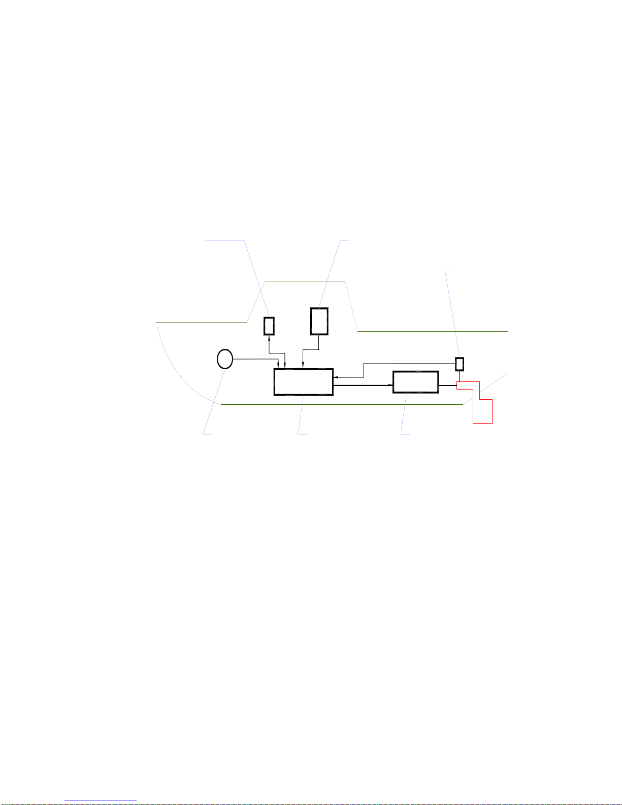
Figure 1 is a block diagram of the major components of an autopilot system.
CONTROL HEAD
DISPLAYS STATU S AND HEADING
INFORMATION FRO M TH E SPU , AND
ALLOWS THE OPERATOR TO INPUT
STEERING COMMANDS & OPER ATING
PARAMETERS
COMPASS
READS THE VESSEL'S
ACTUAL HEADING AND
SENDS IT TO THE SPU
Figure 1 – Basic Autopilot System
NAVIGATION DEVICES
[OPT ION AL ]
SUPPLY NAVIGATION
INFOMRATIO N TO THE SPU
IN NME A 0 1 8 3 F ORM AT
PROCESSOR (SPU)
CALCULATES THE RUDDER
POSITION N EEDED TO STEER
THE VESSEL ON THE DESIRED
HEADING, AND CONTROLS THE
STEERING SYSTEM
ACCORDINGLY
RUDDER FOLLOWER UNIT (RFU)
[MECHANICALLY CONNECTED TO RUDDER]
MEASURES RUDDER POSITION AND SENDS
IT T O T HE S PU
STEERING SYSTEM (ACTUATOR)
[HYD RA UL IC RA M OR EL E C TR IC MOT O R
WHICH IS MECHANICALLY CONNECTED
TO THE RUDDER]
MOVES THE RUDDER IN RESPONSE TO
CONTROL SIGNALS FROM THE SPU
The Compass indicates the direction in which the boat is pointed – often referred to as the
Actual Heading. Depending on the type of boat & installed equipment, the Compass may be
a magnetic compass, an electronic fluxgate compass, a gyroscopic compass, or a GPS
Compass. A reliable compass is absolutely vital to the autopilot – because, without a
compass, the autopilot has no way of knowing which way the boat is headed.
The actual heading is fed electronically from the Compass to the Processor (SPU) , which is
the heart of the autopilot. The SPU contains the microprocessor(s) & other electronic
hardware, and the sophisticated control software necessary to steer the boat on any Desired
Heading.
Document PN 29010074 V3.1 - 19 -
Page 20

ComNav Commander P2 Installation & Operation How Autopilots Work
The Control Head, normally located in the wheelhouse, is the interface between the user
(that’s you …) and the autopilot. The Control Head displays information about what the
autopilot is doing. It has various controls (buttons &/or knobs) that allow the user to give
commands to the Autopilot.
The final part of the picture is the Steering System. In order for the autopilot to steer the
boat, there must be some a steering system (i.e., actuator) capable of moving the rudder
independently of the ship’s wheel. This might be a hydraulic ram that is connected to the
rudder post or tiller quadrant, or an electric motor connected to the steering cables.
Electronic signals from the SPU signal the steering system to move the rudder. Your
autopilot also will have a Rudder Follower Unit (RFU), a device that tells the SPU what
position the rudder is in at any given time.
Autopilot Operation: Maintaining a Heading
Say, for example, the autopilot was steering your boat Southwest, and you wished to change
direction to Southeast.
That’s easy – if you are using your ComNav Autopilot in AUTO mode.
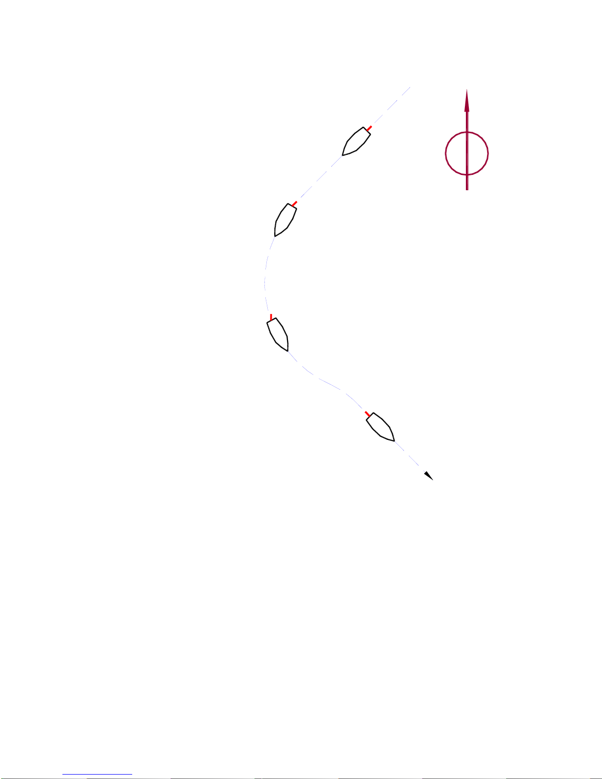
To initiate the turn, you would turn the knob on the Control Head to set the Desired Heading
(as shown on the Control Head’s display screen) to 135° – i.e., Southeast.
The SPU then would compare this to the boat’s current Actual Heading of 225° (Southwest),
as indicated by the Compass, and determine that the Desired Heading is 90° to Port of the
Actual Heading. This in turn would cause the SPU to send a signal to the steering system to
move the Rudder to Port – so that the boat turns to Port. The SPU verifies that the Rudder
has moved by reading its position from the Rudder Follower Unit.
As the boat turns, the difference between the Desired Heading and the Actual Heading gets
smaller, and as it does, the SPU then starts to ‘back off” the rudder – i.e., move it back to
centre – so that the boat does not overshoot the Desired Heading.
Eventually, the Actual Heading will match the Desired Heading. The SPU will keep steering
the boat on a heading of 135°, until new instructions are received from the Control Head.
Figure 2 shows a vessel making that Southwest-to-Southeast turn in AUTO mode.
ComNav Autopilots provide an important safety feature in AUTO mode: when you first select
the mode, the autopilot will use the current Actual Heading as the Desired Heading. This
feature prevents the autopilot from executing an unexpected turn when you first select AUTO
mode.
Document PN 29010074 V3.1 - 20 -
Page 21
ComNav Commander P2 Installation & Operation How Autopilots Work
N
Autopilot is steering vessel
on a heading of 225° (SW)
Operator selects new
desired heading of 135° (SE)
Autopilot responds to the
change in desired heading
by moving the rudder to
Port -- vessel begins to turn
As the actual heading
approaches the new desired
heading, the Autopilot starts
to move the rudder back
towards mid-ships position
Typical response is for the
Autopilot to "over-shoot"
the new heading slightly,
then straighten out
Figure 2 – Heading Change in AUTO Mode
Wind and Current Effects
If your boat encounters a crosswind, and/or a tidal current, at some angle to the Desired
Heading, it will be constantly pushed away from that heading, in the direction of the wind or
current. So the autopilot will constantly be making course corrections.
As that condition persists, the SPU will gradually begin to maintain the rudder a few degrees
to Port or Starboard of the centred position, to counter the effect of wind, and/or current. This
feature, known as trim, will keep your boat pointed in the right direction, despite the wind or
current.
However, one side-effect of trim is that your boat may not follow the Track you want – it will
maintain your Desired Heading, but the track will “slip” sideways in the direction of the
crosswind and/or current. This potential problem can be solved by using another mode that
ComNav Autopilots provide: NAV mode, described next.
Autopilot is now steering
the vessel on the new
heading of 135° (SE)
Document PN 29010074 V3.1 - 21 -
Page 22

ComNav Commander P2 Installation & Operation How Autopilots Work
Autopilot Operation: Following a Track – NAV Mode
So far, we have seen how an autopilot operates in AUTO mode: a new desired Heading must
be selected on the Control Head each time you wish to change direction. This is handy for
short trips or when you know the direct course to your objective.
But for longer trips, which might involve a number of legs at different headings, it would be
useful to be able to have your autopilot steer your boat along all the legs, in sequence.
ComNav autopilots allow you to do just that, with NAV mode.
Before using NAV mode:, the autopilot must be connected to an external source of navigation
information (commands & data) – such as a chart plotter, or a Navigation program running on
a PC. A source of position data is required, too; it may be built into the external Navigation
System, or it may be another device or system: a GPS receiver (such as a ComNav Vector
GPS Compass), a LORAN C receiver, etc.
ComNav Autopilots implement the industry-standard NMEA 0183 protocol for reception &
transmission of navigation information. Fortunately, almost all of today’s Navigation Systems
& Devices do comply with NMEA 0183, so interfacing those systems & devices to a ComNav
autopilot is relatively simple.
A long passage will consist of a series of waypoints, which are specific locations on the
Earth’s surface (hopefully on the water!) defined by their Latitude & Longitude. These
waypoints are entered into the external Navigation System by the user. That system
determines the current location of the boat (from the source of position data), and then
calculates the course that must be steered in order to reach the next waypoint.
1
When the Autopilot is switched into NAV mode, it begins to look for some specific navigation
information from the Navigation System: the course to steer to the next waypoint, and the
Cross-Track error (which is the distance from the boat to the desired Track from the last
waypoint to the next one). Using these two pieces of information, the autopilot steers the
boat on the shortest possible course to the next waypoint.
Crosswinds and/or currents are compensated for automatically each time the Navigation
System updates the cross-track error. This is why NAV mode is the answer to the “track slip”
problem that can occur in AUTO mode, when a crosswind/current exists.
When a waypoint is reached, the Navigation System sends the SPU the next set of
navigation information – for the next waypoint – and the SPU then turns the boat to head to
that next waypoint.
When the last waypoint is reached, the boat typically (depending on how the Navigation
System is set up) will orbit that waypoint, until the autopilot either is switched out of NAV
mode or is given new navigation information by the user, via the Navigation System.
Because the boat will turn automatically turn – without input from the user – at each waypoint,
when planning the trip it is crucial that the user verify that there will be sufficient room to
execute the turn at each waypoint.
The autopilot can be set to alert he user – by activating an alarm – as the boat nears a
waypoint.
1
… all such external devices are in general referred to in this manual with the generic term Navigation System.
Document PN 29010074 V3.1 - 22 -
Page 23

ComNav Commander P2 Installation & Operation How Autopilots Work
Autopilot Operation: Following a Track – AUTO/ALC Mode
Some ComNav autopilots provide another way to keep your boat on a specific Track:
Automatic Leeway Correction.
This feature – an element of ComNav’s unique Intelligent Steering Technology (also called
IST) – can be turned on in AUTO mode.
ALC is similar to NAV mode, in that it uses NMEA 0183 Latitude/Longitude data to sense if
the boat is following the desired Track.
Unlike NAV mode, however, a ComNav autopilot with the ALC feature only needs
Latitude/Longitude data in AUTO/ALC mode. It does not need Cross-Track error data from
the external Navigation System, nor that there be any waypoints set in the system. The IST
feature calculates the Cross-Track error on its own, using the desired heading active at the
point in time when AUTO/ALC mode is first engaged.
Power Steer
Most ComNav autopilots have a POWER STEER mode, which provides a way for the user to
directly control the rudder. Basically, the autopilot acts as a sort of “electronic steering
wheel”, allowing the operator to steer the vessel manually, in a similar way as when using a
standard manual steering wheel or tiller, but from the autopilot’s Control Head or any remote
controls it is equipped with.
Steering, when using the autopilot in this mode, is done with two buttons and/or a knob on
the Control Head. One button, and/or a clockwise turn of the knob, will move the rudder to
Starboard; the other button, and/or a counter-clockwise turn of the knob, will move the rudder
to Port.
Using the buttons/knob, the rudder can be placed in any desired position where it will remain.
This feature is useful when docking or manoeuvring, because the person steering the vessel
can take their hands off the controls between rudder movements.
Document PN 29010074 V3.1 - 23 -
Page 24

ComNav Commander P2 Installation & Operation
Document PN 29010074 V3.1 - 24 -
Page 25

ComNav Commander P2 Installation & Operation
System Overview
Document PN 29010074 V3.1 - 25 -
Page 26

ComNav Commander P2 Installation & Operation
Document PN 29010074 V3.1 - 26 -
Page 27
ComNav Commander P2 Installation & Operation System Overview
System Overview
This chapter gives a brief description of the major elements of the Commander P2 Advanced
Autopilot System, their functions, and their relationships to each other.
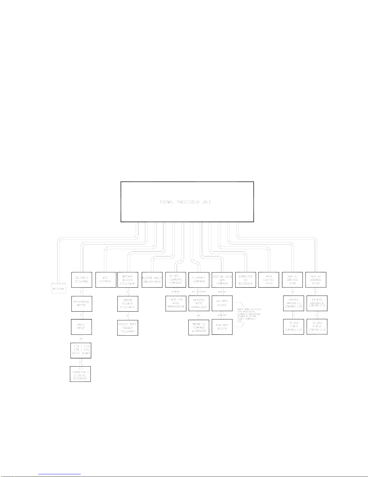
Below is a block diagram of a typical example of the Commander P2 system, showing the
interconnections between the elements of the system:
• The Signal Processor Unit (SPU)
• The Main Control Head
• A Compass or other Heading Sensor
• Solenoid(s), Reversing Motor, or Cable Drive, which move the Rudder
• The Rudder Feedback Unit
• Optional Auxiliary Control Head(s) & Remote Controls
• Various optional accessories & external equipment
• Other Navigation equipment
Figure 3 – Commander P2 System Block Diagram
Document PN 29010074 V3.1 - 27 -
Page 28
ComNav Commander P2 Installation & Operation System Overview
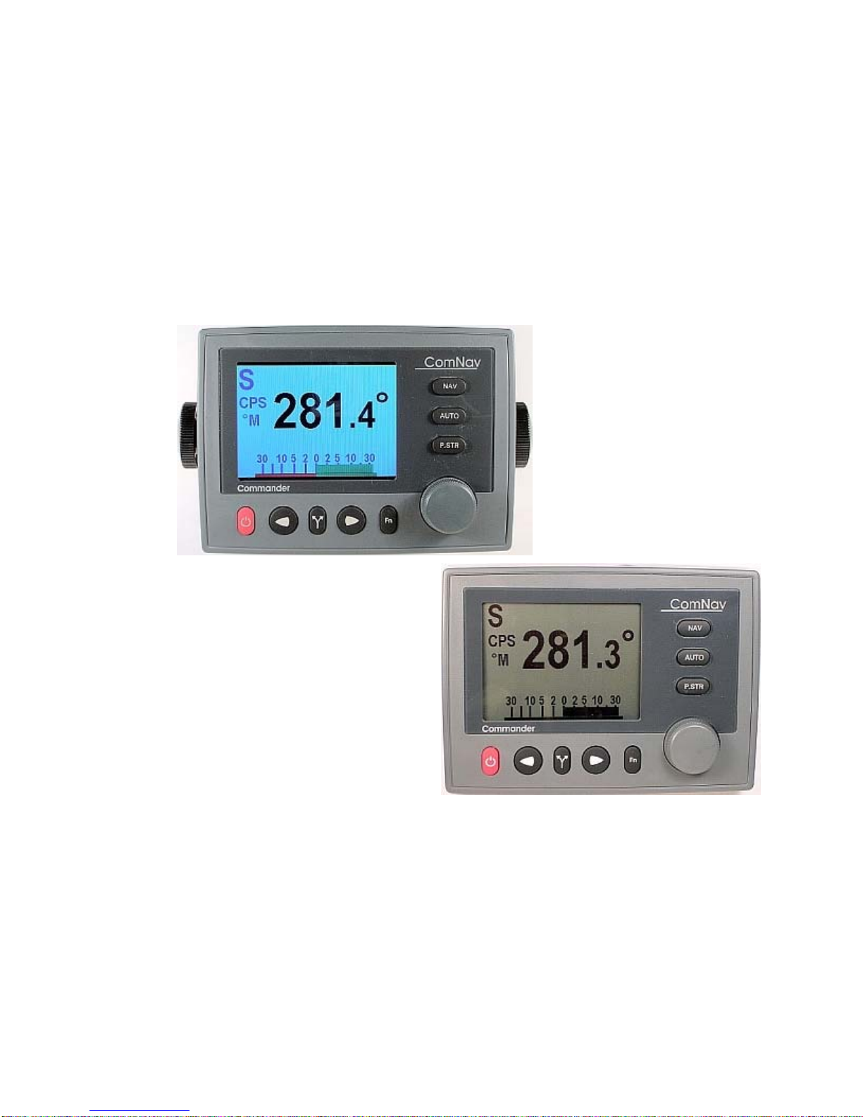
Control Head
PN 20110002 (monochrome)
PN 20110003 (colour)
The Commander P2 Control Head connects directly to the Signal Processor Unit (SPU), via a
nine-conductor cable that plugs into the rear of the Head. This cable wires onto a connector
supplied with the SPU; that connector in turn can quickly and easily be plugged into the
ONTROL HEAD receptacle on the SPU.
C
Two versions of the Commander P2 Control Head are available. Part Number 20110003
incorporates a state-of-the-art, sunlight-viewable, high resolution QVGA TFT colour LCD
display. PN 20110002 provides the exact same functionality, but has a silver-backed
monochrome LCD display.
Figure 4 – Control Head
The Control Head, when shipped as part of a complete Commander P2 system, is a “core”
module, with accessories for three mounting options: a snap-on sleeve for surface mounting,
a separate snap-on sleeve for flush mounting, and a two-piece bracket for bracket mounting.
All required hardware is included, except for two fasteners needed to fasten the bracket to a
mounting surface.
Document PN 29010074 V3.1 - 28 -
Page 29
ComNav Commander P2 Installation & Operation System Overview
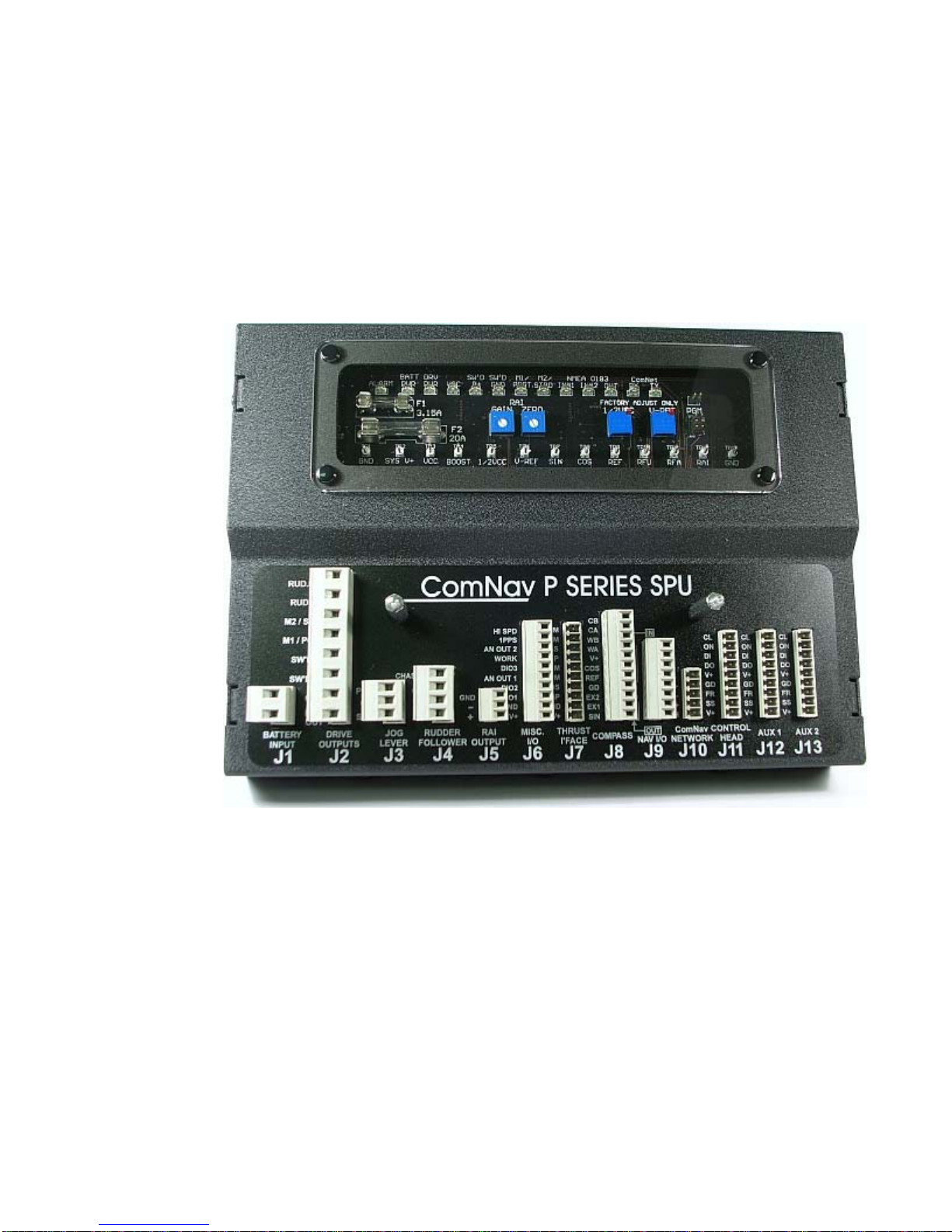
Signal Processor Unit
PN 20110006
The Signal Processor Unit (SPU), as its name suggests, accepts a number of signals from
the other components of the autopilot system, and processes them as necessary to control
the movement of the vessel’s rudder so as to maintain a given heading. As well as steering
the vessel, the sophisticated software within the SPU continually checks all aspects of the
autopilot’s performance, and will advise the user via the Control Head if any problems are
encountered.
Figure 5 – The Commander P2 SPU with Wiring & Diagnostic Covers Removed
Document PN 29010074 V3.1 - 29 -
Page 30
ComNav Commander P2 Installation & Operation System Overview
Compasses
The Compass is a critical component in the proper operation of the Commander P2 Autopilot
System. The autopilot system’s ability to steer the vessel to a given Heading desired by the
Operator can only be as accurate as the Compass.
The Commander P2 system is capable of using a variety of different compasses. These are
discussed below. Various combinations of these compasses, and related accessories, are
often required.
It is always a wise and safe choice to have at least two compasses,
and/or other Heading sensing devices, on board!
Vector G2 and G2B GPS Compasses
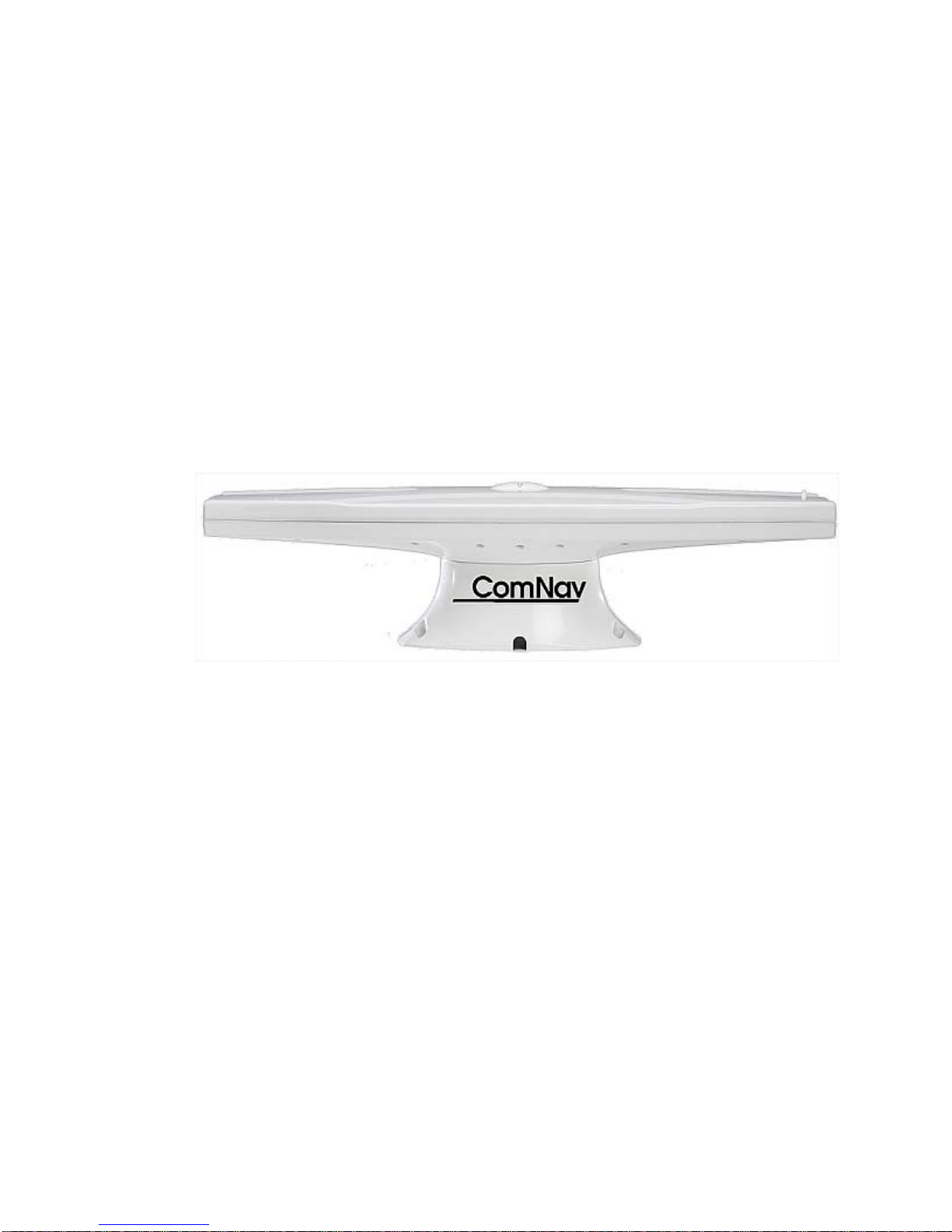
PN 11210001 (G2)
PN 11210004 (G2B)
The ComNav Vector GPS Compasses are state-of-the-art devices which provide accurate 2D
Heading & Position data to autopilots, sonar, chartplotters AIS transponders, and other
NMEA 0183 devices.
Figure 6 – Vector G2 GPS Compass
Built-in DGPS processing capability provides sub-meter Position accuracy. DGPS source
options in the G2 & G2B include standard SBAS systems (WAAS, EGNOS, MSAS, etc.), and
external RTCM SC-104; the G2B can also use terrestrial DGPS Radiobeacon signals
(IEC 61108-4), via an internal Beacon receiver module.
The Vectors feature fast start up times (< 1 minute), heading updates up to 20 times per
second, and continue to work correctly at sustained turn rates up to 90° per second.
The Vectors come with a choice of mounting styles: a flat-surface base, or a pole-mount
base. The entire unit is fully waterproof. The Vectors provide dual, independently
configurable, NMEA 0183 data outputs, each available at both NMEA 0183 standard output
voltages, and PC-friendly serial “COM port” voltages.
One feature of the Vectors is especially useful in marine applications: Heading is determined
by mathematical computation, directly from the RF signals from the GPS satellites, rather
than sensing the Earth’s magnetic field – and thus there are no local magnetic deviation
effects from metal objects, electrical devices & wiring, and so on.
The Vectors contain a solid-state Gyro sensor, which is used to provide Heading data in
situations where GPS signal reception is subject to transient interference. A Tilt sensor
measures the vessel’s Pitch (or Roll, depending on which way the unit is mounted), and the
data is used to remove any effects of Pitch/Roll on the Heading computation.
The Vector is connected to the Commander P2 at one of the SPU’s two NMEA Input ports.
The standard cable length is 15 metres (50’); 30 metres (100’) is also available.
Document PN 29010074 V3.1 - 30 -
Page 31
ComNav Commander P2 Installation & Operation System Overview
Fluxgate Compass
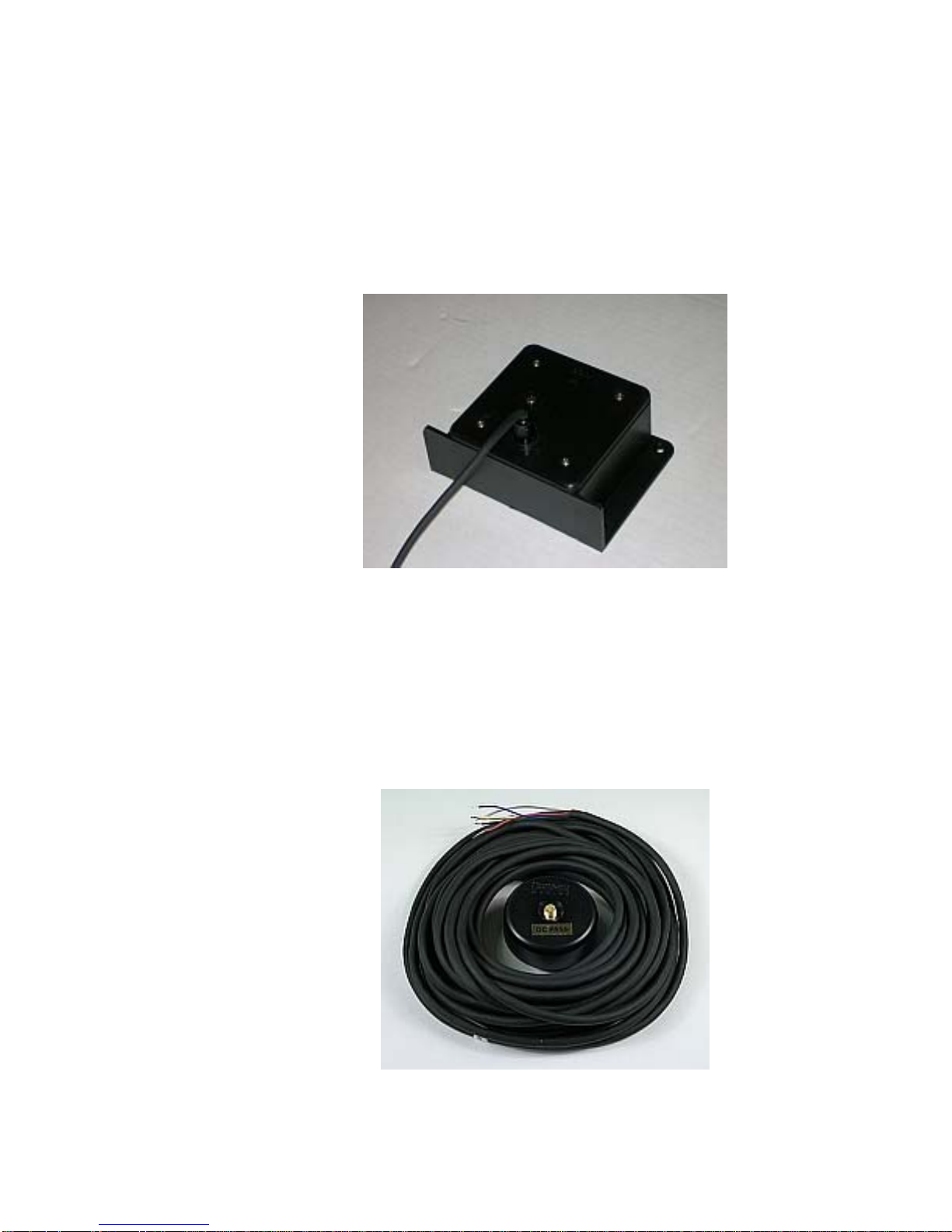
PN 20320004
Specifically designed for ComNav autopilots, the ComNav Fluxgate Compass directly senses
the Earth’s magnetic field. The unit incorporates a heeling coil for better performance when
the vessel is either rolling or heeled. The Fluxgate Compass is a sealed, waterproof unit
which may be mounted on a deck, shelf, or bulkhead. This compass outputs the traditional
analog compass signals – Sine & Cosine signals. It is supplied with a 12 metre (40’) cable;
an adapter cable (PN311100024) is required to wire it into the Commander P2’s SPU.
Figure 7 – Fluxgate Compass
Magnetic Compass Sensor
PN 20320002
The ComNav Magnetic Compass Sensor detects the position of the compass card of an
externally gimballed magnetic compass. The sealed unit can be attached to the bottom of
any of ComNav’s Magnetic Compasses, or the bottom or top of many other brands of
externally gimballed magnetic compasses. It is wired directly to the SPU, with the attached
25’ cable.
Figure 8 – Magnetic Compass Sensor
Document PN 29010074 V3.1 - 31 -
Page 32
ComNav Commander P2 Installation & Operation System Overview
Magnetic Compasses
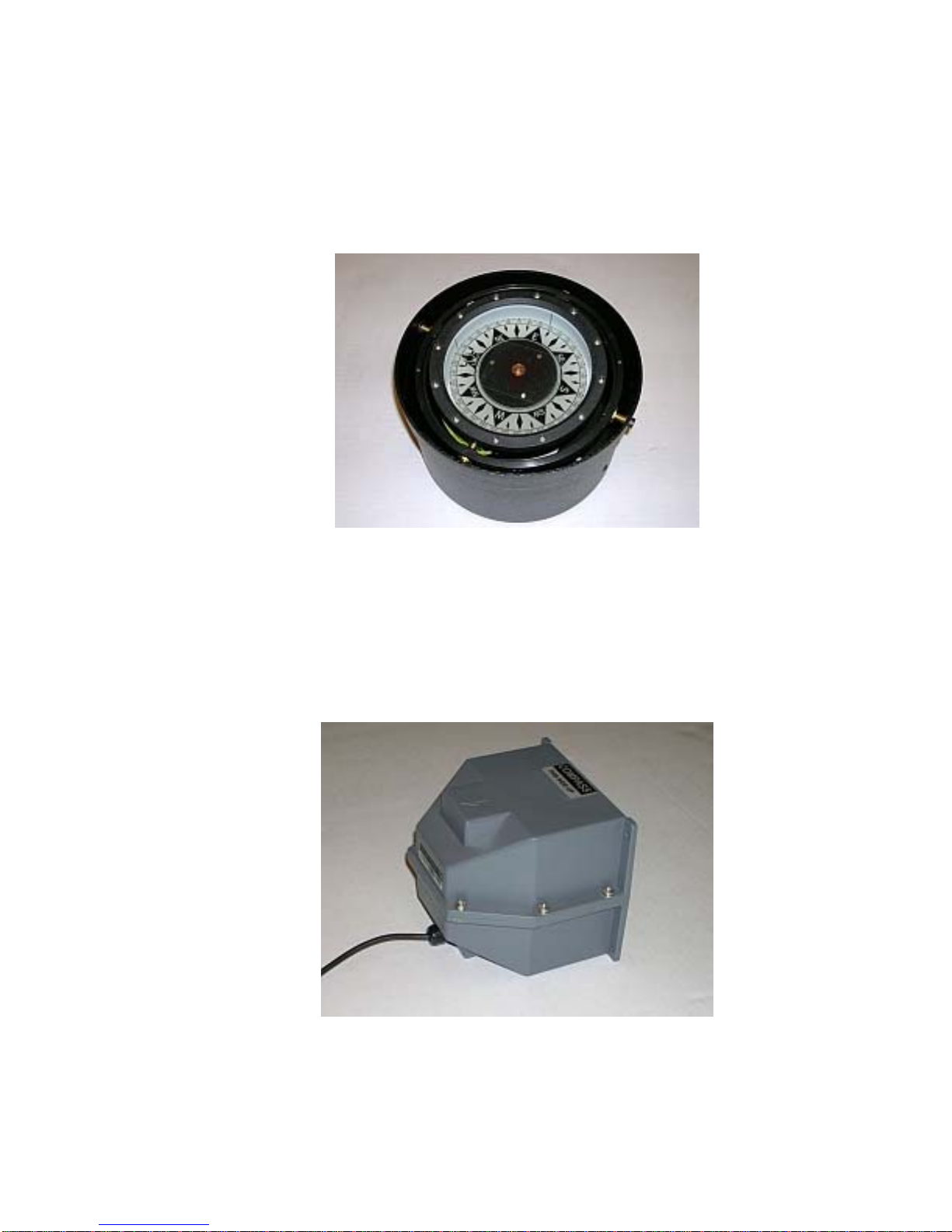
ComNav offers several high quality externally gimballed Magnetic Compasses, of either 5” or
6” diameter, which are directly compatible with the ComNav Magnetic Compass Sensor.
These compasses are available in either bracket mount or binnacle mount. Compensating
spheres and arms are also available. Consult your ComNav Dealer for part numbers.
Figure 9 – Externally Gimballed Magnetic Compass with Binnacle
45° Compass Transducer
PN 20640006
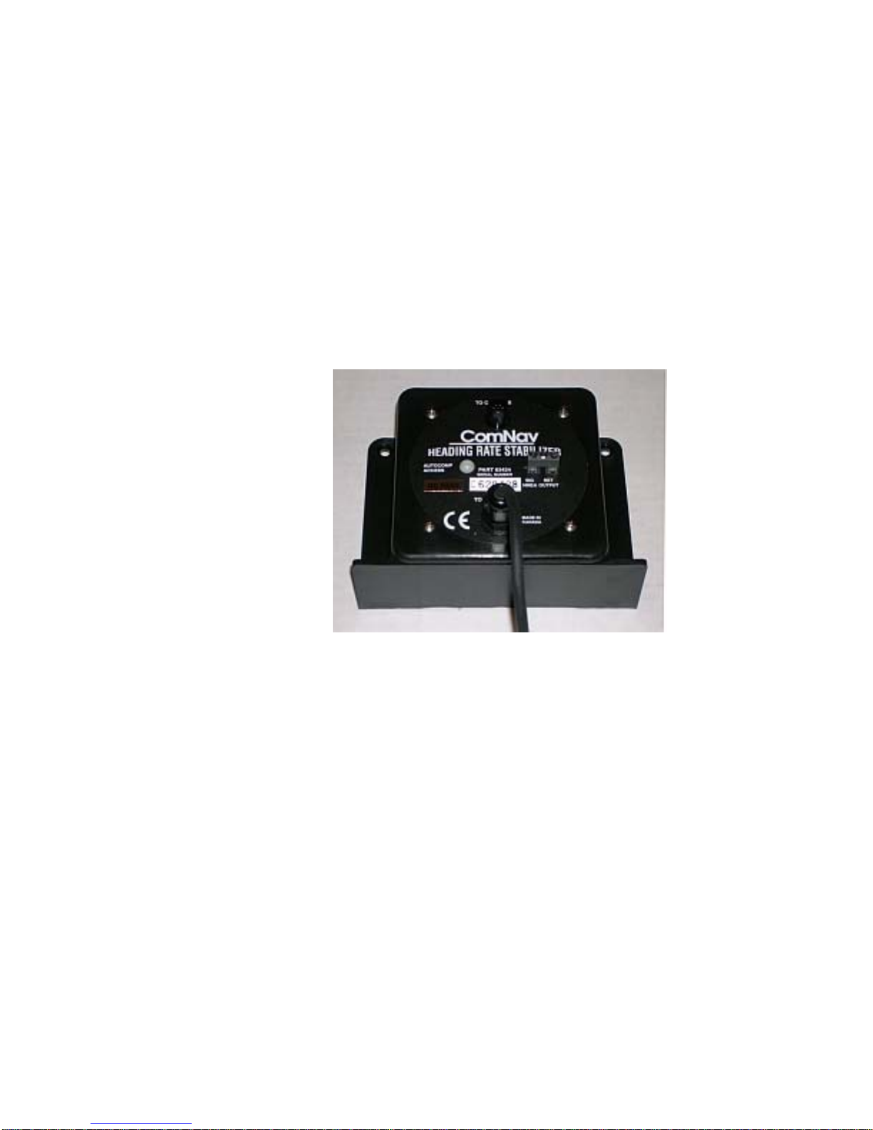
The ComNav 45° Compass Transducer contains a fluid-damped fluxgate sensor and works
at heeling angles up to 45°. This compass puts out a proprietary digital Sine/Cosine signal.
It is wired directly to the SPU.
Figure 10 – 45° Compass Transducer
Document PN 29010074 V3.1 - 32 -
Page 33
ComNav Commander P2 Installation & Operation System Overview
Heading Rate Stabilizer
PN 20320005
Perhaps the single greatest factor affecting Autopilot performance is the quality of the
compass heading information it receives. Compass error due to pitch and roll, high turn rates
and high-speed turns are common to both fluxgate and magnetic compasses.
Northerly turning error is another phenomenon that affects both types of compasses,
particularly at higher latitudes, due to an increase in the earth’s vertical magnetic field
component.
The sideways acceleration of a vessel in a high speed turn will also affect the accuracy of
compasses.
ComNav’s Heading Rate Stabilizer minimizes the effect of these factors.
Figure 11 – Heading Rate Stabilizer
The Heading Rate Stabilizer measures the horizontal component of the rate of change in the
vessel’s heading, and adjusts the compass reading to minimize the effects of pitch and roll,
fast turn rates and northerly turning error.
The heading output provided to the Autopilot is dramatically improved in terms of dynamic
responsiveness and stability, enabling the Autopilot to perform more accurately and
efficiently.
The ComNav Heading Rate Stabilizer is designed to work with ComNav’s Fluxgate Compass
(PN 20320004).
Other Compasses
ComNav recommends the use of ComNav’s own compasses for the best performance of the
Commander P2 Advanced Autopilot system – but you certainly may decide to use either a
fluxgate compass or a magnetic compass from another manufacturer. See your ComNav
Dealer or consult the factory for information on interfacing these compasses with the
Commander P2 system.
Document PN 29010074 V3.1 - 33 -
Page 34
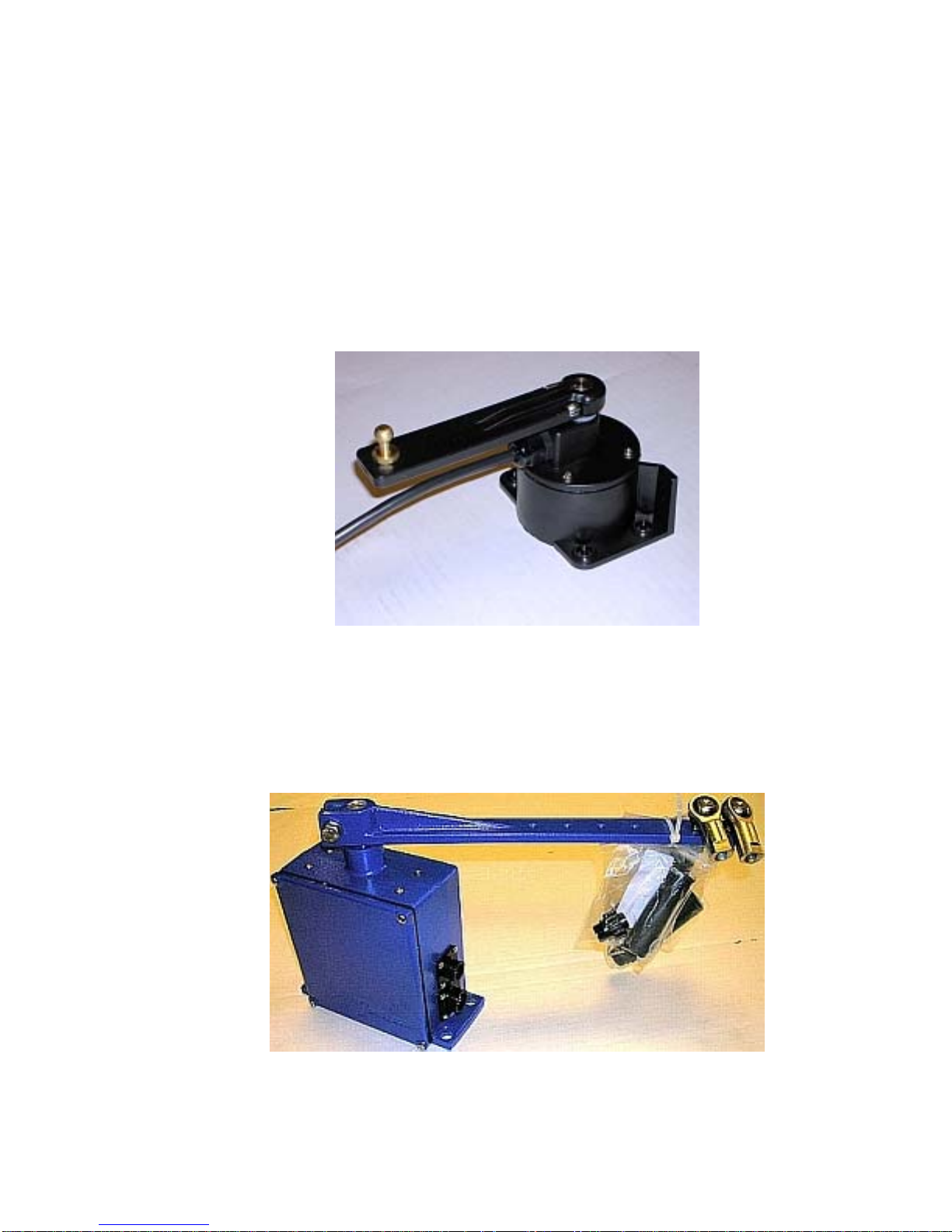
ComNav Commander P2 Installation & Operation System Overview
Rudder Followers
Standard Rotary Rudder Follower & Rudder Linkage
PN 20330008 & 20330007
The ComNav Commander P2 is normally supplied with a ComNav Medium Duty Rotary
Rudder Follower.
The Rudder Follower is used to transmit the position of the vessel’s rudder to the SPU. It
should be connected to whichever part of the steering system the autopilot controls.
Normally, this is the vessel’s rudder. However, if the vessel has two-stage steering, where
the autopilot drives a control or servo ram, the Rudder Follower should be mounted to the
servo ram rather than the rudder.
Figure 12 – Rotary Rudder Follower
Heavy Duty Rotary Rudder Follower
PN 20330012
A Heavy Duty Rotary Rudder Follower is available for special applications. Check with your
ComNav Dealer to determine whether this product is suitable for your vessel. Separate
installation instructions are provided with this Rudder Follower.
Figure 13 – Heavy Duty Rotary Rudder Follower
Document PN 29010074 V3.1 - 34 -
Page 35
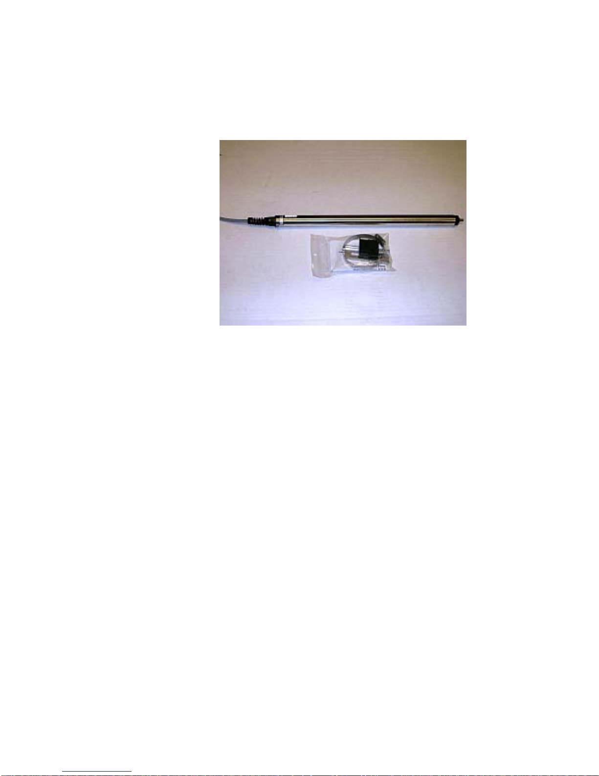
ComNav Commander P2 Installation & Operation System Overview
Linear Rudder Follower
PN 20330002
Installations on vessels with outboard motors may use a ComNav Linear Rudder Follower.
Figure 14 – Linear Rudder Follower
Document PN 29010074 V3.1 - 35 -
Page 36
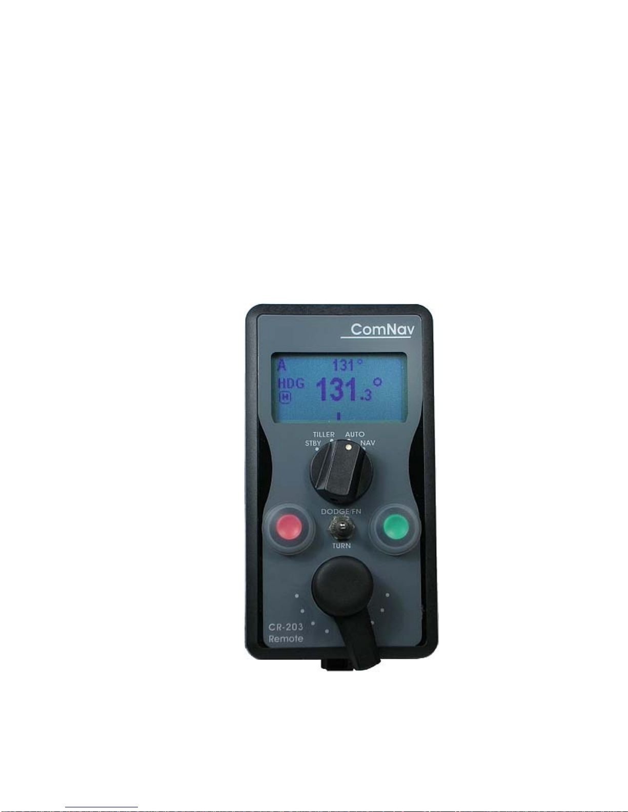
ComNav Commander P2 Installation & Operation System Overview
Auxiliary Controllers
Up to two Auxiliary Controllers may be added to the standard Commander P2 system. These
may be any combination of Commander Control Heads (colour and/or monochrome),
CR-203 Handheld Remotes, and TS-203 Fixed Remotes.
CR-203 Remote
PN 20310026 – 12m (40’) cable
PN 20310028 – 18m (60’) cable
The CR-203 Handheld Remote is specifically designed to operate with the Commander P2
Advanced Autopilot System. The CR-203 Remote provides selection of STANDBY, TILLER,
AUTO, and NAV mode. In TILLER mode, the vessel’s rudder position is tied to the position
of the CR-203’s Tiller knob. In STANDBY, AUTO & NAV modes, the CR-203 operates
identically to the Commander P2’s Control Head. The CR-203 Remote supports WORK
mode (Refer to WORK Mode in the Advanced Operations chapter for an explanation of that
mode).
Document PN 29010074 V3.1 - 36 -
Figure 15 – CR-203 Handheld Remote
Page 37
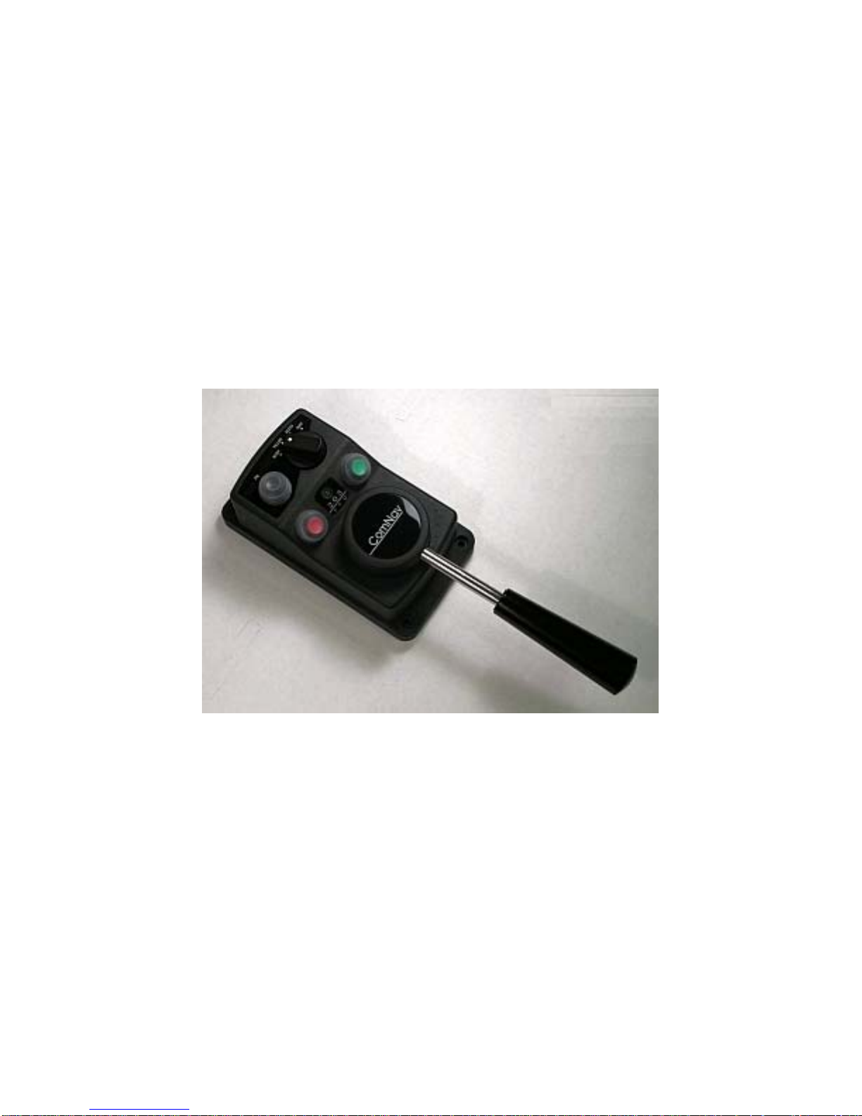
ComNav Commander P2 Installation & Operation System Overview
TS-203 Remote
PN 20310025 – 12m (40’) cable
PN 20310030 – 18m (60’) cable
PM 30310011 – Ball Knob Kit
The TS-203 Fixed Remote is a heavy duty Full-Follow-Up (FFU) Lever control which allows
the operator to control the tiller steering and autopilot functions from any work station, flying
bridge or remote location on the vessel.
The optional Ball Knob Kit is a replacement for the TS-203’s standard tapered-handle Tiller
lever. It is intended to be used where a “ball handle” is preferable, or in installations where
there is limited space in which to mount the TS-203. The kit’s ball & shaft are the same as
used on ComNav Jog Levers. The total ball-shaft length is 12 cm (5”), as compared to the
TS-203’s standard handle-shaft length of 18 cm (7”).
Figure 16 – TS-203 Fixed Remote
Document PN 29010074 V3.1 - 37 -
Page 38
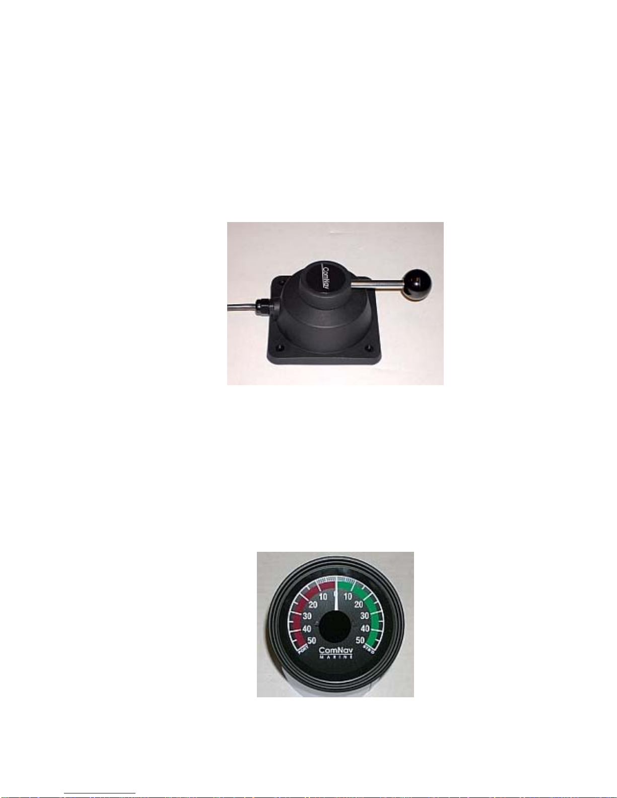
ComNav Commander P2 Installation & Operation System Overview
Other Controls, Indicators & Sensors
Jog Levers
PN 20310002 (1 set of switches)
PN 20310003 (2 sets of switches)
ComNav’s NFU (Non-Follow-Up) Jog Lever is a permanently mounted, watertight, electrical
switch specifically designed for marine use. The spring-centered lever is moved port or
starboard as desired to provide non-follow-up (time dependent) electrical control of the
vessel’s steering system.
Figure 17 – Jog Lever
Rudder Angle Indicator (RAI) – 3”
PN 20360014
The ComNav RAI is a backlit 3” (76 mm) diameter gauge that displays the actual position of
the vessel’s rudder. The RAI is flush mounted, encased in high impact resistant
polycarbonate plastic with a water resistant front face, and requires a lighting voltage supply
of 12, 24 or 32 VDC.
An optional Bezel Kit (Part # 30360004), Wheelhouse Case (PN 20360017) and Watertight
Case (PN 20360016) are available.
Figure 18 – External Rudder Angle Indicator - 3" Model
Document PN 29010074 V3.1 - 38 -
Page 39
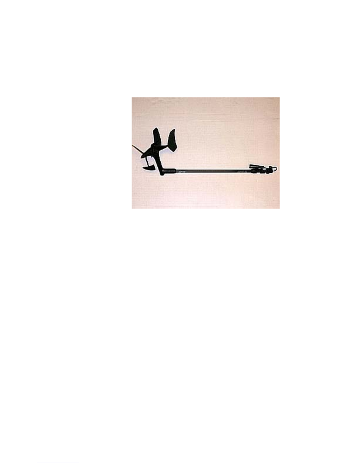
ComNav Commander P2 Installation & Operation System Overview
Twin-Fin Wind Transducer
PN 20640020
For use with sailboats, ComNav’s Twin-Fin Wind Transducer provides accurate wind speed
and wind angle data to the Commander P2 SPU. This allows the vessel to steer to a specific
angle relative to the wind. An easy, snap-in attachment for mast mounting is included.
Figure 19 – Twin-Fin Wind Transducer
The Twin-Fin Transducer can be “shared”: a Commander P2 and a ComNav NX2 Wind Data
Instrument (PN 20620050), or a full NX2 Network System (various PNs), can be wired at the
same time to the transducer (see page 63 for details).
Document PN 29010074 V3.1 - 39 -
Page 40
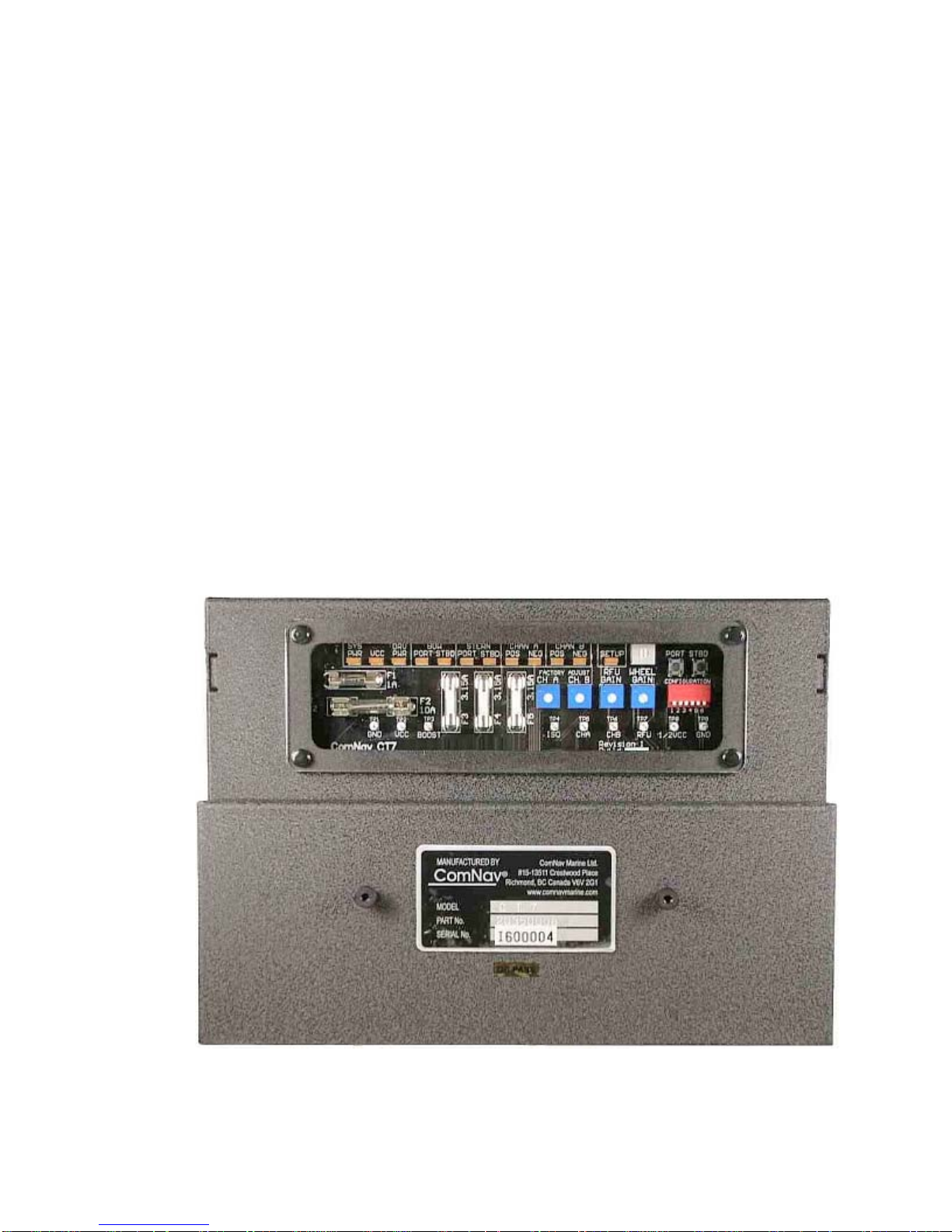
ComNav Commander P2 Installation & Operation System Overview
Rudder Drives and Interfaces
CT7 Thruster Interface
PN 20350008
The optional CT7 Interface is highly recommended when the Commander P2 Autopilot
System is being used on a vessel equipped with Bow and/or Stern Thrusters, or when the
vessel is equipped with Azimuth Drives (as known as Z-Drives) of various types.
The CT7 is specifically designed to be directly compatible with, and complementary to, the
Commander P2 system, in features, operation, and appearance. It connects directly to the
Commander P2’s SPU with a dedicated cable that carries power and all control/data signals.
The CT7 can operate a number of different solenoid valves, including on/off and proportional
types.
It has standard voltage outputs, current loop outputs and optically-isolated analog outputs.
The CT7 also contains circuitry for interfacing an Electric Wheel to the Commander P2
system, and a Rudder Simulator which is used when the CT7 is interfaced to Azimuth Drives.
The Commander P2’s SPU has built-in setup & operational firmware support for the CT7; the
firmware activates automatically when a CT7 is plugged into the SPU at the J7 - T
INTERFACE connector.
HRUSTER
See the CT7 Installation & Operation Manual for full details, and setup & operating
instructions.
Figure 20 – CT7 Interface
Document PN 29010074 V3.1 - 40 -
Page 41
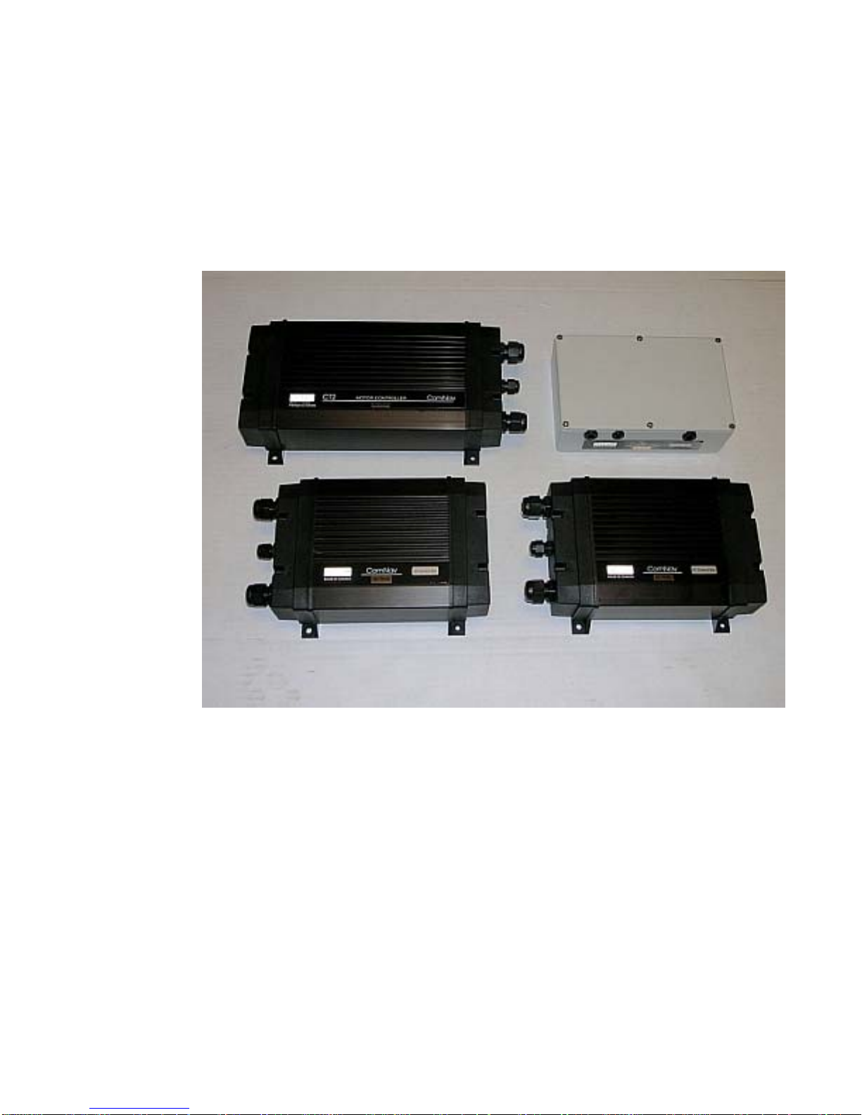
ComNav Commander P2 Installation & Operation System Overview
Other Drive Boxes
The Commander P2 system is capable of directly operating steering systems utilizing
reversing DC motors or single speed solenoids.
ComNav also manufactures a complete line of Drive Boxes that will interface the steering
outputs from the Commander P2 system to almost any type of steering system.
Contact your ComNav Dealer for information and specific part numbers.
Figure 21 – Drive Boxes to meet all needs
Document PN 29010074 V3.1 - 41 -
Page 42
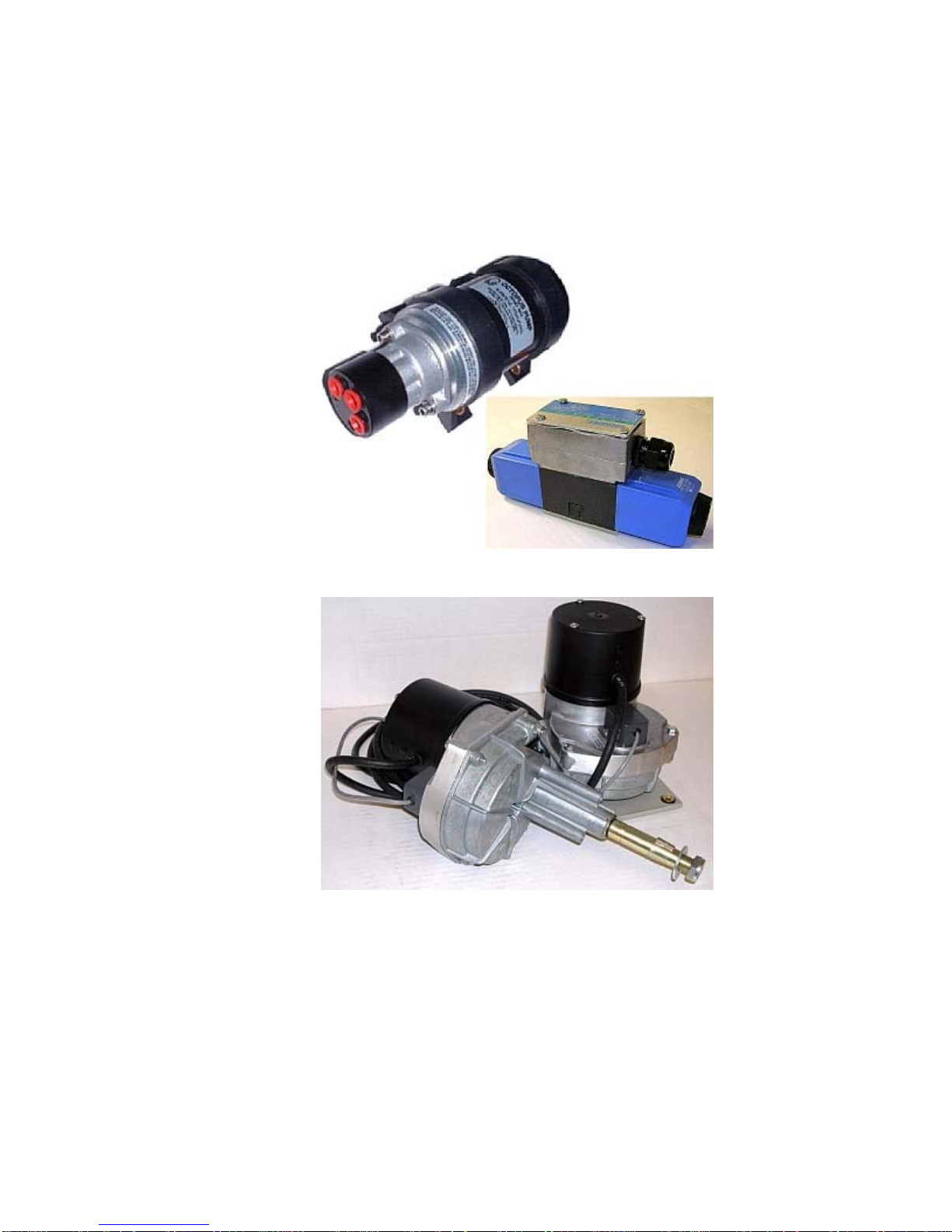
ComNav Commander P2 Installation & Operation System Overview
Pumps & Drives
ComNav offers several types of electric-motor Hydraulic Pumps, matching Solenoid Values &
related equipment, as well as a number of high-quality Cable Drives and accessories.
Each drive comes with its own Installation Manual.
Please contact your ComNav Dealer for information and details.
Figure 22 – Hydraulic Pump & Solenoid Value
Figure 23 – Cable Drives
Other Equipment
Besides the optional equipment described above, there is a wide choice of other equipment
available for use with the Commander P2 Advanced Autopilot system.
Contact your ComNav Dealer for information and details.
Document PN 29010074 V3.1 - 42 -
Page 43

ComNav Commander P2 Installation & Operation
Installation
Document PN 29010074 V3.1 - 43 -
Page 44

ComNav Commander P2 Installation & Operation
Document PN 29010074 V3.1 - 44 -
Page 45

ComNav Commander P2 Installation & Operation Installation
Installation
This chapter describes all the steps you must follow while doing the physical installation of
the Commander P2 Advanced Autopilot System on your vessel.
Each of the standard components of a P2 system is described – both physical mounting &
electrical wiring – and then some final checks are given. Commonly-used accessories are
also described. Many components come with their own specific instructions, and you should
pay attention to those, as well.
Technical Requirements
Please refer to the Warranty Information document that accompanies
this manual before proceeding with installation.
Hazard warning!
CAUTION!
Extreme caution is advised when using tools powered by alternating
current (AC) from main AC supply circuits, regardless of whether the
supply circuits are “indoor”, “outdoor”, “marine” or “industrial” rated.
Water, especially sea water, is an
and can complete a path to AC Ground through a person’s body,
causing injury or death, if a tool malfunctions or short-circuits.
EXCELLENT conductor of electricity,
⇒ Battery powered tools are STRONGLY recommended ⇐
If AC tools are used, they MUST be plugged into a circuit that is
adequately protected against Ground Faults and other safety hazards,
in accordance with local electrical codes.
Steering System
To obtain the best performance from your Autopilot, your vessel’s steering system must be in
good working order. The hydraulic system should be bled, and should be operating with
minimal play.
When installing a Reversing Motor Pump, a Constant Running Pump, or an Engine Driven
Pump, it is recommended that you install shutoff valves on all hydraulic lines between the
Pump and the steering system.
Power Supply
For reliable operation of your Autopilot, your vessel’s power supply system must have an
adequately-breakered, or fused, DC (direct current) power supply at a nominal voltage of
either 12 or 24 volts. If the circuits are fused, a switch should also be provided. Ensure that
adequate wire sizes are used to handle the expected maximum currents.
Special Tools
A slot screwdriver with a tip size of ~2.5 mm (0.1”) is required, for tightening the small screws
of the wire clamps in the plugs which mate with the SPU’s pin-receptacle connectors.
Other general-purpose tools such as a portable drill, pliers, wire cutters, screwdrivers, wire,
mounting bolts and wrenches will also be required.
Document PN 29010074 V3.1 - 45 -
Page 46

ComNav Commander P2 Installation & Operation Installation
Control Head
The Control Head is normally mounted in the vessel’s wheelhouse. It can also be mounted in
more exposed locations, such as on a flying bridge, since it is fully waterproof. Note that,
although it is waterproof, it is not submersible, nor should it be exposed to prolonged direct
sunlight. The Control Head comes with a 7.65 metre (25’) cable. The cable has a 9-pin
circular connector on one end and flying leads on the other. These leads are wired into a
push-on connector that mates with the SPU. The cable and Head-end connector are fully
waterproof.
Mounting
Each Control Head is supplied (when ordered as part of Commander P2 system kits) with
three mounting kits -- one for bracket mounting (PN 30110006), one for surface mounting
(PN 30110004), and one for flush-mounting (PN 30110003). Each one is packaged in a
separate bag.
Complete instructions, including drilling/cutting templates for each type of mounting are
contained within the bag for each kit.
In addition, there is a fourth bag containing a number of screws, washers, and nuts
(PN 30110005). The fasteners in this bag are to be used with either the surface mount kit or
the flush-mount kit. They are not used for bracket-mount installations.
Electrical Connection
Route the Control Head Cable from the Control head to the location where the SPU will be
located. Avoid running the cable parallel to antenna cables, AC power, or DC wires/cables
carrying heavy current.
Excess Control head Cable can be coiled up, or the cable can be trimmed to a more
appropriate length.
See Control Head on page 60 for details on connecting the cable to the SPU.
Document PN 29010074 V3.1 - 46 -
Page 47

ComNav Commander P2 Installation & Operation Installation
Compasses
The ComNav Commander P2 is usually supplied with either a ComNav’s Fluxgate Compass
(optionally with a Heading Rate Stabilizer), a 45° Compass Transducer, or a Magnetic
Compass Sensor (for use with an externally-gimballed traditional magnetic compass).
System packages with the ComNav Vector G2 (or G2B) GPS Compass are also available.
The choice of compass depends on the type and intended use of the vessel. Refer to the
appropriate section below for installation instructions for your magnetic compass.
• If you have a Vector G2 or G2B Compass (or other NMEA Compass), please refer to the
Installation & Operation Manual that came with it.
When first installed, most magnetic compasses will have Deviation. Deviation is the error
between the compass reading and the vessel’s actual Magnetic heading. Deviation is a
result of magnetic fields induced in the vessel’s hull (on steel vessels), and fields from objects
such as engines, davits, galley equipment, etc., and electrical/electronic systems & wiring.
If you have a ComNav Fluxgate Compass (with or without HRS) or a 45° Compass
Transducer, the Commander P2 can electronically compensate for the Deviation. The
compensation procedure is done during the Sea Trials. If you have a magnetic compass, it
will have to be manually compensated. A professional compass adjuster often does this job.
If you intend to use a fluxgate compass other than a ComNav Fluxgate Compass, or if you
are using a magnetic compass not supplied by ComNav, you should contact the dealer you
purchased it from, or the manufacturer, for instructions on how to install and set up your
compass.
Note: Do not permanently install any compasses until sea trials are
complete. Depending on the outcome of the sea trials, it may be
necessary to relocate the compass(es).
ComNav Fluxgate Compass
Mounting
Choose a location for the Fluxgate Compass. For best performance, the Fluxgate Compass
must be mounted as close as possible to the vessel’s center of pitch and roll. This is typically
low in the vessel, at or about the waterline, and slightly aft of the center of the vessel.
You must keep the compass as far away as possible – at least 2 metres (about 6’) – from
engines, electric motors, and other magnetic objects.
Holes are provided to attach the Fluxgate Compass to either a bulkhead or to a horizontal
shelf or deck. The compass must be mounted parallel to, and as close as possible to the
centerline. The compass must be mounted with the correct side up (that is, with the cable
coming out of the top of the unit). The arrow labelled “BOW” should point forward.
Electrical Connection
Route the Fluxgate Compass cable from the Fluxgate Compass to the location where the
SPU will be. Avoid running the cable parallel to antenna cables, AC power, or DC
wires/cables carrying heavy current.
Excess cable should be coiled up; ComNav recommends that the cable NOT be shortened.
If the cable is too short, plug-in Compass Extension Cables are available in various lengths
from your ComNav Dealer. Cutting and splicing the Fluxgate Compass cable is NOT
recommended.
See Compasses on page 62 for further details on connecting the cable to the SPU.
Document PN 29010074 V3.1 - 47 -
Page 48

ComNav Commander P2 Installation & Operation Installation
Heading Rate Stabilizer
The HRS is an optional accessory for the ComNav Fluxgate Compass.
Please refer to the All Models information in the Installation Instructions that come with the
HRS, for mounting & electrical wiring information.
See Compasses on page 62 for further details on connecting the HRS cable to the SPU.
45° Compass Transducer
Mounting
Choose a location for the Compass Transducer. For best performance, it should be mounted
as close as possible to the vessel’s center of pitch and roll. This is typically low in the vessel,
at or about the waterline, and slightly aft of the center of the vessel.
You must keep the compass as far away as possible, at least 2m (about 6’) away from
engines, electric motors, and other magnetic objects.
Holes are provided to attach the Compass Transducer to a bulkhead. The compass must be
mounted parallel to the centerline. The compass must be mounted with the correct side up
(the label that says “Compass” must be on top), and the arrow should point forward.
Electrical Connection
Route the Compass Transducer cable from the compass to the location where the SPU will
be. Avoid running the cable parallel to antenna cables, AC power, or DC wires/cables
carrying heavy current.
Excess cable should be coiled up. The cable may be shortened if desired to avoid excess
coils. If the cable is too short, additional cable may be ordered from your ComNav Dealer.
See Compasses on page 62 for further details on connecting the cable to the SPU.
Magnetic Compass and Sensor
The ComNav Magnetic Sensor can be mounted to ComNav’s standard Magnetic
Compasses, and also to a wide variety of other brands of externally gimballed compasses.
The advantage of using a Magnetic Compass with a Magnetic Compass Sensor attached to it
is that the Autopilot is sensing the position of the magnets on the compass card rather than
sensing the earth’s magnetic field directly.
Since the card of the compass has physical inertia, it does not react immediately to the
changes in the magnetic field it is immersed in, but only to those changes which persist long
enough to overcome the resistance of the compass card to movement. This means that the
compass is a more stable heading reference than a Fluxgate Compass. The Magnetic
Compass will largely ignore changes in the magnetic field in the plane of the compass card
caused by vessel motion to which the Fluxgate Compass may react.
This is particularly important in high latitudes, (such as Alaska, Labrador or the North Sea),
where the horizontal component of the earth’s magnetic field (which is the portion that the
compass is trying to detect) is very small relative to the magnetic field of the vessel.
The disadvantage of the Magnetic Compass is that in very rough weather with the vessel
going to windward, it is possible for the vessel motion to upset or “tumble” the compass card,
disabling the Autopilot.
Because of the relative insensitivity of the Magnetic Compass to both the earth’s and the
vessel’s vertical magnetic fields (due to its inertia), it is recommended for use at latitudes
higher than 50° (North or South), and for use on steel vessels when optional quadrantal
spheres are included.
Document PN 29010074 V3.1 - 48 -
Page 49

ComNav Commander P2 Installation & Operation Installation
Locate and mount the compass in a position that minimizes magnetic interference. The
compass should be at least 1 metre [about 3’] away from such equipment as radios, radars,
depth sounders, and engine instruments.
To reduce the possibility of the card ‘tumbling’ in rough weather, mount the compass as close
as practical to the center of pitch and roll. Mounting the compass far forward under a bunk or
similar location is a poor choice for rough weather performance.
Important! It is important to remember that the compass is a vital part of
the autopilot system. Locating it properly, particularly on steel-hulled
vessels, is essential to ensure proper operation of the autopilot. ComNav
strongly recommends that the services of a qualified compass adjuster be
used to select the best installation location, and to compensate the compass
properly for deviation, including that caused by heeling error.
Care must be taken not to place compensating magnets too close to the compass, as this will
cause the Compass Sensor, mounted underneath the compass, to read incorrectly. To
correct compass deviation on steel vessels, or on other vessels with magnetic compensating
problems due to interference from adjacent ferrous masses such as an engine block or
winches, the use of a pair of compensating quadrantal spheres is recommended.
Note: the ComNav Magnetic Sensor SHOULD NOT be attached to an internally gimballed
compass (that is, where the compass card is gimballed and the bowl of the compass is not),
as this will result in large errors between the compass and the autopilot. This is because the
compass card does not remain parallel to the sensor when the vessel rolls or pitches.
Mounting
The Sensor can be mounted to the bottom of the compass using the brass screw supplied, or
it may be bonded directly to the compass bowl using a suitable adhesive. The Nylon Washer
should be placed between the Compass Sensor and the bottom of the compass bowl.
When the Sensor mounts to the bottom of the bowl, the magnetic compass may be used as a
steering compass, if desired.
It is also possible to mount the Sensor above the compass. This reduces the possibility of
interference from the compensating magnets, but also reduces the visibility of the compass.
Optimum positioning of the sensor can only be accomplished once the Autopilot system has
been installed and powered up. See the Getting Started chapter of the manual to perform
this procedure.
Electrical Connection
Route the Magnetic Compass Sensor cable from the Compass to the location where the SPU
will be. Avoid running the cable parallel to antenna cables, AC power, or DC wires/cables
carrying heavy current.
Ensure that there is sufficient slack in the cable to allow the compass bowl to tilt and rotate
freely in all directions.
Excess cable should be coiled up; ComNav recommends that the cable NOT be shortened.
If the cable is too short, plug-in Compass Extension Cables are available in various lengths
from your ComNav Dealer. Cutting and splicing the Magnetic Sensor cable is NOT
recommended.
See Compasses on page 62 for further details on connecting the cable to the SPU.
Document PN 29010074 V3.1 - 49 -
Page 50

ComNav Commander P2 Installation & Operation Installation
Rudder Follower
The Rudder Follower is used to transmit the position of the rudder back to the Autopilot. It
should be connected to whatever parts of the steering system the Autopilot controls.
Normally, this will be the vessel’s rudder. However, if the vessel has a two-stage steering
system where the Autopilot drives a control or servo ram, the Rudder Follower should be
mounted to the servo ram rather than to the rudder.
Normally the Rudder Follower is mounted in the stern of the vessel, close to the rudder post.
A mounting base may have to be fabricated to position the Rudder Follower properly. Mount
the Rudder Follower in a location where the possibility of damage from any equipment
stowed in the area is minimized.
Note: If you are connecting the Commander P2 to a mechanical Cable
Drive (for vessels that use cable steering instead of hydraulic steering),
the rudder follower is built into the Cable Drive. See the Cable Drive
Installation Manual for details.
Rotary Rudder Follower
Mounting
Mount the Rudder Post Arm on the rudder post using a stainless steel band clamp (not
supplied). Bolt the ball joint to the hole in the Rudder Post Arm corresponding to the
diameter of the Rudder Post in inches, making sure the ball is facing upwards.
Mount the Rudder Follower so that the Rudder Follower Arm is the same height as the
Rudder Post Arm. The Rudder Follower is centered when the arm is directly above the cable
gland (see Figure 24).
The distance between the centerline of the Rudder Post and the Rudder Follower must not
exceed 24 inches. Make sure that the ball joints on the Rudder Arm and Rudder Follower
arm are facing upwards as shown in Figure 3.
Snap the rod assembly onto the ball joints. Be sure to close the release clamps on each
socket. Refer to Figure 24, and adjust the length of the rod to get the correct geometry with
the rudder dead-ahead.
If the locking screw in the Rudder Follower arm has been loosened, or the arm removed from
the Rudder Follower, re-attach the arm and check the potentiometer center position.
When the rudder is dead-ahead, the electrical resistance between the wires of the black &
green wire pair, and the wires of the white & green wire pair, should be equal (approx. 600
ohms each).
Be careful to check the installation for any mechanical obstructions or binding of the linkage,
and correct it now, before it becomes a problem.
Document PN 29010074 V3.1 - 50 -
Page 51
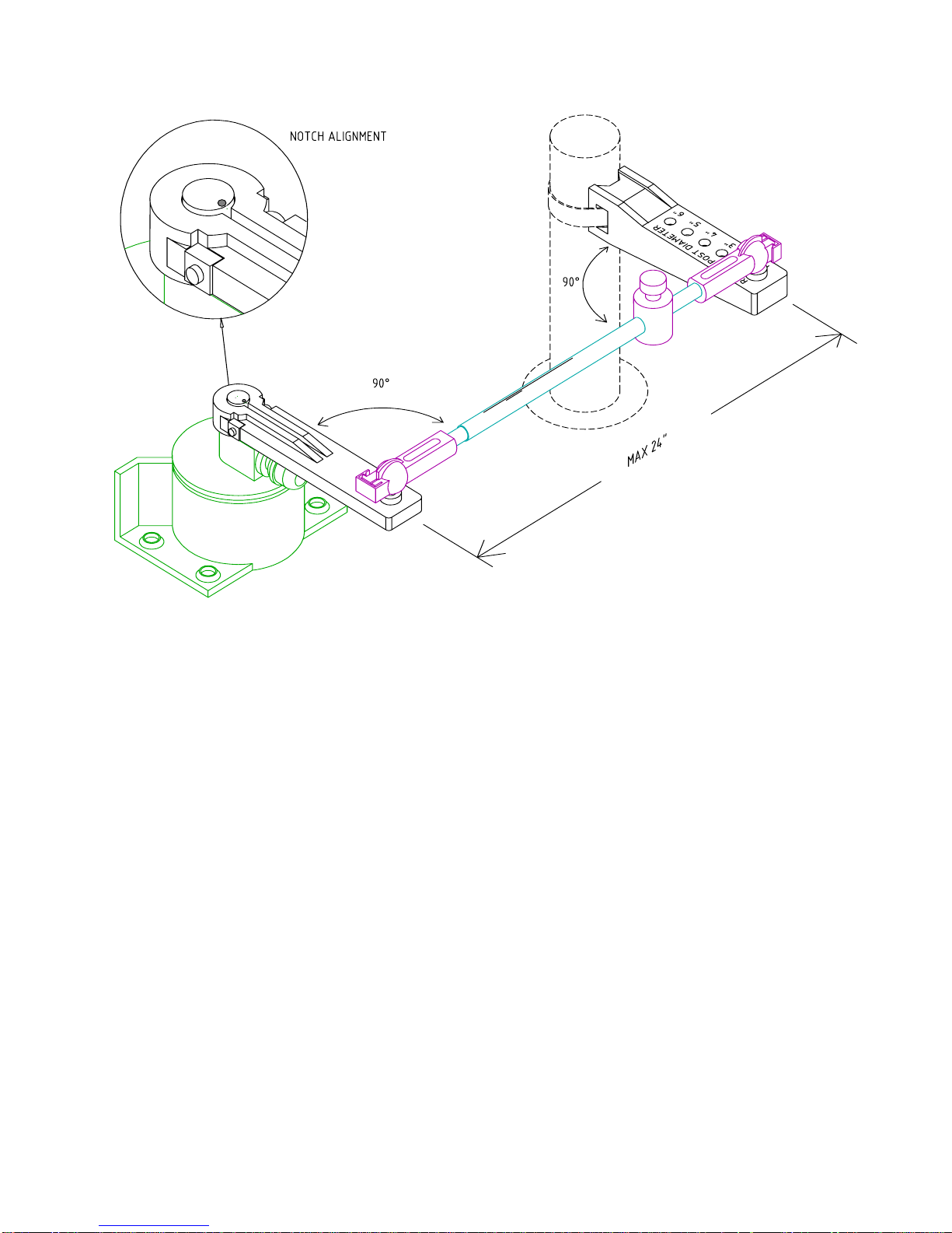
ComNav Commander P2 Installation & Operation Installation
Figure 24 – Rudder Follower Linkage Geometry
Electrical Connection
The Rudder Follower is normally supplied with approximately 15.5 metres (50’) of cable. Run
the cable from the Rudder Follower towards the SPU, ensuring that a hose or conduit
protects it wherever it passes through bulkheads, holds, or any other area where it could be
damaged.
If the length of cable supplied is too short to reach all the way to the SPU, obtain a terminal
strip and sufficient additional cable from your ComNav Dealer. Mount the terminal strip in a
convenient DRY location where it will not be subjected to moisture of any kind.
See Rudder Follower on page 63 for further details on connecting the cable to the SPU.
Heavy Duty Rotary Rudder Follower
The ComNav Heavy Duty Rotary Rudder Follower is also compatible with the Commander
P2 Advanced Autopilot System. If you have purchased one of these devices, follow the
installation instructions supplied with the unit.
See Rudder Follower on page 63 for further details on connecting the cable to the SPU.
Document PN 29010074 V3.1 - 51 -
Page 52
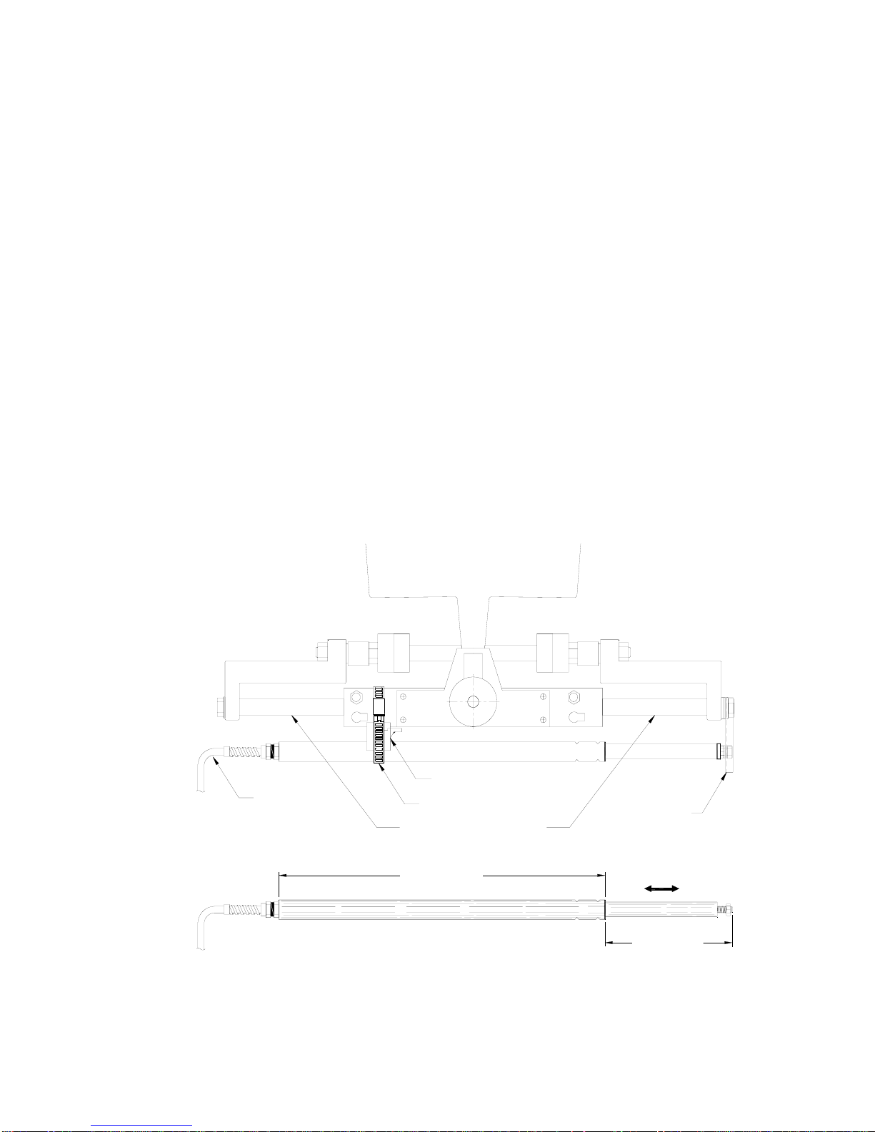
ComNav Commander P2 Installation & Operation Installation
Linear Rudder Follower
Mounting
Step 1:
If the Linear Rudder Follower is to be mounted with the sliding rod facing towards the port
side of the vessel, turn the steering wheel so the motor is hard over to starboard.
If the Linear Rudder Follower is to be mounted with the sliding rod facing towards the
starboard side of the vessel, turn the steering wheel so the motor is hard over to port.
Step 2:
Carefully measure the travel of the outboard motor’s steering cylinder. It must not exceed
25.4 cm (10”). If it is more than that, corrosion resistant spacers will need to be fabricated to
go over the rod of the hydraulic cylinder to limit its travel (see Figure 25).
Caution! If the travel of the steering cylinder is more than 25.4 cm
(10”), the Linear Rudder Follower will be over-extended, causing it to be
damaged or destroyed.
There is no warranty on the Linear Rudder Follower
STEERING CYLINDER
30 FOOT (9.1 METER)
CABLE TO AUTOPILOT
for damage due to over-extension.
OUTBOARD
MOTOR
TWO PIECE
CLAMP
STAINLESS STEEL
BAND CLAMP
ADD SPACERS IF NECESSARY TO LIMIT
TRAVEL TO 10 INCHES / 254 MM (MAX.)
15.2 INCHES / 386 MM
OUTBOARD FEEDBACK
(SEE DIMENSIONS BELOW)
STAINLESS STEEL
BRACKET
SLIDING RO D
Figure 25 – Typical Arrangement of Linear Rudder Follower on an Outboard’s Steering Cylinder
Document PN 29010074 V3.1 - 52 -
OUTBOARD FEEDBACK
MATERIAL - STAINLESS STEEL & PLASTIC
5 INCHES / 127MM
(0 - 10.5 INCHES / 0 - 267 MM)
Page 53
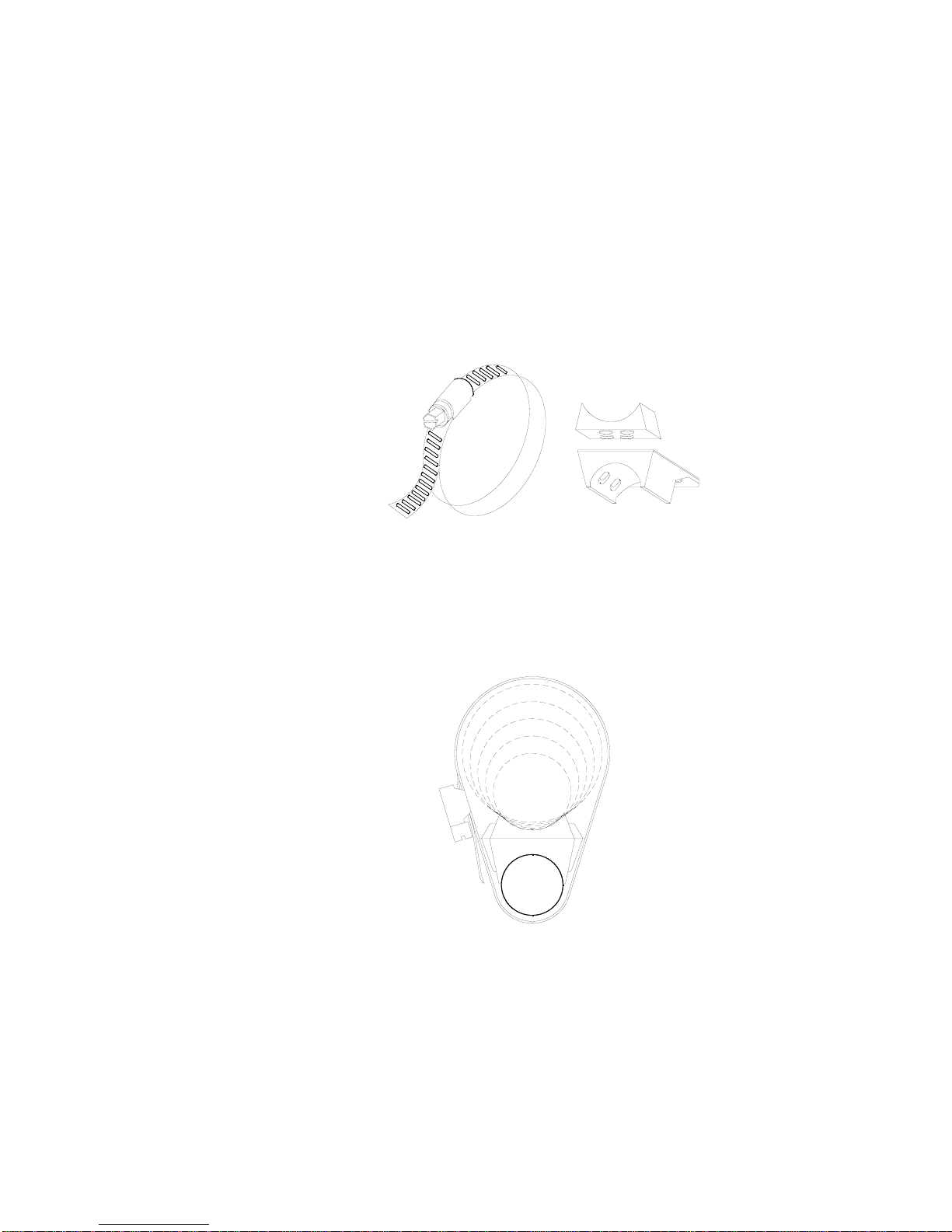
ComNav Commander P2 Installation & Operation Installation
Step 3:
The clamps and band should be positioned as far as possible towards the end of the Linear
Rudder Follower which has the cable that goes to the autopilot (see Figure 25). Loosely
place the stainless steel band clamp around the Linear Rudder Follower and the outboard’s
steering cylinder.
Place the larger plastic mount bracket on the Rudder Follower, curved face on the Follower.
Place the smaller plastic mount bracket on the steering cylinder, curved face on the cylinder
body. Loosely tighten the band clamp around the Rudder Follower, the cylinder and the
brackets (see Figure 26 and Figure 27).
STAINLESS STEEL
BAND CLAMP
TWO PIECE PLASTIC
MOUNT BRACKETS
Figure 26 – Band Clamp and Plastic Brackets
2.25
2.00
STAINLESS STEEL
BAND CLAMP
1.75
1.50
1.25
STEERING CYLINDER
TWO PIECE
BRACKETS
OUTBOARD
FEEDBACK
1.25 - 2.25 INCH. DIA.
Figure 27 – Installed Arrangement of Brackets
Document PN 29010074 V3.1 - 53 -
Page 54
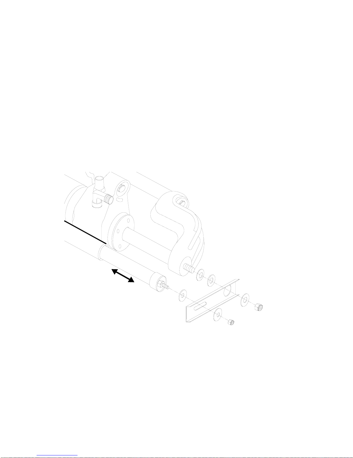
ComNav Commander P2 Installation & Operation Installation
Step 4:
Remove the nut from the steering cylinder rod’s end (see Figure 28). Place the thick nylon
flat washer (1.57 mm / 0.062” thick), then the thinner nylon flat washer (0.81 mm / 0.032”
thick) and lastly the stainless steel bracket, over the threaded end of the rod. Place the
stainless steel flat washer on the other side of bracket, and then replace the cylinder rod’s
nut. Do not tighten it yet – just thread it part-way, far enough to stay on.
Step 5:
Extend the sliding rod completely out of the Linear Rudder Follower. Push it back in slightly
(about 3mm / 1/8”). Adjust the position of the Follower so that the end of the sliding rod is
flush with the stainless bracket. Place the nylon washer between the nut and the stainless
steel bracket. Place the stainless steel washer on the other side of bracket, and screw the
Nylock nut part-way onto the threaded rod at the end of the Linear Rudder Follower.
Carefully adjust the position of the Linear Rudder Follower so that it is parallel with the
hydraulic cylinder, in both horizontal and vertical planes.
Finally, tighten both nuts and the stainless steel band clamp securely.
NYLON FLATWASHER
7/16" x 3/4" x 0.062"
SLIDING ROD
NYLON FLATWASHER
1/4" x 5/8"
STAINLESS STEEL
BRACKET
SS FLATWASHER
Figure 28 – Fasteners, Stainless Bracket Arrangement
Caution! To avoid the possibility of contaminants entering the Linear
Rudder Follower, it is advisable to occasionally wipe the sliding rod,
while it is fully extended, with a clean rag.
If you trailer your vessel, it is especially important to do this on a regular
basis. A good time to clean the rod is during the on-shore preparation
for every launch – since that will take care of any “road grime” picked up
during the trip to the launching ramp.
NYLON FLATWASHER
7/16" x 3/4" x 0.032"
SS NYLOCK
1/4"
NUT 1/4-20
SS FLATWASHER
1/2" x 7/8" x 0.032"
REMOVED NUT
SUPPLIED WITH
CYLINDER
Document PN 29010074 V3.1 - 54 -
Page 55

ComNav Commander P2 Installation & Operation Installation
Electrical Connection
The Linear Rudder Follower is normally supplied with approximately 9.5 metres (30’) of cable.
Run the cable from the Linear Rudder Follower towards the SPU, ensuring that a hose or
conduit protects it wherever it passes through bulkheads, holds, or any other area where it
could be damaged.
If the length of cable supplied is too short to reach all the way to the SPU, obtain a terminal
strip and sufficient additional cable from your ComNav Dealer. Mount the terminal strip in a
convenient DRY location where it will not be subjected to moisture of any kind.
See Rudder Follower on page 63 for further details on connecting the cable to the SPU.
Other Equipment
You should install the remaining components of your Commander P2 system according to the
installation instructions that come with that equipment:
• Auxiliary Controllers
• Jog Levers
• Rudder Angle Indicators
• Wind Transducers
• a CT7 Thruster Interface or a Drive Box
• Pumps & Drives
• etc.
Electrical wiring instructions for all these are a combination of the information in the individual
equipment’s manual, and specific information for the Commander P2 which is given in the
following sections of this chapter.
Document PN 29010074 V3.1 - 55 -
Page 56

ComNav Commander P2 Installation & Operation Installation
Signal Processor Unit
Mounting
The SPU should be mounted in a clean and DRY area, away from heat, moisture, and water
of any kind. The SPU should be centrally located, and mounted far enough away from your
vessel’s compasses so as to minimize any possible electrical interference; a good
rule-of-thumb is at least 1 metre (3’) – but see Compass Safe Distances on page 180 for
specific values, if you do not have that much space.
The SPU can be mounted vertically on a bulkhead or horizontally on a deck or shelf.
• If mounted vertically, it should be positioned so that all wires and cables will exit from
the bottom of the SPU (after running sideways, left &/or right as appropriate, from the
SPU connectors under the SPU’s wiring cover).
• If mounted horizontally, all wires and cables should have a drip-loop formed in them.
Each SPU is shipped from the factory with a package of four mounting feet and a separate
instruction sheet that includes dimensions for drilling holes to fasten the feet to the vessel.
Wiring the SPU - General
Due to the relatively high current requirements of an autopilot compared to many other types
of electronic equipment, the size of wire used to connect the various components is very
important. Undersized wiring will result in power losses which can affect overall efficiency
and performance. Refer to the table below If in doubt, contact your ComNav Dealer for help.
Function / Use Type / Gauge
SPU Power Supply 2 X 12 AWG
Steering Drive: 12/24/32 VDC Solenoid Valve 3 X 18 AWG
2 X 14 AWG
Steering Drive: Reversing Motor
(refer to the instructions supplied
with the Drive Motor)
Rudder Follower 3 X 18 AWG Shielded cable
GPS, Chartplotter, Navigation Computer 2 X 24 AWG Shielded cable
Rudder Angle Indicator 2 X 24 AWG
Table 1 – Minimum Recommended Wire Gauges
Once the SPU is securely mounted, you can begin wiring the various components of the
system, one at a time.
Start by removing the Wiring Cover from the SPU. It is held in place by two knurled plastic
nuts (see Figure 29).
Set the covers & nuts aside – they will be re-installed once all the wiring of the SPU is
complete.
Document PN 29010074 V3.1 - 56 -
Page 57
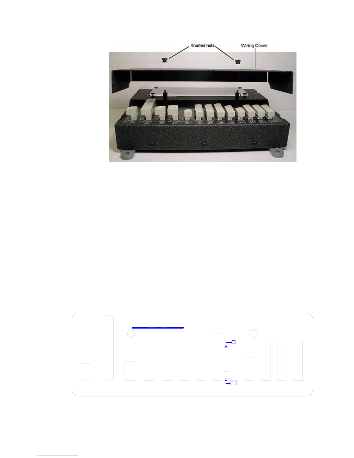
ComNav Commander P2 Installation & Operation Installation
Figure 29 – Removal of SPU Wiring Cover
Connectors on the SPU
With the wiring cover off, all the SPU’s connectors are visible (see Figure 5 & Figure 30).
Each connector is a pin receptacle, with the pins sized according to how much current will be
carried (bigger pins for higher current). Each pin has a signal name, rather than a number, to
make it easier to match wires with pins (see connector label, below).
Each pin receptacle mates with a matching plug, which in turn has screw-clamp terminals,
into which the wires from the external equipment & devices (battery, drive system,
compasses, etc.) are inserted. The plugs allow quick installation & removal of system wiring,
yet are fully secure, once the various cables are strain-relieved and the wiring cover is
re-installed.
The SPU is shipped with all the plugs required, pre-installed on the matching receptacles.
Note that the plug screws must be turned counter-clockwise several turns (using the small
slotted screwdriver mentioned on page 45 – Special Tools) , to open up the plug’s wire
clamp, before a wire is inserted into that clamp; the screw must then be turned clockwise until
the wire is tightly held in the clamp.
All connectors and pins are labelled, as shown in the figure below.
+
B
-
B
BATTERY
INPUT
RUD.RET
RUD.SIG
M2 / STBD
M1 / PORT
SW'D B-
SW'D B+
J1
GND
PWR
OUT
DRIVE
OUTPUTS
J2
PORT
GND
STBD
ComNav
CHASSIS
GND
SIG
+5V
RUDDER
JOG
FOLLOWER
LEVER
J3
J4
GND
-
+
AN OUT 2
AN OUT 1
RAI
OUTPUT
J5
HI SPD
1 PPS
WORK
P SERIES SPU
SS
SP
BS
BP
V+
THRUST
I'FACE
CB
CA
WB
WA
V+
COS
REF
GD
EX2
EX1
SIN
COMPASS
DIO3
DIO2
DIO1
GND
V+
MISC.
I/O
J6
SSM
SPM
BSM
BPM
GND
IN
2B
2A
1B
1A
CH
GD
B
A
OUT
NAV I/O
J9J7 J8 J10
C-
C+
PSPS+
SH
ComNav
NETWORK
CL
ON
DI
DO
V+
GD
FR
SS
V+
CONTROL
HEAD
J11
CL CL
ONON
DI DI
DODO
V+
V+
GD GD
FRFR
SS SS
V+
V+
AUX 1 AUX 2
J12 J13
Figure 30 – SPU Connector Wiring Label
Document PN 29010074 V3.1 - 57 -
Page 58
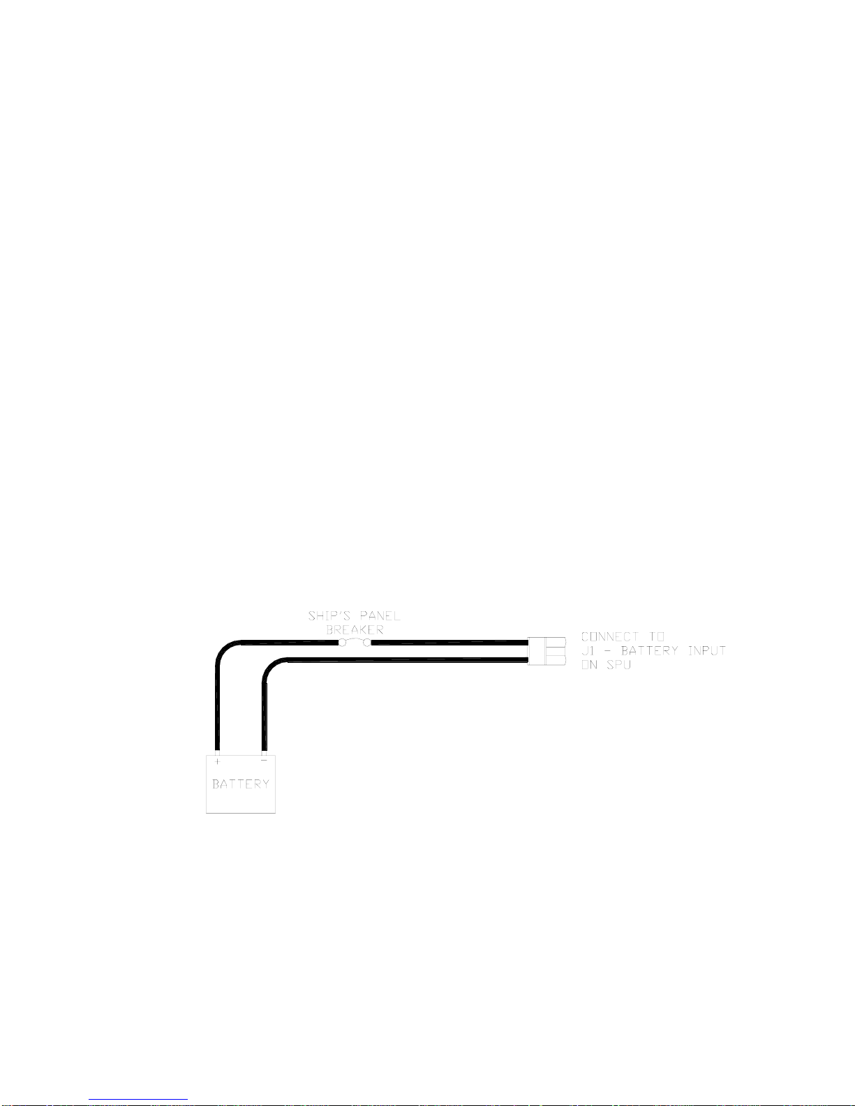
ComNav Commander P2 Installation & Operation Installation
Wiring the System
Power Supply
The ComNav Commander P2 will operate on any voltage between about 11 VDC and
30 VDC. This allows operation with vessel battery systems of nominal voltages from 12 to 24
VDC.
Caution! Do not power up the SPU until you have completed the installation,
and performed the steps outlined in “Post-Installation Checks”.
Generally, wiring for the positive leg of a DC system will be red or white, while wiring for the
negative leg (usually referred to as Ground) will be black.
Power to supply the autopilot should be taken directly from a breaker or distribution panel.
The autopilot should be wired into its own individual breaker or fuse. Using appropriately
sized wire or cable (see Table 1 – Minimum Recommended Wire Gauges on page 56), wire
the battery connections to the connector plug and receptacle labelled J1 - B
Double-check the wiring polarity before inserting the plug into the receptacle.
Caution! The Commander P2 SPU is NOT reverse-polarity protected.
ATTERY INPUT.
⇒
If you wire the wrong voltage polarity at J1, you WILL damage the SPU and Head! ⇐
⇒
This will also void the Warranty. ⇐
Refer to the following diagram of a typical power supply circuit:
Figure 31 – Typical Battery Connection to SPU
Document PN 29010074 V3.1 - 58 -
Page 59
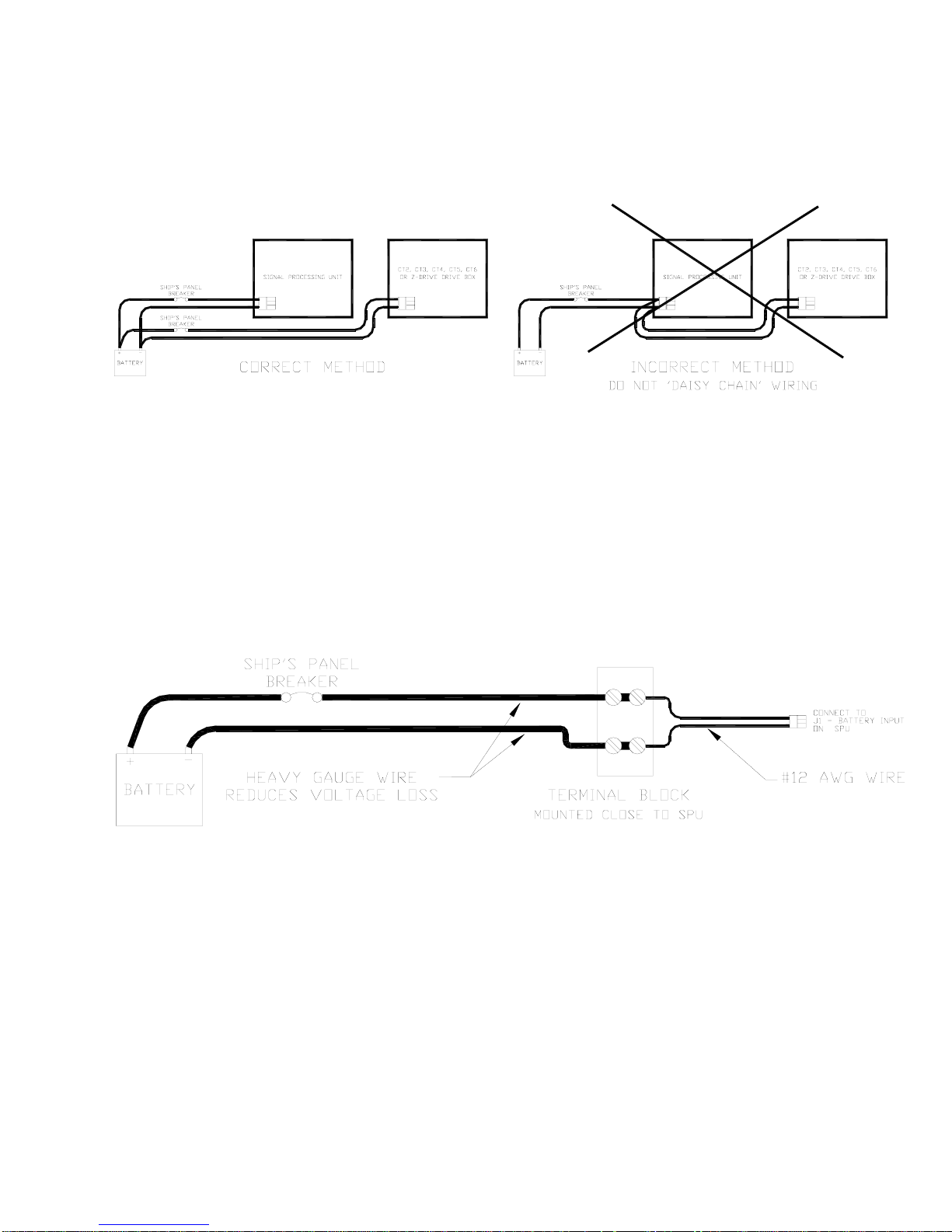
ComNav Commander P2 Installation & Operation Installation
Note: If your autopilot system utilizes one of ComNav’s CT Drive Boxes, it should be wired
back to the breaker or fuse separately from the rest of the autopilot system. Do not “daisychain” the power wires.
Figure 32 – Typical Battery Connection to Drive Boxes
If the SPU is mounted a long distance from the ship’s breaker panel, it is recommended that
heavy gauge wire be routed between the breaker panel and a terminal block mounted in
close proximity to the SPU. #12 AWG wire can then be used between the terminal block and
the SPU. This minimizes any voltage drop between the breaker panel and the SPU.
Figure 33 – Reducing Supply Voltage Losses
Document PN 29010074 V3.1 - 59 -
Page 60
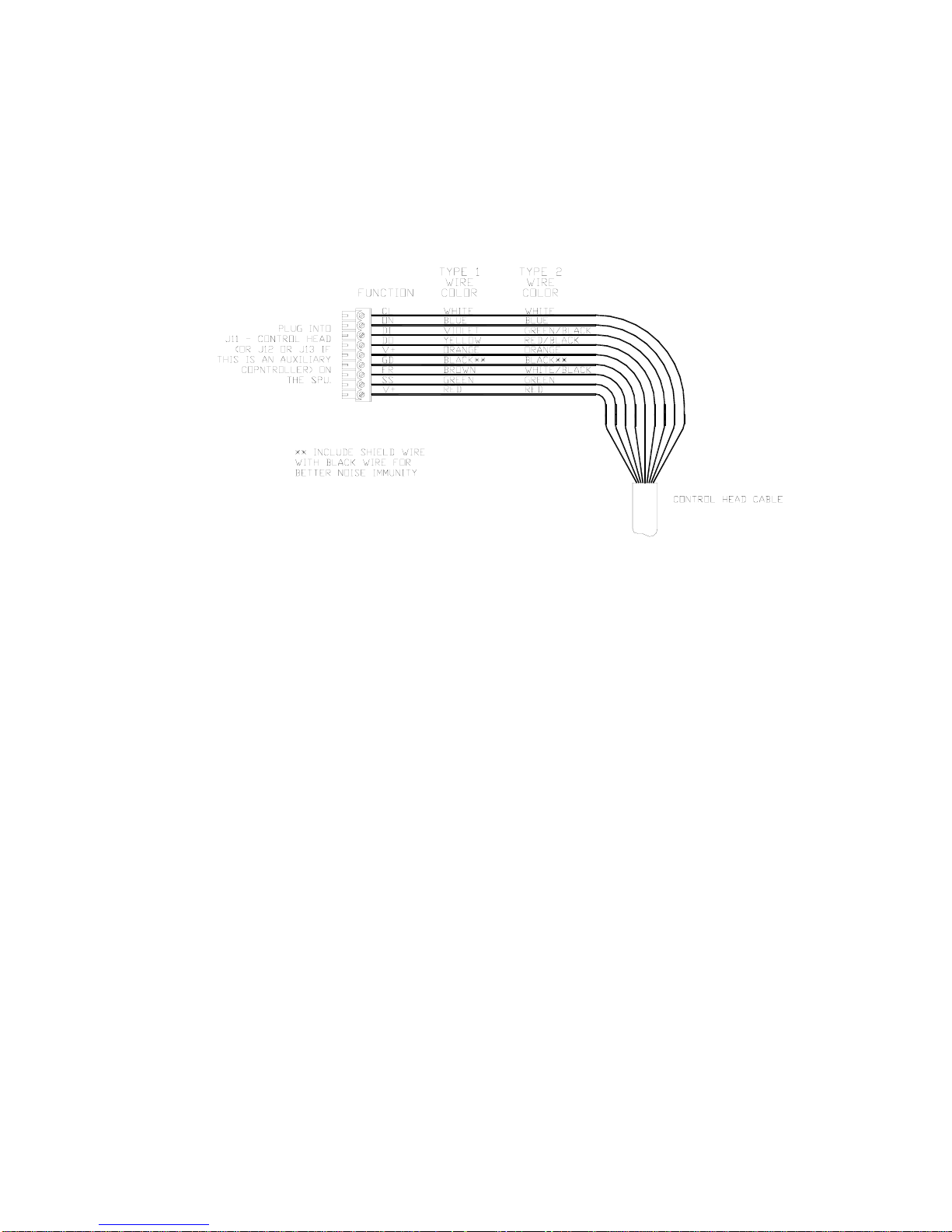
ComNav Commander P2 Installation & Operation Installation
Input & Output Connections
Control Head
Two types of control cable are used in manufacturing Commander P2 systems. The only
difference between them is the colour-coding of the wires. Wire the cable from the main
Control Head onto the nine-position plug-in connector according to the following diagram:
Figure 34 – Wiring Connections for Control Head, Handheld Remotes, and Fixed Remotes.
Plug the nine-position plug-in connector into the SPU receptacle labelled
- CONTROL HEAD.
J11
Auxiliary Controller(s)
All Control Heads, Handheld Remotes, and Fixed Remotes designed to work with the
Commander P2 Advanced Autopilot system utilize the same wiring diagram as the Main
Control Head. See Figure 34, above. The only difference is that these devices are plugged
into the receptacles J12
Note: Auxiliary Head Power On/Off
The Commander P2 SPU is shipped from the factory configured so that
power can only be turned on or off from the Main Control Head. The
Main Control Head is designated as the Head which is plugged into the
SPU receptacle labelled J11
However, the Commander P2 system can also be configured so that it
can be turned on or off by any Control Head plugged into the receptacles
J12 - A
UX 1 or J13 - AUX 2 (note: power cannot be turned on from
CR-203 or TS-203 Remotes). If reconfiguration is desired, follow the
instructions for enabling Auxiliary Head / Remote Power On (see page
173).
- AUX 1 or J13 - AUX 2 instead of J11 - CONTROL HEAD.
- CONTROL HEAD.
Document PN 29010074 V3.1 - 60 -
Page 61
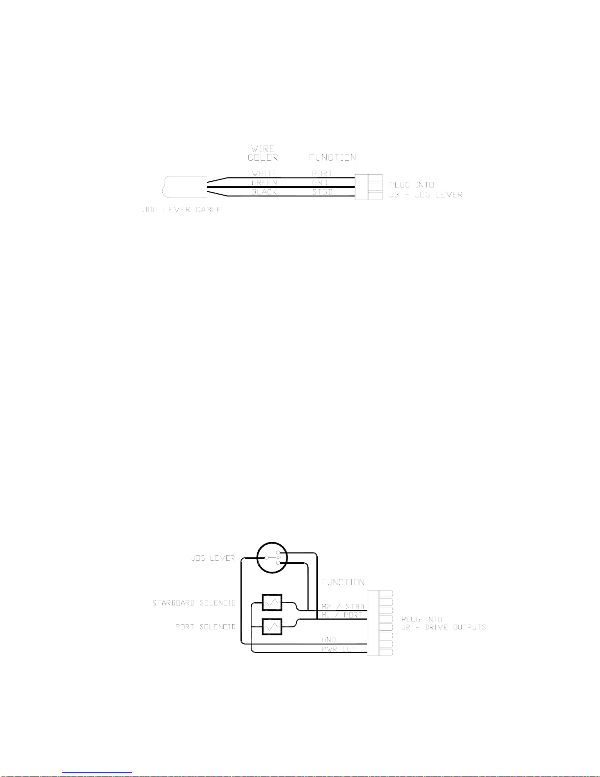
ComNav Commander P2 Installation & Operation Installation
Jog Levers
Any number of Non-Follow-Up (NFU) Jog Levers can be connected to the Commander P2
SPU. They are simply wired in parallel to each other. Connect them to the terminal labelled
J3 - JOG LEVER as per the following diagram:
Figure 35 – Wiring Connections for Jog Levers
In order to use the Jog Levers connected in the above manner, the autopilot must be turned
on. The autopilot will then move the rudder either port or starboard for as long as the Jog
Lever is held activated. However, the autopilot will stop the rudder when it gets to the
(user-adjustable) rudder limits programmed into the autopilot. This reduces stress on the
steering system.
Four-Way Valves, Used with Jog Levers
If the Commander P2 is being used with four-way solenoid-activated valves (see page 67), it
is also possible to wire Jog Levers so that they may be used even when the autopilot is not
powered on.
Caution! This configuration is NOT RECCOMMENDED. It is possible to
damage the drive output circuits in the SPU when this configuration is
used, which may void the warranty on your Commander P2 system,
and/or the warranty of other equipment.
Also, in this configuration, the Jog Levers will force the rudder hard-over
to the physical stops, and keep pushing for as long as any Jog Lever is
activated. This may cause a hydraulic seal to blow, and/or damage the
rudder mechanism.
Bearing in mind the cautions above, if you wish to be able to use Jog Levers to activate
Four-Way Valves with the autopilot powered off, this is the wiring connection for it:
Figure 36 – Wiring Connections for Four-Way Valves with Jog Levers
Document PN 29010074 V3.1 - 61 -
Page 62
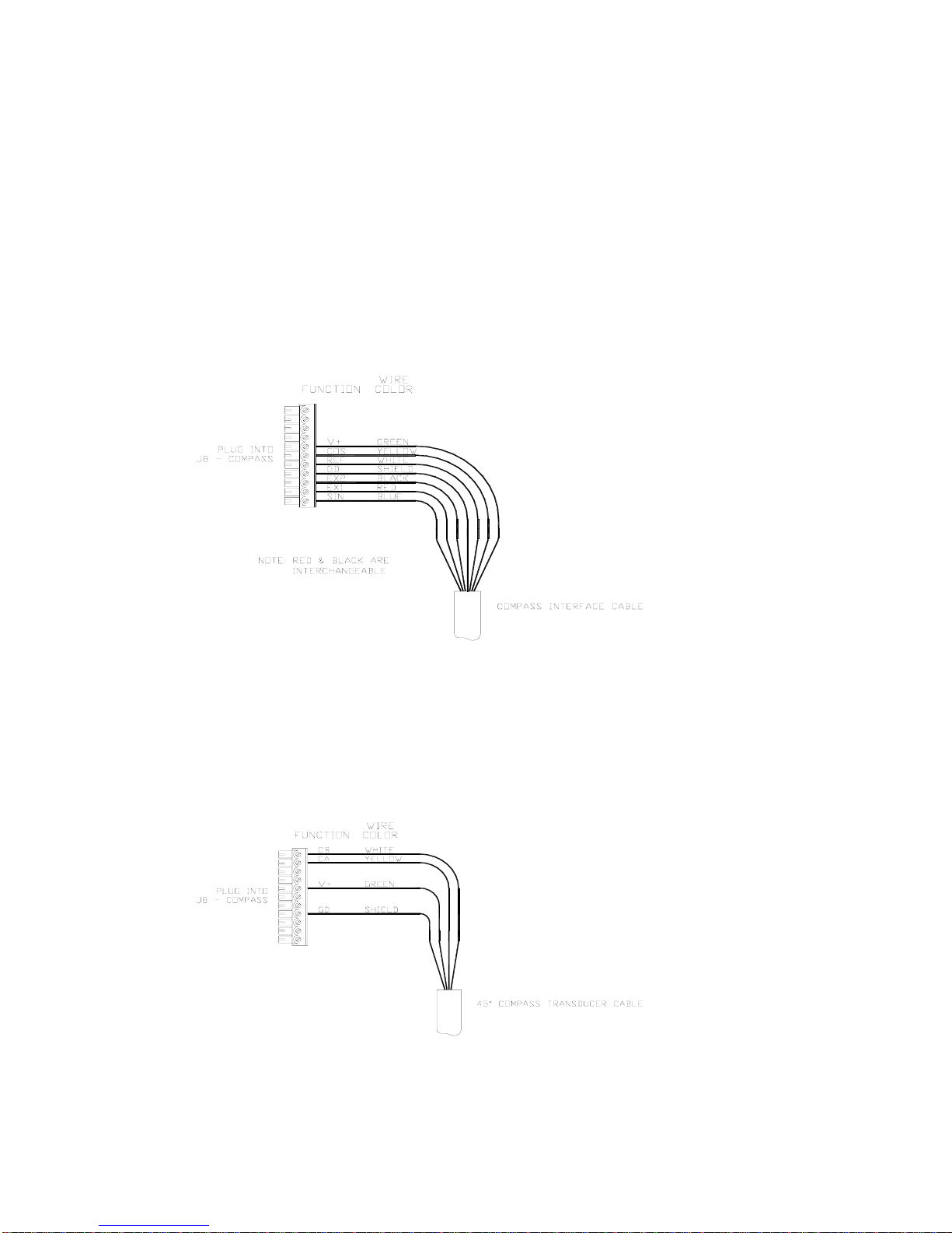
ComNav Commander P2 Installation & Operation Installation
Compasses
All compasses, other than NMEA 0183 compasses, are connected to the SPU receptacle
labelled J8 – C
If you ordered your Commander P2 system with a ComNav Fluxgate Compass (with or
without the optional Heading Rate Stabilizer), a short Compass Interface Cable
(PN 31110024) will have been supplied with the system. Plug this interface cable onto the
cable coming from the Fluxgate Compass (or the Heading Rate Stabilizer), and then wire the
other end into the eleven-position plug which mates with the J8 receptacle, as per the
following diagram.
If you ordered your system with the Magnetic Sensor, and mounted it on the bottom of your
magnetic compass, wire the flying-lead end of the sensor cable as per the following diagram.
If you mounted the sensor of top of the compass, exchange the blue & yellow wires.
OMPASS (see page 73 for how to connect NMEA compasses).
Figure 37 – Wiring Connections for Analog Compasses
If you have a 45° Compass Transducer with your Commander P2 SPU, it is also connected
to the eleven-position plug that fits into the J8 receptacle. Wire as per the following diagram.
Note: more than one wire will fit into the V+ and GND connections, so you can connect
a 45° Compass Transducer and an analog compass at the same time. You may then
select either as the “Compass Source” (see page 112) at any time during operation.
Figure 38 – Wiring Connections for 45° Compass Transducer
Document PN 29010074 V3.1 - 62 -
Page 63
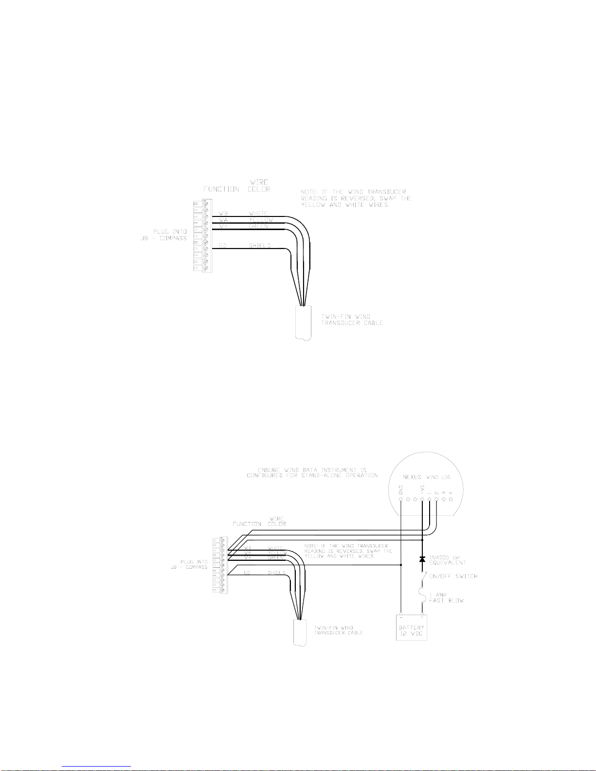
ComNav Commander P2 Installation & Operation Installation
Wind Transducer
If you are connecting a ComNav Twin-Fin Wind Transducer to the Commander P2 SPU, it
must also be connected to the eleven-position plug that fits into the J8
Wire as per the following diagram.
Note: more than one wire will fit into the V+ and GND connections, so you can connect a
Wind Transducer and an analog compass and/or a 45° Compass Transducer, all at the same
time.
– COMPASS receptacle.
Figure 39 – Wiring Connections for Twin-Fin Wind Transducer
If your vessel is equipped with a ComNav NX2 Wind Data Instrument (PN 20620050) or an
Classic Nexus or NX2 Network System (various PNs), you can use the Wind transducer with
both the Commander P2 autopilot and the Instrument or System, either individually or at the
same time, by wiring it up as shown in one of the following diagrams.
Figure 40 – Wind Transducer with NX2 Wind Data Instrument
Document PN 29010074 V3.1 - 63 -
Page 64
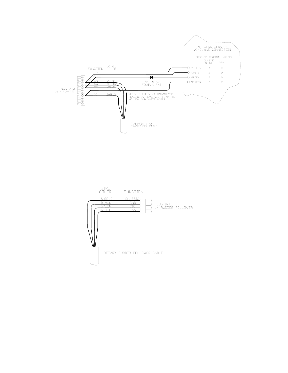
ComNav Commander P2 Installation & Operation Installation
Figure 41 – Wind Transducer with Classic Nexus or NX2 Network Server
Rudder Follower
The Rudder Follower is connected to the four-position receptacle on the SPU labelled
– RUDDER FOLLOWER. Wire the Rudder Follower to the plug-in connector as per the
J4
following diagram.
Figure 42 – Wiring Connections for Rudder Followers
Document PN 29010074 V3.1 - 64 -
Page 65
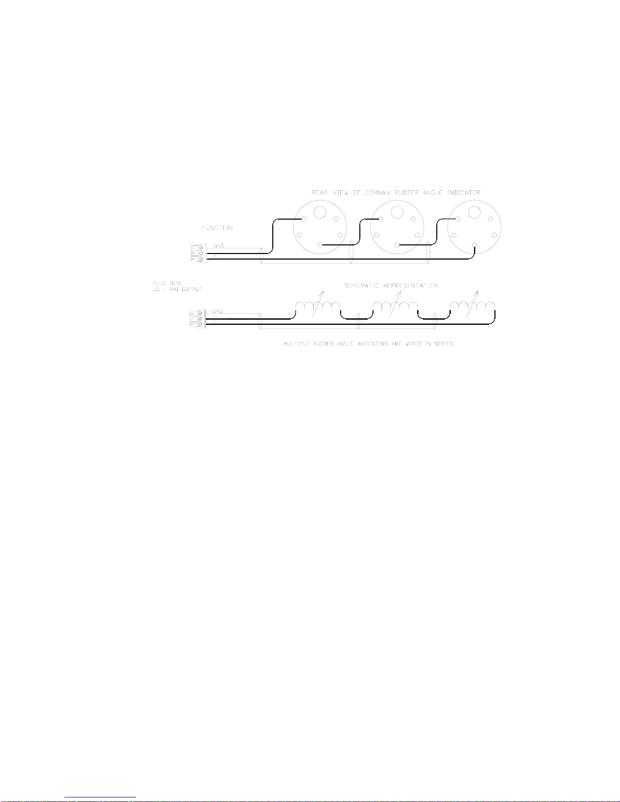
ComNav Commander P2 Installation & Operation Installation
Rudder Angle Indicators
The Commander P2 system will drive up to five 500 microampere Rudder Angle Indicator
(RAI) meters – such as those supplied by ComNav (PN 20360014). Mounting instructions
are included with each meter. Wire the meter to the plug for the SPU receptacle labelled
J5 – RAI
as shown below:
OUTPUT. If you have more than one RAI meter, they should all be wired in series,
Figure 43 – Wiring Connections for Rudder Angle Indicators
Document PN 29010074 V3.1 - 65 -
Page 66
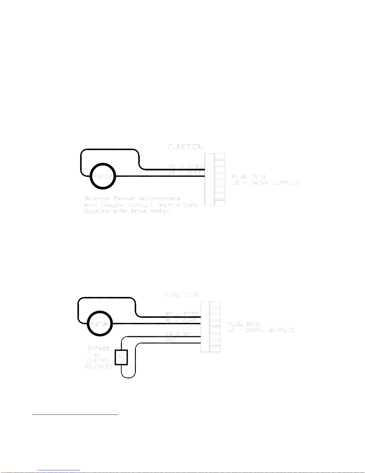
ComNav Commander P2 Installation & Operation Installation
Drive Outputs
The Commander P2’s SPU is capable of directly driving a variety of steering systems.
Optional Drive Boxes are available for those systems not handled directly by the Commander
P2. Contact your ComNav Dealer for more information.
Reversing DC Motor Hydraulic Systems
The Commander P2 SPU can directly handle reversing DC motor hydraulic2 pumps drawing
up to approximately 20 amps. For larger current requirements, the ComNav CT2 Drive Box
should be used. To connect the pump motor directly to the SPU, use the following diagram.
Note that wire polarity is not important, since the Commander P2 will automatically make the
necessary adjustments internally when the system is set up.
Figure 44 – Wiring Connections for Reversing DC Motors
Linear Actuators or Mechanical Rotary Drives
Some Linear Actuators incorporate a Bypass Valve. To operate properly, the Bypass Valve
should be activated by the SPU’s SW’D
incorporate a solenoid-activated clutch. The clutch solenoid should also be activated by the
B+ output. Refer to the following diagram:
SW’D
B+ output. Similarly, most mechanical drives
Figure 45 – Wiring Connections for Linear Actuators or Mechanical Rotary Drives
2
Two very important steps when installing any hydraulic system are to bleed it of any air trapped in the fluid, and to check
for fluid leaks. These will be done later – see pages 77 and 95.
Document PN 29010074 V3.1 - 66 -
Page 67
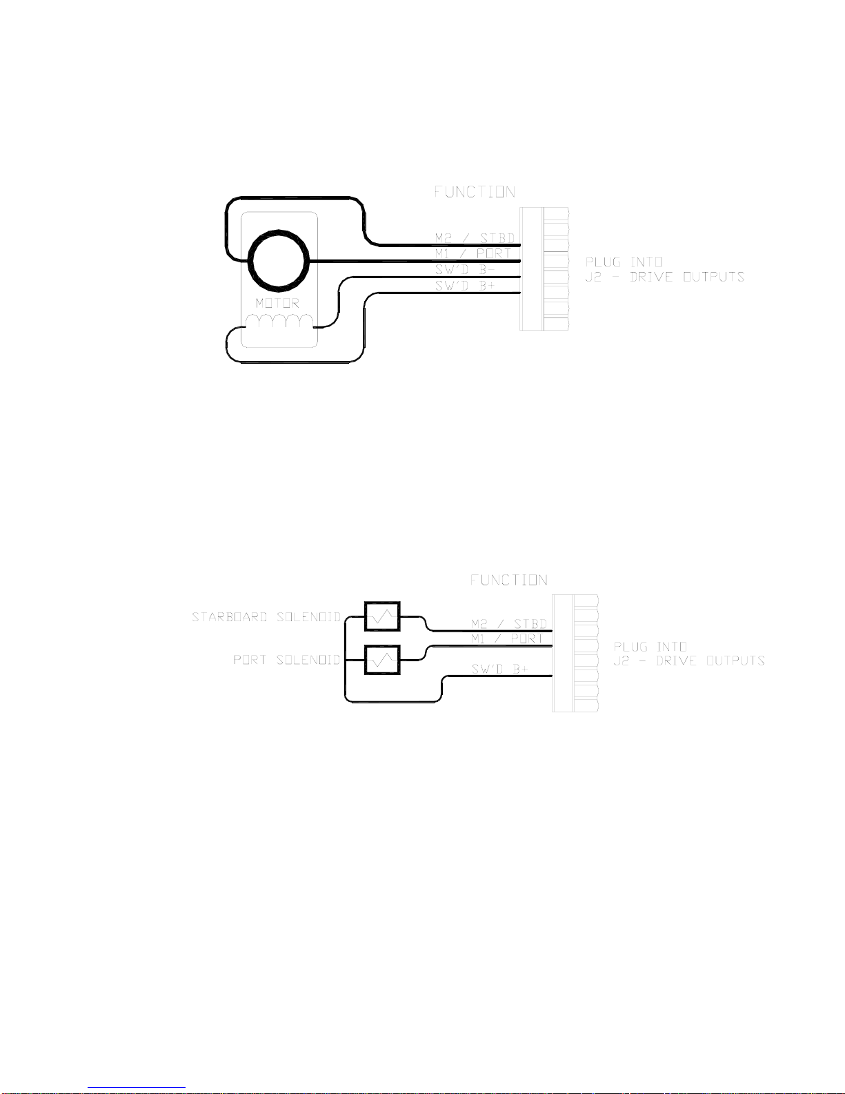
ComNav Commander P2 Installation & Operation Installation
Shunt-Field Reversing Motors
For shunt-field reversing motors, connect the shunt field coil positive terminal to SW’D B+
and the coil negative terminal to SW’D
Figure 46 – Wiring Connections for Shunt Field Reversing Motors
GND as per the following diagram:
Standard Four-Way Solenoid-Activated Hydraulic Valves
Connection to 12 VDC or 24 VDC solenoids should be made as per the following diagram.
In this configuration, the autopilot supplies the positive voltage (SW’D
autopilot is in POWER STEER, AUTO, or NAV modes. SW’D
B+ is turned off in STANDBY
B+) whenever the
mode, thus providing an extra measure of safety.
Figure 47 – Wiring Connections for Standard Four-Way Solenoid Valves
Note: wiring of Jog levers directly to standard 4-way valves is possible.
However, doing so is NOT RECCOMMENDED. See the description of
the proper way to wire Jog Levers, on page 61.
Document PN 29010074 V3.1 - 67 -
Page 68
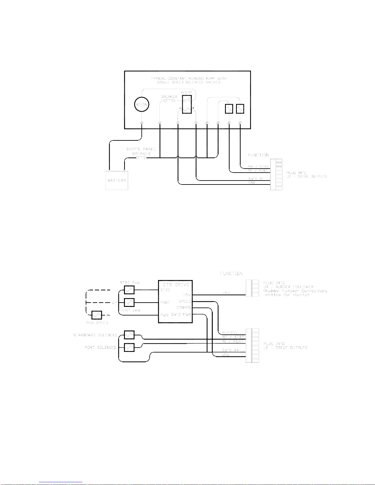
ComNav Commander P2 Installation & Operation Installation
The above diagram assumes that an engine driven pump is used for the
hydraulic system. In the case of an electrically powered constant
running pump, use the following connection:
Figure 48 – Wiring Connections for Constant Running Electric Pump.
Two-Speed Solenoid Valves
ComNav’s CT5 Drive Box (PN 20350004) should be used to interface between the
Commander P2 SPU and two-speed solenoid systems. Connect the CT5 to the SPU as per
the instructions shipped with the CT5, and the following diagram:
Figure 49 – Wiring Connections for Two-Speed Solenoid Valves
Document PN 29010074 V3.1 - 68 -
Page 69
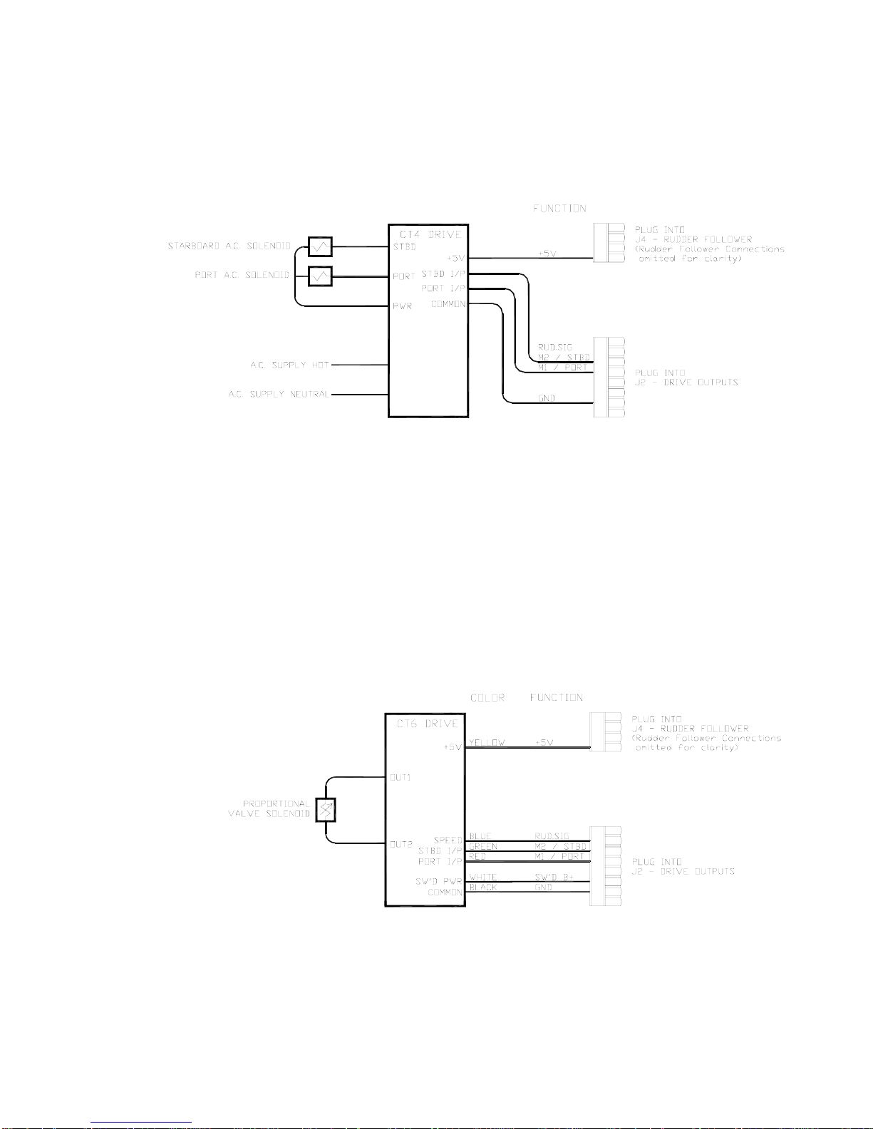
ComNav Commander P2 Installation & Operation Installation
A.C. Solenoids
ComNav’s CT4 Drive Box (PN 20350003) should be used to interface between the
Commander P2 SPU and A.C. solenoid systems. Connect the CT4 to the SPU as per the
instructions shipped with the CT4, and the following diagram:
Figure 50 – Wiring Connections for A.C. Solenoids
Proportional Solenoid Valves
ComNav’s CT6 Drive Box (PN 20350005) should be used to interface between the
Commander P2 SPU and proportional valves. The CT6 is custom configured to match the
requirements of the particular valve it is to be fitted to.
Please note: ComNav’s Production Department requires information about the make and
model of the proportional valves, in order to correctly configure the drive box.
Instructions for connecting the CT6 to proportional valves are shipped with the CT6 unit.
Connection between the CT6 and the Commander P2 SPU should be made as per the
following diagram.
Figure 51 – Wiring Connections for Proportional Solenoid Valves
Document PN 29010074 V3.1 - 69 -
Page 70
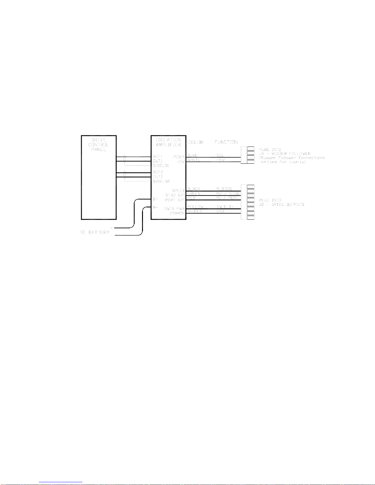
ComNav Commander P2 Installation & Operation Installation
Azimuth Drives, Surface Piercing Drives and Jet Drives
Newer models of these types of drives are often supplied with an electronic Autopilot
Interface, to which the Commander P2 SPU can directly connect.
Older versions of these drives, however, may require the fitting of ComNav’s one or
two-channel Isolation Amplifier (PN 20350006 and 20350007, respectively). Instructions for
connecting the Isolation Amplifier to the steering system are shipped with the Amplifier.
Connection between the Isolation Amplifier and the Commander P2 SPU should be made as
per the following diagram.
Figure 52 – Wiring Connections for Isolation Amplifiers
The ComNav CT7 Thruster Interface (see page 40) can also be used with some of these
types of drives. See the CT7’s Installation & Operation Manual for wiring instructions.
Document PN 29010074 V3.1 - 70 -
Page 71
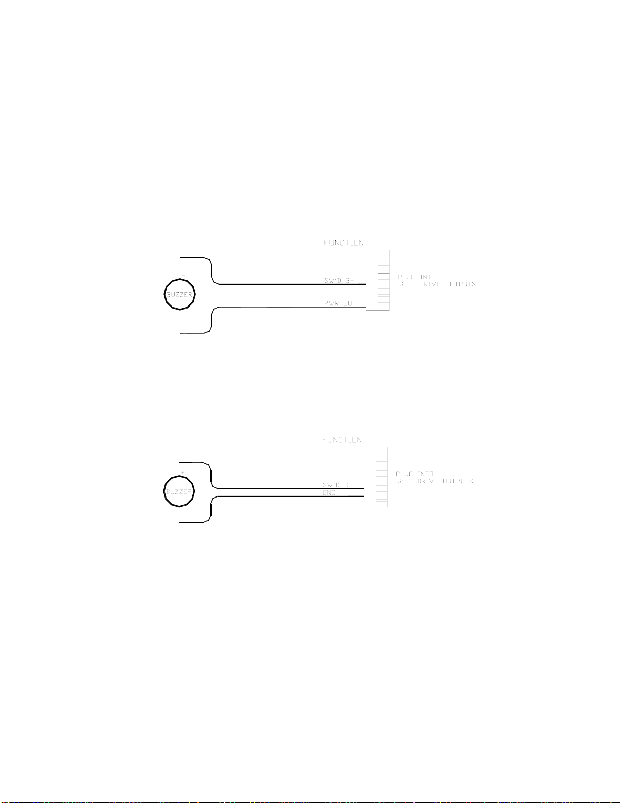
ComNav Commander P2 Installation & Operation Installation
External Alarm Output
An external alarm can be connected to the Commander P2 SPU. The autopilot can be
configured to activate the external alarm whenever an alarm or error message appears on
the Control Head. You can modify the configuration to activate the external alarm only if the
Watch Alarm is not answered (as opposed to activating it for all alarms). See the description
of the Alarm O/P (Alarm Output) parameter on page 88 for information on how to choose
these options.
One of two outputs can be used for the external alarm. Typically, you would choose to
connect the external alarm between Battery Positive (PWR OUT) and the Switched B- (SW’D
B-) outputs on J2, as in the following diagram:
Figure 53 – External Alarm, using SW'D B- Output
Alternatively, you may choose to use the SW’D B+ and GND outputs as shown here:
Figure 54 – External Alarm, using SW'D B+ Output
Note: when using the External Alarm configuration shown in Figure 53,
there is a small current which will be flowing constantly between the pins,
even when the alarm is OFF. This will not be a problem with many types
of alarms; however, with certain types of sensitive Piezo-electric audible
alarms, the leak current can cause a constant low-level tone from the
Piezo device.
An Application Note is available which describes this potential problem in
detail, with suggested remedies. The Note also lists a number of Piezo
alarms which are known to work well with Commander P2 system.
Please ask your ComNav Dealer (or go to ComNav’s web site) for
Application Note 2007-01.
Document PN 29010074 V3.1 - 71 -
Page 72
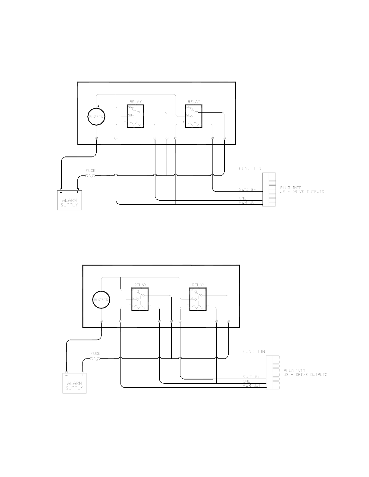
ComNav Commander P2 Installation & Operation Installation
Some installations require separate monitoring for power failures. This can be accomplished
with the following circuit, which utilizes two relays. The coil voltage of the relays should
match the supply voltage for the autopilot. The Alarm Supply, which must be a separate,
dedicated supply from the autopilot supply, should match the voltage of the alarm.
Figure 55 – External Alarm, SW'D B- Output – with Power Fail Option
The alternative circuit, using Switched B+ as the alarm output:
Figure 56 – External Alarm, SW'D B+ Output – with Power Fail Option
Document PN 29010074 V3.1 - 72 -
Page 73
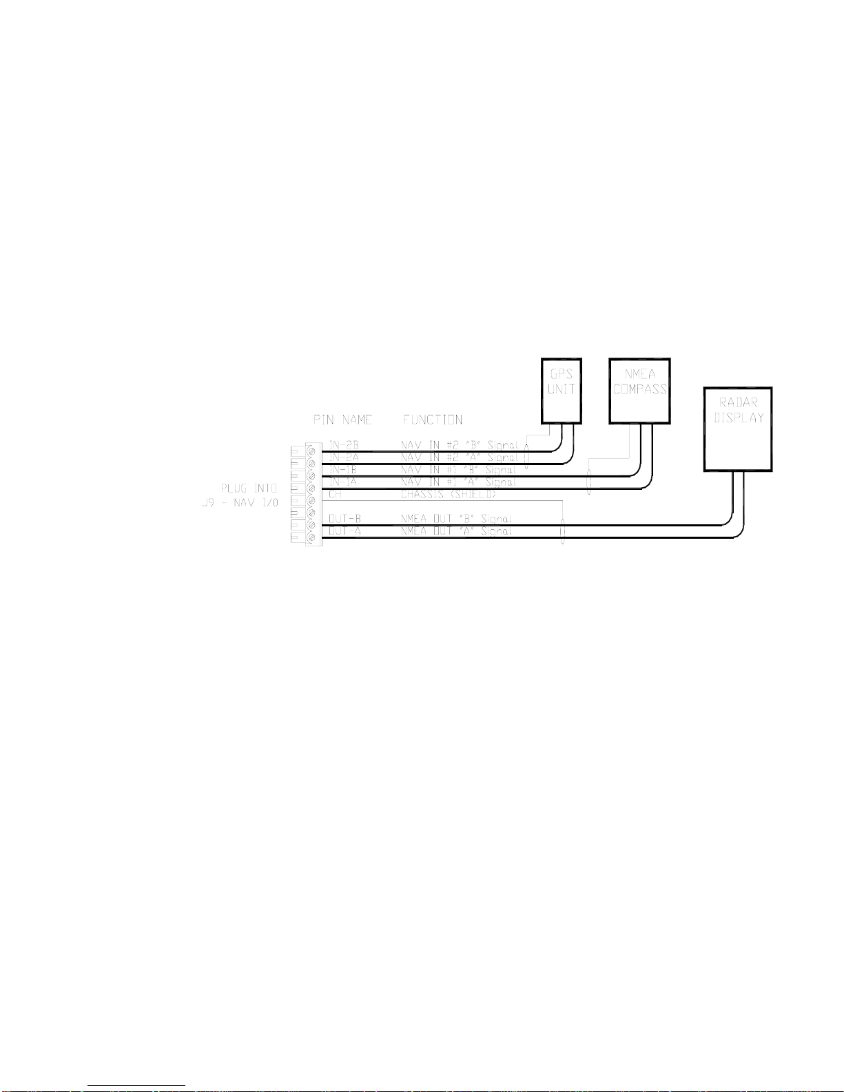
ComNav Commander P2 Installation & Operation Installation
NMEA 0183 Input & Output
The Commander P2 has ability to accept digital information formatted according to the
NMEA 0183 standard. Many marine electronics devices – such as digital compasses, GPS
receivers, chartplotters, and electronic charting systems, to name a few – have outputs
complying with NMEA 0183.
Two such devices can be connected directly to the Commander P2 SPU, by wiring them into
the plug mated to the receptacle labelled J9
The Commander P2 SPU also has an NMEA output, to allow the autopilot’s real-time
Heading data to be sent to devices such as radar, a chart plotter or a navigation program on
a PC.
The diagram below shows typical wiring for the J9 connector.
– NAV I/O.
Figure 57 – Typical NMEA 0183 Connections
When the autopilot is turned on, the Status LED labelled NMEA 0183
Diagnostic section will be lit whenever the autopilot is receiving data on the N
IN #1 in the SPU’s
AV1 input. Note
that this indicator only shows that data was received. It does not mean that the data received
is valid.
Typically, this LED will flash at a rate of about once per second for regular data from a GPS
or Chartplotter. It will typically flash at a rate of about ten times per second when connected
to a heading source such as the Vector G2 GPS Compass. If the LED does not flash, and
you are sure the sending device is in fact sending data, try reversing the wires connected to
AV1 - IN.
N
Similarly, the LED labelled NMEA 0183
data on the N
AV2 input. If the LED does not flash and you are sure the sending device is
sending data, try reversing the two wires connected to N
IN #2 will be lit whenever the autopilot is receiving
AV2 - IN.
Refer to Appendix 1 for more information on the NMEA 0183 sentences accepted and sent
by the Commander P2 system.
Document PN 29010074 V3.1 - 73 -
Page 74
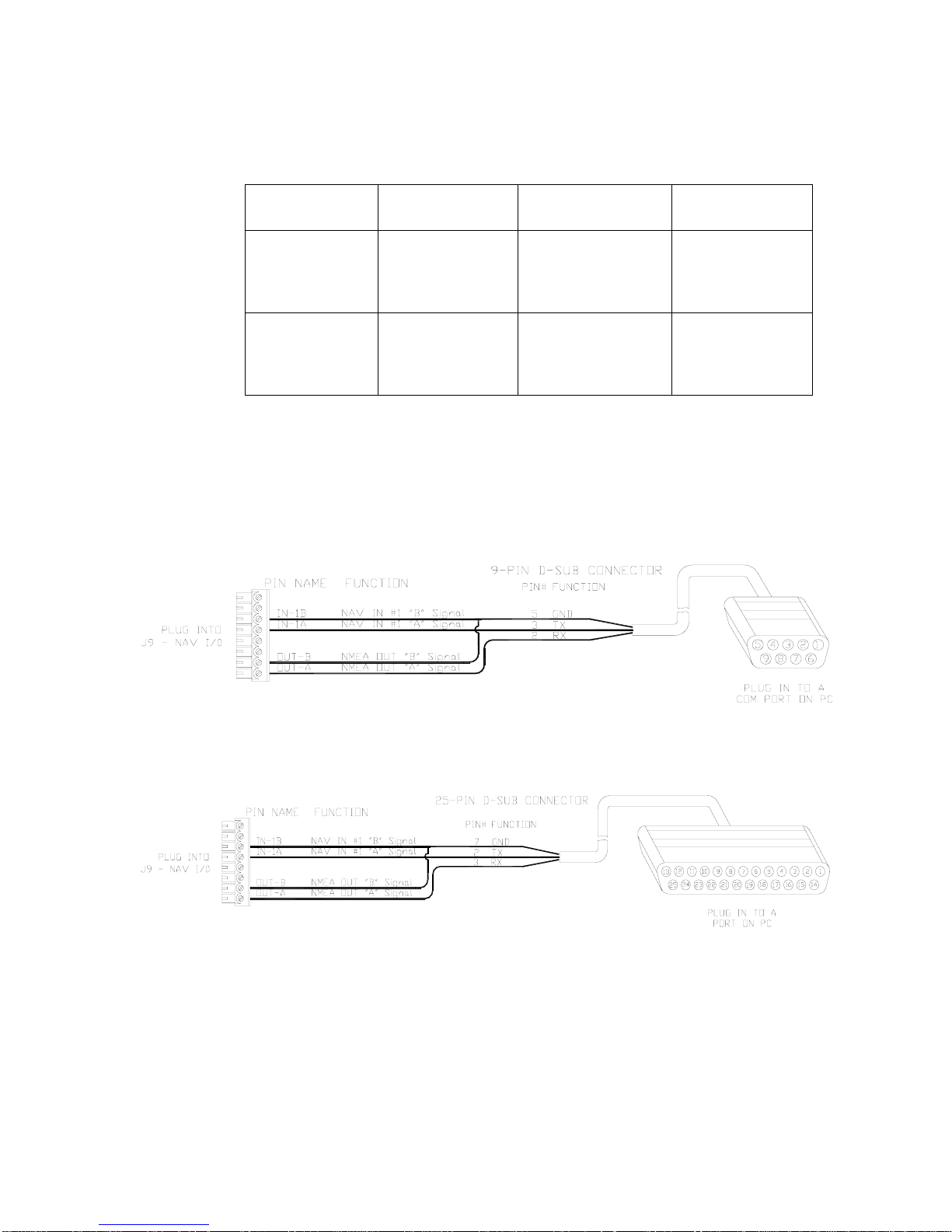
ComNav Commander P2 Installation & Operation Installation
Other manufacturers may have used different names, for the NMEA 0183 serial data lines,
than those used by ComNav. Refer to the following table for some typical equivalents:
ComNav Name J9 Connector
‘A’ signal
‘B’ signal
Table 2 – NMEA Signal Translation Guide
PC Input & Output
The Commander P2 system can be connected to a desktop or laptop Personal Computer
which is running navigation software. The following diagrams show how to do this:
Label
1A
IN or 2A IN
A
OUT
1B
IN or 2B IN
OUT
B
Function Alternative
Names
Negative voltage
with respect to ‘B’
should produce a
logical 1 (mark)
Negative voltage
with respect to ‘A’
should produce a
logical 0 (space)
+ or NMEA
SIG or S
POS or +
- or NMEA
RTN or R
NEG or -
+
IGNAL
VE
-
ETURN
VE
Figure 58 – Connection to a PC with a DE-9 Connector
Figure 59 – Connection to a PC with a DB-25 Connector
Note: this method mixes the RS-232 electrical levels of a PC’s COM port with the RS-422
levels of the SPU’s NMEA 0183 NAV ports. Nonetheless, this method usually works fine.
⇔
However, should you encounter any problems, RS-232
RS-422 Convertors are available.
Contact your ComNav Dealer for details.
Document PN 29010074 V3.1 - 74 -
Page 75

ComNav Commander P2 Installation & Operation Installation
Other Connections
Miscellaneous I/O
The J6 – MISCELLANEOUS 3 connector is reserved for possible future use. The receptacle is
supplied with a 10-pin mating plug.
Thruster Interface
The J7 – THRUSTER I’ FACE connector is used with the CT7 Thruster Interface. The
receptacle is not supplied with a mating plug, since the required plug is supplied with the
CT7.
ComNav Network
The J10 – COMNAV NETWORK connector is reserved for possible future use. The receptacle
is not supplied with a mating plug.
3
This connector was labelled J6- ENGINE I’ FACE in earlier Commander P2 SPUs.
Document PN 29010074 V3.1 - 75 -
Page 76

ComNav Commander P2 Installation & Operation Installation
Post-Installation Checks
Be sure to perform all of the Electrical and Hydraulic checks listed below before using the
Commander P2 Advanced Autopilot System for the first time.
Electrical Checks
Once you have completed the wiring of the Autopilot System, perform the following checks to
ensure that the installation is complete and that the autopilot has been installed in a safe and
secure manner.
1) Check the power supply wiring (from the battery/breaker). Verify that the polarity
and voltage are correct (use an accurate voltmeter for this). Also check for
correct wire size, tightness of all connections, fusing, and proper operation of the
battery power switch. Only after all checks are passed should you plug the
power plug into the JI
2) Check the connections from the compass to the SPU.
3) Check the connections from the Rudder Follower to the SPU.
4) Check that when the rudder is manually moved from full Starboard to full Port,
and vice-versa, the Rudder Follower has fully free movement and is not being
restricted in any way.
– BATTERY INPUT receptacle on the Signal Processor Unit.
5) Check the connection from the Control Head(s) to the SPU.
6) Check the connections to the drive equipment from the SPU.
7) Check that the cables are neatly placed and secured.
8) Ensure that extraneous materials (wire strands, etc) have been removed.
Route all the wires and cables sideways out from the SPU (to the left &/or right, as
appropriate). Use external tie-downs or cable grips to keep the wires & cables secure, with
no excess strain on them, or on the plugs that are mated to the SPU’s receptacles.
Carefully re-install the Wiring cover on the SPU. Be sure not to pinch any of the wires or
cables between the Wiring Cover and any other part of the SPU. Secure the Wiring Cover
with the two knurled thumb-nuts.
Document PN 29010074 V3.1 - 76 -
Page 77

ComNav Commander P2 Installation & Operation Installation
Hydraulic Checks
1) After installing the autopilot system, check to ensure that your manual steering system is still
fully functional. Be sure to individually check each steering station on the vessel.
2) Check that when turning the steering wheel to starboard, the rudder actually moves so as to
turn the vessel to starboard.
3) Check that when the steering wheel is turned to port, the rudder moves so as to turn the
vessel to port.
4) If you have installed a ComNav Marine Reversing Motor Pump, a Constant Running Pump or
an Engine Driven Pump:
⇒ During the first few weeks of usage, check for residual air and leaking fittings in order to
prevent poor or dangerous steering performance.
Residual air in the steering system
Following the initial installation and bleeding of any hydraulic pump, some residual air may
remain suspended in the hydraulic oil. During the first few weeks, this air will gradually bleed
out through the header tank or the highest helm pump and the oil level may go down. Check
the fluid level several times during this period, and add more oil as required.
Leaking fittings or equipment
Following the initial installation and bleeding of a hydraulic pump, continuously monitor the oil
level at the reservoir, or the highest helm pump in your steering system, and add oil if
required. If you find that you are often adding oil, it may be an indication of leakage in your
steering system. Check all hydraulic steering fittings and equipment for leakage.
Document PN 29010074 V3.1 - 77 -
Page 78

ComNav Commander P2 Installation & Operation
Document PN 29010074 V3.1 - 78 -
Page 79

ComNav Commander P2 Installation & Operation
Getting Started
Document PN 29010074 V3.1 - 79 -
Page 80

ComNav Commander P2 Installation & Operation
Document PN 29010074 V3.1 - 80 -
Page 81
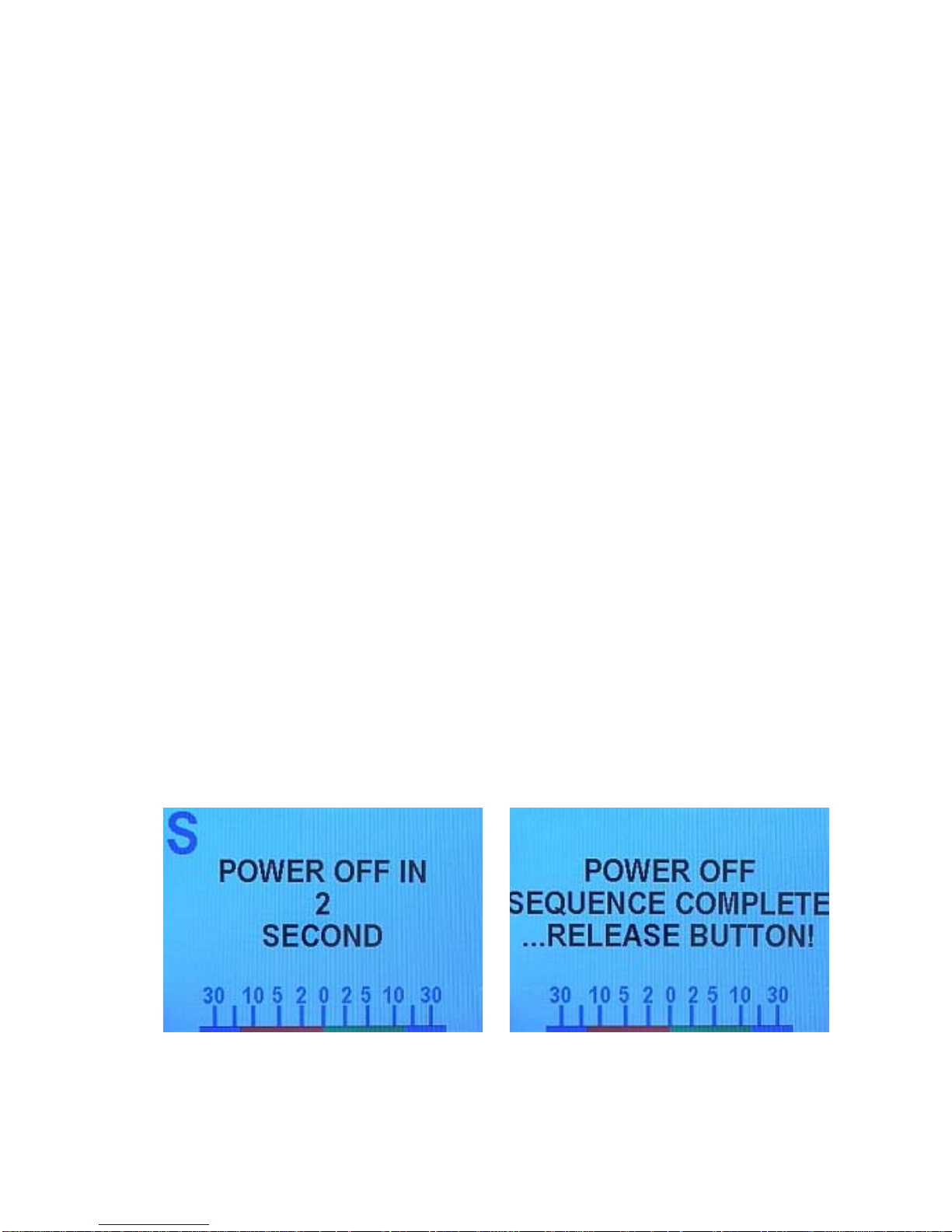
ComNav Commander P2 Installation & Operation Getting Started
Getting Started
This chapter describes all the basic concepts you need to be familiar with when using your
Commander P2 Advanced Autopilot System, and the steps needed to prepare it for use.
Autopilot Operations
After it is installed, almost all of your interaction with your autopilot system will be done by
means of the Control Head:
• selecting an operating mode
• setting up the parameters you wish to use in each mode
• monitoring your vessel’s Heading
• setting a desired Heading to be followed
• making Special Turns
• monitoring the various system status items
• and so on
Power On/Off
The first step in using your Commander P2 system is to turn it on …
To turn on the Commander P2 system, press & hold the Control Head’s red
STANDBY/ON/OFF button, until the introductory display (see Figure 61) appears, then
release the button.
The initial introductory display remains for a few seconds. Then, the software versions of
both the Control Head and the SPU are listed on the display, below the Commander P2 line
on the screen. You may find it helpful to record those version numbers, to refer to should
your Commander P2 System ever require servicing.
To turn off the Commander P2 (at any time), press and hold the red STANDBY/ON/OFF
button. The autopilot will switch first to STANDBY mode, if it was not already there.
But then, if you keep pressing the button, the autopilot will start a 3-second power-down
sequence. Once the countdown has expired, the display will prompt you to release the
STANDBY/ON/OFF button … and once you do, the whole autopilot system will immediately
shut off.
Figure 60 – Power Off Sequence
If you release the STANDBY/ON/OFF button before the 3-second countdown has completed,
the autopilot will abort the countdown, and remain in STANDBY mode.
Document PN 29010074 V3.1 - 81 -
Page 82
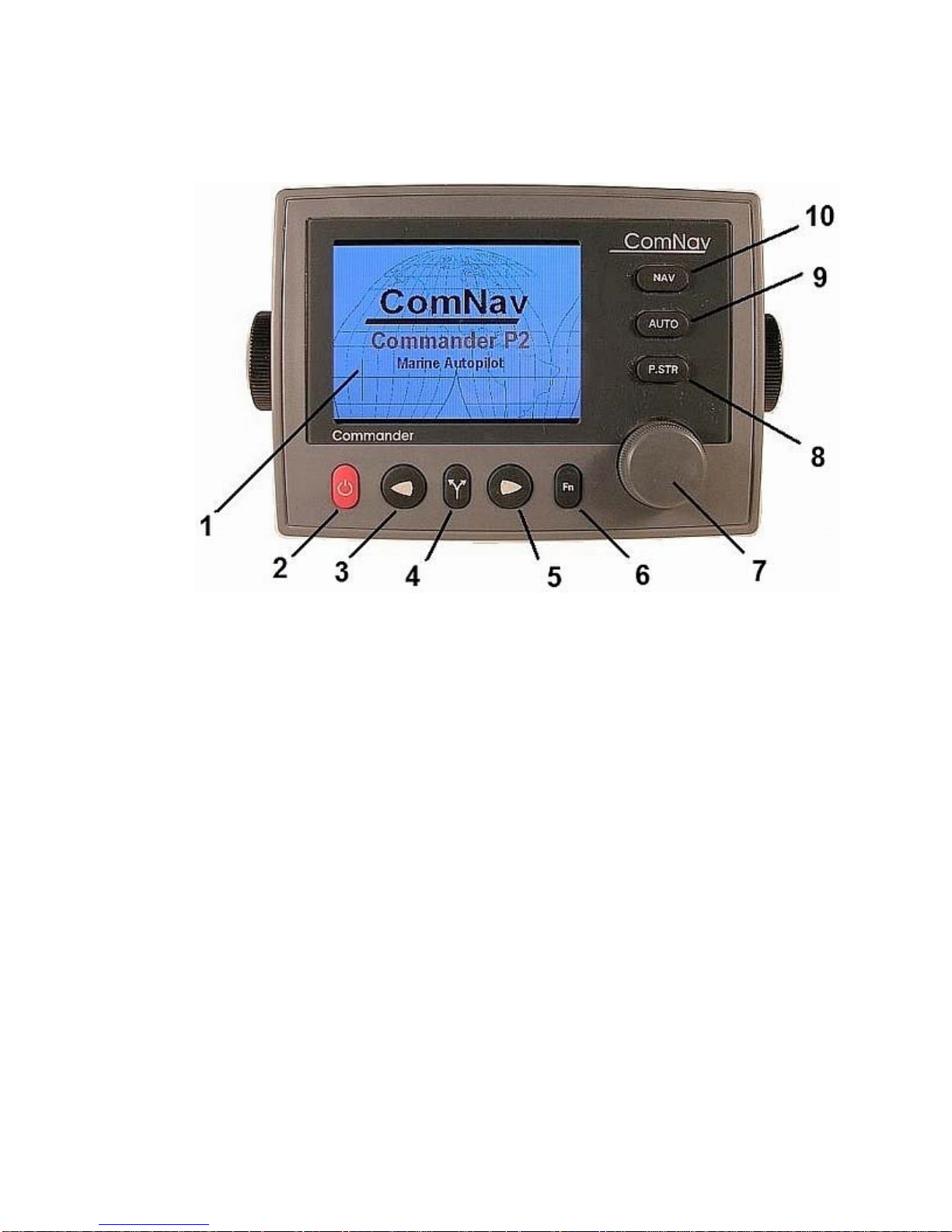
ComNav Commander P2 Installation & Operation Getting Started
Using the Control Head – LCD Screen & Buttons
Figure 61 – Using the Control Head
The elements of the Control Head (with reference to the identifiers above) are:
1) LCD Screen. As long as the Commander P2 system is powered on, the LCD
screen normally displays the compass heading, rudder angle, and mode of
operation; it can also be displaying desired heading, system status, other
information, and various menus. The overall set of items being displayed
changes in response to the various command buttons listed below (the screen
shown above is the initial screen, which appears for a few seconds after
Power On).
2) STANDBY/ON/OFF button. To power on the system, press and hold this button
until the LCD screen lights up (with the introductory display shown above), and
then release the button. The Commander P2 can always be put into STANDBY
mode, by pressing and holding this button for approximately ½ second; it always
powers up in STANDBY mode. While in STANDBY mode, the autopilot will not
exert any control over your vessel. This button will also turn off the autopilot
when pressed and held for approximately 2 seconds. During regular operation,
double-pressing this button brings up (or cancels) the Standby menu.
3) PORT ARROW button. Pressing and maintaining this button while in POWER
STEER mode moves the rudder to port for as long as the button is held.
Pressing and maintaining this button while in AUTO, NAV, WORK or WIND
modes allows you to avoid obstacles in the vessel’s path, by turning to port.
Releasing the button automatically recovers your original Heading, Track or Wind
Angle.
Document PN 29010074 V3.1 - 82 -
Page 83

ComNav Commander P2 Installation & Operation Getting Started
4) TURN button. Pressing this button once while in AUTO or WORK modes
queues the default pre-programmed turn; in WIND mode, it queues a Tack or
Gybe turn. Subsequent presses of the TURN button scroll through all of the
available turn-types. The pre-programmed turn sequence is then initiated by
pressing either the PORT or STARBOARD ARROW button to indicate the
direction in which the turn will be executed. See Default Turn on page 112 for
more details on setting the default turn from the Special Turns available.
5) STARBOARD ARROW button. Pressing and holding this button while in
POWER STEER mode moves the rudder to starboard for as long as the button is
held. Pressing and maintaining this button while in AUTO, NAV, WORK or
WIND modes allows you to avoid obstacles in the vessel’s path, by turning to
starboard. Releasing the button automatically recovers your original Heading,
Track or Wind Angle.
6) FUNCTION (Fn) button. This is a multi-function button:
• On all vessels except sailboats, this button invokes WORK mode while in
AUTO or NAV modes. Double-pressing the button will bring up (or
cancel) the Work mode menu.
• If the Commander P2 is installed on a sailboat, this button invokes WIND
mode while in AUTO mode. Double-pressing the button will bring up (or
cancel) the Wind mode menu.
• Pressing this button when an alarm condition occurs in the autopilot
suppresses the alarm.
• This button is also used during Dockside Setup to initiate the automatic
learning features of the autopilot.
7) COURSE CHANGE knob. This is used in several ways:
• In POWER STEER mode, one ‘click’ changes the rudder angle by
approximately ¾ of a degree. A quick spin moves the rudder
approximately 7 degrees.
• In AUTO mode, turning the knob one ‘click’ will change the commanded
course by 1 degree. A quick spin of the knob changes the course by 10
degrees.
• The knob is also used to change parameters in the various menus.
8) POWER STEER button. Pressing & holding this button places the autopilot into
POWER STEER mode. This mode allows you to steer the vessel by using the
COURSE CHANGE knob, or by pressing and holding the PORT or STARBOARD
ARROW buttons. A double-press of this button brings up (or cancels) the Power
Steer mode menu.
9) AUTO button. Pressing & holding this button places the autopilot into AUTO
mode, and then the autopilot will automatically control your vessel’s steering
system so as the keep the vessel on the Heading that you select with the
COURSE CHANGE knob. Obstacles can be avoided by using the PORT and/or
STARBOARD ARROW buttons. A double-press of this button brings up (or
cancels) the Auto mode menu.
10) NAV button. Pressing & holding this button places the autopilot into NAV mode,
and then the autopilot will steer your vessel from NMEA 0183 data provided by a
GPS, Chartplotter, or some other compatible Navigation System. A double-press
of this button brings up (or cancels) the Nav mode menu.
Document PN 29010074 V3.1 - 83 -
Page 84
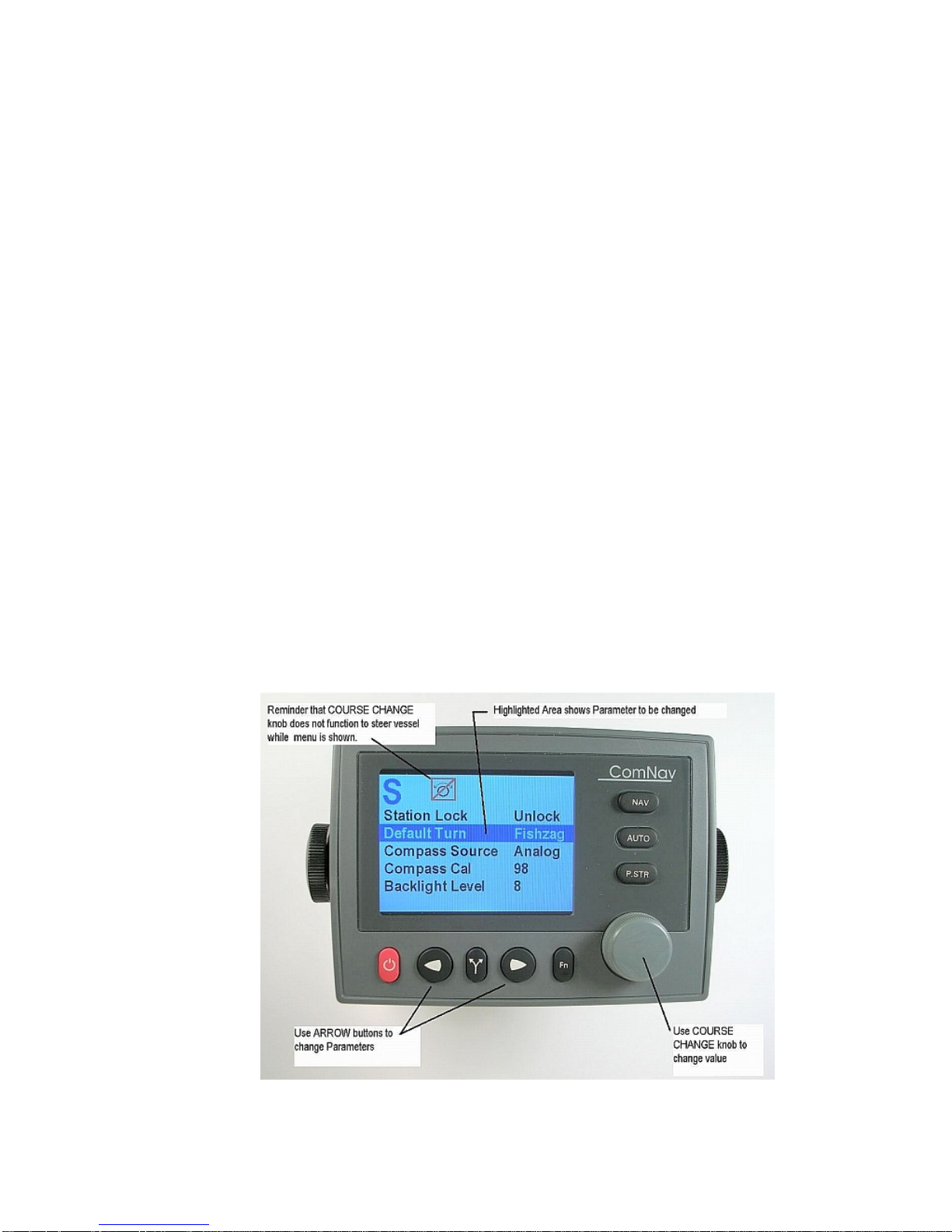
ComNav Commander P2 Installation & Operation Getting Started
Operating Modes & Menus
Your ComNav Commander P2 Advanced Autopilot System has four basic operating modes,
known as STANDBY, POWER STEER, AUTO, and NAV; a fifth operating mode, known as
WORK, is a sub-mode of AUTO & NAV modes, and is available on all vessel types except
sailboats. An alternative fifth mode, available only on sailboats, is known as WIND, and is a
sub-mode of AUTO mode.
Each of these modes has its own set of parameters that you can adjust, to configure and
fine-tune how your Commander P2 system behaves in the respective mode. These
parameters are stored in the system’s non-volatile memory; you can view & change them
with the Control Head, via sets of menus that appear on the LCD screen.
There is one more menu, called Dockside Setup, which is used for setting up a number of the
parameters that are common to all the operating modes.
In total, there are six different menus. The menus of the four basic operating modes
(STANDBY, POWER STEER, AUTO, and NAV) are accessed by using the respective mode
buttons: the STANDBY/ON/OFF button, the POWER STEER button, the AUTO button, and
the NAV button. The
Fn button is used to access the WORK or WIND modes’ menus.
• To access a particular operating mode menu, double-press the button associated with
that menu (e.g., the NAV button for the NAV mode’s menu).
• To quit viewing a particular operating mode menu, double-press the associated button
again, or wait about 10 seconds. The display will then revert to the active display of
whatever mode the Commander P2 is operating in.
Using the operating mode menus is fully described in the related sections, later in this
manual; see the Basic Operations chapter for Standby Mode, Power Steer Mode, Auto
Mode , & NAV Mode (pages 111, 114, 116 & 120 respectively), and the Advanced
Operations chapter for WORK Mode (page 135) & WIND Mode (page 138).
Accessing & using the Dockside Setup Menu is described in the next section.
Figure 62 – A Typical Menu
Document PN 29010074 V3.1 - 84 -
Page 85

ComNav Commander P2 Installation & Operation Getting Started
All menus are arranged with parameter names on the left side of the screen, and the current
value for each parameter on the right side.
Note that in each menu, one item is always highlighted – it indicates which parameter is
currently selected (for example, see the “Default Turn Fishzag” line in the figure above).
You can move the highlight to other items on the menu by pressing the PORT ARROW
button (moves the highlight up) or STARBOARD Arrow button (moves the highlight down).
Some menus have more items than can be shown on a single screen. In this case, when the
highlight has been moved to the last item on a screen, each subsequent press of the
STARBOARD button will cause the menu will scroll up by one item, revealing a new high-lit
item. Similarly, when the highlight has been moved to the first item on a screen, each
subsequent press of the PORT button will scroll the menu down one item. These long menus
are arranged in a circular fashion, so that the scrolling action can be carried on indefinitely.
Use the COURSE CHANGE knob to change the value of the currently high-lit parameter. For
parameters with numbered values, a clockwise turn of the knob will increase the value;
counter-clockwise movements will decrease the value. Non-numerical values are generally
arranged in a circular list for ease of use.
Note that every time a menu is accessed, there is a little icon at the top of the display that
looks like the COURSE CHANGE knob, but with a line drawn through it. This is a reminder
that the COURSE CHANGE knob is not available for its normal function of changing the
vessel’s course – because the knob is now being used to change parameter values.
All menus – except Dockside Setup – have a time-out feature that triggers after about
10 seconds, if no button presses, or movements of the COURSE CHANGE knob, are
detected during that time-out interval.
When a menu times out, the display reverts to the previously active display, just as though
you had double-pressed the menu button again.
Alarm Clear
Whenever an alarm or error message occurs on the Commander P2, an audible alarm will
sound, both at the SPU & at the Control Head, and a message will be displayed on the LCD.
The alarm will remain activated until the condition that caused it is remedied, or the alarm is
cleared manually by you.
To clear the alarm manually, press the
alarm remains, the alarm will reappear after approximately 20 seconds.
Fn button once. If the condition that caused the
Document PN 29010074 V3.1 - 85 -
Page 86
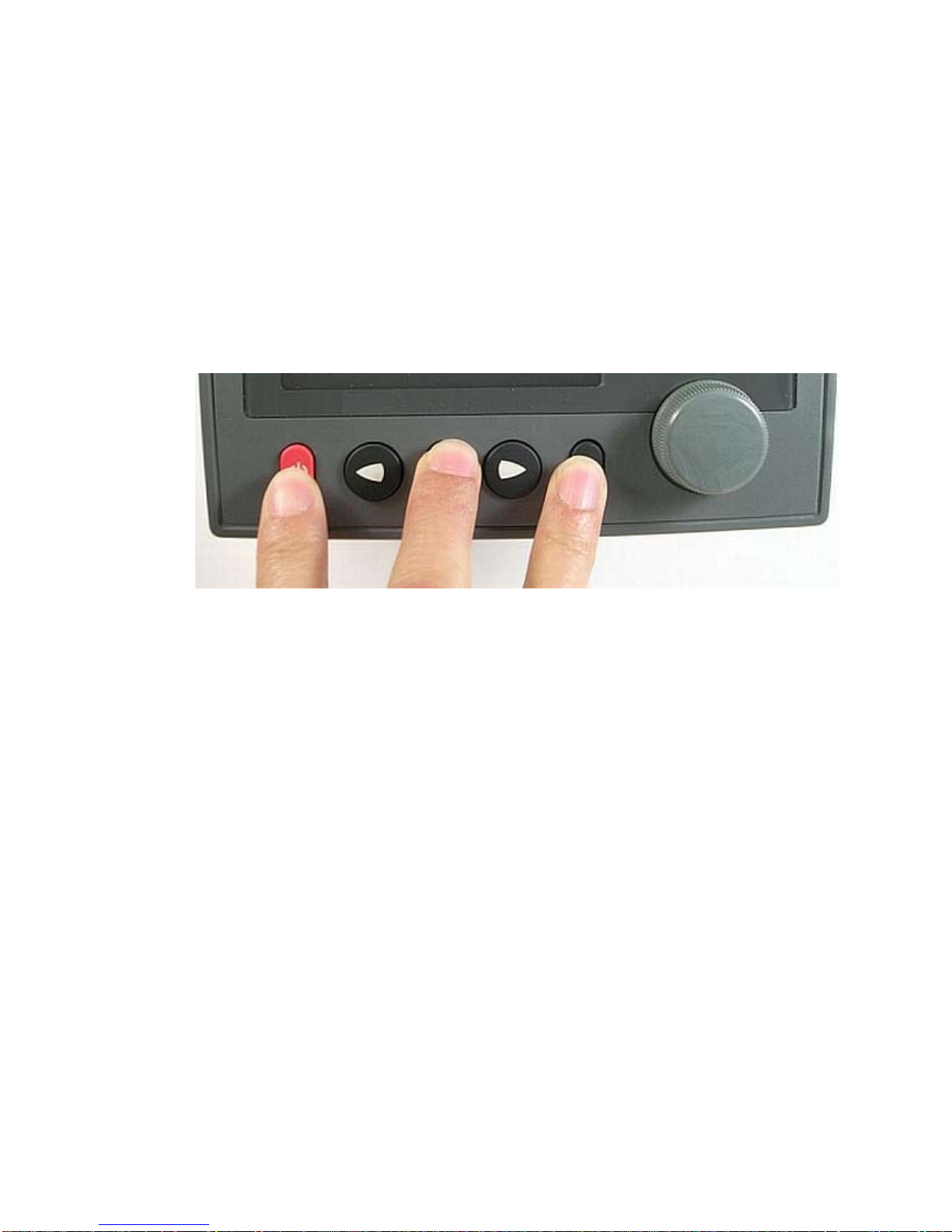
ComNav Commander P2 Installation & Operation Getting Started
Dockside Setup Menu
Accessing the Dockside Setup menu is always necessary during the initial setup of the
autopilot. Typically, it is used only infrequently after initial setup.
A special button sequence must be used to access the Dockside Setup menu:
1) Start with the Commander P2 system powered off.
2) Press and hold the
STANDBY/ON/OFF button. Power will turn on.
3) Hold all three buttons activated until the software version numbers are displayed,
then release the buttons.
Figure 63 – Entering Dockside Setup
4) After a second or two, the display will show the Dockside Setup menu. Note that
a large D (which is the indicator that the system is in Dockside Setup) appears in
the upper left portion of the display.
Fn button and the TURN button. Then press & hold the
The Dockside Setup menu is unlike other menus:
• there is no time-out feature associated with it.
• when you exit it, the P2 system performs a full Power-On sequence, which ends up in
STANDBY mode.
Many of the items listed in the Dockside Setup menu are not simple parameters, but instead
are automated scripts (sequences of pre-defined steps) that perform a variety of functions
and system tests. The letters
are scripts. To activate the associated script, press the
Document PN 29010074 V3.1 - 86 -
Fn on the right hand side of the display identify the items that
Fn button.
Page 87
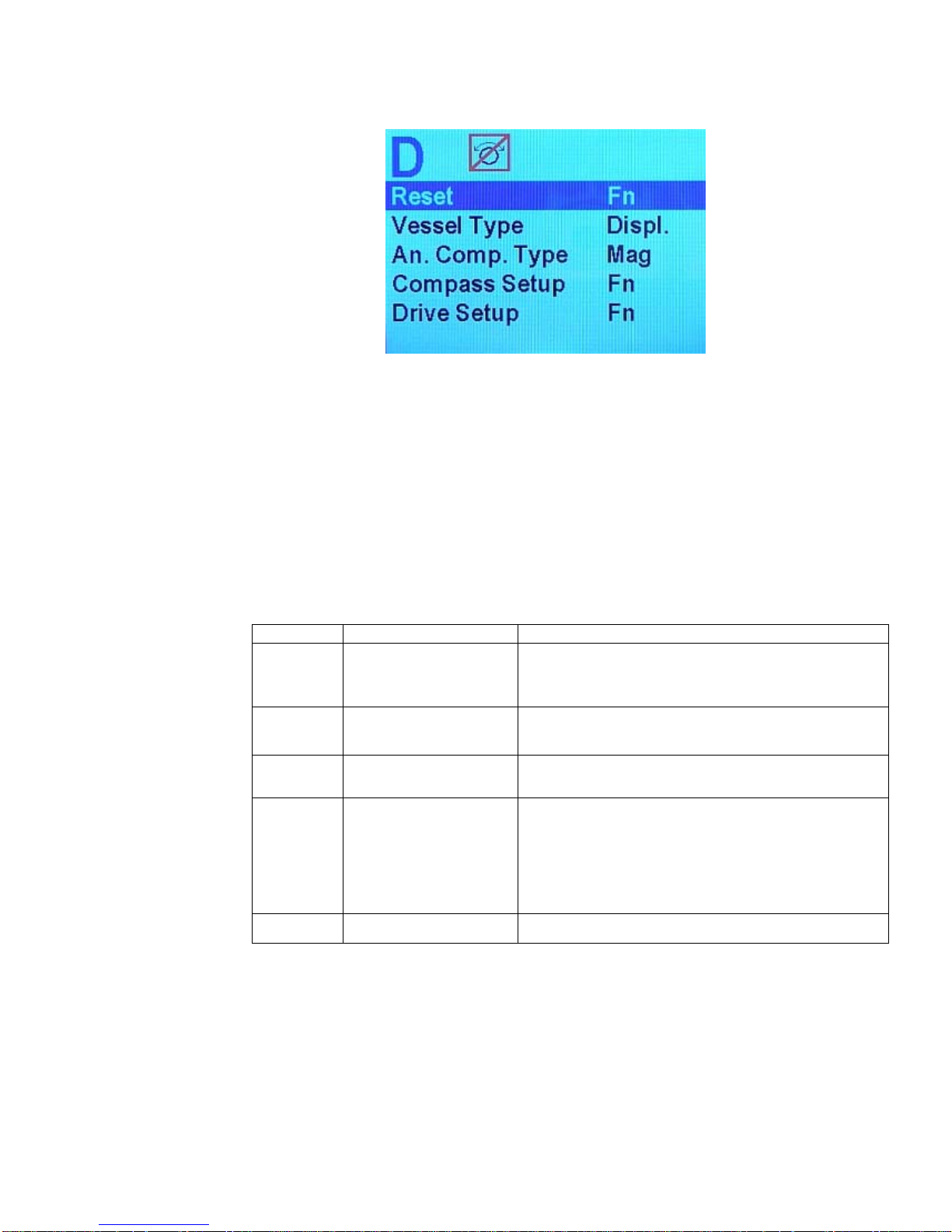
ComNav Commander P2 Installation & Operation Getting Started
Figure 64 – Dockside Setup menu, page 1
Reset
Caution!
Pressing the Fn button when this item is highlighted will reset ALL
parameters in the entire autopilot system back to the factory default settings. This means
any configurations or adjustments you have already made
WILL BE LOST. Use this feature
only on the advice of an authorized ComNav service representative.
Vessel Type
Set this to most closely match the type of vessel that the autopilot is installed on. The system
then automatically uses a set of steering parameters that have been found to work
reasonably well with typical vessels of the chosen type.
Setting Vessel Type Comments
Choose this setting for full displacement vessels
Displ Full Displacement
Semi Semi-Displacement
Plane Planing Hulls
Stern Stern-drive
that do not plane or rise out of the water at cruising
speed.
Choose this if your vessel rises partially out of the
water at cruising speed.
Choose this for vessels that are mostly out of the
water at cruising speed.
Choose this for planing-hull vessels with outboards
or stern-drive legs. If you are using a reversing
motor pump, the pump will operate at a slower
speed when the autopilot is using the Hi steering
parameters. This will result in smoother steering
and rudder movements.
Sail Sailboats For sailing vessels of all types.
Table 3 – Vessel Types
Document PN 29010074 V3.1 - 87 -
Page 88
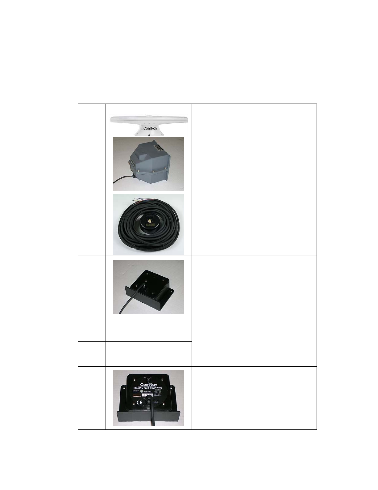
ComNav Commander P2 Installation & Operation Getting Started
An. Comp. Type (Analog Compass Type)
The Commander P2 can work with a variety of different compasses. Many of these are
Analog Compasses that output DC sine and cosine signals. The An. Comp. Type parameter
tells the Commander P2 what specific type of analog compass is connected to the SPU (or if
none is). Analog compasses are always connected to J8 on the SPU. Refer to the following
table for help in identifying and selecting the correct type for the compass in your system.
Setting Compass Type Comments
Choose this setting if your Commander P2
system is utilizing a ComNav 45° Compass
None
Transducer, or any type of NMEA 0183
Compass (such as the ComNav Vector G2
or G2B GPS Compasses).
Mag
Flux
Fixed
Float
HRS
----------
----------
Choose this setting if you have an
externally gimballed magnetic compass
fitted with a ComNav Magnetic Sensor,
such as the one shown to the left.
Choose this if you have a ComNav
Fluxgate Compass like the one shown to
the left.
If you have a ComNav Heading Rate
Stabilizer connected in series with the
Fluxgate Compass, you must use the HRS
setting (below).
The Commander P2 can accept a variety
of Analog compasses. Consult the
manufacturer’s documentation, or contact
the manufacturer, to determine whether
the reference signal is fixed or floating, and
set the An. Compass Type to match.
Choose this setting if you are using a
ComNav Heading Rate Stabilizer like the
one shown at the left.
Table 4 – Analog Compass Types
Document PN 29010074 V3.1 - 88 -
Page 89
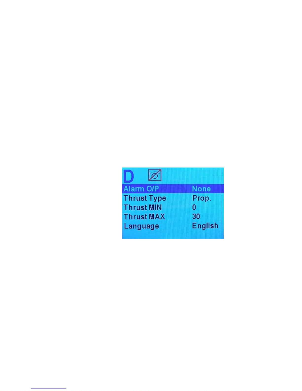
ComNav Commander P2 Installation & Operation Getting Started
Compass Setup
Pressing the Fn button when this item is highlighted tells the Commander P2 to verify the
Analog Compass connections. If the connections are found to be correct, the autopilot will
then query whether you want it to do an automatic compensation of the compass for
Magnetic Deviation. See the Setup Procedures on page 92, and the Compass
Compensation procedures on page 100 for full details.
Drive Setup
Pressing the Fn button when this item is highlighted starts a script in which the Commander
P2 automatically determines the orientation of the rudder follower, measures the physical
rudder limits, figures out what kind of steering system (i.e. reversing motor, solenoid, etc) is
installed, and then tests all these to make sure everything is operating properly. This is
explained more fully under Setup Procedures on page 92.
Exit
Press the Fn button to exit the Dockside Setup menu and restart the autopilot in STANDBY
mode. Alternately, you can press and hold the red STANDBY/ON/OFF button to shut off the
autopilot.
Figure 65 – Dockside Setup menu, page 2
Alarm O/P (Alarm Output)
This parameter controls the functioning of the External Alarm Output. The value shown
indicates which output will be used to activate the external alarm.
When set to “None”, the external Alarm Output is deactivated.
When Set to “SW’D B-“, the Switched B- output (J2-pin 4) will be used to activate the External
Alarm, which should be wired as per Figure 53 or Figure 55 in the Installation chapter.
When Set to “SW’D B+“, the Switched B+ output (J2-pin 3) will be used to activate the
External Alarm, which should be wired as per Figure 54 or Figure 56 in the Installation
chapter.
Document PN 29010074 V3.1 - 89 -
Page 90
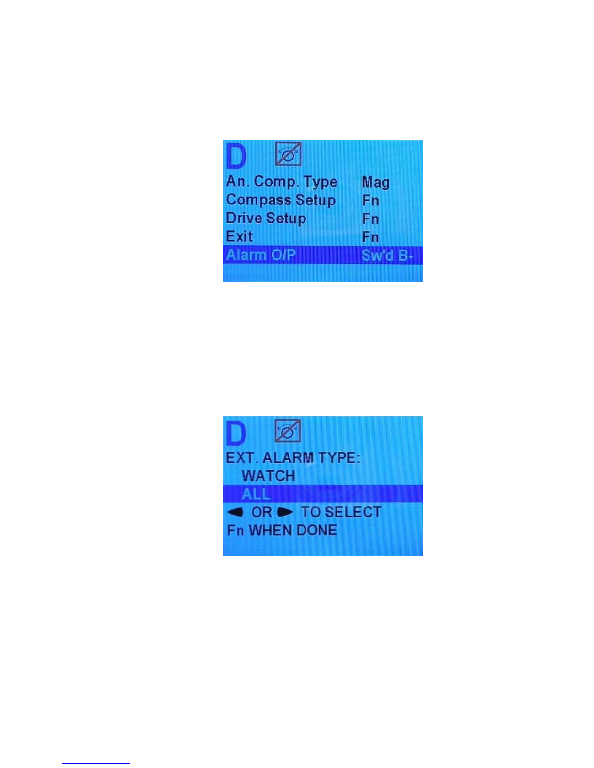
ComNav Commander P2 Installation & Operation Getting Started
To configure the External Alarm Output, follow these steps:
1) Highlight “Alarm O/P” on the screen.
2) Use the COURSE CHANGE knob to select the Alarm O/P that you want to use.
Figure 66 – External Alarm Configuration
3) Press the
Fn button. A new screen will appear. This is where you choose
whether you want to activate the External Alarm Output for all alarms and error
messages, or just when the Watch Alarm has not been answered. Note: The
autopilot will not allow you to change the Alarm O/P without choosing either “All”
or “Watch”. If necessary, it will bring up the option screen before it allows you to
move the highlight off of “Alarm O/P”.
Figure 67 – External Alarm Type Configuration
4) Press the
Fn button to get back to the Dockside Setup menu. You can now
move the highlight to a different parameter.
Document PN 29010074 V3.1 - 90 -
Page 91

ComNav Commander P2 Installation & Operation Getting Started
Thrust Type
Thrust MIN
Thrust MAX
If the optional CT7 Thruster Interface is installed with your Commander P2 system, you will
need to make adjustments to these settings. Complete instructions are included with the CT7
Thruster Interface.
Language
This parameter allows you to set the language used for almost all menus & messages that
appear on the Control Head.
Note that a few items remain in English at all times, typically where there is no simple
translation for that item. Also, the word “Language” on the menu is always shown in English.
Choices are as follows:
• English
• Français
• Español
• Íslenska
• Italiano
Note: other languages may be added in future Firmware Upgrades (see
Appendix 5 on page 177).
Document PN 29010074 V3.1 - 91 -
Page 92
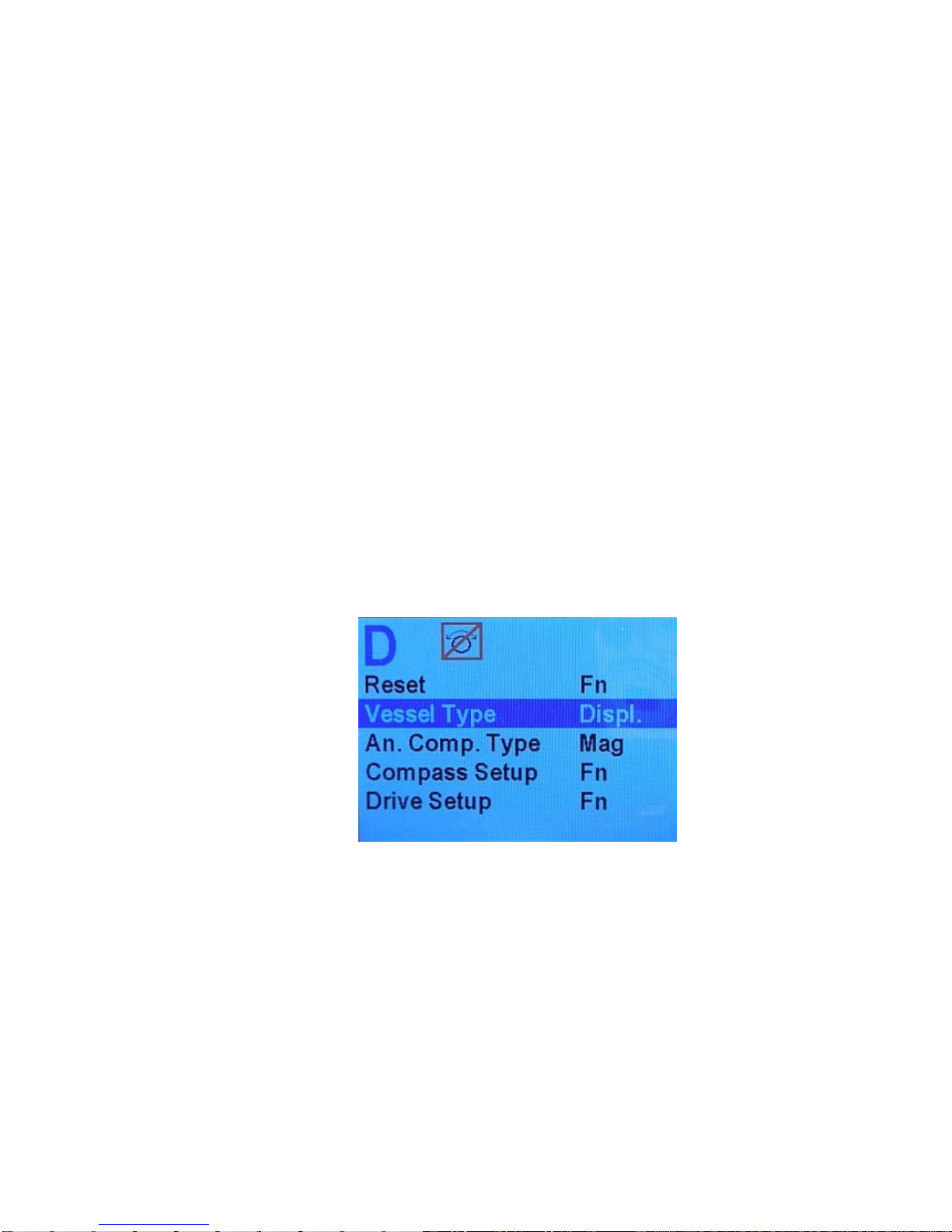
ComNav Commander P2 Installation & Operation Getting Started
Setup Procedures
Once your Commander P2 autopilot system is installed, you must set it up, before you can
use it.
• First, you must tell the P2 what type of vessel you have, and then have the P2 determine
the characteristics of the Rudder Drive mechanism on the vessel.
• Then, you must tell the P2 what type of Compasses it will be using, and have it verify that
it can use those compass(es). Then you must compensate & calibrate all your
compasses.
Vessel Type
1) Access the Dockside Setup menu
• First, ensure that the Commander P2 system s turned off.
• Press and hold the Fn button and the TURN button. Then turn the power on by
pressing the STANDBY/ON/OFF button.
• Hold all three buttons activated until the software version numbers (see page 81) are
displayed, then release them.
• After a second or two, the display will show a large “D” in the upper left portion of the
display, and the Dockside Setup menu will be shown on the screen.
2) Set the Vessel Type according to the chart given in the Vessel Type table (page 87).
Figure 68 – Set Vessel Type
Document PN 29010074 V3.1 - 92 -
Page 93
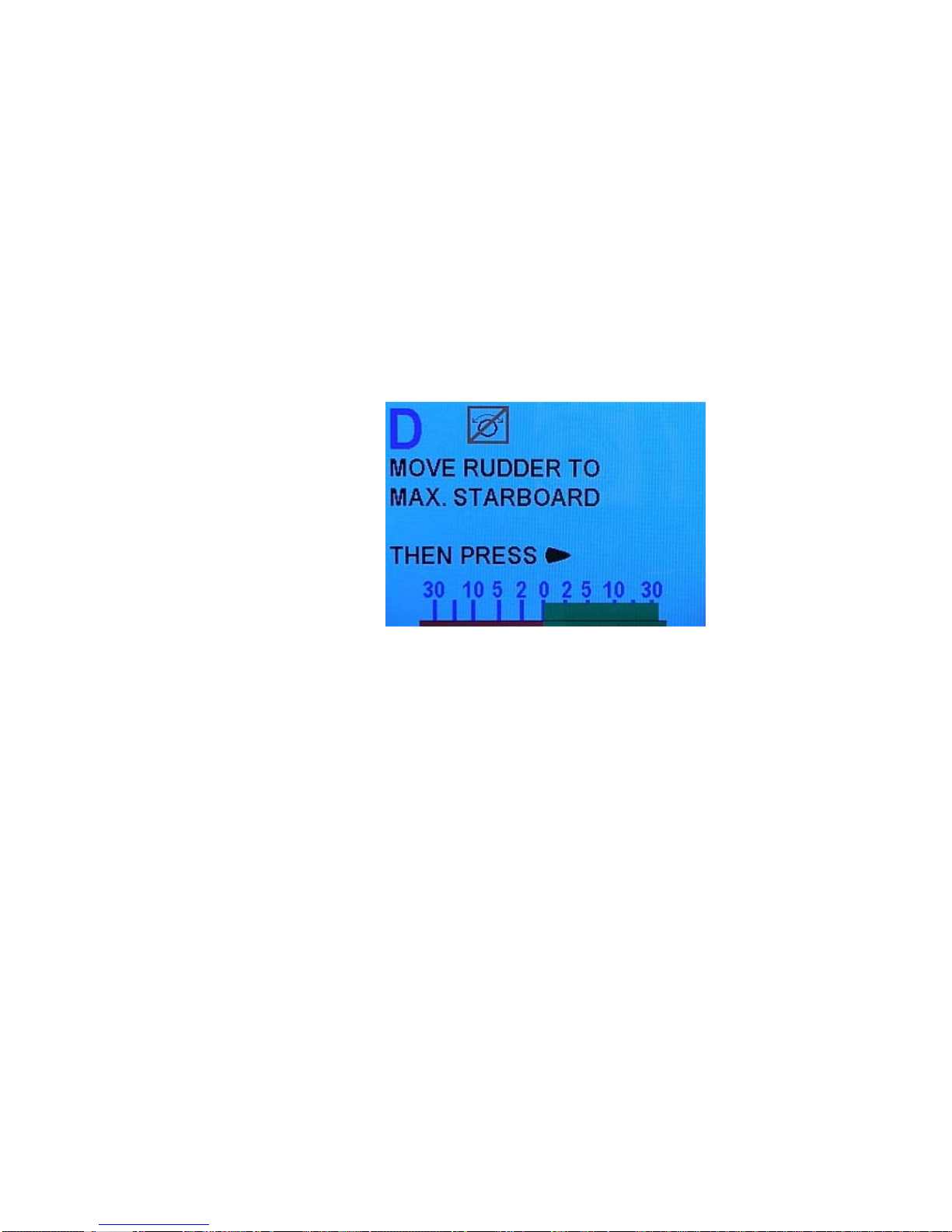
ComNav Commander P2 Installation & Operation Getting Started
Drive Setup
3) Begin the Drive Setup function
In the first part of this automated script, the Commander P2 determines the orientation of
the rudder follower, and where the physical limits of the rudder travel are.
• If you are not still in the Dockside Setup menu, enter it.
• Move the menu highlight to “Drive Setup”, and then press the Fn button, to start
automated script.
• Begin by manually moving the rudder all the way to starboard when prompted. Do
not be concerned if the rudder angle indicator shown on the display appears to go in
the opposite direction. The Commander P2 will sort that out shortly.
Figure 69 – Move Rudder to Starboard
Be sure to move the rudder all the way to the physical stops.
The speed at which you move the rudder does not matter, nor does it matter if you
move the rudder back and forth a bit when it reaches the physical stops, so as to be
sure it has reached those stops.
The autopilot will record the “all the way” position – as measured by the Rudder
Follower – and will ensure, in normal operation, that the rudder is always stopped a
couple of degrees shy of this position, to avoid pounding against the stops.
4) Once the rudder is hard-over, press the STARBOARD ARROW button.
Next, the Commander P2 will prompt you to move the rudder all the way over to the port
side.
• Do so – again, all the way to the physical stops, at any speed you like – then press
the PORT ARROW button.
Document PN 29010074 V3.1 - 93 -
Page 94
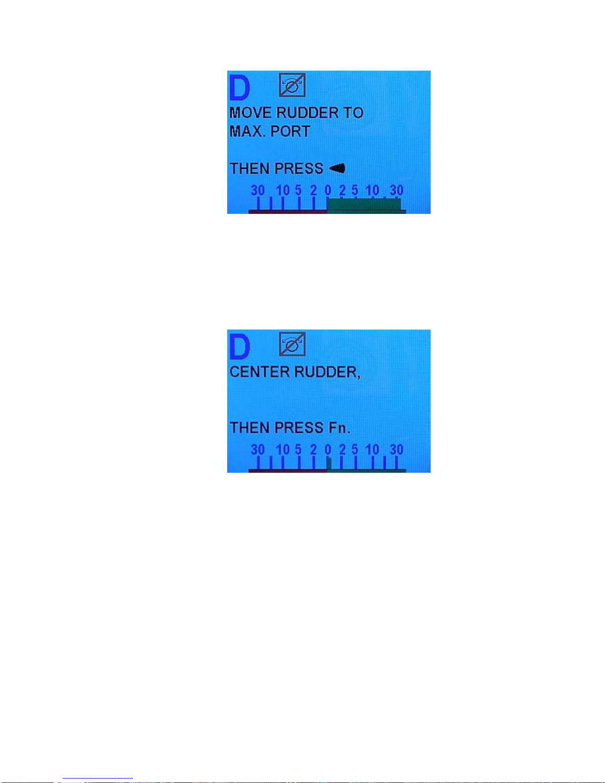
ComNav Commander P2 Installation & Operation Getting Started
Figure 70 – Move Rudder to Port
The Commander P2 will quickly measure the rudder position again, and then prompt
you to move the rudder to the centre position.
• Do so - again, the speed at which you move the rudder does not matter, nor does
some back & forth movement at the centre position. Be sure the rudder is at the
centre position, this time.
Figure 71 – Center the Rudder
Note: these tests also tell Commander P2 how you have wired the Rudder
Follower input, so that the rudder angle indicator on the screen will display
correctly port-wise & starboard-wise movements & positions of the Rudder.
5) Now press the
Fn button on the Control Head, to go to the next phase of the Drive Setup
process.
Document PN 29010074 V3.1 - 94 -
Page 95
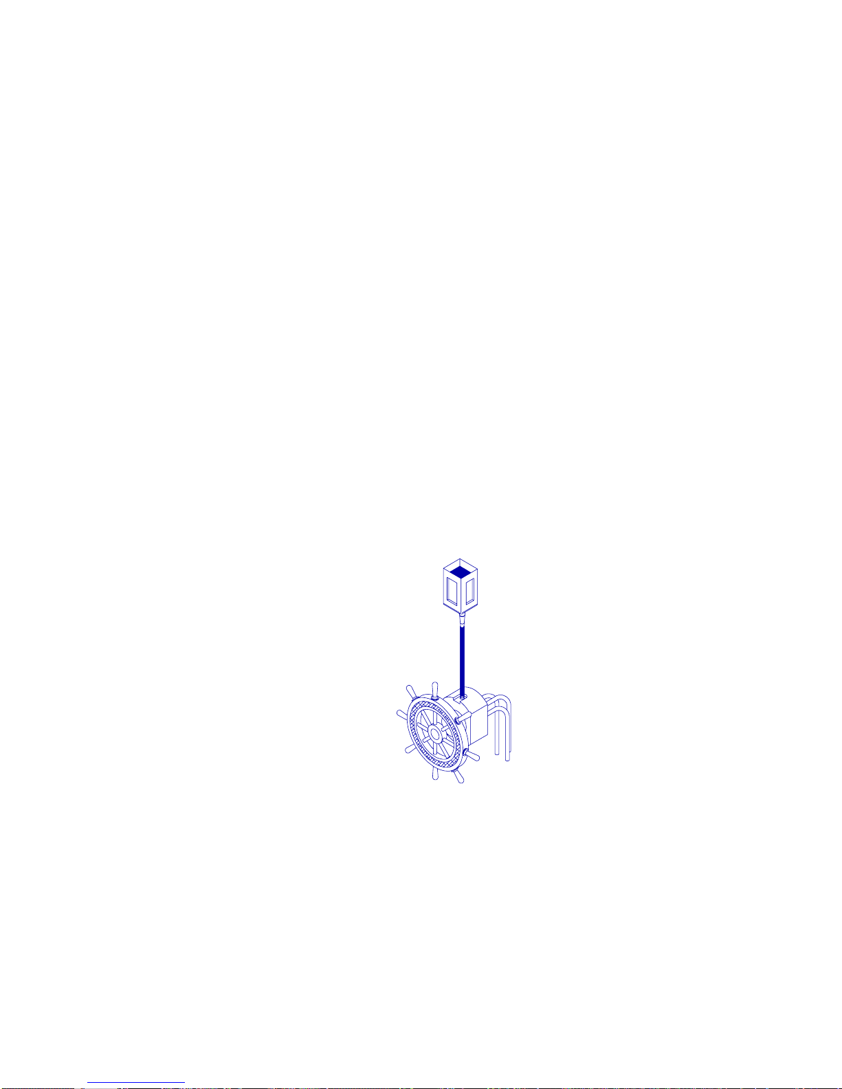
ComNav Commander P2 Installation & Operation Getting Started
Bleeding a Hydraulic Steering System
The Commander P2 will pause the Drive Setup process at this point, and prompt you to bleed
your hydraulic steering system.
Note: If you do not have a hydraulic system, just press the
Fn button on
the Control Head, to carry on with the Drive Setup, and go to step 6) on
page 97.
Whether you have installed an entirely new hydraulic system, or added a hydraulic pump
controlled by the Commander P2 onto an existing mechanical or hydraulic system, the
ENTIRE hydraulic system must be bled of any air trapped in the hydraulic oil, otherwise the
steering system will not perform properly.
Bleeding a typical system using a P2-controlled Reversing Motor hydraulic pump added onto
an existing manual steering system is done in the following steps; other systems will be
similar.
Caution! SAFETY GLASSES SHOULD BE WORN DURING THE STEPS BELOW.
1. First, bleed the manual portion of the steering system (Helm pump, lines & steering
cylinder), according to the manufacturer's instructions. When you have completed
bleeding the manual system, leave the equipment that you used (funnels, catch cans,
etc.) attached to the hydraulic system.
2. Check that the highest hydraulic reservoir in the system is completely filled; top it up,
if necessary. If possible, use a bottle of your system’s hydraulic oil & a piece of
plastic tubing to add extra capacity to the highest reservoir (see the figure below). If
you have a helper, have them watch the oil level in the highest reservoir, and refill it
when necessary.
3. Turn the steering wheel hard against the stop, to press as much oil as possible into
the system. The hydraulic cylinder rod should now be fully extended in one direction.
4. To bleed the Reversing Pump, you will need to extend – using the autopilot – the
cylinder rod in the other direction, and back again, repeatedly, until all air is removed.
Open one bleed screw (or nipple) on the hydraulic cylinder and close the other.
Normally, you close the bleed screw closest to the end of the rod that is now
retracted, and open the bleed screw closest to the rod end now extended (see
Figure 73). Be sure to position the catch can under the open bleed screw, first.
Document PN 29010074 V3.1 - 95 -
Figure 72 – Adding Fluid Capacity
Page 96
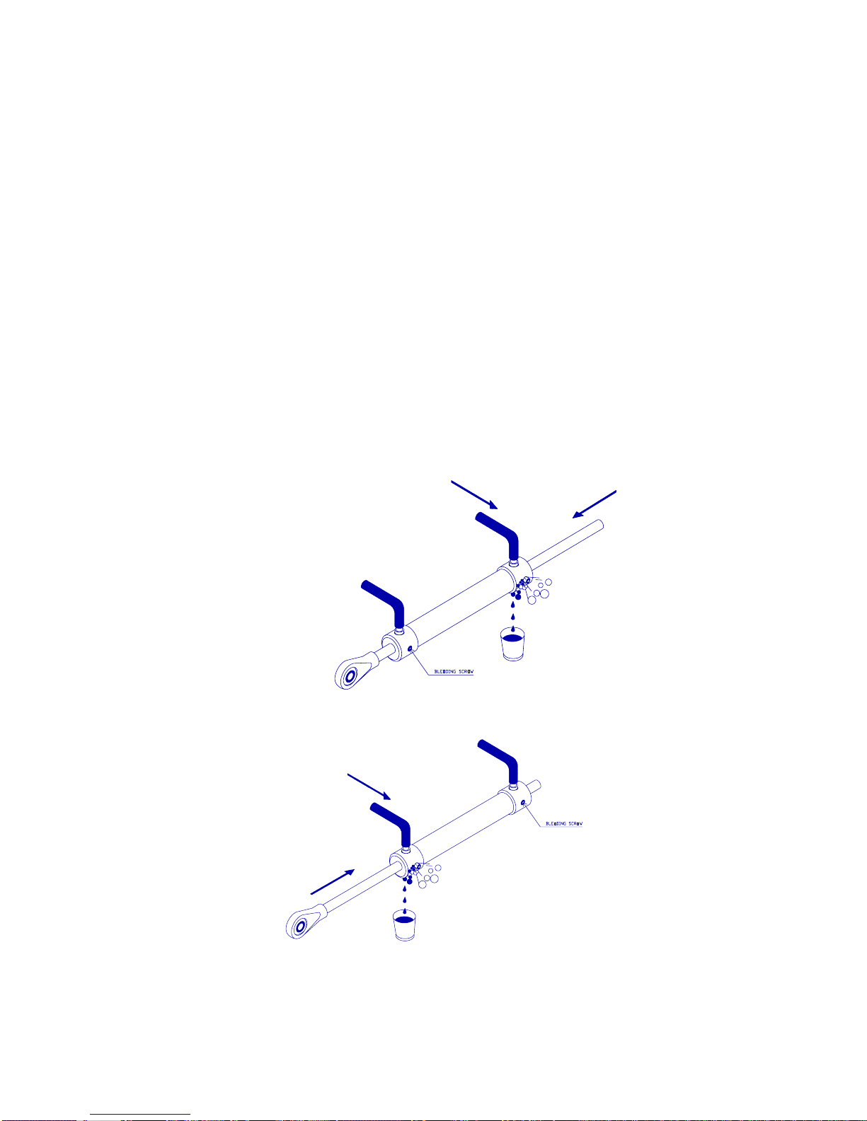
ComNav Commander P2 Installation & Operation Getting Started
5. Position yourself so that you can see the hydraulic cylinder while operating the
Commander P2 Control Head. You can move the steering cylinder rod with the P2’s
Drive outputs, by pressing either the PORT or STARBOARD ARROW button on the
Control Head.
6. Using Control Head, extend the rod as far as it will travel in the other direction. The
Autopilot should stop driving the cylinder shortly after the rod fully extends.
7. Check the steering system’s highest reservoir; re-fill, if necessary.
8. Close the opened bleed screw, re-position the catch can, and open the other screw,
so that the cylinder will be bled when the rod is extended in the original direction.
9. Use the Control Head to fully extend the cylinder rod to the other side.
10. Check/re-fill the highest reservoir.
11. Repeat steps 6 through 10 at least ten times, until all air has been removed from the
cylinder and lines – that is, no air bubbles appear along with the oil coming out of the
opened bleed screw, or trapped in the oil.
12. Close all bleed screws. Clean up any spills of oil and wipe fittings clean. Move your
funnels, catch cans, etc. away from the steering system.
13. Use the Control Head to extend the rod fully in one direction and then the other.
14. Check for leaks by looking for spilled hydraulic fluid near, or on, fittings and cylinders.
Figure 73 – Bleeding Cylinder, Rod moving left
Figure 74 – Bleeding Cylinder, Rod moving right
When all Bleeding is done, press the Fn button on the Control Head, to carry on with the
Drive Setup.
Document PN 29010074 V3.1 - 96 -
Page 97
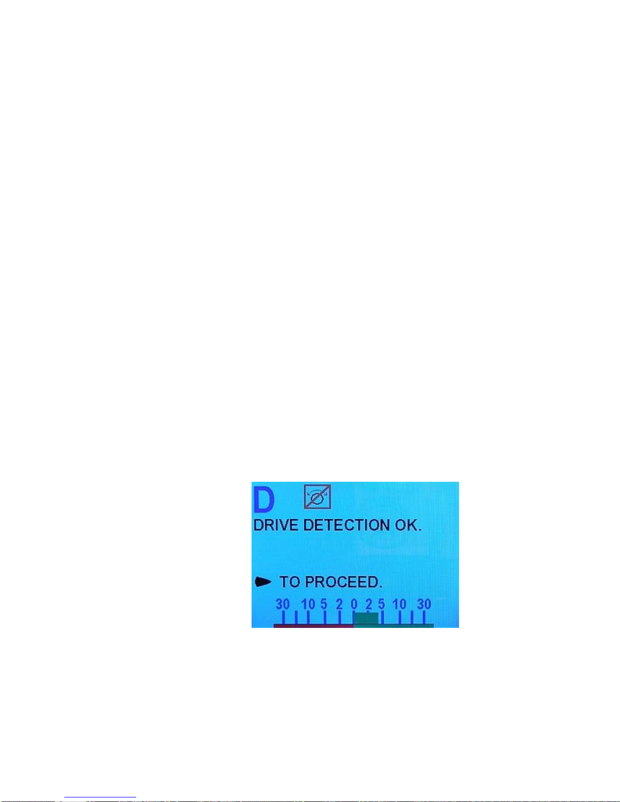
ComNav Commander P2 Installation & Operation Getting Started
Drive Setup (continued)
6) When you press the Fn button (when the “Bleed?” screen was displayed, after bleeding
the hydraulic system, or if you skipped that step), the Commander P2 will fully test the
drive system. This involves the autopilot automatically running the rudder from hard-over
to hard-over a number of times, and possibly making some speed adjustments to the
reversing motor pump-set (if one is installed on your system). The autopilot will also
make a series of short starts and stops of the rudder (pump, motor, etc.) in order to
determine a base reference for how the steering system responds.
Note: if your steering system is very slow – with a Hard-Over to Hard-Over
time greater than about 22 seconds – the Drive Setup procedure will give you
a warning message, but it will still be completed. You may wish to consider
upgrading your steering system in this case, so that the
heading/course/track-keeping performance of the autopilot is not degraded
by the slowness of the steering system.
If the HO-HO time is greater than ~32 seconds, the Drive Setup procedure
will fail. In this case, you will definitely have to improve your steering
systems’ performance.
When the HO-HO time is too slow, it is usually an indication (on hydraulic
systems) that the hydraulic pump is too small, the cylinder is too large, or that
there may be a faulty valve in the system.
On the other hand, if your steering system is extremely quick – with an HOHO time of less than ~5 seconds – the autopilot will deliberately slow it down,
by using Pulse Width Modulation of the Drive output voltages, during
autopilot-controlled Rudder movement. PWM in effect lowers the voltage
“seen” by your Rudder Drive motor(s), and thus slows down the resulting
Rudder HO-HO time.
When the HO-HO time is too fast, it is usually an indication that the hydraulic
pump is oversized.
7) Once the Commander P2 has finished measuring the drive, it will display the following
message:
Figure 75 – Drive Test OK
8) Press the STARBOARD ARROW button to return to the Dockside Setup menu.
9) Exit the Dockside Setup menu.
Document PN 29010074 V3.1 - 97 -
Page 98
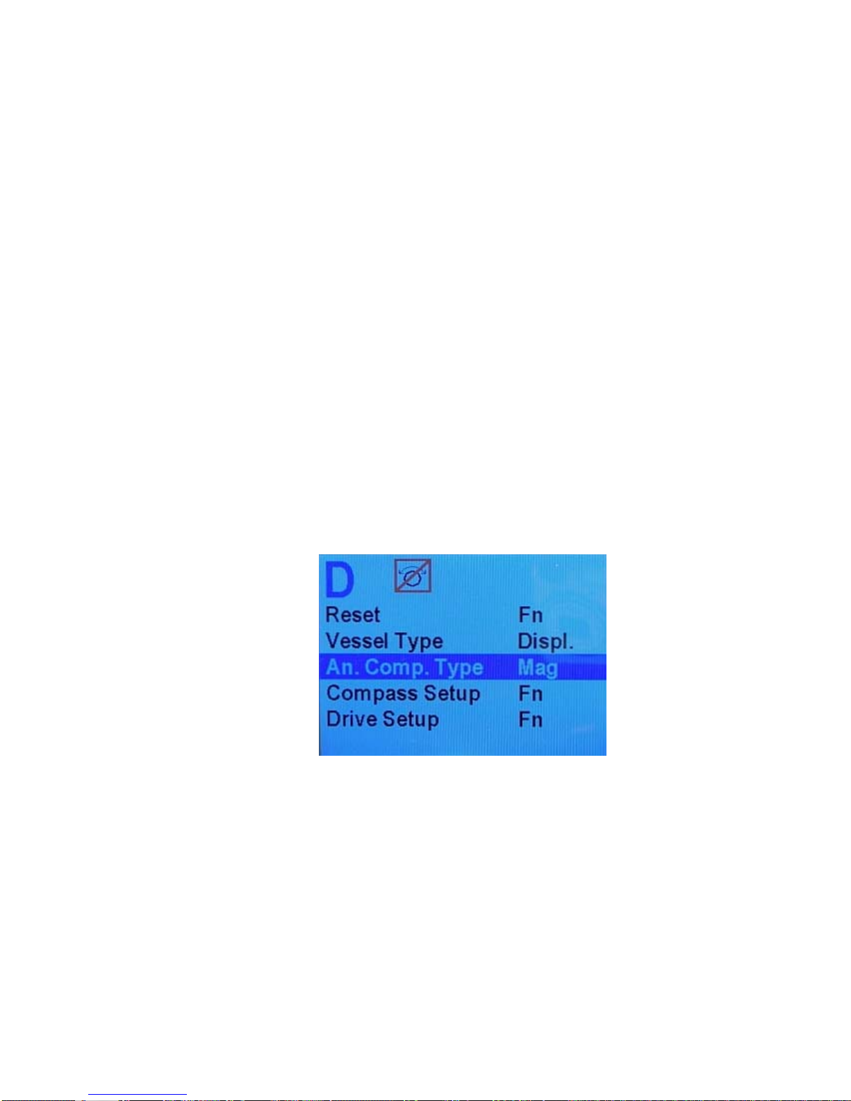
ComNav Commander P2 Installation & Operation Getting Started
Compass Setup – Dockside
The first steps in setting up your compasses are to select which type (or types) you have, and
to verify that they are properly wired to the SPU.
These steps should be done while tied up to the dock, in case any re-wiring needs to be
done, or if it turns out that some elements of the P2 system need to be moved.
Note: if you are using only an NMEA compass (such as a Vector G2 GPS
Compass), you should select “None” in step 1), and then skip the rest of these
steps (both the at-the-dock steps here, and the on-the-water steps in the next
section) entirely.
Instead, you should follow the Compass Setup instructions that were supplied
with the NMEA compass.
Note: during these steps, the autopilot may issue an INVALID HEADING alarm
(see page 170). These alarms can be ignored, or cancelled by hitting the
button.
Once a compass is found in this procedure, the alarms should cease.
1) If you are not already in the Dockside Setup menu, enter it.
Fn
• Select the compass type(s):
Move the highlight to “An. Compass Type”, and set the type according to your system
configuration (see Table 4 on page 88).
Figure 76 – Set Compass Type
2) Verify that the selected compass type is properly connected, and can be read.
Select “Compass Setup” on the menu, then press
displayed on the screen for a few seconds, and then the results of the “search” will be
displayed, along with an option to “compensate now …” or “set North now …” (the type of
compass shown & the “compensate” option will depend on what you entered for “An.
Comp. Type”).
Fn. A “Wait …” screen will be
Document PN 29010074 V3.1 - 98 -
Page 99
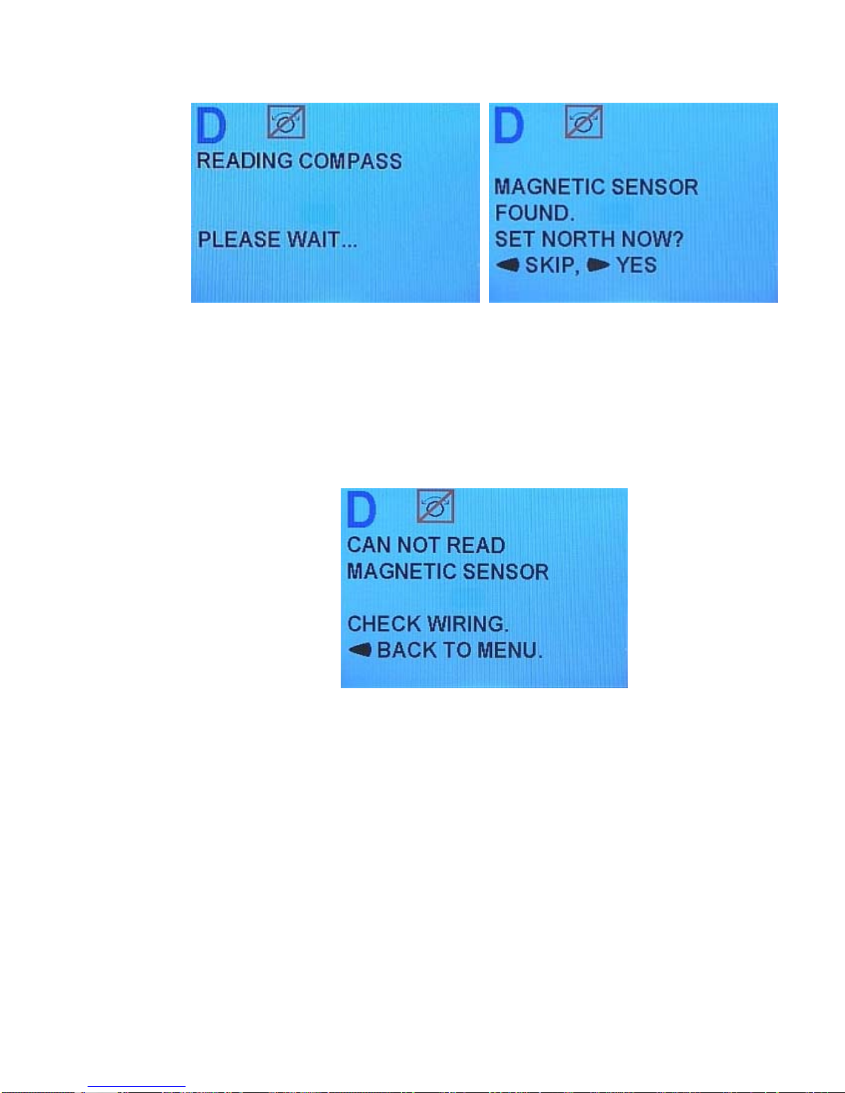
ComNav Commander P2 Installation & Operation Getting Started
Figure 77 – Compass Verification (Mag Sensor shown)
• If the Commander P2 system could not find a compass that matches with the type
you have selected in step 1), it will give the following error message at this point (the
type of compass shown will depend on what you entered for “An. Comp. Type”):
Check your installation to be sure that the compass is wired correctly. Fix any
problems, and re-start at step 1).
Figure 78 – Compass Verification Failed
⇒ If the Commander P2 system still cannot find any installed analog compasses,
contact your ComNav Dealer for help.
3) Press the PORT ARROW button, to skip the compass compensation & calibration
process (this can not be done while still tied up at the dock).
4) If you have installed more than one type of Analog Compass, and/or a 45° Compass
Transducer, repeat steps 1) through 3) for all such compasses.
5) Exit the Dockside Setup menu.
Document PN 29010074 V3.1 - 99 -
Page 100

ComNav Commander P2 Installation & Operation Getting Started
Compass Setup – On the Water
The final part of compass setup is normally performed after all other installation and setup
procedures for the Commander P2 system are completed, so that all net electrical and
magnetic effects of the installation on the compass(es) are taken into account.
Note: some of the steps performed here require that you be familiar with
the STANDBY mode & menu of the Commander P2 system (see page
111).
This part of compass setup requires taking your vessel away from the dock, and out onto a
body of open water (the sea, a lake, a river, etc.), and should be done in relatively calm
conditions.
It is important that there be sufficient sea room to put the boat through a series of fairly slow
& wide circle turns, and to run the boat for several minutes in a straight line at various
headings, without encountering obstacles, other marine traffic, etc. You should also avoid
areas around bridges, underwater power lines, and pipelines, as these can affect your
compasses.
Caution! Be sure to keep a proper lookout for other vessels, and any hazards,
while doing any of the circle turns & other manoeuvres described below.
Compass Compensation
The specific procedure you will follow depends on the type(s) of compasses you have
installed. Each is described below.
Note: during all these procedures, the INVALID HEADING alarm may
occur. You can cancel any such alarm, or leave it active.
Magnetic Compass Sensor
If you have a magnetic compass with a ComNav Magnetic Sensor attached, the compass
must be properly compensated for deviation. It is recommended that a professional compass
adjuster do this.
Once the compensation is completed, follow the instructions below to synchronize the
Magnetic Sensor with the Earth’s Magnetic North direction:
1) Power up the autopilot. Double-press the STANDBY/ON/OFF button to bring up the
Standby menu. Select “Compass Source”, and make sure it is set to “Analog”.
2) Shut off the autopilot, then power it up in the Dockside Setup menu.
3) Ensure that the “An. Compass Type” is set to “Mag”.
4) Select Compass Setup & press the
5) After the Commander P2 has auto-detected the compass, it will ask you if you want
to SET NORTH NOW? (see Figure 77). Press the STARBOARD ARROW button.
Manually steer the vessel so that it is pointing to Magnetic North. Hold it on that
heading and push the
and reference it as 000° Magnetic. When this is done, the Commander P2 will
automatically return to the Dockside Setup menu.
Fn button. The Commander P2 will store the current heading
Fn button.
6) Highlight “Exit” and then press the
restart and automatically go into STANDBY mode.
7) Now do the Compass Calibration procedure, on page 104.
Document PN 29010074 V3.1 - 100 -
Fn button. After a brief pause the autopilot will
 Loading...