

Page 1
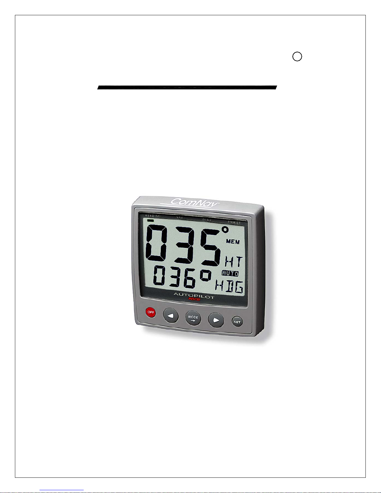
R
ComNav
Marine Ltd.
1500 Autopilot – Stand Alone System
1510 Autopilot – Network System
Operation & Installation Instructions
Version 2.0
Page 2

ComNav 1500 / 1510 Autopilot
W
elcome
Congratulations on your purchase of ComNav Marine’s NX2 1500 Autopilot System! At ComNav, we
are proud of our prominence as a leader in the design and manufacture of marine Autopilot systems.
Our dedication to performance and reliability will ensure your satisfaction with the ComNav 1500.
Developed as a result of ComNav’s many years of experience in Autopilot design, the 1500 system
provides excellent performance and more features than any other Autopilot in its class.
Yours truly,
Page 3

ComNav 1500 / 1510 Autopilot
Warranty Notice
Prior to the installation and/or operation of the
equipment, ensure that you read, understand and
accept the conditions of the warranties as
detailed in Section 12 of this manual.
Operator’s Warning
The Autopilot will automatically steer your vessel,
however it is only an aid to navigation. Its
performance can be affected by many factors
including equipment failure, environmental
conditions and improper handling or use. This
system does not reduce your responsibility for
the control of the vessel when underway. You
must always be in a position to monitor the
course, supervise the Autopilot, and resume
manual control if the need to do so arises.
Whenever underway, your vessel must be under
the control of a qualified and alert person.
Page 4

ComNav 1500 / 1510 Autopilot
About This Manual
This manual provides essential information for the safe and
reliable operation of the 1501 Autopilot System. You are urged to
read this manual in its entirely before you use your Autopilot for
the first time, and to keep it handy until you become thoroughly
familiar with the operation of your Autopilot.
Throughout this manual, you will see a number of different
typefaces used, as well as some distinct phases, or “jargon”.
Please take a moment to become familiar with the following terms:
• Each time a push-button is referred to in this manual, the push-button name will
appear in bold and CAPITAL letters, e.g. MODE.
• Unless otherwise stated, the push-button presses are momentary.
• Each time a function is mentioned in the text, it will be in brackets and in the
same format, where possible, as displayed, e.g. [HDG] for HeaDinG.
• With the word navigator we mean a GPS, Loran or Decca instrument.
• Which instrument is navigating? By the term navigating, we mean the active
instrument in which the waypoint memory is used for navigation to calculate the
navigation data, i.e. BTW, DTW etc. There can only be one instrument on the
NX2 Network which is keeping the waypoints in memory, but the waypoints can
be reached from all instruments.
Page 5

ComNav 1500 / 1510 Autopilot
1. INTRODUCING THE COMNAV NX2 1500 AUTOPILOT .......................................... 1
1.1 Capabilities............................................................................................................. 1
1.2 Principle of Operation............................................................................................. 2
1.3 Components........................................................................................................... 3
1.3.1 Autopilot Instrument Control Head...................................................................... 3
1.3.2 45 ° Flux Gate Compass..................................................................................... 3
1.3.3 35 ° Flux Gate Compass..................................................................................... 3
1.3.4 Distribution Unit ..................................................................................................3
1.3.5 Rudder Follower & Linkage ...............................................................................3
1.3.6 Reversing Pumpsets........................................................................................... 4
1.3.7 Linear Drive ........................................................................................................4
1.3.8 Solenoid Valve Drive ..........................................................................................4
1.4 Accessories............................................................................................................ 5
1.4.1 NX2 Autopilot Instrument Control Head.............................................................. 5
1.4.2 NX2 Remote Control Instrument......................................................................... 5
1.4.3 NX2 Analog Rudder Angle Indicator Instrument (RAI) .......................................5
1.4.4 NX2 Multi Control Instrument with Server........................................................... 5
1.4.5 External Alarm Buzzer ........................................................................................ 5
1.4.6 NFU Jog Lever.................................................................................................... 5
2. INSTALLATION .........................................................................................................6
2.1 General Comments ................................................................................................ 6
2.2 Distribution Unit 1500 & 1510................................................................................. 7
2.2.1 Distribution Unit Connections ...........................................................................10
2.2.2 Safety Switch .................................................................................................... 10
2.2.3 DIP Switches ....................................................................................................10
2.2.4 Trim Potentiometers .........................................................................................10
2.3 Control Head ........................................................................................................ 11
2.4 Flux Gate Compass.............................................................................................. 13
2.5 Rudder Follower & Linkage ................................................................................. 15
2.6 Analog Display Rudder Angle Indicator................................................................ 16
2.7 NMEA 0183 Compass Interface...........................................................................17
2.8 LFU101 Full Follow Up (FFU) Tiller Steering ....................................................... 17
2.9 Reversing Pumpsets ............................................................................................ 17
2.10 Installing Fittings................................................................................................ 20
2.11 Mounting the Pumpset......................................................................................20
2.12 Piping the System.............................................................................................21
2.13 Filling the System .............................................................................................21
2.14 Linear Drive ......................................................................................................21
2.15 Solenoid Valve Controlled Pumpsets ...............................................................23
2.16 Accessories ......................................................................................................23
3. ADVANCED OPERATION.......................................................................................24
3.1 Adjusting Response (See Calibration Menus)...................................................... 24
3.2 Rudder [RUD] Function ........................................................................................ 24
3.3 Sea State [SEA] Function..................................................................................... 24
3.4 Counter Rudder [CRD] Function .......................................................................... 24
3.5 Automatic Trim [ATC] Function ............................................................................ 25
4. AUTOPILOT INSTRUMENT CONTROL HEAD OPERATION ................................ 26
4.1 Instrument Overview ............................................................................................26
4.1.1 Instrument Display.............................................................................................26
4.1.2 Instrument Pages and Functions...................................................................... 26
Page 6

ComNav 1500 / 1510 Autopilot
4.1.3 Instrument Modes ............................................................................................. 26
4.1.4 Power On/Off .................................................................................................... 26
4.2 How to Use the Push-Buttons .............................................................................. 27
4.2.1 MODE................................................................................................................27
4.2.2 LEFT.................................................................................................................. 27
4.2.3 RIGHT ...............................................................................................................27
4.2.4 SET.................................................................................................................... 27
4.2.5 OFF ...................................................................................................................27
4.2.6 Tack................................................................................................................... 27
4.2.7 Setup Mode ......................................................................................................28
4.2.8 Lighting ............................................................................................................. 28
5. FUNCTION ..............................................................................................................29
5.1 Standby Mode ......................................................................................................29
5.2 Autopilot Mode .....................................................................................................29
5.2.1 Activate Automatic Steering ............................................................................29
5.2.2 Turn Off Automatic Steering ............................................................................ 29
5.2.3 Automatic Steering by Compass .....................................................................30
5.2.4 Automatic Steering by Navigator ...................................................................... 30
5.2.5 Automatic Steering by Wind ............................................................................. 31
5.2.6 Power Steering................................................................................................. 32
5.2.7 Dodging and Returning to last Automatic Steering Function............................ 32
6. SETUP..................................................................................................................... 33
6.1 Setup Mode.......................................................................................................... 33
6.1.1 Setup Mode Divided into 4 Setup Groups ........................................................33
6.1.2 Access Setup Mode..........................................................................................33
6.1.3 Change a Setting.............................................................................................. 33
6.1.4 Return to Previous Mode .................................................................................. 33
6.1.5 Factory Default Settings ...................................................................................33
6.2 Lighting Setup Group [Lit]..................................................................................... 34
6.3 Autopilot Setup Group [P].....................................................................................34
6.3.1 P0, Return [RET] ..............................................................................................34
6.3.2 P1, Rudder [RUD].............................................................................................34
6.3.3 P2, Damping of compass heading [SEA].......................................................... 35
6.3.4 P3, Counter Rudder [CRD]................................................................................35
6.3.5 P4, Damping of wind [WSE] .............................................................................. 36
6.3.6 P5 Automatic Trim Calibration [ATC]................................................................. 36
6.3.7 P6, Adaptive Control [ADC] ............................................................................... 36
6.3.8 P7, Automatic Pilot Calibration [APC]...............................................................36
6.3.9 P8, Rudder Reduction Speed [RRS] ................................................................37
6.3.10 P9, Rudder angle limit [LIM].......................................................................... 37
6.4 Alarm Setup Group [A] ......................................................................................... 38
6.4.1 A0, Return [RET] ..............................................................................................38
6.4.2 A1, Pilot Course Alarm [PCA]...........................................................................38
6.4.3 A2, Timer Watch Alarm [TMR]..........................................................................38
6.4.4 A3, Cross Track Error Alarm [XTA] ...................................................................38
6.4.5 A4, Push-Button Beep [KEY].............................................................................38
6.5 Compass Setup Group [C] ................................................................................... 39
6.5.1 C0, Return [RET] .............................................................................................. 39
6.5.2 C1, Magnetic Heading [MAG] ........................................................................... 39
6.5.3 C2, Local Magnetic Variation [VAR] .................................................................39
6.5.4 C3, Auto-Deviation [Auto DEV].........................................................................39
Page 7

ComNav 1500 / 1510 Autopilot
6.5.5 C4, Check Auto-Deviation [Auto CHK] .............................................................40
6.5.6 C5, Clear Auto-Deviation [Auto CLR] ................................................................ 40
6.5.7 C6, Adjust Compass Alignment [ADJ] .............................................................. 41
7. DOCKSIDE TESTING.............................................................................................. 42
7.1 Preparations......................................................................................................... 42
7.2 Dockside First Start Up ........................................................................................42
7.2.1 Power On........................................................................................................... 42
7.2.2 Initializing the Instrument in a NX2 Network......................................................42
7.2.3 Re-Initializing the Instrument ............................................................................ 43
7.3 Remove Air from System .....................................................................................43
7.4 Adjust the Pumpset Flow Rate ............................................................................. 44
7.5 Functional Tests................................................................................................... 44
8. SEA TRIALS ............................................................................................................ 45
8.1 Preparations......................................................................................................... 45
8.2 Compass Calibration............................................................................................ 45
8.3 Automatic Pilot Calibration [APC].........................................................................45
9. FINE TUNING.......................................................................................................... 47
9.1 Optional Fine Tuning for Special Applications...................................................... 49
10. PROBLEM SOLVING...........................................................................................50
10.1 General............................................................................................................. 50
10.2 Symptom - Cause - Action................................................................................50
10.3 NX2 Network Error Messages with Cause and Remedy .................................. 53
11. MAINTENANCE ................................................................................................... 55
11.1 Instrument Maintenance ................................................................................... 55
11.2 Drive Unit Maintenance and Inspection Schedule ............................................ 55
12. TECHNICAL SPECIFICATIONS.......................................................................... 56
12.1 Autopilot Instrument.......................................................................................... 56
12.2 Distribution Unit A-1500.................................................................................... 56
12.3 Distribution Unit A-1510.................................................................................... 56
12.4 Rudder Follower & Linkage .............................................................................. 56
12.5 Pumpsets.......................................................................................................... 57
12.6 Linear Drive ...................................................................................................... 57
12.7 Solenoid Valve Drive ........................................................................................ 57
12.8 NX2 Network Specific
ation ............................................................................... 57
13. Abbreviations........................................................................................................ 58
Page 8

ComNav 1500 / 1510 Autopilot - 1 -
1. INTRODUCING THE COMNAV NX2 1500 AUTOPILOT
1.1 Capabilities
The ComNav NX2 1500 and 1510 Autopilots are designed for power and sailing
vessels from 26ft (8m) to over 160ft (50m) length. Design and manufacturing
techniques developed over many years have resulted in a versatile and heavy-duty
unit. Hydraulic drive units of the reversible motor variable speed (PWM) type provide
precise control while consuming low battery power. Connection can be made to
solenoid valves of electro-hydraulic steering systems, allowing use on very large
vessels. Hydraulic linear drives provide powerful and accurate control when
connected to mechanical steering systems and provide an independent hydraulic
steering for added safety.
No Autopilot can steer better than its compass stability will allow and the flux gate
compass excels in this characteristic. Silicone oil dampening of the flux gate
prevents compass instability even for high speed vessels slamming in heavy seas.
This combined with the high gimbal angle of +/- 45°, eliminates compass
disturbance with vessel heeling or rolling. A sensitive automatic gain design
provides improved compass operation especially in high latitudes and automotive
deviation compensation ensures accurate indication. As an alternative an NMEA
0183 output flux gate compass can be connected to this Autopilot for greater
interfacing flexibility. An optional fluid compass sensor may be used and slaved to
the vessel’s main magnetic compass if it is of the externally gimballed type. This is
particularly important on steel-hulled vessels. For larger vessels a gyro-compass
may be interfaced for even greater steering accuracy.
Power steering, either through the Control Head push buttons or an operational jog
steering level may be used to avoid heavy wheel effort when maneuvering.
Alarms for off course, off track or watch alarm and other faults are included with
provision for an optional loud remote alarm. Interface to radio navigational receivers
including GPS, Loran, Satnav, Decca and Plotters allows precise waypoint arrival
and multiple waypoint sequencing. Unique adaptive controls provide very powerful
and smooth steering control which automatically adjusts to changing operational
conditions.
A large number of Autopilot stations may be connected. Control techniques
developed over many years allow very stable course holding with minimum
corrections. Weather helm is automatically compensated for by an automatic trim
and counter rudder that provides enhanced response in quartering seas under large
course changes. Some Autopilot features described above may not be available
with the 1510 system.
Page 9

ComNav 1500 / 1510 Autopilot - 2 -
1.2 Principle of Operation
The powerful microprocessor in the Distribution Unit accepts heading information
from magnetic or gyro compasses and radio navigation receivers and compares this
against the course set by the Control Head and rudder information as sent by the
Rudder Transmitter. Any difference between the set and actual course is compared
along with the rate of change and trends in change (PID control), to drive the
Pumpset motor or solenoid directional valve, moving the rudder as necessary to
return the vessel back to course. The sensitivity to course errors and amount of
correction are user adjustable to suit different vessels under changing sea
conditions. Factory default settings establish a basis for normal steering and may be
further optimized as necessary. During set up procedures, the compass is
automatically compensated and installation errors such as reversed rudder feedback
and reversed Pumpset wiring or piping are automatically diagnosed and corrected.
During this procedure the rudder speed is automatically optimized. This greatly
reduces installation calibration and sea trials time while eliminating possible
Autopilot malfunction.
Page 10
1.3 Components
T
O
L
T
E
S
PI
2
TO
N
U
A
E
D
O
M
F
F
O
ComNav 1500 / 1510 Autopilot - 3 -
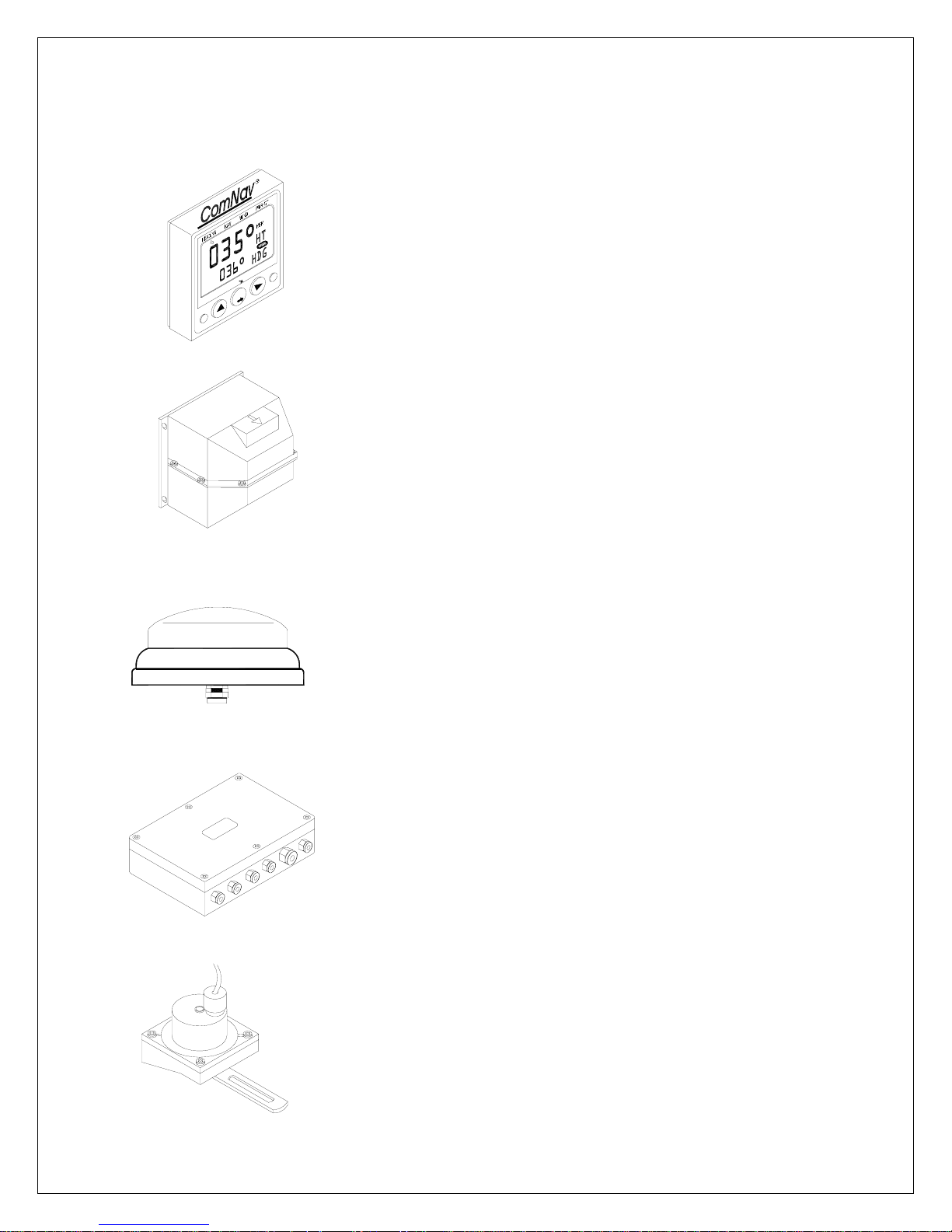
1.3.1 Autopilot Instrument Control Head
The control and display of all Autopilot functions are provided
by the Control Head. It is waterproof and may be mounted
below or above deck. Multiple Control Heads are connected
in parallel (daisy chain) and any station may be activated by
pressing any one of its keys. A portable Control Head is also
available for remote control (not shown).
PN 20620044
1.3.2 45 ° Flux Gate Compass
The flux gate compass provides a stable heading reference
for the Autopilot and course repeater function on the Control
Head. It is gimbaled to accept up to +/- 45 ° of pitch and roll
and should be bulkhead mounted below decks near the
center of pitch and roll for maximum stability. Construction is
splashproof. The Autopilot may also be used to transmit
NMEA heading data to additional receivers such as radars,
plotters, compass repeaters etc.
PN 20640006
1.3.3 35 ° Flux Gate Compass
The flux gate compass is low weight, fluid damped and
compact in size allowing for mounting in cramped areas. It
can be flush mounted and is auto-deviated from the Autopilot
Instrument Control Head.
PN 20640007
1.3.4 Distribution Unit
The Distribution Unit contains the course computer and motor
drive circuitry and acts as a central distribution for
interconnecting wiring. This unit accepts data from the
compass, Control Heads, radio navigational receivers and
Rudder Transmitter. The DU-1500 is waterproof and may be
mounted in any convenient and cool area. The DU-1510 is
splashproof and should be mounted in a water protected cool
area. (shown) DU-1500 PN 20090002
DU-1510 PN 20100002
1.3.5 Rudder Follower & Linkage
The Rudder Follower & Linkage provides the Autopilot with
accurate rudder position information. It is mounted near the
rudder shaft and connected to the tiller or quadrant with a ball
joint linkage. PN 20330008+20330007
Page 11
ComNav 1500 / 1510 Autopilot - 4 -
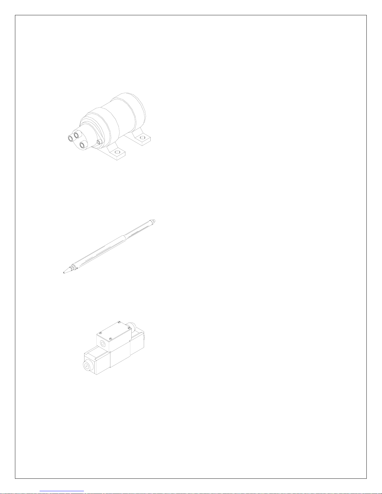
1.3.6 Reversing Pumpsets
Various sizes and types of Pumpsets are available which
connect into the vessel’s hydraulic steering system,
pumping oil on command from the Distribution Unit so as
to drive the steering cylinder to the required rudder angle.
The reversing motor Pumpset is only operation when
carrying out a rudder command. When the vessel is on
course the motor stops. A variable speed motor drive
adjusts maximum rudder positioning accuracy. Optional
solenoid valve controlled Pumpsets are available for use
on larger vessels. Construction is splashproof.
1.3.7 Linear Drive
A hydraulic cylinder is provided for driving the quadrant of
mechanical steering systems. The cylinder is driven by
one of the above Pumpsets and includes a small hydraulic
reservoir and bypass valve that frees the hydraulic system
when the Autopilot is not in use. This linear drive provides
a cleaner installation (being entirely below deck) and
delivers much more torque to the rudder than wheel driven
units. In case the mechanical steering should fail, the
cylinder provides a back up hydraulic steering.
1.3.8 Solenoid Valve Drive
On larger vessels the main hydraulic steering may be fitted
with a Solenoid Valve controlled power steering. In this
case the Autopilot does not need to be supplied with a
Pumpset drive unit since the Distribution Unit output can
be reconfigured with its board mounted DIP selector switch
to provide drive for steering solenoids having coil voltages
of 12 or 24 VDC.
Page 12

ComNav 1500 / 1510 Autopilot - 5 -
1.4 Accessories
1.4.1 NX2 Autopilot Instrument Control Head
Additional Autopilot Instruments Control Head (PN 20620044) may be added. They
are connected in a "daisy chain" fashion from one to the other, matching colors on
terminals. Control may be transferred from one instrument to another by simply
pressing any pushbuttons (except the OFF push-button) on the instrument where
active control is desired. All other inactive instruments will display the same
information as the active instrument, however in the lower display the text "passive"
will blink once every seven seconds.
1.4.2 NX2 Remote Control Instrument
The Remote Control Instrument (PN 20620048) is an instrument in itself that can
be set in either Autopilot mode to be used as an Autopilot instrument, or Instrument
mode displaying all information on the NX2 Network. The Network Remote Control
Instrument (PN 85006) can be used as a remote control for all instruments
connected to the Network. It is the ultimate NX2 instrument!
1.4.3 NX2 Analog Rudder Angle Indicator Instrument (RAI)
The Analog Rudder Angle Indicator Instrument (PN 20620037) indicates the rudder
angle (50°-- 0° -- 50°). This instrument is connected on the NX2 data bus cable as
per color codes.
1.4.4 NX2 Multi Control Instrument with Server
The NX2 Server is the heart of the NX2 Network to which transducers for speed,
depth, wind, compass and navigators are connected. The Multi Control is a multifunction instrument that displays a main and a sub-function, grouped into 4 pages
for speed, depth navigation and wind information. The Multi Control instrument and
the Server are the building components of the NX2 Network.
1.4.5 External Alarm Buzzer
An external alarm buzzer (PN 30620023) can be connected to the Server only.
When activated, provides a local alarm at the Control Head in case the Autopilot
falls off course, develops a fault or the helmsman should fall asleep. The buzzer
can be positioned where it may be heard such as in the Captain's cabin, when any
alarm is activated.
1.4.6 NFU Jog Lever
A Non Follow Up (NFU) jog lever (PN 20310002) may be connected through the
Autopilot to directly control the steering Pumpset in any mode except standby
mode. This is useful for docking or remote maneuvering such as required when
picking up crab traps etc. In any automatic pilot mode, the jog steering can be used
as a dodge function and when the jog lever is let go, the boat will revert to the
previous pilot course setting.
Page 13

ComNav 1500 / 1510 Autopilot - 6 -
2. INSTALLATION
2.1 General Comments
More than any other piece of marine electronics, reliable and accurate operation of
an Autopilot depends on correct installation. Please read and be sure you fully
understand the installation requirements before attempting installation.
The installation includes 6 major steps:
1.
Read the installation and operation manual completely
2. Plan where to install the equipment.
3. Run the cables.
4. Install the
3. Make the attachments needed for Pumpset and cylinder and
6. Learn the function
Before you begin drilling ... think about how you can make the installation as neat
and simple as your boat will allow. Plan where to position the transducers, Server
and instruments. Think about leaving space for additional instruments in the future.
transducers and instruments.
s and calibrate your system.
.
install them.
A few ”do nots” you should consider:
• Do not cut the cables too short. Allow extra cable length at the Distribution
Box (Servo Unit) so it can be disconnected for inspection without having to
disconnect all attached cables.
• Do not place sealant behind the display. The instrument gasket eliminates
the need for sealant.
• Do not run cables in the bilge, where water can appear.
• Do not run cables close to fluorescent light sources, engine or radio
transmitting equipment to avoid electrical disturbances.
• Do not rush; take your time. A neat installation is easy to do.
The following tools and materials will be needed:
• Wire cutters and strippers.
• Small and large Philips and small flat head screw driver.
• Hole saws: 63mm OD (2½") and 89mm OD (3 ½”).
• Drill bit for 5mm OD (1/4").
• Plastic cable ties
If you are doubtful about the installation, obtain the services of an experienced
technician.
Page 14

ComNav 1500 / 1510 Autopilot - 7 -
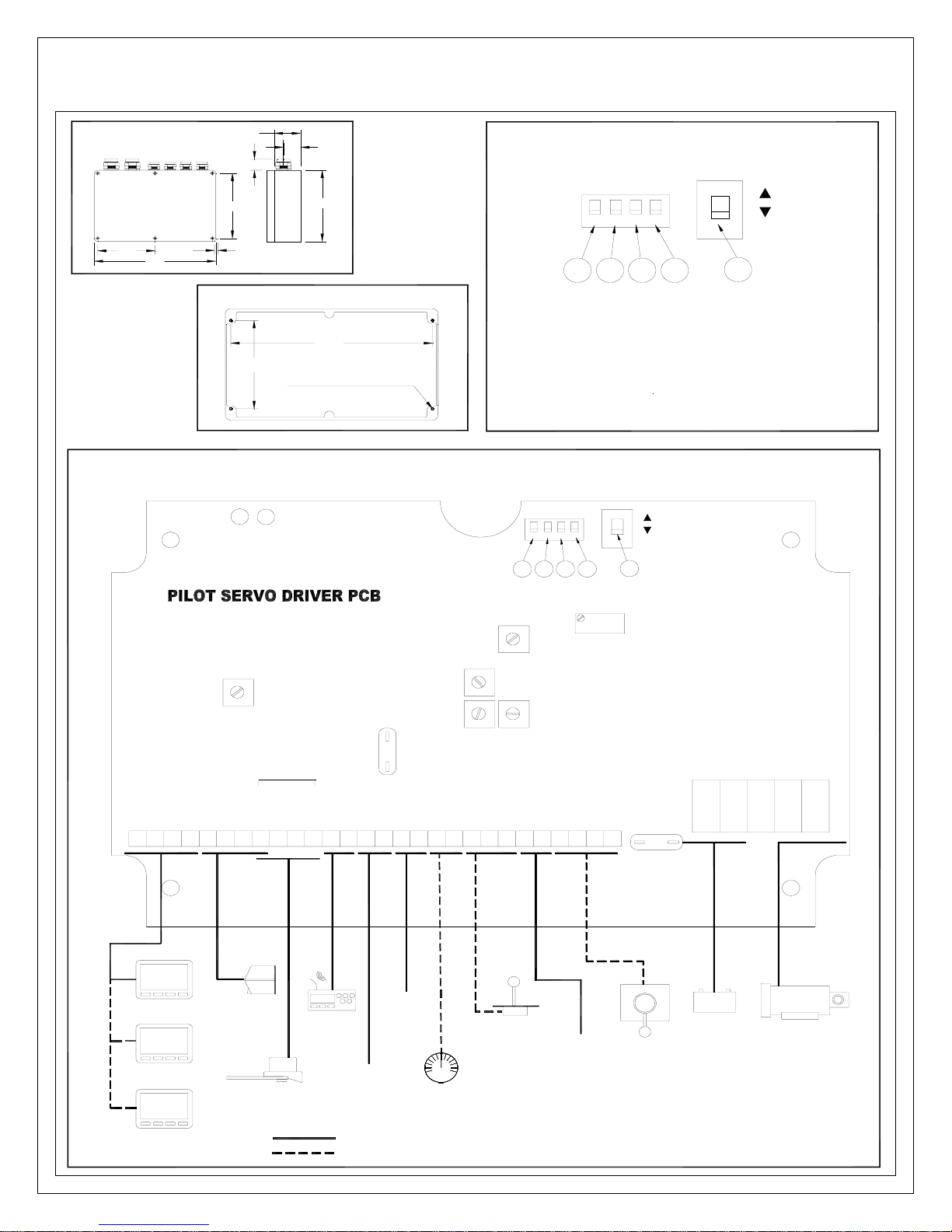
2.2 Distribution Unit 1500 & 1510
Location
The Distribution Unit must be mounted on a dry, flat and vertical surface below
deck, at least 500 mm (20") from radio receiving equipment. Since all wiring
originates at the Distribution Unit, it should be centrally located to minimize lengths
of wiring. It is most important to minimize the runs of power and motor leads since
voltage drop in these cables will reduce steering capacity.
Installation
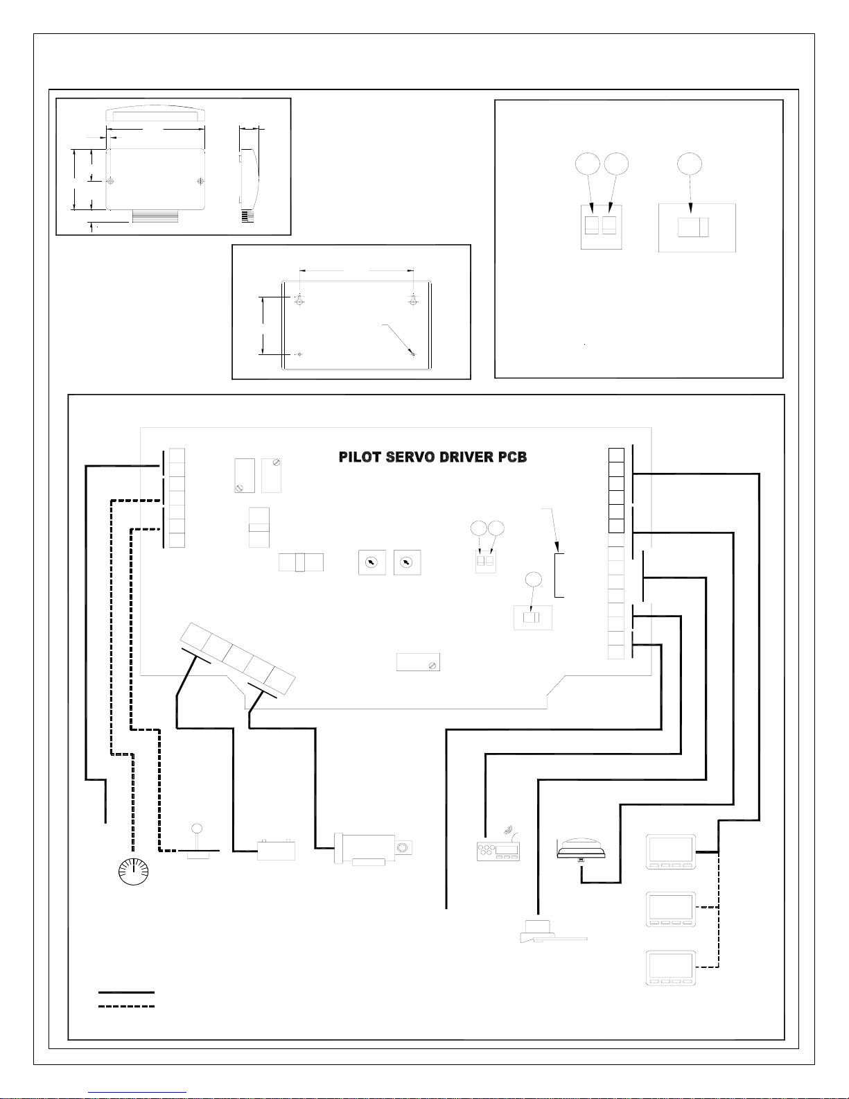
Note: The 1500 and 1510 Autopilots are designed for different applications:
The 1500 is designed as a Stand Alone System.
The 1510 is designed to work as part of a Network System, by connecting it to the
NX2 Network.
Place the adhesive drill template provided in the desired location for the appropriate
Distribution Unit and drill accordingly. (Reference the following pages). Remove the
template. To mount the Distribution Unit, remove the cover screws. The 4 inner
mounting holes are now exposed. Mount the Distribution Unit with 4 screws (not
supplied).
Note for the 1500 Distribution Box: If any waterproof cable glands do not have
cables inserted, install the short rubber plug provided in order to maintain water
tightness. If many options are connected and not enough glands are available, use
a separate junction box and route the excess wires through one large cable in one
of the large glands.
Note for the Autopilot Instrument / NX2 Network connection. If you want to run
the NX2 Network instruments separate from the Autopilot, do not connect green
wire to (pin 1) to the left in Distribution Unit. Instead insulate the green wire.
Wire thickness - Important! Use the following table to determine wire thickness.
Total distance from battery to Distribution Unit and distance from Distribution Unit to
Pumpset must be used to determine the wire thickness from the table.
Cable Length Maximum
(m) (ft)
Wire Size
2
(mm
)
Wire Size
(AWG)
3102.5 14
516 4 12
7.5 25 6 10
12 40 8 8
Make sure, that the wire size between the battery and the point where you will connect
the wire to the Distribution Unit is big enough to secure power supply to all other
connected electrical units on board. If you are in doubt, ask your local technician.
Page 15
ComNav 1500 / 1510 Autopilot - 8 -
4.1"
8.7"
2.2"
1.2"
5.3"
0.2"
A-1500 DISTRIBUTION UNIT TEMPLATE
5.7"
0.8"
DIP SWITCHES
UP
2
3
DOWN
1
4
12 43
1) Make sure it is in down position for reversing pumpset application,
up f
or solenoid valve operation.
24/32 VDC
12 VDC
5
2)Keep in down position.
3)Keep in down position. If using analog output interface (A1100),
k
eep in up position.
4)Keep in down position. If using full followup (FFU) tiller steering
option, keep in up position.
5)Set as per voltage application shown above.
5.56"
8.25"
0.20" DIA. , 4 OFF
FOR #8 TAPPING SCREW
** Make sure power is turned off to the pilot system prior to changing
dip switches.
A-1500 SYSTEM W IRING DIAGRAM (FOR REVERSING PUM PSET)
24/32 VDC
432
1
3421
DIP SWITCHES **
VR1
(ANTI-HUNT)
VR5
(DIG ITAL RA I
OFFSET)
FOR COMNAV
RUDDER FOLLOWER
INSTALLATION
(SEE SEC TION 2.5)
W
N
E
O
E
T
L
I
E
L
H
R
E
G
W
Y
W
D
N
L
E
E
E
I
R
H
S
G
D
E
E
O
L
T
L
I
E
I
L
H
E
H
W
Y
S
D
L
E
I
H
S
K
T
A
C
I
D
H
E
W
R
E
N
T
E
I
E
H
R
W
G
D
T
A
N
A
L
B
D
G
K
C
A
L
B
OFFSET
GAIN
E
S
5
U
F
A
D
T
A
D
D
N
N
+
G
+
G
VR3
(ANALOG RAI OFFSET)
VR4
VR2
(ANALOG RAI GAIN)
+
M
R
M
O
1
S
-
C
D
A
N
L
2
S
A
G
-
S
+
U
U
U
F
F
F
F
F
F
28272625242322212019181716151413121110987654321
12 VDC
5
VR6
(CURRENT LIMIT)
E
L
B
A
N
E
20
FUSE
)
)
2
1
D
D
I
I
O
O
N
N
E
E
L
L
O
O
S
S
(
Y
Y
R
R
E
E
T
T
T
T
A
A
B
B
-
+
2
1
(
N
O
M
M
O
C
3
2
1
R
R
O
O
T
T
O
O
M
M
5
4
CONTROL
HEAD
CONTROL
HEAD
CONTROL
HEAD
FLUXGATE
COMPASS
RUDDER FOLLOWER
& LINKAGE
NMEA
INPUT
(GPS)
PN: 29020007
BYPASS
VALVE
STEERING
NMEA
OUTPUT
BASIC SYSTEM COMPONENTS
OPTIONAL ACCESSORIES
RUDDER ANGLE
INDICATOR
JOG
BATTERY
REMOTE
WATCH
ALARM
**MAKE SURE POWER IS TURNED OFF TO THE PILOT
SYSTEM PRIOR TO CHANGING DIP SWITCHES.
VR5, VR6 - FACTORY SET - DO NOT ADJUST
LEVER
FOLLOW-UP
HYDRAULIC
PUMPSET
Page 16
ComNav 1500 / 1510 Autopilot - 9 -
DIP SWITCHES
21
24 12
UP
2
DOWN
pumpset application, up for solenoid valve operation.
1
0.3"
4.3"
2.2"
1.2"
6.5"
1.3"
A-1510 DISTRIBUTION UNIT TEMPLATE
4.75"
1) Make sure it is in down position for reversing
2)Keep in down position.
et as per voltage application shown above.
S
3)
Switch should be set to 12 fo r 12 VD C
application or set to 24 for 24 VDC application.
2.6"
Ø0.1 0", 4 OFF
FOR #6 TAPPING
SCREW
** Make sure power is turned off to the pilot
system prior to changing dip switches.
A-1510 SYSTEM WIRING DIAGRAM (FOR REVERSING PUMPSET)
1
6
+
1
7
GND
1
8
+
1
9
-
2
0
S1
2
1
COM
2
2
S2
1
VR2
VR3
5 AMP FUSE
E
T
T
A
B
3
15 AMP FUSE
Y
R
N
O
M
M
O
C
O
M
4
VR4 VR1
)
1
1
R
O
E
T
L
O
S
(
5
)
D
I
2
O
D
I
N
2
O
R
N
O
E
T
L
O
O
M
S
(
Y
R
E
T
T
A
B
+
-
2
FOR COMNAV
RUDDER FOLLOWER
INSTALLATION
(SEE SECTION 2.5)
12
2
1
DIP
SWITCHES **
VR6
24 12
GREEN
YELLOW
WHITE
SHIELD
GREEN
YELLOW
WHITE
SHIELD
3
WHITE
BLACK BLACK
RED
DATA
GND
DATA
GND
1
2
3
4
5
6
7
8
SHIELD
9
WHITE
1
0
GREEN
1
1
1
2
1
3
1
4
1
5
3
BYPASS
VALVE
JOG
STEERING
RUDDER ANGLE
INDICATOR
**MAKE SURE POWER IS TURNED OFF TO THE PILOT
SYSTEM PRIOR TO CHANGING DIP SWITCHES.
VR6 - FACTORY SET - DO NOT ADJUST
BASIC SYSTEM COMPONENTS
OPTIONAL ACCESSORIES
BATTERY
PN: 29020007
HYDRAULIC
PUMPSET
NMEA
OUTPUT
NMEA
INPU T
(GPS)
RUDDER FOLLOWER
& LINKAGE
FLUXGATE
COMPASS
CONTROL
HEAD
CONTROL
HEAD
CONTROL
HEAD
Page 17

ComNav 1500 / 1510 Autopilot - 10 -
2.2.1 Distribution Unit Connections
Distribution Unit connections should be according to the System Wiring Diagram
provided and in addition, the following points:
2.2.2 Safety Switch
Important! An external safety switch or circuit breaker (not supplied) should be
installed in line with power input. Make sure it is rated greater than or equal to 25
Amps.
This switch will serve as your Autopilot ultimate safety OFF switch.
2.2.3 DIP Switches
The main circuit board has 2 DIP Switches, which must be pre-set during
installation to suit the installed configuration.
Important! With power turned off to the system, do the following:
Locate DIP Switch for 12 or 24/32 VDC voltage and make sure it is set to the
a)
voltage supply connected.
b) Locate DIP Switch for ”Solenoid Valve” or ”Pumpset” and make sure it is
the type of drive you have installed.
set to
2.2.4 Trim Potentiometers
If an external Rudder Angle Indicator is fitted to a 1500 Distribution Unit, it can be
calibrated with the 2 trim potentiometers as indicated on drawing. Adjust VR3
labeled offset, for rudder center and VR2 labeled gain, for maximum deflection.
Note that this is just to calibrate an external Rudder Angle Indicator Instrument. The
NX2 instruments must be calibrated by changing the rudder angle transmitter arm
length.
Page 18
ComNav 1500 / 1510 Autopilot - 11 -
2.3 Control Head
Location
The Control Head is waterproof when gasket mounted to a flat surface. It should be
mounted near the steering position for ease of visibility and transfer from manual to
automatic.
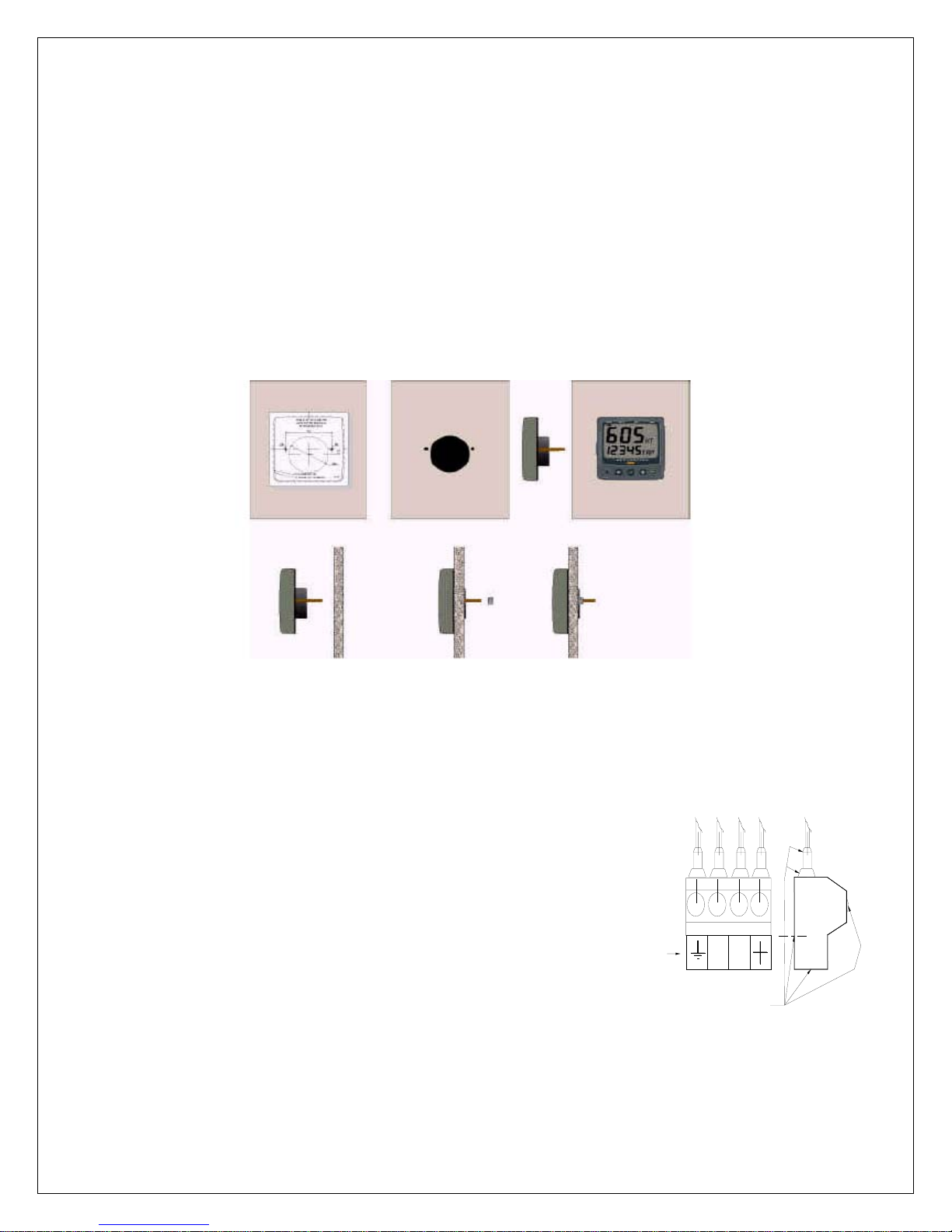
Installation
Place the adhesive drill template on the desired location for the Control Head. Drill
the 2 holes using a 5mm (1/4") drill for the two pin bolts. Use a 63mm (2½") hole
saw to machine the clearance hole for the Control Head connection socket.
Remove the template.
• Screw the two pinbolts to the instrument.
• Put the instrument in place.
• Screw the two nuts from the back.
Note! The two nuts should only be hand tightened. Do not use a wrench.
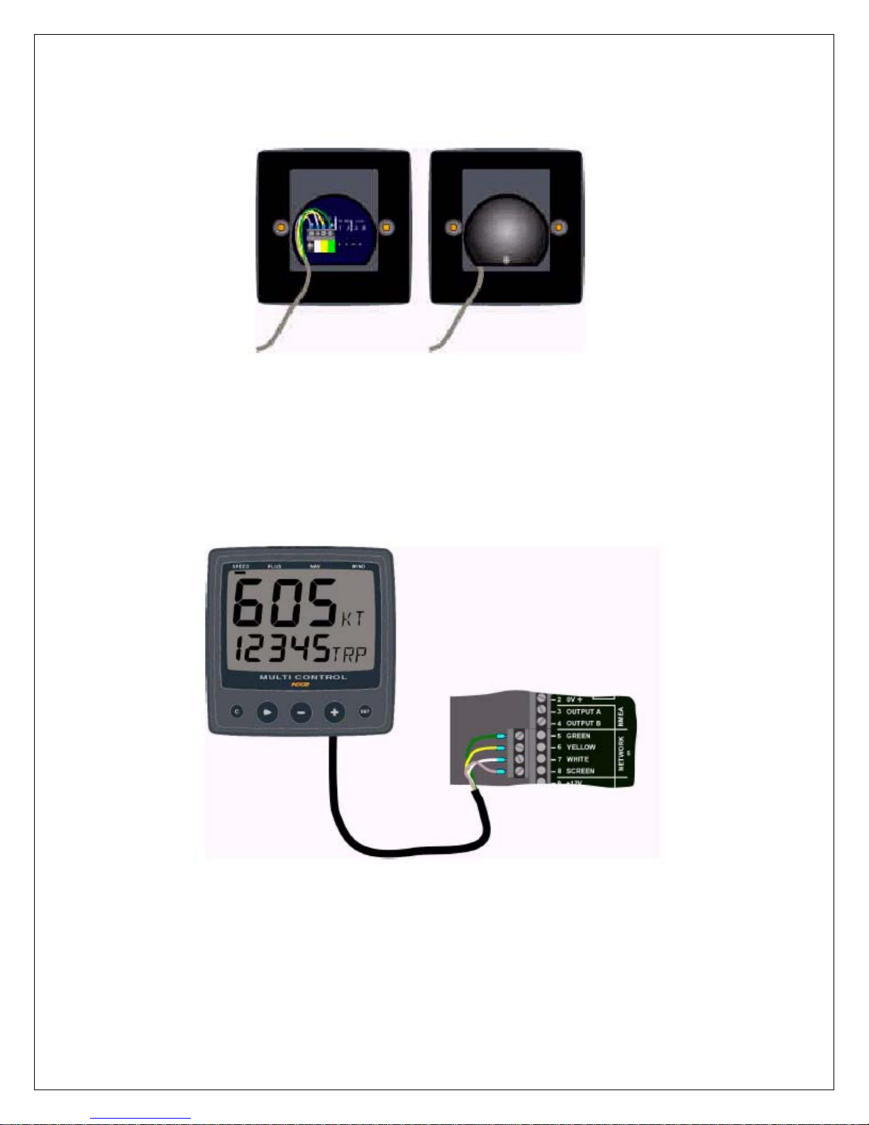
• Run the NX2 Network cable from the Distribution Unit
to the Autopilot Instrument Control Head. Connect to
terminals #1, 2, 3 and 4 (see System Wiring
Diagram).
• If you want to cut the NX2 Network cable to length,
disconnect 4-pole jack plug and cut the cable. Peel
off about 35 mm (1,4") of the cable insulation.
Remove about 6 mm (1/4") from the 3 isolated wires
GROUND
SYMBOL
(the 4th wire is an earth / screen).
Attach the 4 cable protectors to the wires using a pair
SILICONE GREASE
of flat pliers.
• Connect the 4 cable protectors to the 4-pole jack plug
as shown.
• Apply silicon grease on all locations as shown.
This must be done to avoid corrosion.
Page 19
ComNav 1500 / 1510 Autopilot - 12 -
• Apply silicon paste to the instrument connection pins at the back of the
Instrument. Press the jack plug onto the instrument pins. Press the cable in to the
cable leads.
• Secure the back cover with the screw.
All NX2 instruments are connected directly to the NX2 Network in a daisy chain.
They all use the same colour coded 4-pole jack plugs.
Page 20

ComNav 1500 / 1510 Autopilot - 13 -
2.4 Flux Gate Compass
Location
Compass location is most critical. This compass operates with an automatic
deviation feature. Best performance will be obtained if mounted at the center of
pitch and roll, in order to minimize undesirable accelerate which can degrade
compass stability. On most vessels this would be about 1/3 forward, on the
centerline and approximately at sea level. Various obstructions or magnetic
interference may exist at this ideal location and a reasonable compromise is
acceptable in establishing the exact location. The fore-aft arrow on the compass
should face forward and parallel to the boat centerline. If this is not possible, the
compass error resulting (lubber line error) may be corrected after Autodeviation has
been performed. The compass should be mounted with the cable outlet at the
bottom (See diagram on following page).
The following safe magnetic distances should be maintained where possible:
OBJECT SAFE DISTANCE
Ft. m.
Main Engine 7 2
Radar Magnetrons 5 1.5
Horizontal and Vertical Steel Plates, Tanks 3 1
High Power Electric Motors (bilge pumps,
refrigerators)
HF or VHF Antennas 10 3
High Current DC wires 3 1
Magnetic meter movements and loud speakers 3 1
Large bolts or fasteners 2 0.6
31
The above may not always be possible to maintain due to problems unique to each
vessel. If in doubt, check for local magnetic disturbance using the Installation
procedure.
Steel vessels are a special case and an experienced compass adjuster should be
consulted since the automatic compass compensation only corrects for horizontal
errors and significant deviation from vertical fields such as Vertical Heeling Error
can occur.
Page 21
ComNav 1500 / 1510 Autopilot - 14 -
p
Installation
At the dock, hold the small pocket compass (supplied) in the proposed compass
location, and while keeping it pointed in one direction, slowly move it up and down
over about 3ft (1m). Then move it slowly fore-aft and athwartships over about 3ft
(1m) while keeping it on the same bearing and at the proposed mounting height. If
the compass heading does not change by more than 30°, the location is probably
acceptable. Another test is to temporarily mount a fluid compass at the proposed
Autopilot location and then turn the vessel slowly while comparing the compass
heading against the corrected main steering compass heading. If differences are
less than 30°, the automatic compass compensation will operate satisfactorily. The
automatic deviation may correct for much larger errors, but best Autopilot response
will be achieved if a location with low magnetic interference is chosen.
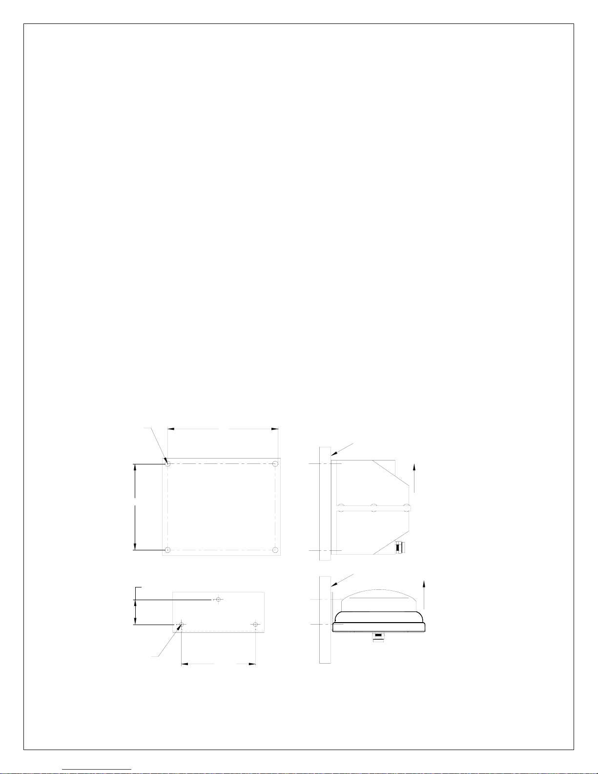
• 45° Compass: With cable outlet at bottom, place the compass on a flat vertical
surface and mark the 4 mounting holes. Drill accordingly and mount with
stainless steel fasteners.
• 35° Compass: With cable outlet at bottom, place the bracket on a flat vertical
surface and mark the 3 mounting holes. Drill accordingly and mount using
stainless steel fasteners.
For Both
1500 & 1510
Auto
ilots
Connect the compass cable to the Distribution Unit terminals #5, 6, 7and 8,
matching the colors as marked on the circuit board (see System Wiring Diagram).
COMPASS MOUNTING DIMENSIONS
Ø0.19"
(5mm)
4 HOLES
4"
1.56"
5"
VERTICAL BULKHEAD
VERTICAL BULKHEAD
UP
45° COMPASS TRANSDUCER
FLUID DAMPED FLUX GATE
UP
35° COMPASS TRANSDUCER
FLUID DAMPED FLUX GATE
Ø0.19"
(5mm)
3 HOLES
3.48"
Page 22
ComNav 1500 / 1510 Autopilot - 15 -
2.5 Rudder Follower & Linkage
Location
The Rudder Follower is used to transmit the position of the rudder back to the
Autopilot. It should be connected to whatever parts of the steering system the
Autopilot controls. Normally, this will be the vessel’s rudder. However, if the vessel
has 2 stage steering, where the Autopilot drives a control or servo ram, the Rudder
Follower should be mounted to the servo ram rather than to the rudder. If the
Rudder Follower is connected directly to the rudder in this case, uncontrollable
hunting of the rudder will result.
Normally the Rudder Follower is mounted in the stern of the vessel, close to the
rudder post. A mounting base may have to be fabricated to position the Rudder
Follower properly. Mount the follower in a location where the possibility of damage
from any equipment stowed in the area is minimized.
Installation
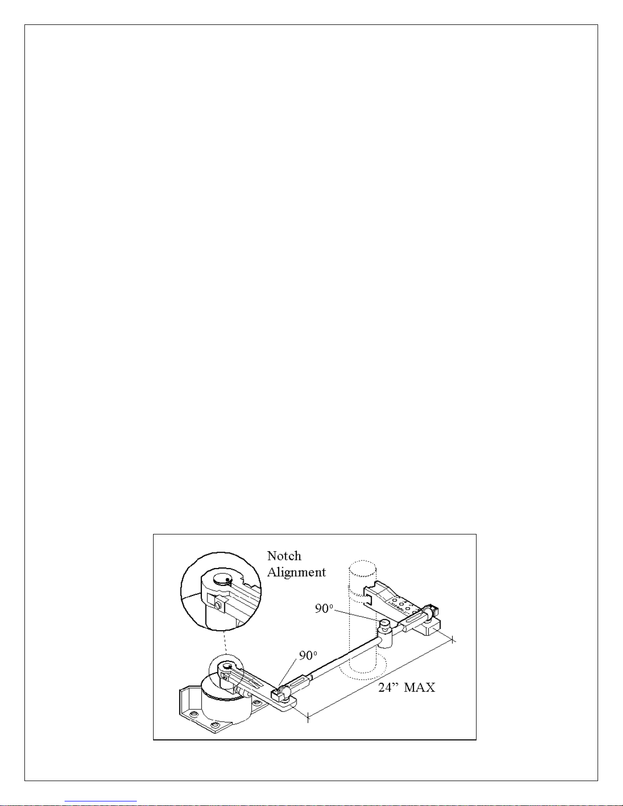
Mount the Rudder Post Arm on the rudder post using a stainless steel band clamp
(not supplied). Bolt the ball joint to the hole in the Rudder Post Arm corresponding
to the diameter of the Rudder Post in inches, making sure the ball is facing
upwards. Mount the Rudder Follower so that the Rudder Follower Arm is the same
height as the Rudder Post Arm. The Rudder Follower is centered when the arm
is directly above the cable gland (see illustration below).
The distance between the centerline of the Rudder Post and the Rudder Follower
must not exceed 24 inches. Make sure that the ball joints on the Rudder Arm and
Rudder Follower arm are facing upwards as shown in illustration. Snap the rod
assembly onto the ball joints. Be sure to close the release clamps on each socket.
Refer to illustration, and adjust the length of the rod to get the correct geometry with
the rudder dead-ahead.
Page 23
ComNav 1500 / 1510 Autopilot - 16 -
If the locking screw in the Rudder Follower arm has been loosened, or the arm
removed from the Rudder Follower, re-attach the arm and check the potentiometer
center position. When the rudder is dead-ahead, the electrical resistance between
the black and green wires and the white and green wires should be equal (approx.
600 ohms each).
Be careful to check the installation for any mechanical obstructions or binding of the
linkage, and correct it now, before it becomes a problem.
The Rudder Follower is supplied with approximately 15.5m (50’) of cable. Run the
cable from the Rudder Follower towards the SPU, ensuring that a hose or conduit
protects it wherever it passes through fish or cargo holds, or any other area where
it could be damaged.
If the length of cable supplied is too short to reach all the way to the SPU, obtain a
terminal strip and sufficient additional cable from your dealer. Mount the terminal
strip in a convenient DRY location.
Connect cable to Distribution Unit terminals #8, 9, 10 and 11. Rudder Follower
Wires: shield to terminal #8 (Flux Gate shield), white to terminal #9 (marked red),
green to terminal #10 (marked white) and black to terminal #11 (marked black).
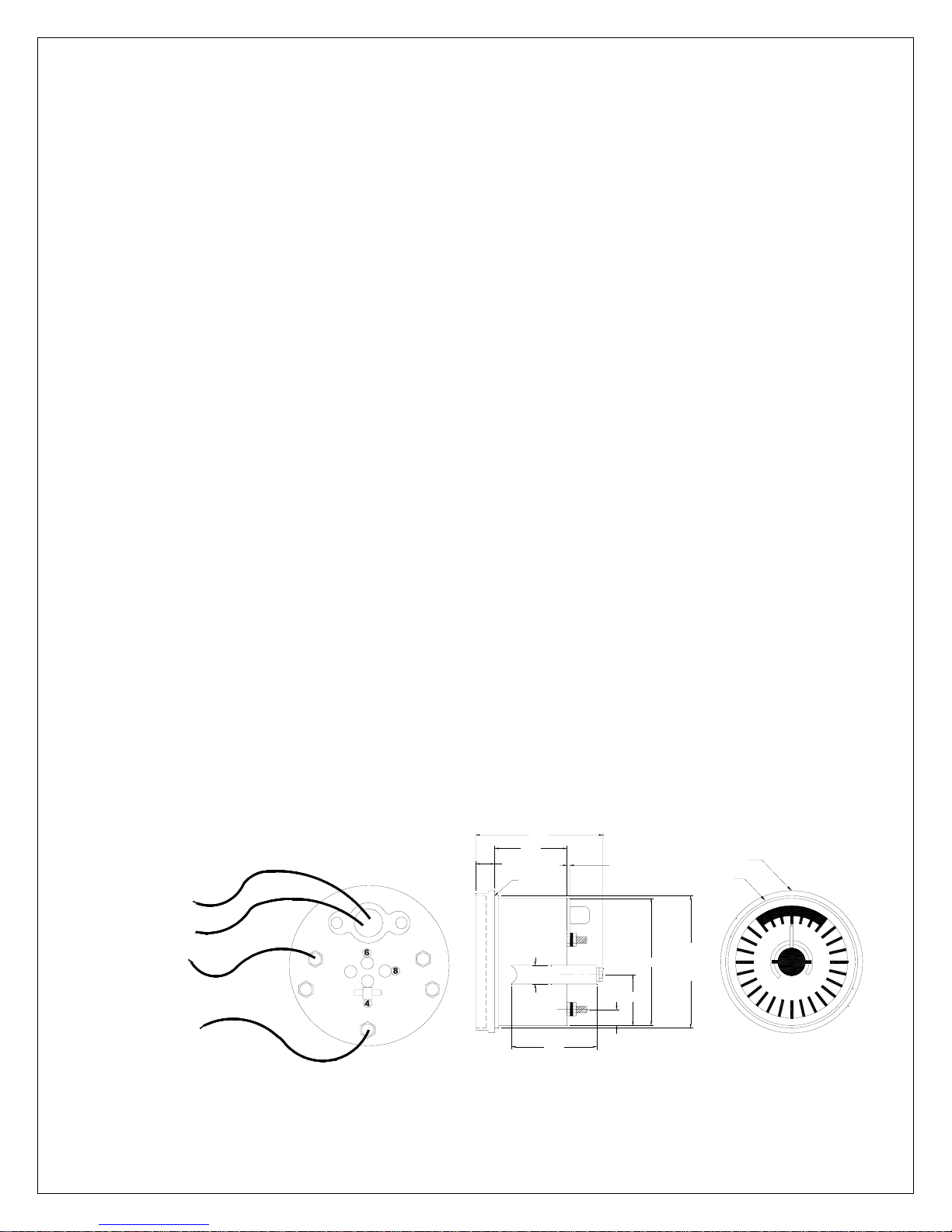
2.6 Analog Display Rudder Angle Indicator
Single or multiple analog display Rudder Angle Indicator repeaters can be added
as per the System Wiring Diagrams. If the rudder direction indication is reversed,
reverse the wiring connections at terminal #18 and #19 in the Distribution Unit. If a
ComNav Rudder Angle Indicator is fitted, adjustments of potentiometers VR2 and
VR3 on servo unit circuit board may be necessary. Potentiometer adjustment
details are outlined in Fine Tuning Section. If multiple Rudder Angle Indicators are
fitted, they must be wired in series.
BACKLIGHTING
SUPPLY
VOLTAGE
TERMINAL #18
TERMINAL #19
0.6"
3.7"
2.6"
O-RING
0.6"
2.4"
1/2"
CLEARANCE
Ø3.3"
1.2"
0.5"
CUT OUT
HOLE
Ø3.5"
Ø3.5"
Ø3.8"
10
20
30
40 40
10
20
30
Page 24

ComNav 1500 / 1510 Autopilot - 17 -
2.7 NMEA 0183 Compass Interface
For the 1500 Distribution Unit: Use the NMEA 0183 Compass Interface available
from ComNav. Wiring interconnection instructions are provided with the NMEA
0183 Compass Interface. Calibration parameter “CAL c6” can be used to adjust for
heading offsets.
For the 1510 Distribution Unit: the NMEA 0183 Output Compass can be
connected directly to terminals #14 and #15.
2.8 LFU101 Full Follow Up (FFU) Tiller Steering
If you do not have a Full Follow Up (Tiller) lever, go to next item. The FFU steering
control lever or knob can be used to maneuver the vessel. The FFU steering will
control the rudder to the angle commanded by the follow up control lever or knob.
The DIP Switch on the servo until circuit board must be set up correctly to use this
function. The use operation and instruction manual for the FFU steering lever or
knob control is provided with the unit. The FFU steering feature is not available with
the A-1510 Distribution Unit.
Installation
The jog switch should be wired at terminals #20, 21 and 22 in the Distribution Unit.
If using a ComNav Jog Lever, the white wire from the Jog Lever should be
connected to terminal #20 of the Distribution unit. The green (common) wire of the
Jog Lever should be connected to terminal #21, and the black wire should be
connected to terminal #22. Additional jog levers may be added to the system by
electrically wiring them in parallel to terminals #20, #21 and #22 of the Distribution
Unit.
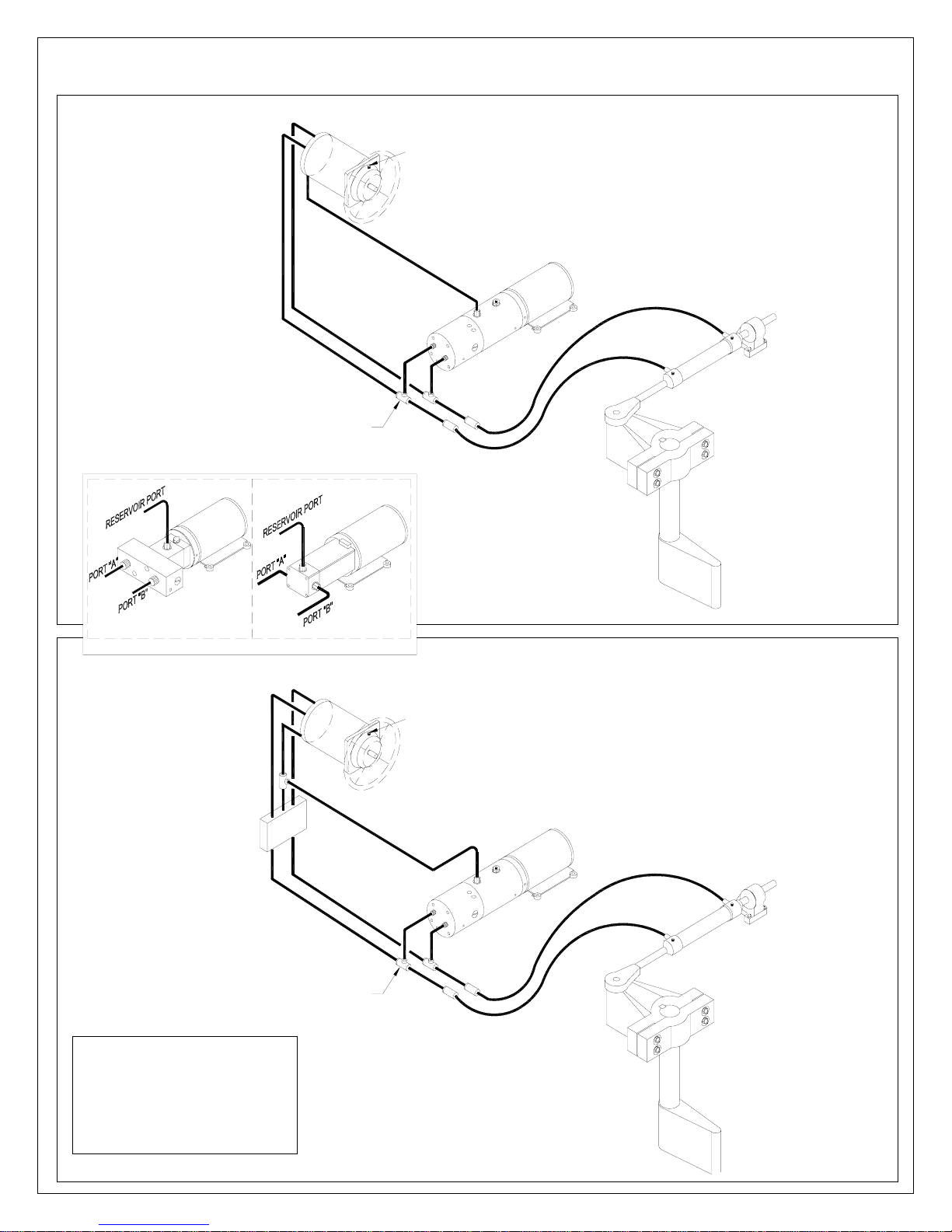
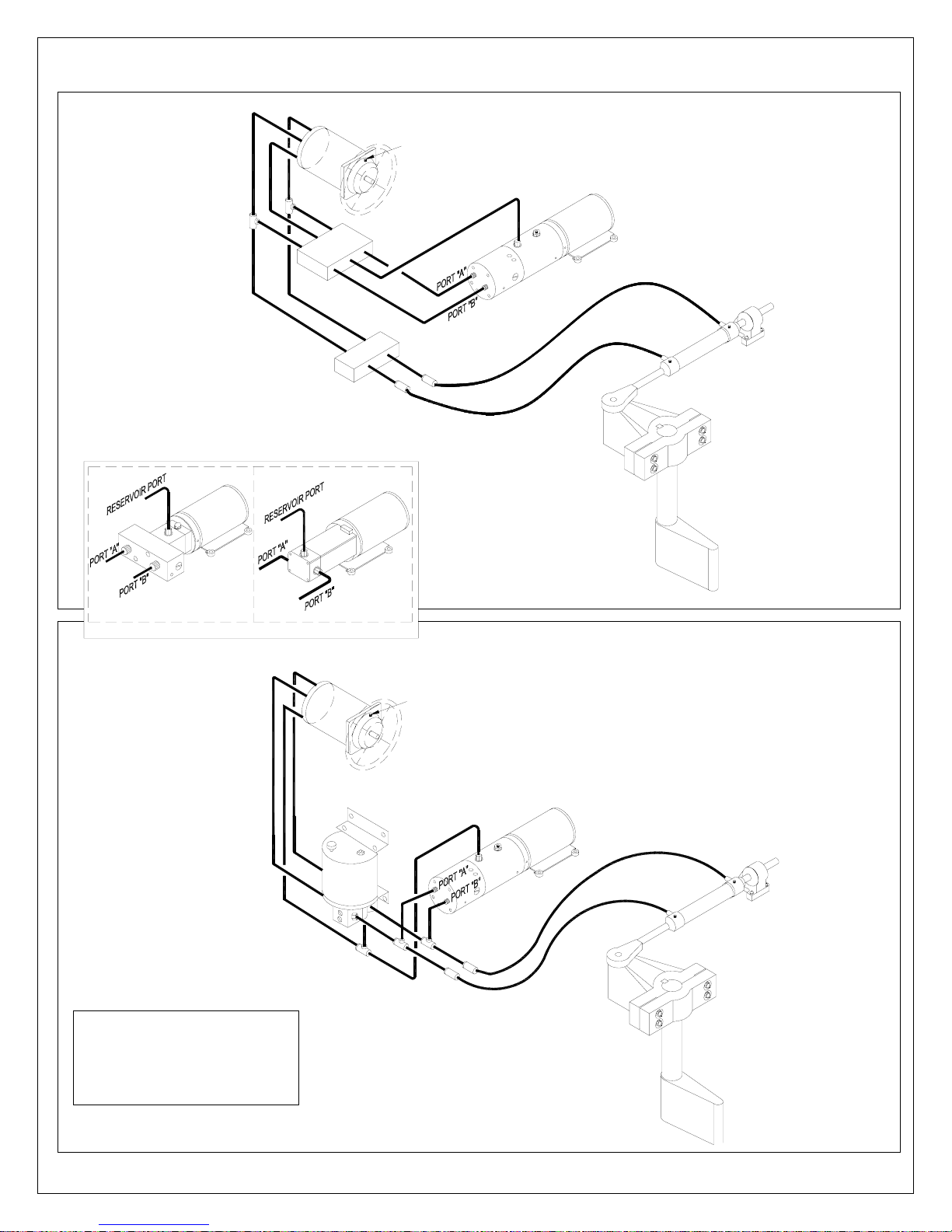
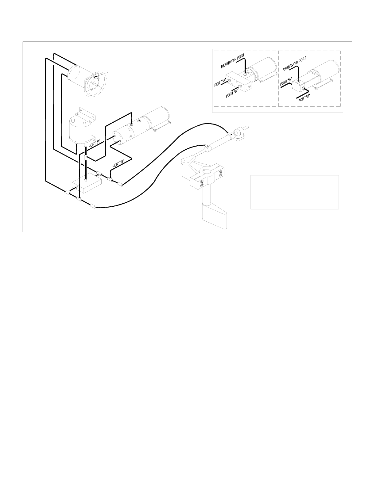
2.9 Reversing Pumpsets
Pumpsets should be connected into the vessel’s hydraulic steering system
according to piping schematics shown on the following pages. Most multiple station
steering systems have lock valves, which automatically isolate stations from each
other and from the Autopilot Pumpset. Where a lock valve is not fitted, it should be
obtained from ComNav and installed to isolate the helm. The Pumpset is
splashproof and should be mounted in a cool dry location, which minimizes
hydraulic piping and wiring runs.
Reference the following 3 pages for various hydraulic steering systems
complete with required fittings.
Page 25
ComNav 1500 / 1510 Autopilot - 18 -
Helm
Pump
TEE FITTING MUST BE
INSTALLED POINTING
UPWARDS AS SHOWN.
Filler vent plug
R
E
S
E
R
V
O
G
R
A
D
U
A
L
R
I
R
P
O
R
T
I
S
E
Pumpset
Steering
Cylinder
Tiller
OPTION PF0.3 PUMPSET
ComNav PV Series Pumpset
with Teleflex 250V & 275V
systems. Mount Teleflex
Uniflow Valve at least 6' (2m)
from helm pump.
OPTION PV1.4 PUMPSET
Helm
Pump
G
R
A
D
U
A
L
R
TEE FITTING MUST BE
INSTALLED POINTING
UPWARDS AS SHOWN.
I
S
E
Filler vent plug
O
P
R
I
O
V
R
E
S
E
R
Rudder
T
R
Pumpset
Steering
Cylinder
Tiller
Rudder
Page 26
ComNav 1500 / 1510 Autopilot - 19 -
Helm
Pump
Filler vent plug
OPTION PV1.4 PUMPSETOPTION PF0.3 PUMPSET
TELEFLEX
HV4151 VALVE
TELEFLEX
UNIFLOW
VALVE
S
I
Pumpset
E
T
R
O
P
R
R
I
L
O
A
V
U
R
D
E
A
S
R
E
G
R
H
T
I
W
Steering
Cylinder
Tiller
Rudder
ComNav PV Series Pumpset
with Hynautic pressurized
Reservoir systems. 1B 251,
1B 511, 1B 231, 1B 531.
Helm
Pump
Filler vent plug
T
R
O
P
R
I
O
V
R
E
S
E
R
Pumpset
Steering
Cylinder
Tiller
Rudder
Page 27
Helm
Pump
Filler vent plug
T
OR
P
R
I
O
V
R
E
S
E
R
ComNav 1500 / 1510 Autopilot - 20 -
Pumpset
OPTION PV1.4 PUMPSETOPTION PF0.3 PUMPSET
Steering
Cylinder
Tiller
Rudder
ComNav PV Series Pumpset
with Hynautic pressurized
Heavy Duty systems. M2
1150, MS 1175, MS 1200,
MS 2175, MS 2200.
2.10 Installing Fittings
It is recommended that all fittings be installed and aligned in the Pumpset before it
is mounted. The type of fitting required i.e., straight or 90° will depend on the
mounting position of the pump and the location of piping. Refer to “Mounting the
Pumpset” for permissible orientations. All ports on the Pumpset are ¼” NPT. Pipe
sealant or Teflon tape is required on all male pipe thread fittings. Be certain to keep
the sealant or tape at least two threads away from the starting threads to prevent
shredded tape or sealant from contaminating the system. The tube fittings selected
must be suitable for the tubing size used. 3/8” OD (outside diameter) or equivalent
is recommended.
2.11 Mounting the Pumpset
The Pumpset may be mounted horizontally (motor feet down) or vertically with the
pump positioned above the motor. Be certain to leave adequate space to access
the bleed fitting and flow-adjustment nut.
Four #10 screws and washers are required to hold the Pumpset to the mounting
surface.
Page 28
ComNav 1500 / 1510 Autopilot - 21 -
2.12 Piping the System
3/8” OD copper tubing suitable for a working pressure of 1,000 psi or equivalent is
recommended for all connections. Flexible hose may be used but must have a
rated working pressure of 1,000 psi.
2.13 Filling the System
Once the main steering system has been filled, open the Pumpset bleed screw
(labeled on top of Pumpset), two complete turns. Wait until clear oil, void of any air,
exits the bleed fitting. Re-secure the bleed screw. Be certain that the flow adjusting
wheel is set at the maximum flow position if applicable. Top up the uppermost helm
pump or reservoir, if necessary. Once the cylinder responds instantly, most of the
air has been removed and the system is usable. The remaining air trapped in the
system will vent automatically with use. Refill the steering system reservoir as
necessary with oil as recommended by the steering manufacturer. Where no
recommendation is available use hydraulic oil of viscosity grade ISO 32.
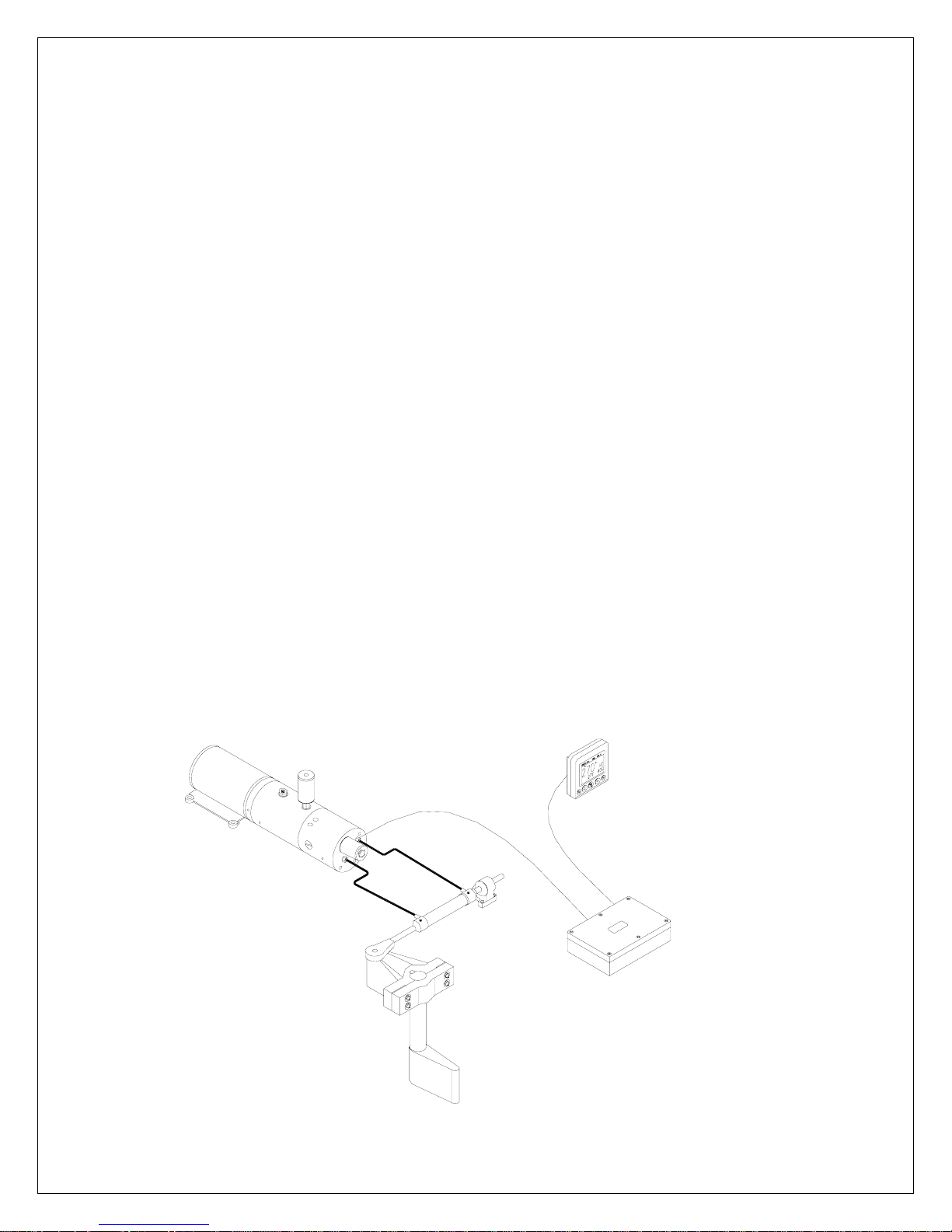
2.14 Linear Drive
The Linear Drive is only fitted on vessels with mechanical steering. The Linear
Drive consists of a hydraulic cylinder, which is connected to the mechanical
steering system to provide rudder steering drive for the Autopilot. A hydraulic
Pumpset is connected to the steering cylinder. The Pumpset motor is driven
clockwise or counter-clockwise by the Autopilot to produce port or starboard
movement of the rudder. When the Autopilot is turned off, a solenoid operated
bypass valve opens, permitting hydraulic oil to shuttle from one side of the
hydraulic cylinder to the other, allowing the mechanical system to regain control.
PUMPSET
RESERVOIR
SOLENOID
BYPASS VALVE
AUTOPILOT
CONTROL HEAD
STEERING
CYLINDER
PILOT
DISTRIBUTION
BOX
Page 29
ComNav 1500 / 1510 Autopilot - 22 -
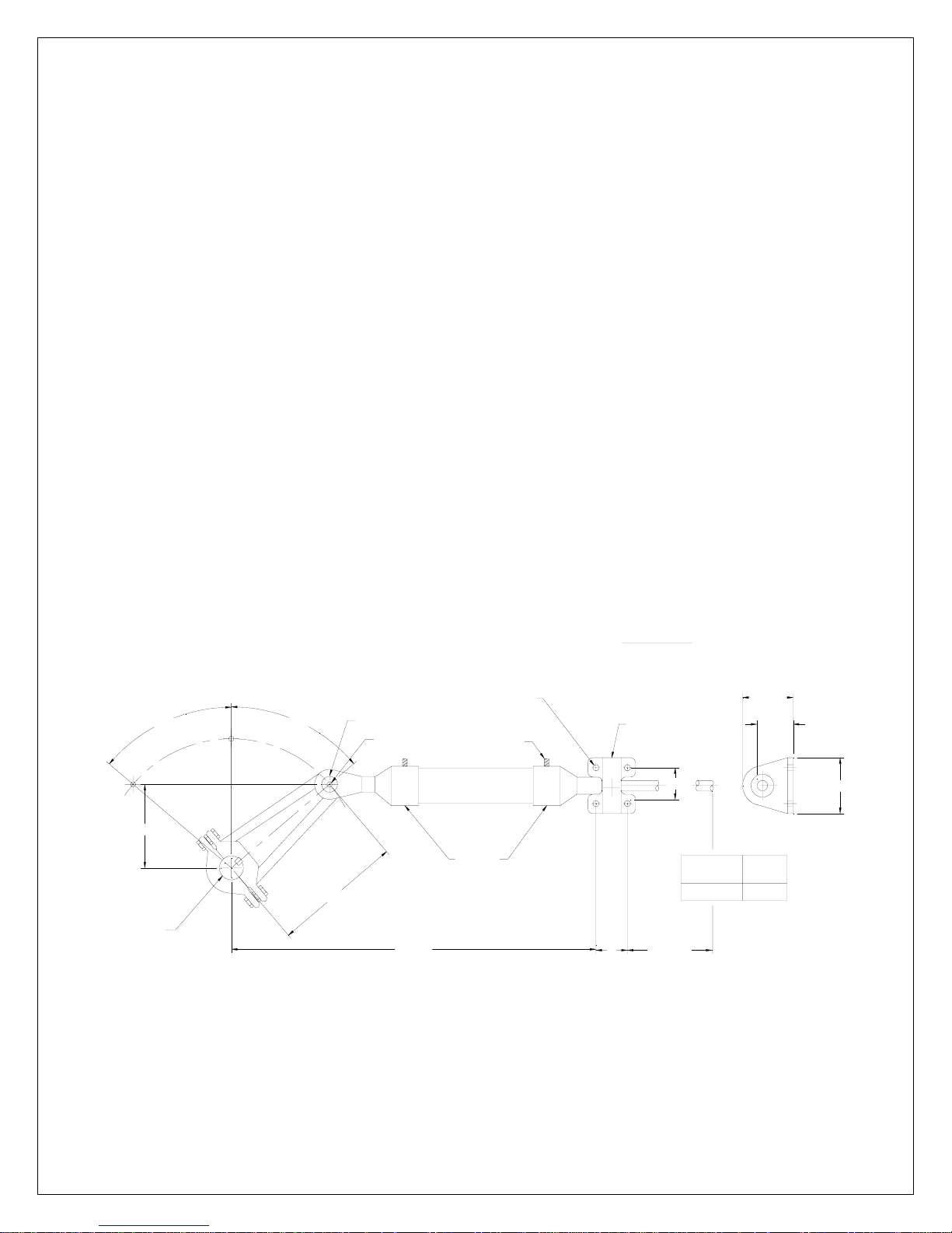
The hydraulic cylinder should be connected to the mechanical steering quadrant
with a ½” bolt and locknut through the quadrant arm and according to the geometry
shown below. A bridging bracket may have to be made across the quadrant arm if
a suitable connection point is not available. Alternatively, a separate tiller may be
connected to the rudderstock above or below the quadrant and the cylinder rod end
bolted to it. The cylinder has self aligning and self lubricating bearings making
alignment less critical and eliminating any maintenance. A strong support must be
made for the cylinder trunnion mount since forces of over 1600lb. (700kg) can be
developed. Connect the Pumpset to the cylinder with flexible hoses capable of
1000PSI (70 bar) working pressure. Fill the Pumpset reservoir with ISO32 or
equivalent following instructions in Dockside Setup. If operating in cold
temperatures, hydraulic oil of viscosity grade ISO 10 is recommended. The bypass
valve should be wired to the Distribution Unit terminals #16 and #17 as per System
Wiring Diagram. If the bypass valve wiring connection is reversed, it has no effect.
Installing reservoir into the Pumpset: Thread into reservoir port on the Pumpset. Do
not tighten reservoir by the reservoir body. Tighten by using the flats on the fitting at
the bottom of the reservoir.
3-3/4"
TILLER
Warning: Hand steering is not possible when an Autopilot Mode is selected with a
Linear Drive. The Autopilot must be turned off with the OFF button to disengage the
Autopilot drive and enable the mechanical steering. It is the skipper’s responsibility
to brief all crew members on this procedure.
DESCRIPTION
1-1/2 X 9 HYDRAULIC LINEAR DRIVE
SOLENOID BYPASS VALVE WITH RESERVOIR
Ø5/16
4 MOUNTING
50°
50°
CLEVIS
Ø1/2
BOLT DIAMETER
5-7/8"
18-1/2"
BOLTS
BLEED
FITTINGS
1/4" NPT
TRUNNION
2
2 6-15/16"
CYLINDER
MODEL
1-1/2 X 9
DISP
in
13.14
2-9/16
1-3/8"
2-3/4"
3
Page 30

ComNav 1500 / 1510 Autopilot - 23 -
2.15 Solenoid Valve Controlled Pumpsets
If the vessel is already fitted with a Solenoid Valve Controlled Pumpset having coils
for 12 or 24 VDC, connect the solenoid coils directly to the Distribution Unit as per
System Wiring Diagram provided. DIP Switch 1 is set in the “up” position (refer to
System Wiring Diagram).
Solenoid Valve Controlled Pumpsets should be adjusted to speeds of 14 seconds
from hardover port to hardover starboard or slower for maximum accuracy. Faster
hardover times will require increased anti-hunt settings to prevent hunting
(overshoot of the rudder).
To adjust anti-hunt setting, first complete procedures in Dockside Setup and Sea
Trails. Engage the Autopilot and with the Pumpset running, make 10 ° course
changes to port and starboard. If the rudder hunts (i.e. oscillates rapidly back and
forth during these course changes), gradually increase the anti-hunt control (i.e.
very slowly adjust VR1 trim potentiometer counterclockwise) until the rudder
remains stable. Do not increase the anti-hunt control any more than necessary as
this can begin to degrade course accuracy.
2.16 Accessories
Install any accessories as per instructions included with them and according to
wiring as shown in System Wiring Diagrams included in this manual.
When you finished the installation, perform the Dockside Testing routine.
Page 31

ComNav 1500 / 1510 Autopilot - 24 -
3. ADVANCED OPERATION
3.1 Adjusting Response (See Calibration Menus).
Note: the rudder [RUD] and counter rudder [CRD] settings are inter-related and
may effect the performance of each other. Setting by trial and error may be
required.
3.2 Rudder [RUD] Function
The most critical adjustment for good steering is the rudder. Too high a setting will
cause excessive amounts of rudder to be given that force the vessel to hunt rapidly
back and forth across the course. Too low a setting lets the vessel slowly fall of
course with repeated corrections required to get back on course. The rudder should
be set to the position where positive control of course is achieved without undue
activity. Run the vessel at its cruising speed and make a course change with the
keypad of 40°. The vessel should not overshoot by more than 3° to 4°. Adjust the
rudder until this is achieved.
3.3 Sea State [SEA] Function
The parameter is a combination of yaw dead-band (compass sensitivity) and
compass damping. The minimum setting may only be used under calm sea
conditions to avoid unnecessary rudder correction due to compass acceleration
errors. Smaller vessels and high-speed vessels, which are subject to more
acceleration in lighter seas, will have to use higher settings. Larger and more stable
vessels can use lower settings since there is less compass disturbance. The
factory default setting should work on most vessels in light to moderate sea
conditions. Following seas, no matter how rough, require lower settings to catch
course error trends quickly in order to minimize excessive yaw.
3.4 Counter Rudder [CRD] Function
This feature senses the rate of change of heading and gives additional rudder
corrections if the vessel is rapidly falling off course, and backs off the rudder as a
vessel approaches the desired heading. Its effect is to rapidly catch the tendency to
yaw in a quartering sea, provide initially high rudder control when making a large
course change and to decelerate the swing of the bow as vessel approaches the
desired course. When using this feature, course holding of heavy and difficult to
steer vessels is greatly improved. Insufficient counter rudder will allow the vessel to
overshoot on large course changes and too much will cause unnecessary rudder
corrections and a tendency to stop short of coming to a new course, requiring
several successive corrections before easing up to the new heading. To optimize
counter rudder, initially set it to minimum and adjust the rudder so that the vessel
responds smartly to a 40°-course change with less than 3° to 4 ° of overshoot.
Then increment the counter rudder one step at a time while testing 40 °-course
changes, until the vessel achieves an overshoot of 2° or less. Remember any air
in the hydraulic system will prevent precision control.
Page 32

ComNav 1500 / 1510 Autopilot - 25 -
3.5 Automatic Trim [ATC] Function
Automatic Trim Adjustment is not critical. It constantly compares the course set
against the course steered. If a persistent error exists due to wind, waves or
unbalanced forces (such as a single screw operation of a twin screw vessel), or an
off-center tow or weather helm on a sailing vessel, the automatic trim slowly applies
more rudder as necessary to reduce the error to zero. If the trim time is set too
high, it will take a long time to eliminate the course error. If it is set too low it can
start to degrade course stability. In general, longer trim times (higher settings)
should be set for large vessels and sailing vessels and shorter trim times (lower
settings) for small vessels and high speed planning vessels. The factory default
setting should be acceptable for all but extreme applications.
Page 33
ComNav 1500 / 1510 Autopilot - 26 -
4. AUTOPILOT INSTRUMENT CONTROL HEAD OPERATION
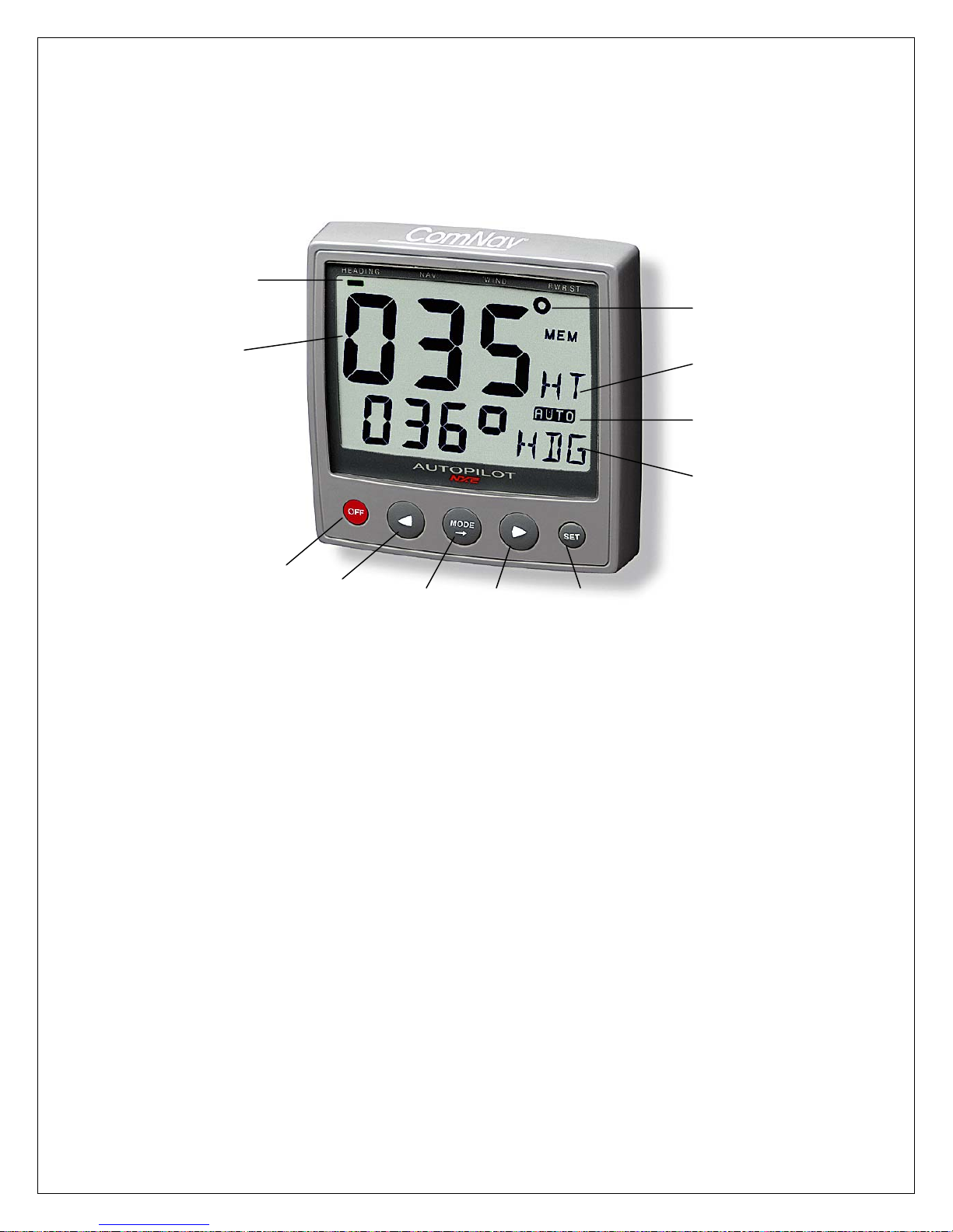
4.1 Instrument Overview
Page Arrow
Top-Line Heading
Reference
Course/Angle
OFF
LEFT MODE RIGHT SET
4.1.1 Instrument Display
The display consists of two lines, a top-line with 24mm (1”) digits and a lower-line
with 13mm (0.5”) digits.
4.1.2 Instrument Pages and Functions
The Autopilot instrument has its functions divided into 4 pages. The page
names are printed above the display:
Function
AUTO Mode On
Lower-Line
Function Text
HEADING (Compass), NAV (Navigation), WIND and PWR ST (Power steer)
The selected function is indicated by the page-arrow at top of the display.
4.1.3 Instrument Modes
Standby Mode: The instrument functions as a passive compass repeater.
Autopilot Mode: When any Autopilot function is activated.
Setup Mode: Allows calibrating your Network settings.
Edit Mode: Allows editing settings (when digits are flashing).
4.1.4 Power On/Off
You will switch on/off your NX2 instruments by using the instrument
switch on your electrical panel as the instruments have no separate
power on/off-button.
Page 34
ComNav 1500 / 1510 Autopilot - 27 -
4.2 How to Use the Push-Buttons
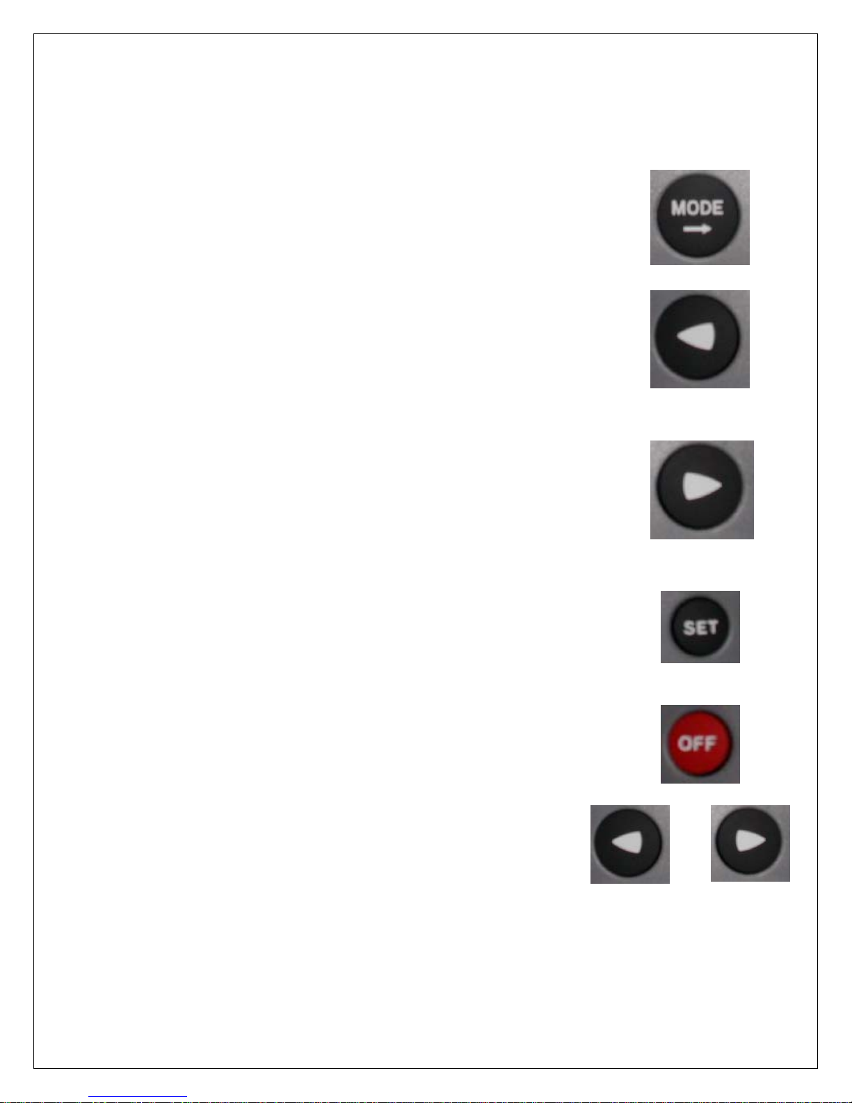
4.2.1 MODE
A press on MODE, moves one page to the right, indicated
by the page-arrow at top of the display.
In edit mode, a press on MODE moves the cursor one step
to the right. If the cursor is at the farthest right hand side,
a further press will cause it to rotate back to the left hand side.
4.2.2 LEFT
When the Autopilot is activated, a short press on LEFT
decreases the course by 1°, a long press decreases
the course by 10°.
In setup mode a press on LEFT moves to the previous setup
function. In edit mode a press on LEFT decreases a digit
by one.
4.2.3 RIGHT
When the Autopilot is activated, a short press on RIGHT
Increases the course by 1°, a long press increases
the course by 10°. In setup mode a press on RIGHT
moves to the next setup function. In edit mode a press on
RIGHT increases a digit by one.
4.2.4 SET
A press on SET engages the Autopilot in the selected steering
function (HDG, NAV WIND, or PWR ST).
In Setup Mode, a press on SET unlocks a digit to access edit
mode. When unlocked, the digits are ”active” (flashes) and can
be edited by pressing LEFT, RIGHT and MODE as required.
When finished editing, lock the digit by another press on SET.
4.2.5 OFF
A press on OFF turns the Autopilot.
4.2.6 Tack
A press on LEFT and RIGHT together, performs a Tack
when steering in wind mode.
&
Page 35
ComNav 1500 / 1510 Autopilot - 28 -
4.2.7 Setup Mode
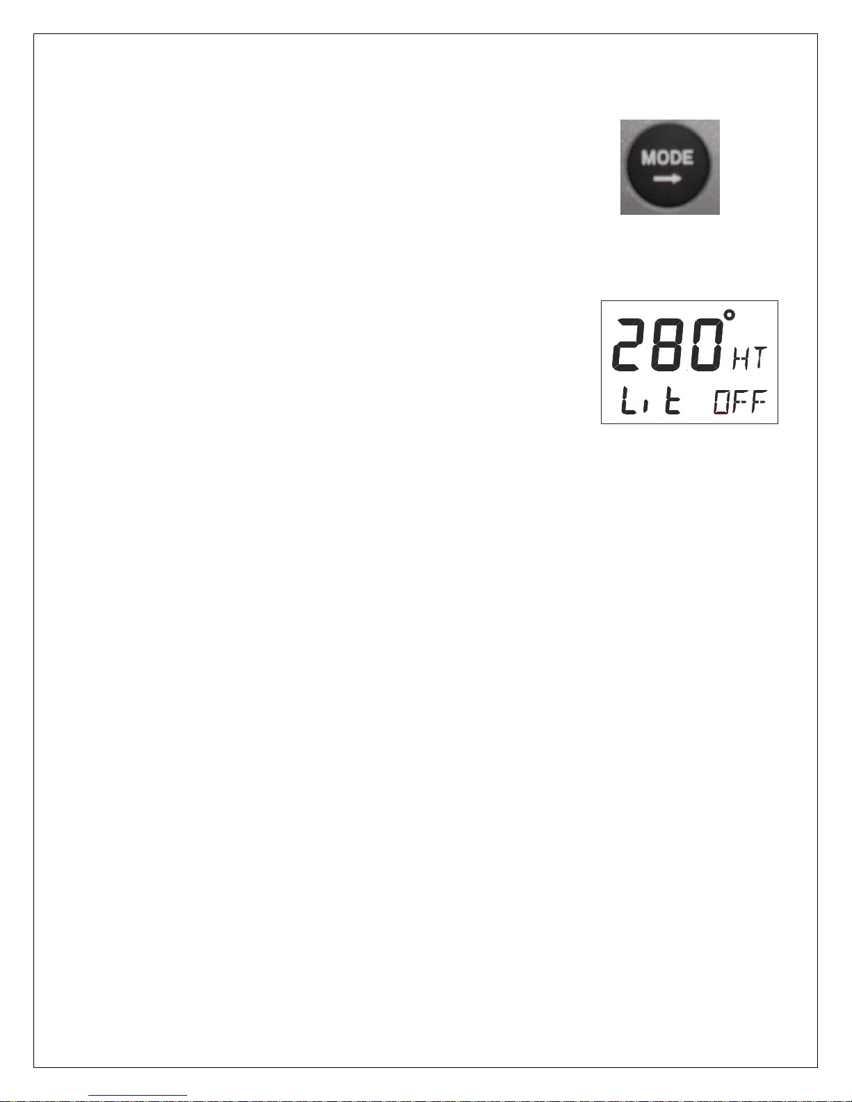
To access Setup Mode, press and hold MODE more than
2 seconds. [Lit OFF] flashes. To move to next setup group,
press MODE again.
To return to standby mode, press SET when the text return 2 seconds
[RET] is displayed.
4.2.8 Lighting
The instrument uses red back lighting for the display and the 4
push-buttons. The light can be set at 4 different levels.
To access the light control, press and hold MODE for more
than 2 seconds. The flashing text [Lit OFF] will be displayed
and the display will be lit momentarily.
To select between the 4 light levels [LOW], [MID], [MAX] and
[OFF], press RIGHT. To lock the selected level, press SET.
If the Autopilot is connected to an NX2 network, the selected
light level will be copied on to the Network. It is not possible
to reduce or turn off the lighting on an individual instrument.
Page 36

ComNav 1500 / 1510 Autopilot - 29 -
5. FUNCTION
5.1 Standby Mode
At power On, the Autopilot starts in standby mode and
operates as a passive compass repeater. No page-arrow
is shown at the top of the display.
The current course is displayed on the top-line.
The rudder angle is displayed on the bottom line.
In any function, the top-line displays the heading at all times.
5.2 Autopilot Mode
Prior to activating any automatic steering function, the boat
should be steadied on the desired heading and on track for
5 to 10 seconds to minimize large course changes when
activated. The Autopilot operates with course errors up to 90°,
and cross-track errors up to 2 nautical miles.
5.2.1 Activate Automatic Steering
To select a steering function, press MODE.
The page-arrow at top of the display indicates the selected page.
To activate the selected steering function, press SET when the
lower-line text is flashing.
The reversed lit text [AUTO] to the right and in the middle on the
display always confirms that an automatic steering function is
activated. The function text at lower-line to the right confirms which
steering function is activated, ex [HDG] for compass steering.
Note! If a page is not available, such as when no waypoint
information is programmed / activated or no navigator or wind
transducer connected, the page-arrow will not stop at that page.
5.2.2 Turn Off Automatic Steering
To turn off automatic steering, press OFF.
To turn off the Autopilot when you are in the process of changing
functions or are in setup mode, press and hold OFF for more than
two seconds.
Page 37
ComNav 1500 / 1510 Autopilot - 30 -
5.2.3 Automatic Steering by Compass
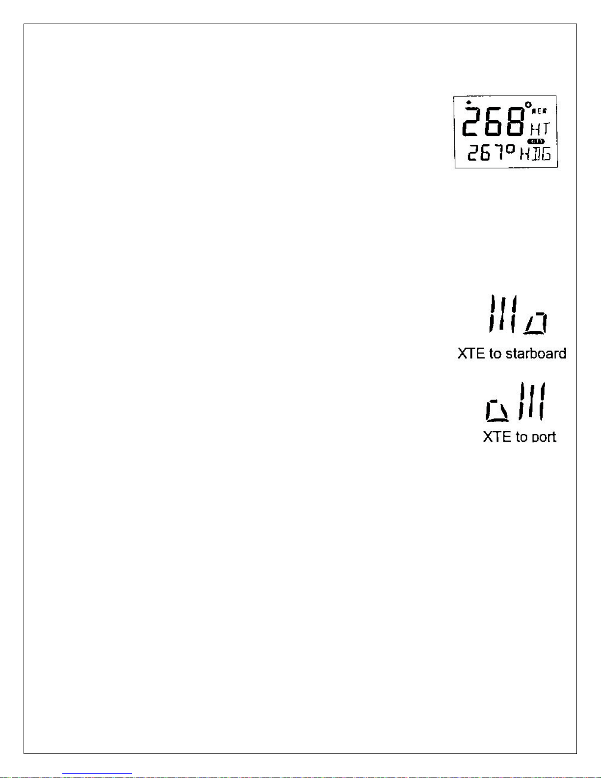
To select compass steering, press MODE until the page-arrow
appears under HEADING, and [HDG] is flashing on the lower-line.
Your present course is displayed on the top-line. This course will
become the reference course the Autopilot will keep when
automatic steering by compass is activated.
To activate compass steering, press SET when [HDG] is flashing.
The present heading now becomes the reference course and is
displayed on the lower-line to the left.
To change the reference course to port, press LEFT.
To change the reference course to starboard, press RIGHT.
A short press changes the course by 1°, a long press by 10°.
5.2.4 Automatic Steering by Navigator
Automatic steering by navigator is only possible if a navigator is
connected and it is navigating towards a waypoint.
To select steering by navigator, press MODE until the page-arrow
appears under NAV, and [NAV] is flashing on the lower-line. Your
present course is displayed on the top-line.
Caution! Before activating [NAV] steering, make sure your present
heading corresponds approximately with bearing to waypoint, and
that the cross track error is less than 2 Nautical Miles, because the
Autopilot will turn the boat towards the track line first and then onto
the heading set.
To activate NAV steering, press SET when [NAV] is flashing.
Bearing to waypoint or cross track error to waypoint are now
displayed on the lower-line to the left. To alternate the display
between bearing and track on the lower-line, press LEFT or
RIGHT.
Page 38
ComNav 1500 / 1510 Autopilot - 31 -
Caution!
The NAV function will automatically change course when the next
waypoint information is displayed and the helmsman should ensure that
there are no boats or other hazards on the new course as the waypoint
is changing. When using waypoint sequencing in a route list, it is
extremely important that the helmsman is at the steering position and
ready to override the pilot if the course change would cause collision
with other boats or objects.
Set all waypoints in navigators away from navigational hazards by at
least 100 meters as the boat may require this radius or more on
waypoint advance. The NX2 GPS Navigator will allow you to select a
route list with automatic sequencing, or with a confirming push-button
press for each waypoint.
5.2.5 Automatic Steering by Wind
Automatic steering by wind is only possible if the Autopilot is
connected to a NX2 Network with a wind transducer connected.
Note! The apparent wind speed must be more than 3 knots. If the
apparent wind speed falls below 3 knots, wind signals are disabled
and the Autopilot will maintain the current magnetic heading
reference instead.
Before activating wind steering, optimize your sail trim.
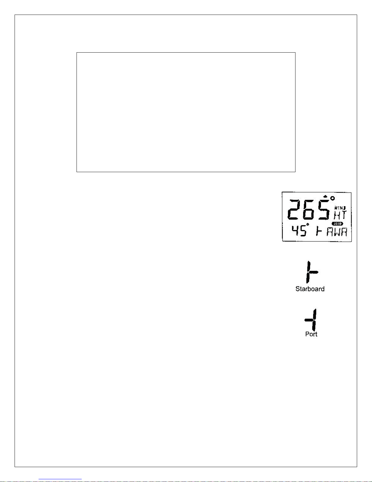
To select wind steering, press MODE until the page-arrow appears
under WIND, and Apparent Wind Angle [AWA] is flashing on the
lower-line. Your present course is displayed on the top-line.
To activate wind steering, press SET when [AWA] is flashing.
The present [AWA] now becomes the reference angle, and is
displayed on the lower-line to the left, followed by a sign to
describe wind from port or starboard.
To steer to port, press LEFT.
To steer to starboard, press RIGHT.
A short press changes the value by 1°, a long press by
10°.
When making large changes of over 30°, it may take about 1
minute for an accurate course to be re-established due to changes
in boat balance, which must be recognized by the automatic trim
function.
Page 39
ComNav 1500 / 1510 Autopilot - 32 -
To tack, press RIGHT and LEFT together and the boat will come
about the same apparent wind angle on the opposite tack.
Tack angles greater than 80° off the wind are not recommended
due to the possibility of an accidental gibe.
Warning! Pressing for a tack when the wind is abaft the beam will
result in a gibe!
5.2.6 Power Steering
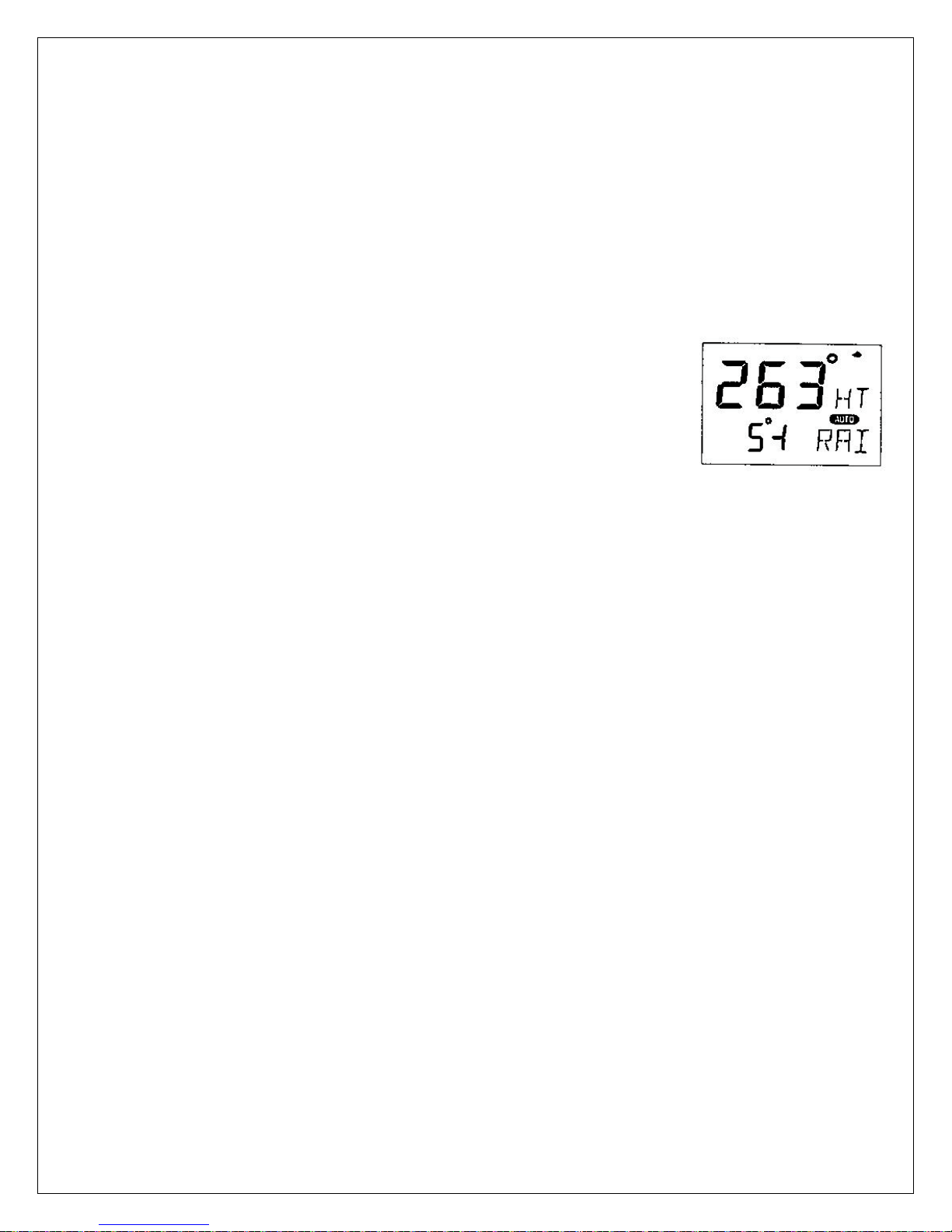
To select power steering, press MODE until the page-arrow
appears under PWR ST, and Rudder Angle Indicator[RAI] is
flashing on the lower-line. Your present course is displayed on
the top-line.
To activate power steering, press SET when [RAI] is flashing.
The rudder angle, followed by a sign for port or starboard is
displayed on the lower-line.
To change the rudder angle to starboard press RIGHT and hold it,
until the desired rudder angle is displayed.
To change the rudder angle to port press LEFT and hold it, until
the desired rudder angle is displayed.
5.2.7 Dodging and Returning to last Automatic Steering Function
To dodge, turn off the automatic steering by pressing OFF and
dodge manually.
If you want to re-activate the last steering function and value, press
MODE and SET together, within 10 minutes after turning off the
automatic steering.
This function is not available after 10 minutes after Autopilot off, or
if the Autopilot has been turned off by pressing OFF for more than
two seconds.
Page 40

ComNav 1500 / 1510 Autopilot - 33 -
6. SETUP
6.1 Setup Mode
To get the most out of your 1500 or 1510 Autopilot, it is important to carefully setup
and calibrate your Network. The settings are stored in a non-volatile memory, which
means they will remain in memory after you have turned off the power. To get an
overview of your Network settings, we recommend that you note your settings.
6.1.1 Setup Mode Divided into 4 Setup Groups
[Lit OFF] = Lighting setup group
[P0] - [P9] = Pilot setup group
[A0] - [A4] = Alarm setup group
[C0] - [C6] = Compass setup group
6.1.2 Access Setup Mode
To access setup mode, press and hold MODE more than 2
seconds.
To move to next setup group, press MODE.
To scroll up and down in each group press LEFT or RIGHT.
6.1.3 Change a Setting
To unlock a setting, press SET.
To change a setting, press LEFT, RIGHT and MODE as required.
To lock a setting, press SET.
6.1.4 Return to Previous Mode
To return to previous mode, press SET when the text return [RET]
is displayed.
6.1.5 Factory Default Settings
After each setting we have listed the factory default settings. This allows you to
manually get back to factory default settings, if needed. There is no automatic way
to get back to factory default settings, it has to be done manually.
All Autopilot instrument settings are central, and affect all connected Autopilot
instruments and their commands.
Note! The APC routine automatically sets these settings:
[RUD], [SEA], [CRD], [ATC] and [RRS].
Therefore these settings and their minimum and maximum values
and times, depend on how your boat behaves.
Page 41
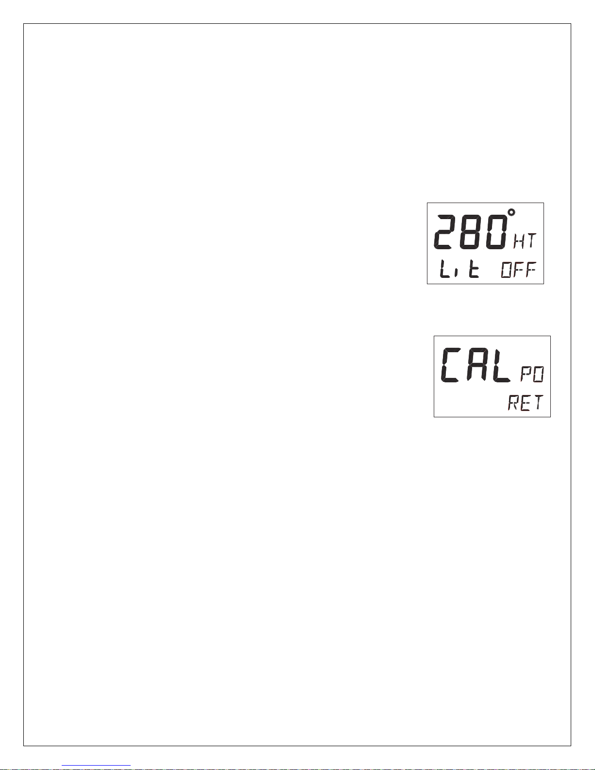
ComNav 1500 / 1510 Autopilot - 34 -
Caution! All setup routines can be adjusted while the boat is
underway with Autopilot functions activated. Always be in a
position to monitor the boat’s heading and to watch for navigational
hazards when calibrating the Autopilot. Be prepared to turn off the
Autopilot by a long press on OFF, to revert to manual steering
immediately if an undesired heading occurs. If navigating with an
automatic steering function in a hazardous situation, do not adjust
setup routines while underway.
6.2 Lighting Setup Group [Lit]
The instrument uses red back lighting for the display and the 4
push-buttons. The light can be set at 4 different levels of
brightness.
To select between the 4 light levels [LOW], [MID], [MAX] and
[OFF], press RIGHT. To lock the selected level, press SET.
The selected light level will be copied to all NX2 instruments
connected to the Network. It is not possible to select the lighting
level individually for single instruments.
6.3 Autopilot Setup Group [P]
6.3.1 P0, Return [RET]
To return to previous mode, press SET when the text [RET] is
displayed.
6.3.2 P1, Rudder [RUD]
Possible settings are [0] = Minimum to [9] = Maximum.
Set by the APC routine.
The setting affects the degree of rudder angle used.
The most critical adjustment for good steering is the rudder. Too
high of a setting will cause excessive amounts of rudder movement,
which forces the boat to hunt rapidly back and forth across the
course. Too low of a setting lets the boat slowly fall off course, with
repeated corrections required to get back on course.
The rudder should be set to the position where positive control of
the steered course desired, is achieved without undue activity. Run
the boat at its cruising speed and make a course change of 40°,
with the push buttons. The boat should not overshoot by more than
approximately 5°. Adjust the rudder until this is achieved.
Page 42
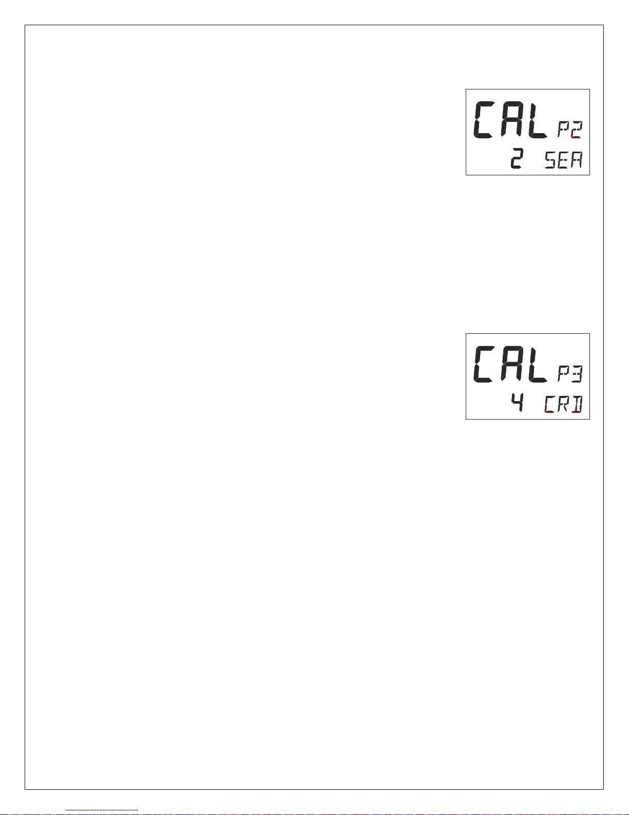
ComNav 1500 / 1510 Autopilot - 35 -
6.3.3 P2, Damping of compass heading [SEA]
Possible settings are [0] = Minimum to [9] = Maximum.
Set by the APC routine.
This setting is a combination of yaw dead-band (compass
sensitivity) and compass damping. The minimum setting may
only be used under calm sea conditions to avoid unnecessary
rudder correction due to compass acceleration errors.
Smaller boats and high speed boats, which are subject to more
acceleration in lighter seas will have to use higher settings. Larger
and more stable boats can use lower settings since there is less
compass disturbance. Default setting should work on most boats
in light to moderate sea conditions. Following seas, no matter how
rough, require lower settings to catch course error trends
quickly in order to minimize excessive yaw.
6.3.4 P3, Counter Rudder [CRD]
Possible settings are [0] = Minimum to [9] = Maximum.
Set by the APC routine.
This setting senses the rate of change of heading and gives
additional rudder corrections if the boat is rapidly falling off course,
and backs off the rudder as a boat approaches the desired
heading. Its effect is to rapidly catch the tendency to yaw in a
quartering sea, provide initially high rudder control when making a
large course change and to decelerate the swing of the bow, as a
boat approaches the desired course.
Course holding with heavy and difficult to steer boats is greatly
improved when using this feature. Insufficient counter rudder will
allow the boat to overshoot on large course changes. Too much
will cause unnecessary rudder corrections and a tendency to stop
short of coming to a new course, requiring several successive
corrections before easing up to the new heading.
To optimize counter rudder, initially set it to minimum and adjust
the rudder (see, [RUD] 5.3.2). Increment the counter rudder one
step at a time, while testing 40° course changes, until the
boat achieves an overshoot of 1° to 2° or less.
Remember, that any air in the hydraulic system will prevent
precision control.
Page 43
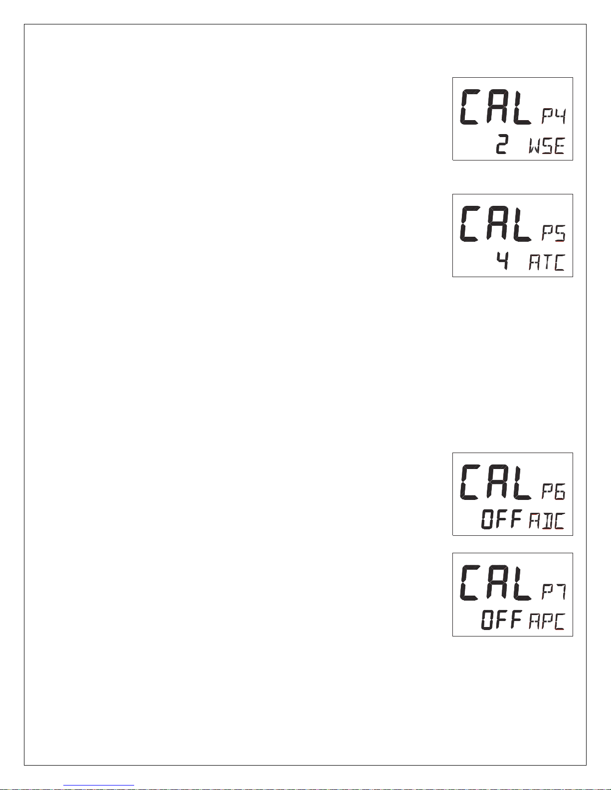
ComNav 1500 / 1510 Autopilot - 36 -
6.3.5 P4, Damping of wind [WSE]
Possible settings are [0] = Minimum to [9] = Maximum.
Default setting is [2].
Damping of wind transducer. The factory default setting
should be adequate. In very heavy weather or unstable
wind conditions, unnecessary corrections may be minimized
by increasing the setting.
6.3.6 P5 Automatic Trim Calibration [ATC]
Possible settings are [0] = Minimum to [9] = Maximum.
Set by the APC routine.
[ATC] is not critical. It constantly compares the course set against
the course steered and slowly applies more rudder as necessary to
reduce any errors to zero. Errors may be due to wind, waves or
other unbalanced forces such as single screw operation of a twin
screw boat, an off-center tow or weather helm on a sailing boat,
etc. If the trim time is set too high, it will take a long time to
eliminate the course error. If it is set too low it can start to degrade
course stability.
In general, longer trim times (higher settings) should be set for
large boats and sailing boats and shorter trim times (lower
settings) for small boats and high speed planning boats. The
factory default setting should be acceptable for all but extreme
applications.
6.3.7 P6, Adaptive Control [ADC]
Possible settings are [OFF] or [On].
This function is reserved for future functions.
6.3.8 P7, Automatic Pilot Calibration [APC]
Possible settings are [ON] or [OFF].
The APC routine automatically sets: [RUD], [SEA], [CRD], [ATC]
and [RRS].
The Autopilot will not function unless the boat pass the APC
routine. The APC will automatically determine and correct how
wires and pipes are connected. It will also learn how the boat
reacts on different rudder commands and automatically calibrate
itself.
To learn how to perform the APC function, see Sea Trials.
Page 44

ComNav 1500 / 1510 Autopilot - 37 -
6.3.9 P8, Rudder Reduction Speed [RRS]
Possible settings are [0] = Minimum to [9] = Maximum.
Set by the APC routine.
The [RRS] controls the flow of the Pumpset. It will effect the
Pumpset, but not a solenoid valve steering system.
The [RRS] will be set to [5] after the APC routine is performed.
It is then possible to increase or decrease the speed reduction
of the Pumpset motor.
6.3.10 P9, Rudder angle limit [LIM]
Possible settings are [00°-99°]. Default setting is [00°].
An angle of 00° is the same as rudder angle limit disconnected
(OFF).
Note! Make sure [LIM] is set to 00° (OFF) during installation.
The rudder angle limit sets maximum angle for the rudder. If the
limit is set to 45°, it is not possible to exceed a rudder angle 45° on
either port or starboard. Check the maximum rudder angle by
turning the steering wheel to port and starboard and read the
maximum angle. If the angle is greater on one side, decrease the
smallest angle by 3°, and enter that setting as the limit.
Page 45
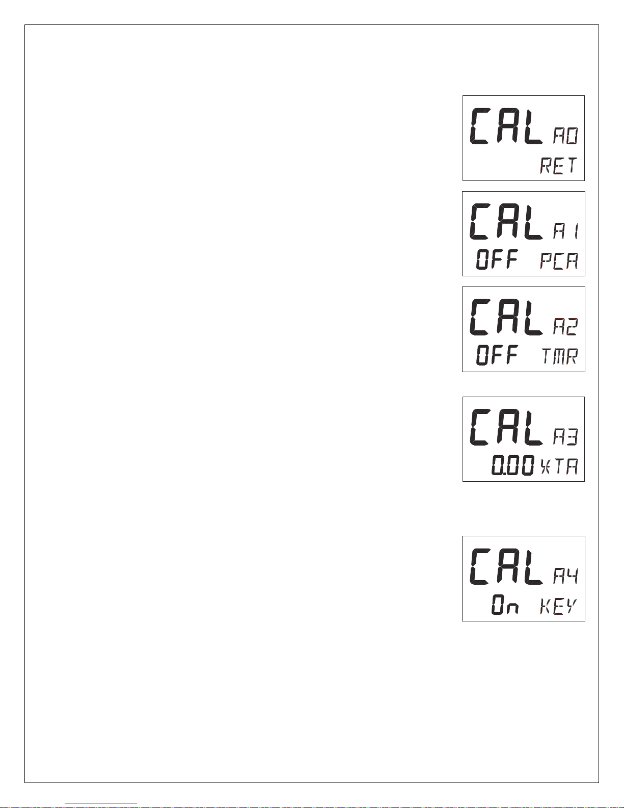
ComNav 1500 / 1510 Autopilot - 38 -
6.4 Alarm Setup Group [A]
To silence an alarm, press any push button.
6.4.1 A0, Return [RET]
To return to previous mode, press SET when the text [RET] is
displayed.
6.4.2 A1, Pilot Course Alarm [PCA]
Possible settings are [OFF] and [00°-99°]. Default setting is [OFF].
When the boat’s average course differs more than the [PCA]
setting, the alarm will sound and the display will blink.
6.4.3 A2, Timer Watch Alarm [TMR]
Possible settings are [OFF] or [On]. Default setting is [OFF].
On = audible alarm activated.
The audible alarm will sound every 5 minutes to alert the person on
watch to confirm and restart the timer, press any push-button. If not
confirmed within 1 minute, the optional external alarm buzzer, if
connected to the NX2 Server, will sound for 1 minute, to alert the
rest of the crew.
6.4.4 A3, Cross Track Error Alarm [XTA]
Possible settings are [0.00] = OFF to [9.99]. Default setting is
[0.00].
This function is only available in NAV function when the Autopilot is
connected to a NX2 Network and a navigator is connected to the
NX2 Server.
If the pilot’s cross track error exceeds the set threshold of distance
of the track, the alarm will be activated.
6.4.5 A4, Push-Button Beep [KEY]
Possible settings are [OFF] or [On]. Default setting is [ON].
[On] = Sound when push buttons are pressed. [OFF] = No sound.
Page 46
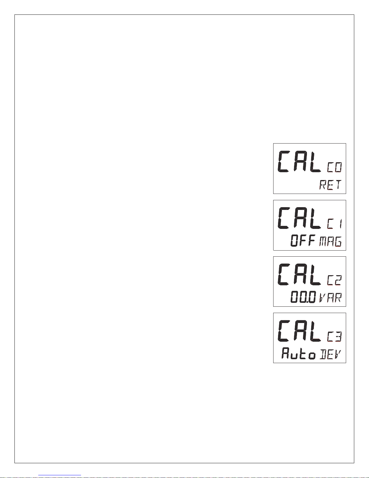
ComNav 1500 / 1510 Autopilot - 39 -
6.5 Compass Setup Group [C]
Auto-deviation, auto-deviation-check and auto-deviation clear, are
only available if a NX2 compass transducer is connected. The
auto-deviation routine will automatically correct all possible faults,
except alignment.
Note! As soon as you place any kind of ferrous items close to the
compass, the auto-deviation and auto-deviation check routines
should be repeated. So if you have packed your boat for the
vacation, think about where you place ferrous items in relation to
the compass transducer.
6.5.1 C0, Return [RET]
To return to previous mode, press SET when the text [RET] is
displayed.
6.5.2 C1, Magnetic Heading [MAG]
Possible settings are [OFF] and [On]. Default setting is [OFF].
[On] = All headings will be magnetic.
[OFF] = All headings will be true, i.e. corrected for local variation
set in C2, Local variation [VAR]. This is local setting.
6.5.3 C2, Local Magnetic Variation [VAR]
Possible settings are [+/-00.0°-99.9°]. Default setting is [00.0]
Easterly variation = underlining ( _ ) sign.
Westerly variation = minus ( - ) sign.
The local magnetic variation is usually printed in the sea chart.
6.5.4 C3, Auto-Deviation [Auto DEV]
This function is used to automatically correct the deviation of your
compass.
Take the boat into a slow turn, in calm sea and away from other
boats or obstructions. There is no need to perform a perfect circle.
When steady, select C3 [Auto DEV] and press SET to start. The
present "uncorrected" compass heading is displayed and the
compass auto-deviation is in progress. Turn the boat in a 1 ¼
circle, and when ready press SET again.
If successful, the text [CAL C3] [Auto DEV] will be displayed.
Page 47
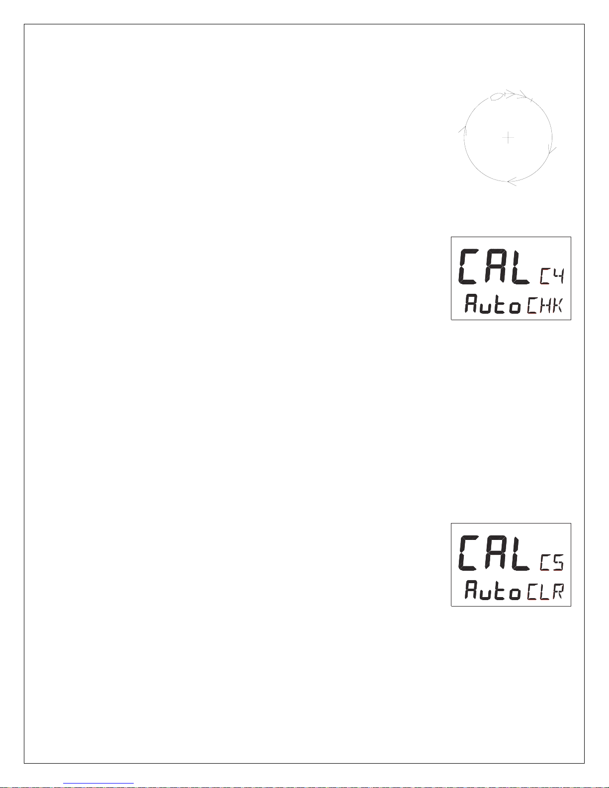
ComNav 1500 / 1510 Autopilot - 40 -
If not successful, an error messages can be displayed:
• [Err 15]: Make sure an Autopilot function is not activated and
carry out the auto-deviation procedure aga
in.
• [Err 16]: Auto-Deviation is not possible, because a NMEA
compass is selected
as compass for the NX2 Network.
• [Err 17]: The 1 ¼ turn was not performed or the compass is
affected by strong magnetic distortion.
You may interrupt the auto-deviation procedure at any time by
pressing LEFT and RIGHT together.
To check the auto-deviation, carry out the auto-deviation check
routine.
6.5.5 C4, Check Auto-Deviation [Auto CHK]
This function is used to check your auto-deviation.
The result of [Auto CHK] will be compared with [Auto DEV]. If the
deviation is less than 1.5°, the average value from the comparison
between [Auto DEV] and [Auto CHK] will be stored.
MIN 400°
Take the boat into a slow turn, in calm sea and away from other
boats or obstructions. There is no need to perform a perfect circle.
When steady, select C4 [Auto CHK] and press SET to start.
The present compass heading is displayed and the compass
Autodeviation check is in progress. Turn the boat in a 1 ¼ circle.
To end the routine, press SET again.
If successful, the text [CAL C4] [Auto CHK] will be displayed.
If not, [ERR 17] or [ERR 19] will appear, i.e. the difference between
the last auto-deviation and this autodeviation check was too great
to be accepted.
Make a new auto-deviation-check, and if you still get [ERR 19],
make a new auto-deviation, since the last one was probably
disturbed.
6.5.6 C5, Clear Auto-Deviation [Auto CLR]
To clear the calibration created by the auto-deviation, select C5
[Auto CLR], and press SET.
Page 48

ComNav 1500 / 1510 Autopilot - 41 -
6.5.7 C6, Adjust Compass Alignment [ADJ]
Possible settings are [000°] to [359°]. Default setting is [000].
Compass transducer alignment correction or the so called,
”A-fault”.
Allows 180° reversed mounting if needed. Never mount the
transducer at right angles to the boats fore-aft line.
Make sure that the local magnetic variation is entered before
you make the alignment adjustment, otherwise you are unable
to see the difference between local magnetic variation and
alignment error.
To check the transducer position, sail/steer your boat in a straight
line towards two visible objects in a line. If the actual heading taken
from the sea chart is 330° and the compass displays 335°, then set
the value of 360° - 5° to 355°.
Page 49
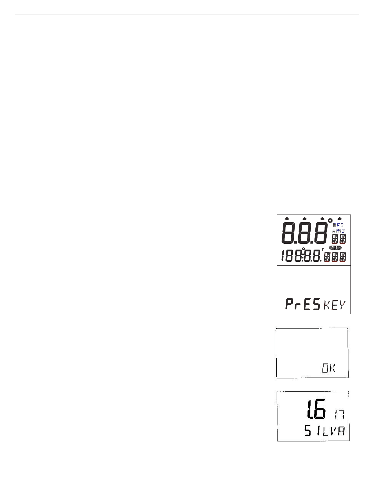
ComNav 1500 / 1510 Autopilot - 42 -
7. DOCKSIDE TESTING
7.1 Preparations
Start checking the following:
• Familiarize yourself with the operating procedures by reading
sections Operation, Function and Setup.
• Double check all wiring connections and DIP Switch settings
prior to connecting power to the system.
• Make sure rudder angle limit [LIM] is set to 99° (OFF).
• Ensure that the oil reservoir is 3/4 full and maintain that level
throughout the test procedure.
Warning! Do not activate any of the 3 Autopilot functions
Compass, Nav or Wind at dock as the rudder may go hard over,
since the APC routine has not been carried out yet. It will be done
as explained in Sea Trials.
7.2 Dockside First Start Up
7.2.1 Power On
At each power on, the instrument will perform a self test. The
display will first show all segments, then the software version and
the NX2 Network ID number.
7.2.2 Initializing the Instrument in a NX2 Network
At the first power on after installation, you will be asked to press
SET [PrSKEY]. This will give the instrument a logical ID number
from 16 and upwards on the NX2 Network.
To initialize the instrument, press SET, one instrument at a time,
on all installed digital instruments,.
Warning! Always wait for the text [Init OK]
to be displayed, before you press SET
on the next instrument!
The NX2 Distribution Unit or the Server automatically gives the
first unit ID number 16, then 17 and so on. The order in which
you press SET, will be the same order as the instruments will be
given a logical ID number on the NX2 Network, and the same
order they will be addressed by the Remote Control instrument
if used.
The example shows that the instrument version number is
1.6 and the logical ID number given is 17.
Page 50

ComNav 1500 / 1510 Autopilot - 43 -
Warning! Do not activate any Autopilot functions until Dockside
Testing and Sea Trials APC routine have been performed.
7.2.3 Re-Initializing the Instrument
If two instruments have been given the same ID number by
mistake, you must re-initialize the instruments to avoid Network
disturbance and blockage of data.
To re-initialize the instrument, be prepared to press Left and Right
together during the short power up sequence, i.e. when version
and ID numbers are displayed.
The display test is then re-started on all instruments and you will
be asked to press SET on one instrument at the time as explained above.
Note! If you do not succeed to re-initialize, we suggest you
disconnect (just pull out the connection plug) on all, except one of
the instruments that had the same ID number, then re-install the
instruments and repeat the above procedure.
Run the procedure as described in Dockside First Start Up.
7.3 Remove Air from System
Filling the hydraulic system (for reversing Pumpsets and liner drives only).
Select PWR ST function by pressing MODE until the page-arrow appears under
PWR ST.
To activate the Autopilot, press SET.
Press and hold LEFT or RIGHT until the Pumpset begin to run and the rudder
moves.
If port rudder is given when you press starboard (RIGHT) push-button, and vice
versa, ignore the reversal. It will be corrected automatically when doing the APC
routine at Sea Trials.
It may take time before the steering begins to move due to air in the system.
Continue to press and hold the push-button until the steering reaches its stops.
Then reverse direction with the opposite push-button. Repeat this procedure 10
times or more until the system appears to move smoothly.
After 5 or 10 minutes of this purging, let the system rest so that entrained air can
settle out of the oil. After 5 minutes of rest, repeat the above procedure.
(With linear drives the wheel cannot be turned to assist purging unless the bypass
valve is temporarily disconnected. Make sure that the valve wiring is reconnected
before further testing. Also, with linear drives, when attempting to get air out of the
system make sure the flow adjusting wheel is set at a mid flow position).
Page 51

ComNav 1500 / 1510 Autopilot - 44 -
Air in the system may cause noisy Pumpset operation. When the Pumpset
becomes quieter and the steering moves smoothly and the linear drive responds
instantly in both directions, it may be assumed that most air is out of the system.
To check that all air is removed, select power steer function and try to turn the
steering wheel. In this function the steering wheel should be stiff. If you can turn the
wheel a certain amount with a increasing pressure as a result, there is still air in the
system.
Continue to ventilate the system until the steering wheel is stiff before you proceed
with the sea trials.
Do not attempt to activate the Autopilot in other functions than power steer, until all
air is out of the system. Sloppy course holding will result if you do. The very last air
removal will be done as the boat is tested underway.
7.4 Adjust the Pumpset Flow Rate
The Autopilot is capable of automatically adjusting the flow rate of the Pumpset. If
using a fixed flow rate Pumpset there is no adjustment of the flow rate required.
However, if using a variable flow rate Pumpset, adjust the flow rate of the Pumpset
for approximately 14 seconds hardover to hardover time or slower for best steering
accuracy.
7.5 Functional Tests
Read Operation, Function and Set Up of the manual to familiarize yourself with the
operating procedures. Try the different modes at the dock to verify that all systems
are working and ready for sea trials.
Do not try to make course changes in pilot modes as the rudder may go hardover,
since the [APC] Pilot Calibration has not been conducted yet.
When you finished the Dockside Testing, perform the Sea Trials.
Page 52

ComNav 1500 / 1510 Autopilot - 45 -
8. SEA TRIALS
8.1 Preparations
Take your boat out at half speed to calm seas away from other boats or
obstructions to run the sea trials. Then proceed as per below.
Warning! Do not activate any of the Autopilot functions (Compass, Nav or Wind) at
dockside as the rudder may go hard over, since the APC routine has not been
carried out yet.
8.2 Compass Calibration
Enter the compass calibration.
Note! If you are using an existing NX2 Compass transducer that already has been
compensated, it is not necessary to run the auto-deviation [Auto DEV] procedure
again.
Local Magnetic Variation:
Run the calibration routine local variation [VAR].
Automatic Compass Compensation:
Run the calibration procedure auto-deviation [Auto DEV].
Automatic Compass Check
Run the calibration procedure auto-deviation-check [Auto CHK].
Misalignment Correction
Run the calibration procedure compass alignment [ADJ].
8.3 Automatic Pilot Calibration [APC]
The Autopilot will not function unless the boat pass the APC routine. The APC will
automatically determine and correct how wires and pipes are connected. It will also
learn how the boat reacts on different rudder commands and automatically calibrate
itself.
The APC routine automatically sets: [RUD], [SEA], [CRD], [ATC] and [RRS].
Select P7 [APC]. To unlock, press SET. To change to [On], press LEFT or RIGHT.
To activate the APC, press SET.
All 4 page arrows at top of display will now be lit to confirm the APC procedure is in
action.
The boat should automatically turn slightly to port and starboard and return to
original course.
Page 53

ComNav 1500 / 1510 Autopilot - 46 -
If the APC fails: Error message 34 (calibration failure) is displayed. This is most
likely caused by too much air still in the system. To escape the error message,
press any push-button. Revert to 10.3. ”How to remove air from the system”. Note!
You can ”help” the APC process by manually pulling the steering wheel or tiller in
same direction as APC turns the boat to pass the APC.
If the APC is successful: All 4 page-arrows disappear, the instrument leaves the
setup mode and returns to standby mode automatically.
Note! You may interrupt the APC routine at any time by a press on SET.
Congratulations, your Autopilot calibration is done.
Now go ahead and activate the Autopilot and enjoy the NX2 performance.
Page 54

ComNav 1500 / 1510 Autopilot - 47 -
9. FINE TUNING
The factory default settings and the APC routine will provide acceptable
performance for most boats, but each boat has different steering characteristics
and some fine tuning may be necessary for optimum performance.
For individual settings referred to below, see the setup section.
The tests should be performed under fairly calm sea conditions with minimal wind
or tide. If wind and/or tide are unavoidable set a course for minimum effects from
these causes. It is recommended that these sea trials not be done in restricted or
busy waters.
Step by Step Instructions How to Fine Tune the Autopilot:
1.
Check that Dockside Testing, Sea Trials including the APC routine has been
done. If not, go back and make sure they are done.
2.
Activate the Autopilot on a course and ensure that it holds without excessive
understeering or oversteering.
3.
With the boat travelling in a straight line at its normal cruising speed in calm
water, activate the Autopilot compass function. Make a 40° course change
using the LEFT or RIGHT and the boat should not overshoot by more than 1° to
2°. Continue making 40° course changes while adjusting the Rudder [RUD]
setting until the boat overshoots the correct course a few times prior to setting
on the course. This is the optimal [RUD] setting that can be used on the boat at
the current cruising speed and load, in calm waters.
4.
Continue making 40°course changes while slowly increasing the Counter
Rudder [CRD] setting, until the boat settles onto course with only one overshoot
of 3° or less. On some boats, the [RUD] setting may have to be decreased by
one position to get the boat to control properly. The [RUD] and [CRD] settings
are set to the maximum combined settings that should be used on the boat at
that speed and under the existing sea conditions.
The [RUD] and [CRD] settings may need to be increased in rough weather. The
higher the [CRD] setting relative to the [RUD] setting for calm weather, the less
it will need to be increased in rough weather. As the boat's speed decreases,
the rudder becomes less effective.
The [RUD] and [CRD] settings may need to be increased as the speed
decreases. The higher the [CRD] setting relative to the [RUD] setting, the less it
will need to be increased at lower speeds.
Page 55

ComNav 1500 / 1510 Autopilot - 48 -
To find the optimal [RUD] and [CRD] settings at different boat speeds, or when
the boat is towing, follow the procedures outlined in #3 and #4 above. Make a
record of the different settings needed to control the boat at all typical speeds,
loads and weather conditions normally experienced. Due to the wide dynamic
control range and self-tuning features of the microprocessor control, settings
determined for cruising speed in calm seas may be found acceptable without
further change at slower speeds and in heavier seas.
The compass damping [SEA] setting is a combination of yaw dead-band
5.
(compass sensitivity) and compass damping. The minimum setting may only be
used under calm sea conditions to avoid unnecessary rudder correction due to
compass acceleration errors.
Smaller boats and high-speed boats, which are subject to acceleration in even
lighter seas, will have to use higher settings.
Larger and more stable boats can use lower settings since there is less
compass disturbance. Factory default setting should work on most boats in light
to moderate sea conditions.
Following seas may require lower settings to catch course error trends quickly
in order to minimize excessive yaw and steering activity.
6.
Automatic Trim Calibration [ATC] adjustment is not critical. It constantly
compares the course set against the course steered. The automatic trim slowly
applies more rudder as necessary to reduce any persistent errors to zero. Such
errors may exist due to wind, waves or other unbalanced forces such as single
screw operation of a twin screw boat, or an off-center tow or weather helm on a
sailing boat. If the trim time is set too high, it will take a long time to eliminate
the course error. If it is set too low it can start to degrade course stability.
In general, longer trim times (higher settings) should be set for large boats and
sailing boats and shorter trim times (lower settings) for small boats and high
speed planning boats. The factory default setting should be acceptable for all
but extreme applications. If after fine tuning all routines and auto-deviation
routine has been done and poor steering is noted only on some but not all
headings, magnetic interference is present which must either be compensated
for by a compass adjuster and/or another compass location must be found.
Page 56

ComNav 1500 / 1510 Autopilot - 49 -
9.1 Optional Fine Tuning for Special Applications
Potentiometer adjustments, functionality on Distribution Unit.
VR1: Anti-hunt control for rudder: Inappropriate adjustment could result in steering
oscillations or degradation of steering performance. The potentiometer is factory
set at minimum deadband setting. Adjustment of this potentiometer can be used to
adjust deadband for rudder response, compensating for slack in steering system,
and/or lack of stiffness in cylinder support.
VR2: Analog External Rudder Angle Indicator Instrument deflection adjustment (if
applicable).
VR3: Analog External Rudder Angle Indicator Instrument offset adjustment (if
applicable).
VR4: Factory set; counter rudder delay primarily used on large vessels (over 100’ in
length).
VR5: Control head digital display Rudder Angle Indicator offset adjustment;
potentiometer is factory set; to be minor adjusted by Autopilot technicians if rudder
transmitter linkage can not be adjusted; inappropriate large adjustments could
result in poor Autopilot performance; do not adjust when in full follow up steering
mode. This is not available on 1510 Distribution Unit.
VR6: Current limit adjustment for servo drive; potentiometer is factory set; do not
adjust.
Page 57

ComNav 1500 / 1510 Autopilot - 50 -
10. PROBLEM SOLVING
10.1 General
Before you contact your ComNav dealer, and for them to give you better
service, please check the following points and make a list of:
• All connected instrument and transducers, including their software versions.
• NX2 Network ID numbers for each instrument (displayed at power up).
In most cases, the reason for faults in electronic equipment is poor installation.
Therefore, always first check for the following:
• Installation and connections are made per instructions for instruments and
transducers.
• Screw terminals are carefully tightened.
• There is no corrosion on any connection points.
• No loose ends in the wires, causing short cuts to adjacent wires.
• Cables for damage and that none are squeezed or worn.
• Battery voltage is sufficient, should be at least 11 V DC.
• The fuse is not blown and that the circuit-breaker has not opened.
• The fuse is of the right type.
• Two instruments do not have the same ID number.
10.2 Symptom - Cause - Action
In the table below, causes marked [ * ] are more likely to occur during installation or
when rewiring has taken place.
SYMPTOM CAUSE ACTION
Autopilot does not turn off. * Voltage below minimum. Make sure 12/24 volts is applied to
battery terminals in Distribution Unit.
Autopilot does not turn on.
Autopilot turns on, but the
Pumpset doesn’t run
* Voltage not applied. Make sure 12/24 volts is applied to
battery terminals in Distribution Unit.
* Voltage polarity is reversed. Make sure + and – is applied to
correct terminals.
* Boats safety switch is open. Close the safety switch.
* Fuse b
Slow blow (high current) fuse in
Distribution Unit is blown.
Rudder speed set too low. Decrease RRS setting.
urned out. Check and replace fuse as
necessary, located in the Distribution
Unit.
Replace fuse. If fuse regularly blows,
check for excessive rudder load or
mechanical defects in steering
system.
Page 58
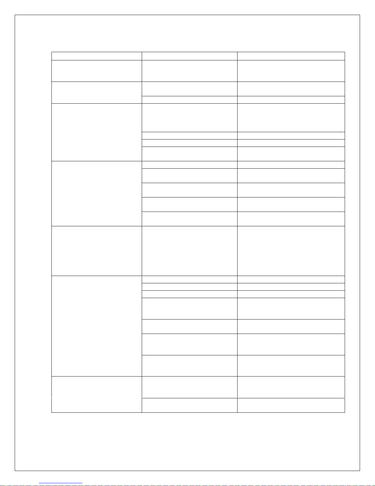
SYMPTOM CAUSE ACTION
Motor Pumpset turns but the
rudder doesn’t move.
Blinking [Low Bat] on bottom
line of display.
When Autopilot engaged,
rudder goes hardover.
Autopilot wanders on some
headings.
Autopilot wanders on all
headings.
Rudder movement erratic.
ComNav 1500 / 1510 Autopilot - 51 -
Pumpset drive section in
Distribution Unit may have failed
to open.
Broken or loose motor coupling Replace or tighten coupling as
Pumpset contamination. Clean or replace Pumpset.
Low battery voltage. Automatic
shut-off in case of voltage lower
than 10.5V for 12V battery and
21.5V for 24V battery.
Poor wiring connection. Check for voltage drop and repair.
Power wiring is undersized. Replace wiring with correct gauge.
Voltage drop across circuit
breaker.
APC routine not performed. Pilot calibration “APC” required.
Power transistors in Distribution
Unit may be shorted.
Rudder Transmitter linkage
disconnected.
Rudder Transmitter wiring
shorted or open circuit.
Rudder Transmitter pot
defective.
Magnetic interference is present.
The worst steering is usually on
northerly headings in the
northern hemisphere and
southerly headings in the
southern hemisphere.
Severe magnetic interference. Choose another compass location.
Air in hydraulics. Fill and purge the steering system.
Slack in the steering system. Repair any loose or worn parts.
Rudder Transmitter
potentiometer is “noisy” or
intermittent.
Compass damaged; intermittent
wiring connections.
Slow wander means rudder
control is set too low
(understeering).
Fast wander means rudder
control is set too high
(oversteering).
Excess rudder load. Reduce rudder friction, increase
Air in system. Check for leaks and bleed the
Replace transistors, integrated
circuits or entire circuit board.
necessary.
Turn Autopilot off and charge
batteries or correct voltage loss.
When proper voltage restored,
restart Autopilot.
Make sure 25Amp circuit breaker is
used.
Replace transistors or entire circuit
board.
Re-connect and align as per
Installation Instructions.
Check and repair wiring as
necessary.
Replace.
Perform Auto-Deviation-Clear [CLR]
and Auto-Deviation [DEV] again, or
try another compass location.
Investigate for magnetic
disturbances around compass, e.g.
Masses of steel, motors,
loudspeakers, etc.
Replace rudder potentiometer.
Repair any loose or worn parts;
recheck and connect wiring.
Increase Autopilot setting [P1] [RUD]
Decrease Autopilot setting [P1]
[RUD]
steering cylinder size, increase
power of the Pumpset.
system.
Page 59
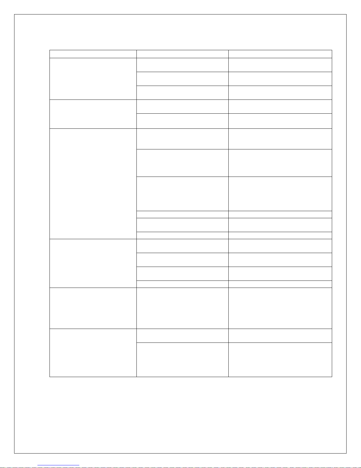
SYMPTOM CAUSE ACTION
Rudder Angle Indicator is
displaying erratic values.
Boat overshoots on large
course changes.
Course set on Autopilot
instrument is different from
ship’s steering compass.
NMEA does not engage, NAV
arrow does not come on.
After some use, NAV arrow
does not come on.
Course under NAV steering is
erratic.
ComNav 1500 / 1510 Autopilot - 52 -
Rudder Transmitter is defective
(noisy).
Check for loose or broken wires
in terminal strips.
Check for broken wires in
cables.
Rudder control set too high. Decrease Autopilot setting [P1]
Counter rudder set too low. Increase Autopilot setting [P3]
If constant error, Autopilot
compass is not aligned with
foraft line of boat.
Variable error in heading caused
by magnetic interference.
Larger errors not corrected by
above remedies or lack of
change in course set point with
different headings indicate a
defective compass.
Ships compass is not correct. Compensate ships compass.
Compass: no reading or wrong
heading.
Irregular values. Check the Sea Damping [P2] [SEA]
NMEA receiver not installed
correctly.
No NMEA 0183 data received. Check Nav cable for connection to
Unreliable NMEA data detected
upon engagement.
No active waypoint. Activate a waypoint.
Poor NMEA data detected. Last
“good” NMEA heading is used
until good data restored.
May appear when close to
waypoint due to GPS-S/A error.
Compass heading information is
not consistent with navigator.
Replace Rudder Transmitter or
potentiometer within.
Reconnect tightly.
If wiggling of cable where it flexes
causes rudder activity, replace cable.
[RUD]
[CRD]
Use compass setting [C6] [ADJ] to
adjust alignment of compass.
Verify that the steering compass is
accurately corrected and then
correct the Autopilot compass as per
installation instructions.
1. Run Auto-Deviation-Clr [C5]
[CLR]
Run Auto-Deviation [C3] [DEV]
2.
3. Recheck compass again.
Check that the local magnetic
variation [C2] [VAR] is set properly.
Check receiver settings for proper
output.
the correct port.
Check connections and setup in
transmitting instrument.
Check for poor navigator installation
causing bad signal to noise ration.
Check for erroneous data as
detected by navigator. Revert to
magnetic course only, if situation can
not be corrected.
Accept situation, or revert to
compass course steering only.
Set heading type in Autopilot to
match output from Navigator. (i.e.,set
to true if Navigat outputs true. Set to
magnetic if Navigator outputs
magnetic).
Page 60

ComNav 1500 / 1510 Autopilot - 53 -
10.3 NX2 Network Error Messages with Cause and Remedy
If an error message [Err #] is displayed, an error has been detected by the NX2
Network. The message can assist you to diagnose the cause and remedy the error.
To escape from an error message, press any push-button. If not possible to
escape, reset power (turn off and on again), then remedy the situation as
suggested below.
Note! For errors marked with [*], contact your ComNav dealer or the factory in
order to return the unit for rectification.
NO. MESSAGE AND CAUSE REMEDY *
01 Activated watchdog timeout Reset power.
02 NX2 Network data frames are
missing.
03 No data received within approx. 10
sec.
04 EEPROM read. Reset power.
05 EEPROM write. Reset power.
06 RAM memory error. Reset power.
07 Auto-log full, in GPS Compass. Clear Auto-log memory.
08 Break reset. Reset power.
09 EEPROM auto initiation, or NMEA
transmit fail. (NX2 Server only).
10 Range error, input e.g. 17° 70’ = too
many minutes.
11 Remote control setup error.
Command can not be executed.
12 No response from Navigator Check navigator connection and
13 Waypoint not defined. Define a waypoint.
14 Impossible command when used
with an external NMEA navigator.
15 Impossible command when in
Autopilot mode.
16 Auto-deviation is not possible. Check for extreme magnetic field,
17 Auto-deviation check failed. 1-¼ turn not complete or extreme
18 Auto-deviation. Function denied. Function denied since compass is
Check connections and setup.
Check connections.
Reset power.
Correct input format.
Check connections and settings.
settings.
Use only possible command.
Use only possible commands.
upside down mounting of
transducer or wrong transducer
type.
magnetic disturbance.
busy with the Auto-deviation
routine.
*
*
*
*
*
*
Page 61
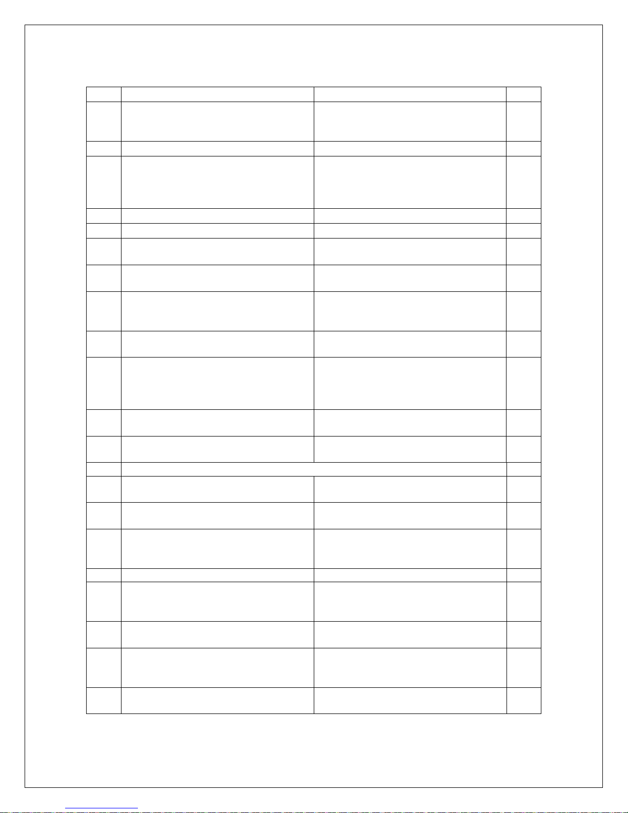
ComNav 1500 / 1510 Autopilot - 54 -
NO. MESSAGE AND CAUSE REMEDY *
19 Auto-deviation failure. Error larger than 1.5°. The boat
probably hit a wave during the turn.
Redo.
20 GPS to CPU communication error. Reset power.
21 GPS acquisition failure (time out). Maximum allowed time for
searching satellites. E.g. When try
to navigate indoors. Check GPS
antenna location.
22 CPU to GPS communication error. Reset power.
23 DGPS (RTCM) data ignored. Change the DGPS (RTCM) setting.
24 GPS bad fix, no fix position (time
expired at one-fix).
25 No Autopilot response.
Object is not connected.
26 The unit is not allowed to power up
Because there is too high input
voltage.
27 Extended object server busy or
error.
28 Route command error. The
waypoint
Bank memory is full.
Check GPS antenna location.
Check wiring connections and fuse.
Check input voltage.
Set one GPS Navigator instrument
to master.
Clear waypoint bank to make
space.
*
*
*
29 DGPS mode is interrupted. Check the DGPS receiver.
42 Bad transducer input / bad
Reset power.
measurement.
NX2 Autopilot Distribution Unit
30 General Autopilot failure Reset
Reset Power.
power.
31 Autopilot compass input failure in
Autopilot standalone connection.
32 Autopilot compass input failure in
Autopilot Nexus Network
connection.
Check compass connection at
Autopilot Distribution Unit.
Check compass connection at
NX2 Server or at the Compass
Data instrument.
33 Received wind data input failure. Check wind wire connection.
34 Autopilot calibration failure. Check for air in the system and redo
the APC routine again in calm
water.
35 Navigation data not available in
Autopilot stand alone connection.
36 Navigation data not available in
Autopilot Nexus Network
Check NMEA input connections and
settings in the navigator.
Check connections and navigator
settings.
connection.
37 Autopilot Network re-initialization. Check connections and wire gauge.
*
*
Page 62
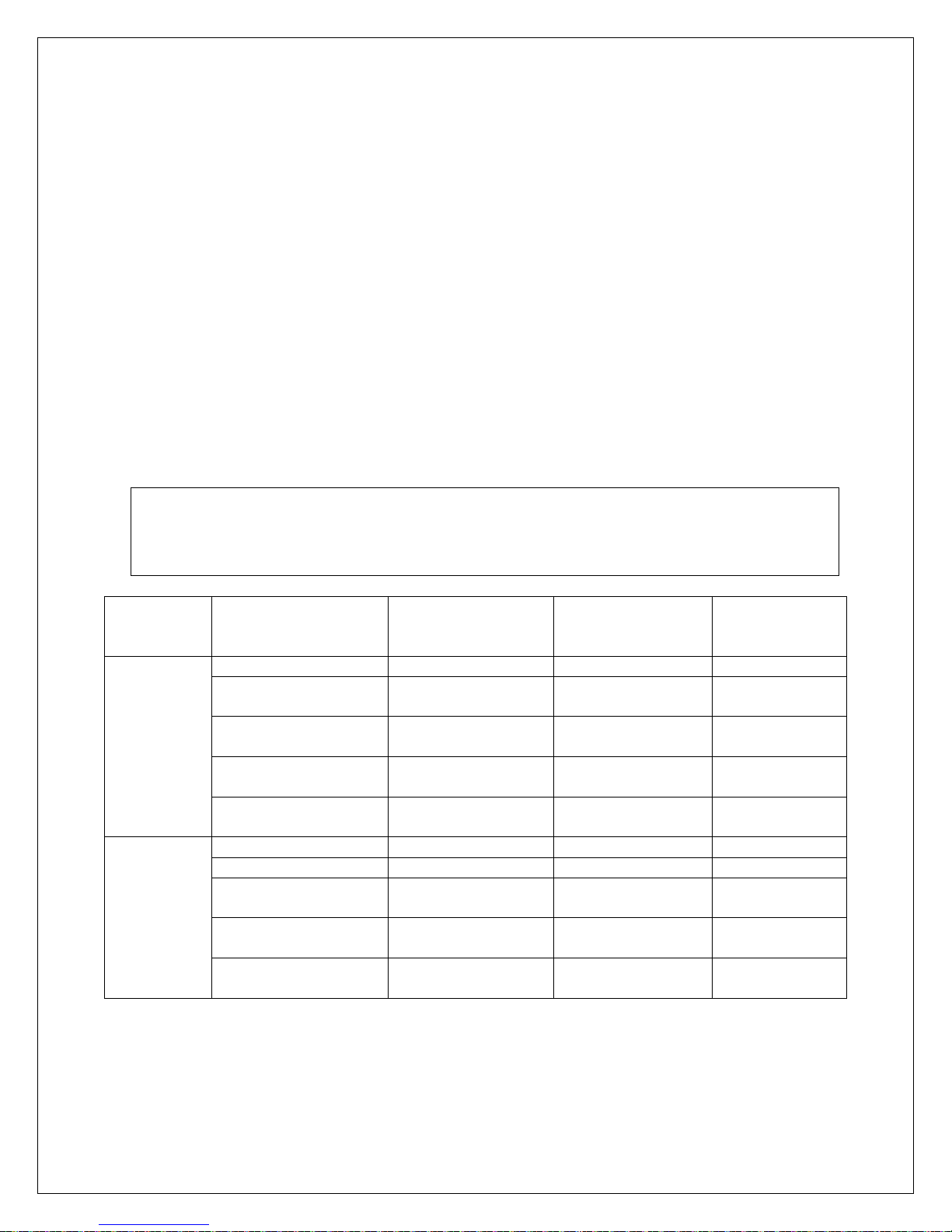
ComNav 1500 / 1510 Autopilot - 55 -
11. MAINTENANCE
11.1 Instrument Maintenance
• To clean the instrument, use only mild soap solution and rinse with water.
• Do not use detergents or high pressure washing equipment.
• At least once a year, check all your connections and apply additional silicon paste
at each connection point.
• When the instrument is not in use, always fit the instrument cover for protection
• Storing of instruments when not in use for longer periods: It is advisable to
remove the instruments and transducers and store them inside the boat or at
home preferably at room temperature.
11.2 Drive Unit Maintenance and Inspection Schedule
Perform the following inspections every three months or as per running hours listed
in the table below, whichever is less.
Warning!
Failure to rectify any faulty conditions discovered as a result of the inspection could cause
sudden loss of Autopilot control, with consequential danger. It is recommended that all
items referenced in the following table be inspected before commencing any cruise.
TYPE EQUIPMENT CHECKS REMEDY
Hydraulic
Mechanical
Oil reservoir level Correct Fill 200
Oil conditions Discoloration
Contamination
Hydraulic piping Damage
Leaks & Corrosion
Hydraulic fittings Damage
Leaks & Loosening
Piston rod seals on
Pumpset
Linear drive Corrosion Replace or Repair 2000
Tiller arm Corrosion Replace 2000
Tiller bolts Corrosion
Rod end bolt on
linear drive
Trunnion bolts
on linear drive
Leaking Replace 1000
Loosening
Corrosion
Loosening
Corrosion
Loosening
Flush system and
replace the oil
Replace 1000
Replace
Tighten
Replace
Tighten
Replace
Tighten
Replace
Tighten
INSPECTION
FREQUENCY
In Hours
1000
1000
500
2000
500
2000
500
2000
500
Page 63

ComNav 1500 / 1510 Autopilot
12. TECHNICAL SPECIFICATIONS
12.1 Autopilot Instrument
Dimensions: 113mm x 113mm x 23mm (4.3” x 4.3” x 0.9”)
Weight: 260g (9.17 oz)
Enclosure: Water proof
Instrument cable: 0.4 m (16”)
Power supply: 12 V DC (10-16 V). The instrument is polarity protected.
Power consumption: 0.08 W. At max lighting 0.8 W.
Current consumption: 7 mA (at 12V). At max lighting 70 mA (at 12V).
12.2 Distribution Unit A-1500
Dimensions: 220mm x 145mm x 55mm (8.7” x 5.7” x 2.2”)
Weight: 800g (28.2 oz)
Enclosure: Splash proof
Cable: 8m (26ft) NX2 cable
Power supply: 12 or 24 V DC (10-40 V)
Power consumption: 4 W, plus drive unit demand
Current consumption: 0.3A (at 12V)
Max. motor output drive: 25 Amps
Output: NMEA 0183 compass, RAI
- 56 -
12.3 Distribution Unit A-1510
Dimensions: 160mm x 110mm x 38mm (8.7” x 5.7” x 2.2”)
Weight: 420 g (14.8 oz)
Enclosure: Splash proof
Cable: 8m (26ft) NX2 cable
Power supply: 12 or 24 V DC (10-30 V)
Power consumption: 3 W, plus drive unit demand
Current consumption: 0.3A (at 12V)
Max. motor output drive: 15 Amps
Output: NMEA 0183 compass, RAI
12.4 Rudder Follower & Linkage
Dimensions:
Transmitter arm:
Ball joint linkage arm:
Weight:
Enclosure:
Cable:
Power supply:
Power consumption:
Current consumption:
Rudder angle:
Resistance:
Life:
51mm x 96.5mm x 89mm (3.0” x 3.8” x 3.5”)
127mm (5”) long
2 arms, each 394-635mm (15.5”-25”) long
1.8 kg (4 lbs) (without cable and linkage arm)
Water proof
15m (50ft), 3-lead.
From Distribution Unit
2.5mW
0.5mA
± 55°
1k
ohms
10 million cycles dither
Page 64

ComNav 1500 / 1510 Autopilot
Temperature range:
The above products have the same temperature range.
Storage: -30°C to +80°C ( -22°F to 176°F)
Operation: -10°C to +70°C (14°F to 158°F)
12.5 Pumpsets
Enclosure: Splashproof
Ambient Temperature Range: -5°C to +50°C
- 57 -
Model Max.
Flow
(GPM)
PF0.3 0.3 1000 20 2-3
PV1.4 1.4 400 20 4-6
Max.
Pressure
(PSI)
Max.
Current
(A)
Average
Current
(A)
12.6 Linear Drive
Enclosure: Splashproof
Ambient Temperature Range: -5°C to +50°C
Rudder Speed:
Max. Rudder Angle:
Max. Force:
12 seconds
2 x 50
1600 lb.
12.7 Solenoid Valve Drive
Voltage:
. Current:
Max
12 or 24 VDC
15 Amp
12.8 NX2 Network Specification
The NX2 Network is a high performance, non-collision multi-talker, multi-receiver
data bus, specially designed for marine navigation applications. The most important
features are the high update rate, fast response times, very low data latency
(25ms) and very high data security even at long distances. Another important
feature is that data transfer efficiency will not degrade even when used in large and
complex systems. It utilizes the RS485 standard with up to 32 senders and/or
receivers to form a Local Area Network. Data is transmitted asynchronously with 1
start-bit, 8-data-bits, 1 parity-bit, two stop-bits in 9600 baud.
The link between NX2 Network and your PC-application is the PC interface FD (Full
Duplex) / NMEA (PN 20620010). This is supplied with a 9-pole D-sub connector on
a 1m (3.3 ft) cable for the RS232 PC port. The PC interface is a useful tool to
monitor and log real time data, or when editing waypoints to/from PC-file or to/from
NX2 Network.
CE Approval:
The above products conform to the EMC requirements for immunity and emission
according to EN 5008-1 and EN 55022.
Page 65

ComNav 1500 / 1510 Autopilot - 58 -
13. Abbreviations
Abbr. Description
ADJ ADJust
ALM ALarM
APC Automatic Pilot Calibration
ATC Automatic Trim Control
AWA Apparent Wind Angle
BAT BATtery
BOD Bearing Original Destination
BRG BeaRinG
BSP Boat SPeed
BTW Bearing To Waypoint
C10 Calibrate 10
CAL CALibrate
CDI Course Deviation Indicator
CE Communaute Europèenne
CHK CHecK
CLR CLeaR
COG Course Over Ground
CTS Course To Steer
d differential
DEV DEViation
DGP
S Differential GPS
dGPS differential GPS
DTW Distance To Waypoint
E East
Edit Edit
EEPROM Electronically Erasable Programmable Read Only Memory
EMC Electro Magnetic Compatibility
EN European Norm
GPS Global Positioning Network
HDC HeaDing Compass
HDM HeaDing Magnetic
HDT HeaDing True
HM Heading Magnetic
HT Heading True
id identity
INI INItiation
Init Initiation
KT KnoTs
KTS KnoTS
LCD Liquid Crystal Display
LOW LOW
m metre
Page 66

ComNav 1500 / 1510 Autopilot - 59 -
m/s metres per second
MAG Magnetic North
MAX MAX
MEM MEMory
MID MID
MIN MINimum
MN Magnetic North
MOB Man Over Board
N North
NAV NAVigate
NM Nautical Mile
NMEA National Marine Electronic Association
OCA Off Course Alarm
PCA Pilot Course Alarm
PWR PoWeR
RAM Random Access Memory
RET RETurn
RRS RuddeR Speed
RUD RUDder
S South
S/A Selective Availability
SAT SATellite
SEA SEA
SEC SEConds
SOG Speed Over Ground
STR STeeR
tru true
USR USeR
VAR VARiation
VER VERsion
W West
WP WayPoint
X
TE Cross Track error
Page 67
ComNav 1500 / 1510 Autopilot - 60 -
The boat is right of the desired track
Apparent wind angle from port
Apparent wind angle from starboard
Rudder angle port
Rudder angle starboard
Minus
Plus
 Loading...