

Page 1
Installation & Operation Manual
ComNav 1001 Autopilot
COMPLIES WITH
CE REGULATIONS
P/N 29010007
Page 2

Page 3

WARRANTY NOTICE
Prior to the installation and/or operation of the Equipment, ensure
that you read, understand and accept the conditions of the warranties
as detailed on the following pages.
OPERATORS WARNING
This Autopilot will automatically steer your vessel however, it
is only an aid to navigation. Its performance can be affected
by many factors including equipment failure, environmental
conditions and improper handling or use. This system does
not reduce your responsibility for the control of the vessel
when underway. You must always be in a position to monitor
the course, supervise the Autopilot, and resume manual
control if the need to do so arises.
Whenever underway, your vessel must be under the control of
a qualified and alert person.
Page 4

TABLE OF CONTENTS
1001 AUTOPILOT SYSTEM DRAWING _________________________________________ 3
BASIC OPERATION __________________________________________________________ 3
AUTOPILOT _____________________________________________________________________ 4
REMOTE CONTROL _____________________________________________________________ 6
INTRODUCTION ____________________________________________________________ 7
SPECIFICATIONS ___________________________________________________________ 8
1001 AUTOPILOT INTERCONNECTION DIAGRAM ______________________________ 9
OPTIONAL DRIVE SYSTEMS ________________________________________________ 11
INSTALLATION INSTRUCTIONS_____________________________________________ 12
AUTOPILOT____________________________________________________________________ 12
COMPASS______________________________________________________________________ 13
DISTRIBUTION BOX ____________________________________________________________ 18
RUDDER FOLLOWER___________________________________________________________ 21
NAVIGATION INTERFACE __________________________________________________ 24
CROSS TRACK ERROR RESPONSE ______________________________________________ 26
CHECKSUM EVALUATION______________________________________________________ 27
DOCK S I DE SET - U P _________________________________________________________ 28
SETTING OF RUDDER TRAVEL LIMITS __________________________________________ 28
ADJUST RUDDER ANGLE INDICATOR (if installed) ________________________________ 29
CONFIGURING THE COMPASS __________________________________________________ 30
NAVIGATION EQUIPMENT INTERFACING _______________________________________ 30
SEA T R I A L S________________________________________________________________ 31
CONTROLS ________________________________________________________________ 36
MASTER SELECT SWITCH ______________________________________________________ 36
MEMBRANE KEYPAD___________________________________________________________ 37
SPEC I A L T URNS____________________________________________________________ 40
EMERGENCY TURN ____________________________________________________________ 40
CONTINUOUS TURN____________________________________________________________ 40
U TURN ________________________________________________________________________ 41
OPERATION _______________________________________________________________ 42
STANDBY ______________________________________________________________________ 42
POWER STEER _________________________________________________________________ 43
1
Page 5

PILOT _________________________________________________________________________ 44
NAV ___________________________________________________________________________ 47
REMOTE CONTROLS ___________________________________________________________ 48
REMO T E C ONTRO L S _______________________________________________________ 50
COMNAV 101 REMOTE CONTROL _______________________________________________ 50
COMNAV 201 REMOTE CONTROL _______________________________________________ 53
COMNAV 211 REMOTE CONTROL _______________________________________________ 54
ERROR CHECKING _________________________________________________________ 55
PROBLEM SOLVING ____________________________________________________________ 59
CE COMPLIANCE __________________________________________________________ 62
2
Page 6
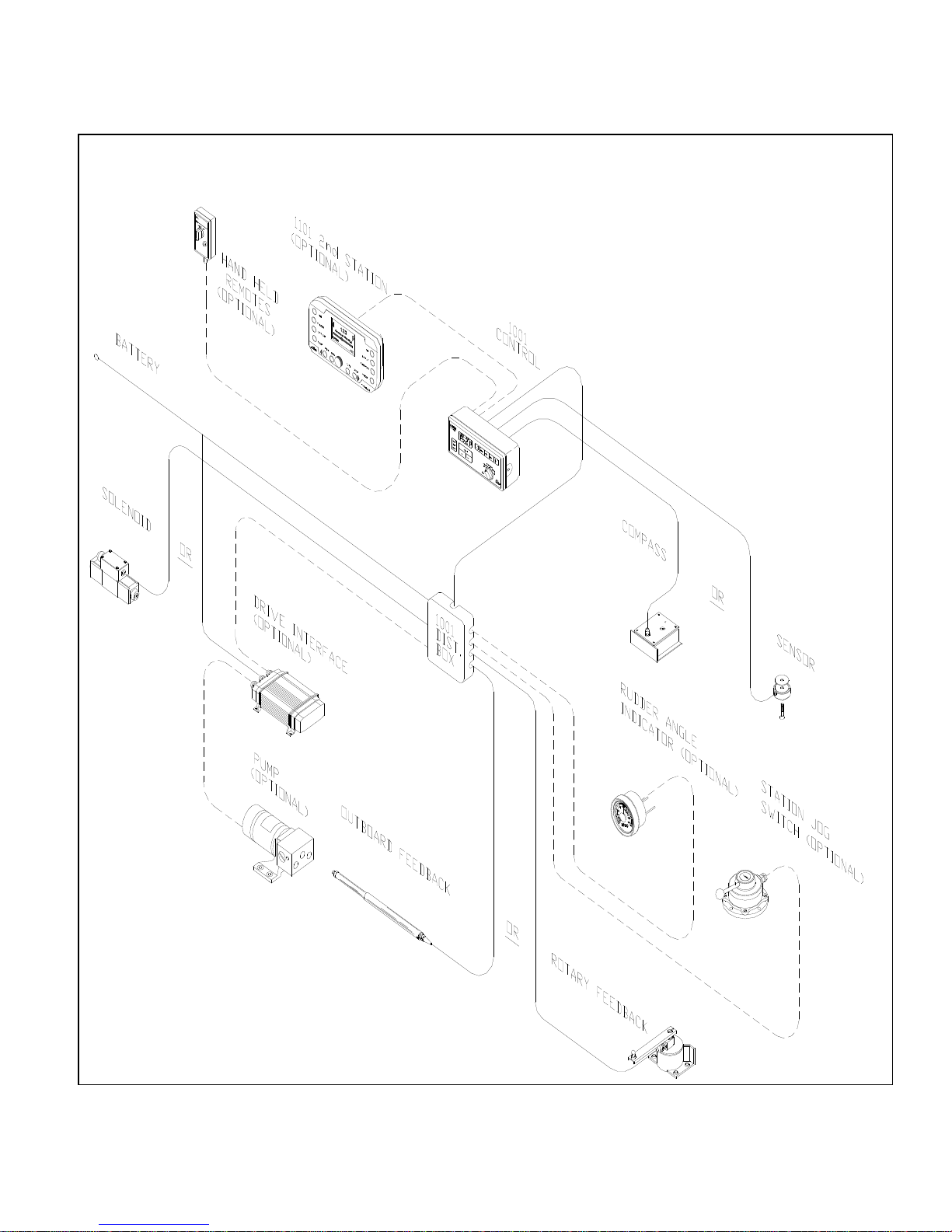
1001 AUTOPILOT SYSTEM DRAWING
3
Page 7

BASIC OPERATION
AUTOPILOT
1. TO INITIALIZE THE AUTOPILOT\
STANDBY MODE
z Turn the master select switch to
the STANDBY position. The display will
show the vessel's current compass
heading. If the heading displayed by the
autopilot does not agree with the
compass, press the ADJUST key twice to
display the current heading offset, and
then use the up or down ARROW key to
adjust the offset by the amount of the
error.
z To turn on the speed sensitivity
that switches between FAST and SLOW
when in PILOT or NAV, with the Pilot in
Standby press the ADJUST key until
'SP: 0' is displayed. Press the up
ARROW key until the desired speed is
displayed.
z To turn off the speed sensitivity,
press the down ARROW key until the
display reads 'SP: 0'.
z If the display is too bright or too
dim when viewed in full darkness, press
the ADJUST key until 'Lt ' is displayed,
and then use the up or down ARROW
key to adjust the minimum brightness
level between 0-9.
z To select a Special Turn as
described in (4) below, press the TURN
key followed by either the red or green
ARROW key.
z To initiate a Full Reset, press and
hold both the up and down ARROW keys
for one second. This will reset all autopilot
parameters back to factory settings and
the Pilot will go into Reset mode. A
dockside set-up will be required after
every Full Reset.
2. TO POWER STEER THE VESSEL\
POWER STEER MODE
z To turn the rudder to port and to
starboard, turn the master select switch to
the POWER STEER position. While
either the red or green ARROW key is
pressed, the display will show the
vessel’s rudder angle and will show the
vessel's current compass heading at all
other times.
z To display the vessel's rudder
angle, press the TURN key once. To
return compass information to the display,
press the TURN key again.
z To zero the digital rudder angle
display, turn the rudder to dead ahead,
press the ADJUST key until the flashing
rudder angle display appears and press
the up or down ARROW key until the
rudder angle display shows ' :00'.
3. TO BEGIN AUTOPILOT CONTROL
OF THE VESSEL:
z To have the vessel continue on its
present heading under autopilot control,
turn the master select switch to the
PILOT position.
z To select either the 'FASt' (High
Speed) mode or the 'Slow' (Low Speed)
mode, press the ADJUST key once
followed by the up or down ARROW key.
This will be done automatically if the
speed sensitive switching has been
turned on in (1) above.
z To adjust the rudder gain setting
for the High or Low speed mode, press
the ADJUST key until 'rud' is displayed,
followed by the up or down ARROW
keys. Similarly adjust the counter rudder
('ctr') and yaw ('YAW') settings for best
steering.
4
Page 8

4. TO CHANGE THE VESSEL'S
COURSE:
z To obtain the desired course,
leave the master select switch in the
PILOT position. Estimate the number of
degrees of course change required.
z Until the display shows the desired
course, alter the course in one degree
steps by pressing and releasing either the
red or green ARROW key.
--- Or --Alter course by ten degrees per second
by pressing and holding either the red or
green ARROW key.
z To select a special turn (U-turn,
Emergency Turn, or Continuous Turn),
with the Pilot in Standby mode, press the
Turn key once followed by the Green key
until the desired Turn is displayed.
z To adjust the rate at which the
vessel will turn to the new course, press
the ADJUST key until 'trn' is displayed
and then press the up or down ARROW
key
5. TO DODGE THE VESSEL OFF
COURSE\PILOT MODE
z To avoid obstacles in the water,
press either the red or green DODGE key
for a panic turn in the desired direction.
z To keep the vessel off course,
after it has turned far enough to clear the
obstacle, press and hold both DODGE
keys.
z To return to the programmed
course at the rate set by the turn rate
control. Release the DODGE key
6. TO INTERFACE WITH A
NAVIGATION COMPUTER\NAV MODE
z Start navigating towards a
selected route or waypoint, using a
Navigation Computer which has an
NMEA 0183 output.
z Turn the autopilot master select
switch to the NAV position. The autopilot
will set its own course using information
sent to it by the Navigation Computer.
z To select the response to cross
track error (normal or reversed), press the
TURN key and then the green ARROW
key.
z The DODGE keys operate as
described in (5) above, except that the
vessel will return to the original track to
the waypoint, rather than the original
course, when the DODGE keys are
released.
For more complete operating instructions,
refer to the CONTROLS and
OPERATION sections.
5
Page 9

REMOTE CONTROL
The autopilot master control unit must be on to use any remote control. The
vessel’s compass heading is shown at all times on the display of the unit that is
NOT in control. As a further reminder, the function indicator (see Figure 8) will be
flashing on the display of the unit that is NOT in control.
1. TO USE THE COMNAV 101
REMOTE CONTROL:
z To take control at the Remote,
press both its pushbuttons for one
second. The command point on all
displays will move to the REMOTE
position. This control operates identically
to the autopilot, except that there is a
toggle switch, used together with one of
the pushbuttons, to dodge or to initiate a
special turn.
z To recall the vessels last course,
hold the toggle switch in the DODGE
position while turning the master select
switch from POWER STEER to PILOT.
The course that the autopilot was steering
when it was last in PILOT will be recalled.
(If the autopilot has not been in PILOT
since it was turned on, the course the
vessel was on at the moment the
autopilot was turned on will be recalled.)
2. TO USE THE COMNAV 1101
SECOND STATION:
z To take control at the Second
Station, press both DODGE keys for one
second. The Command Point on all
displays will move to the REMOTE
position.
z The 1101 second station operates
identically to the autopilot, except that the
OFF/FUNCTION will not operate. The
autopilot must be turned ON and OFF
from the autopilot front panel.
3. TO TAKE CONTROL AT THE
AUTOPILOT FRONT PANEL:
z To take control at the autopilot
front panel, press both the red and green
ARROW keys on the autopilot front panel
for one second. The command point on
all displays will move back to the
MASTER position.
For more complete operating
instructions refer to the REMOTE
CONTROLS section.
WARNING
If the unit that will take control is
not in the same mode as the unit
currently in control, a sudden
course change could occur.
6
Page 10

This autopilot is a microprocessor
operated PID (Proportional-IntegralDifferential) controller, working from either
a high quality, externally gimballed
magnetic ships steering compass fitted
with a fluxgate sensor or a direct earth’s
field sensing fluxgate compass.
Heading information is compared against
the programmed heading, and the
desired rudder position determined. The
desired rudder position is compared
against the actual rudder position
transmitted by the rudder follower. If they
are not the same, either the Port or
Starboard output line is activated.
The Port and Starboard output lines are
active low (i.e. switch to ground), and can
drive a load of up to 3 amps. They are
designed to operate solenoid valves in a
hydraulic steering system.
A speed control signal is also available for
use with variable speed rudder drives.
The outputs, either by themselves or with
an optional solid state drive box, can be
adapted to operate a wide variety of
power steering systems.
If the autopilot is installed as a retrofit, it is
usually possible to use the existing power
steering installation. The autopilot can
operate from either 12 or 24 VDC power
systems.
The autopilot has our unique Ghost
Rudder feature. In case of a rudder
follower failure the autopilot will
automatically switch to Ghost Rudder,
which calculates the rudder position
instead of measuring it, and continue to
operate at a reduced performance level.
INTRODUCTION
The autopilot is equipped to interface with
a GPS, Loran C, or any other navigation
computer which outputs one of the NMEA
0183 formats at 4800 Baud.
The autopilot is designed to accept one
remote control.
By adding the optional REMOTE
EXPANDER, the autopilot can support
any combination of up to four remote
controls or second stations.
Figure 1 shows the possible
interconnections between the autopilot,
it’s accessories, and external equipment.
7
Page 11

SPECIFICATIONS
Operating Voltage: 10 VDC TO 30 VDC
For Use With 12 or 24 VDC Battery Systems only
Operating Current: 0.18 Amps (minimum)
Operating Temperature Range: -15 To +60 °C
Heading Resolution: 0.25 Degree
Heading Accuracy: +
Course Set Resolution: 1.0 Degree
PORT/STBD Output Type: Open Collector, 3 Amps Max
Speed Control Output: 2.50 VDC for No Movement
5.00 VDC for Maximum Speed Port
0.00 VDC for Maximum Speed Starboard
10K ohm Source Impedance
Navigation Input: NMEA 0183 (4800 BAUD): RMA, RMB, RMC, APB,
Rudder Angle Indicator Output: +
Size
Wide: 8.25 inches (210mm)
High: 3.75 inches (95mm)
Deep: 2.25 inches (57mm)
3.0inches(76mm) required behind unit for cabling
Weight: 4.0 lbs (1.6 kg)
2.0 Degrees
APA, XTE, BOD, WBD, HSC, VBW, VHW, VTG
500 Micro-Amp Full Scale Deflection
8
Page 12
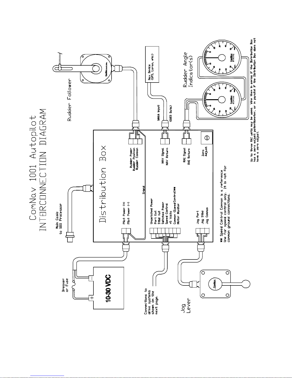
1001 AUTOPILOT INTERCONNECTION DIAGRAM
9
Page 13
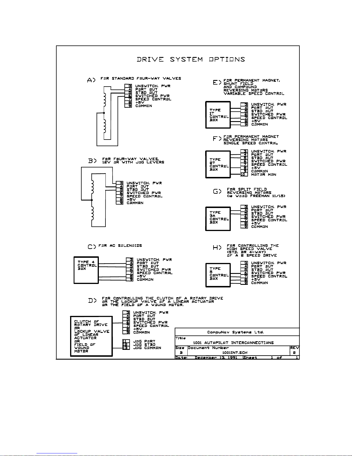
DRIVE SYSTEM OPTOINS
10
Page 14

For all commercial and pleasure
vessels over 50 ft where heavy usage
will be the norm (hydraulic steering):
And
- Belt Driven Pump
Or
- Direct Driven Pump
For vessels with hydraulic cylinder
displacements from 7 to 18 cu.in.):
For vessels with hydraulic cylinder
displacements from 15 to 30 cu.in.):
For vessels with hydraulic cylinder
displacements from 30 to 60 cu.in.):
For pleasure vessels with mechanical
steering up to 70 feet:
To retrofit to vessels with an existing
autopilot drive system which uses a 2
wire (permanent magnet), 4 wire (shunt
field), or 5 wire (compound) reversing
electric motor:
To retrofit to vessels with an autopilot
drive system using a 3 wire (split field)
reversing electric motor:
To retrofit to vessels with an autopilot
drive system using a 12 or 24 VDC
solenoid operated 4-way valve:
To retrofit to vessels with an autopilot
drive system using a 110 or 220 VAC
solenoid operated 4-way valve:
To retrofit vessels with an autopilot
drive system using proportional valve:
Regardless of the type of drive unit being used, the hardover to hardover time must
be checked. For peak performance this time must be 10 - 15 seconds.
OPTIONAL DRIVE SYSTEMS
- CPUFC Flow Control Uniblock
12, 24 or 32 VDC
or
- CPUTS & CT5 - Two Speed Uniblock
12, 24 or 32 VDC
- 18CI Reversing Motor Pump &
CT2-20A Drive Box (12 or 24 VDC)
- 30CI Reversing Motor Pump &
CT2-20A Drive Box (12 or 24 VDC)
- 60CI Reversing Motor Pump &
CT2-20A Drive Box (12 or 24 VDC)
- Hydraulic Linear Actuator &
CT2-20A Drive Box (12 or 24 VDC)
- CT2-20A or CT2-40A Single Speed
Reversing Electric Motor Drive
- CT3 Split Field Reversing Electric Motor
Drive Box
- Nothing Extra Required (consult factory
on 32 VDC systems)
- CT4 AC Solenoid Drive Box
(100 to 240 VAC)
- CT6 or Z-Drive Isolation Amplifier
(consult with factory)
11
Page 15

INSTALLATION INSTRUCTIONS
AUTOPILOT
The autopilot is normally mounted in the
vessel's wheelhouse. It can also be
mounted in a more exposed location,
such as the flying bridge of a sports
fisherman, (if it is flush mounted and the
rear of the autopilot is protected from
spray).
Select either the bag containing the flush
mount bezel and cutting template, or the
bag containing the mounting bracket and
knobs.
BRACKET MOUNT
z Position the mounting bracket so
that the front of the autopilot will be easily
visible. There must be a minimum of
three inches (76 millimetres) of clearance
behind the autopilot to allow for cabling.
z Screw the knobs part way into the
threaded holes on both sides of the
autopilot rear cover. Insert the autopilot
into the mounting bracket, making sure
that the rubber spacer is between the
cover and the bracket, and the plastic one
is between the bracket and the head of
the knob. Tilt the autopilot to the desired
angle, and tighten the knobs securely.
FLUSH MOUNT
z Ensure that there is at least five
inches (127 millimetres) of depth in the
mounting cavity to allow clearance behind
the autopilot for cabling.
z If the autopilot is being flush
mounted in an exposed location, care
should be taken to ensure that the rear of
the autopilot is not exposed to salt spray
or other moisture. The flush mount bezel
reduces the effectiveness of the sealing
gasket on the rear of the autopilot.
z Position the cutting template on
the panel where the autopilot is to be
mounted, and mark the opening onto the
panel. Cut the opening in the panel
around the outside of the markings. To
improve the seal on the rear of the
autopilot, an extra gasket for the rear
cover has been supplied.
z Unscrew the two large screws
from the rear of the autopilot and remove
the rear cover. Peel the protective
backing off the extra gasket, and carefully
position it on top of the one already in the
rear cover.
z Apply the protective gasket to
the back of the flush mount bezel.
z Slide the flush mount bezel over
the autopilot chassis, and replace the rear
cover and screws. Tighten the screws
only enough to slightly compress the
gaskets. Slide the autopilot into the hole
in the panel, and mark the positions of the
four mounting holes. Use the supplied
screws to mount the autopilot.
z If you have access to the rear of
the mounting panel, the autopilot can be
easily removed from the panel by simply
unscrewing the two large screws in the
rear and sliding the autopilot out, without
having to remove the bezel from the
panel.
z The autopilot is supplied with a
cover over the remote control receptacle
on the back. If the receptacle is unused,
the cover should be left on. The
receptacle is weather-resistant only with
the cover on or when a plug is connected
to it. Damage caused by exposing a
receptacle to the elements will NOT be
repaired under warranty.
12
Page 16

COMPASS
FOR COMNAV FLUX-GATE COMPASS
z The compass MUST be mounted
as close as practical to the vessels centre
of pitch and roll. This is typically low in the
vessel, at about the waterline, and slightly
aft of the centre of the vessel.
z You must keep the compass at
least three feet away from engines,
electric motors, and other magnetic
objects. If this is not possible, their effects
may be compensated for as described in
the SEA TRIALS section of this manual.
z To reduce or eliminate the effect of
the vessels vertical field, a HEELING
ADJUST control is provided on the
ComNav Fluxgate Compass, (although
the sensitivity to the earth’s vertical
magnetic field remains.)
z Because of the sensitivity of the
fluxgate compass to the earth's vertical
magnetic fields, it is NOT recommended
for use at latitudes higher than 50
degrees (North or South).
z Use the HEELING ADJUST
control on the compass to eliminate the
effect of the vessel's vertical magnetic
field as described in the SEA TRIALS
section of this manual. The HEELING
ADJUST control is turned OFF when it is
in the centre of its travel.
z Plug the end of the cable into the
compass receptacle on the rear of the
autopilot. If the length of cable supplied
with the compass is not adequate, obtain
an extra plug-in length from your dealer.
Cutting and splicing the compass cable is
NOT recommended.
FOR OTHER FLUXGATE COMPASSES
z The autopilot can be used with a
Fluxgate Compass which outputs DC
Sine and Cosine signals of up to +/- 3
volts amplitude about a 0 to 6 VDC
reference.
z If the compass does not have a
HEELING ADJUST control (i.e. other
makes of fluxgate compasses), it should
NOT be used on steel vessels either.
z The interface has been tested with
Fluxgate Compasses manufactured by
KVH, Brookes and Gatehouse, and VDO.
Some of these compasses have to be
specially ordered in order to have the
required DC Sine and Cosine outputs.
z The autopilot has been supplied
with a 10 ft cable which is plugged into
the Compass receptacle on the rear of
the autopilot. The other end of the cable
is terminated in flying leads. See 0 for
colour & function of each lead.
z +12 Volts will appear on the wire
connected to Plug Pin 7 when the
autopilot is turned on. Up to 100 milliamps
can be supplied by this wire to power the
fluxgate compass.
z If the compass is separately
powered, the tinned ends should be cut
off of the wires connected to Plug Pins 7
& 4. The wires should then be taped back
against the cable to prevent accidentally
shorting out the +12V power supply inside
the autopilot.
Any other unused wires should also have
their tinned leads cut off and be taped
back against the cable.
13
Page 17
CONNECTION FOR NON-1001 FLUXGATE COMPASSES
PLUG PIN
NUMBERS
1001
FLUXGATE
COMNAV
FUNCTION
NON-COMNAV
CONNECTIONS
1 BLUE COSINE COSINE *
2 RED DRIVE P1 N/C
3 BLACK DRIVE P2 N/C
4 SHIELD GROUND GROUND
5 WHITE REFERENCE REFERENCE
6 YELLOW SINE SINE *
7 GREEN +12V +12V
* If the reading is reversed, swap these two wires.
z In testing, the Brookes and
Gatehouse Halcyon 3 compass proved to
have a 'floating' reference. The reference
from the autopilot is also 'floating'. In
order for the interface to work, one of the
references must be fixed to a voltage.
The reference is fixed to +2.5 Volts inside
the autopilot by selecting Compass Type
3 (CPS.3) during the Dockside Set-up.
Compass Type 2 (CPS.2) should be
selected for all other fluxgate compasses.
z If the reading on the Digital Display
of the autopilot increases when the
heading of the vessel is decreasing,
reverse the Sine and Cosine leads.
z If the reading on the autopilot
display does not agree with the vessel's
actual heading, place the Master Select
Switch on the autopilot in the STANDBY
position and press the ADJUST key twice
to display the compass offset. Then press
either the up or down ARROW key to
adjust the offset by the amount of the
error.
z If the compass is selfcompensating, do not run the autopilot
compensation routine during Dockside
Set-up (press either the up or down
compensating, run the autopilot
compensation routine to correct the
compass during Dockside Set-up (press
the ADJUST key when 'CAdJ' is shown
on the display).
MAGNETIC COMPASS
z The advantage of using a
magnetic compass with a fluxgate sensor
is that the autopilot is sensing the position
of the magnets on the compass card
rather than sensing the earth's magnetic
field directly.
z As the card of the compass has
physical inertia, it does not react
immediately to the changes in the
magnetic field it is immersed in, but only
to those changes which persist long
enough to overcome the resistance of the
compass card to movement.
This means that the compass is a more
stable heading reference than a fluxgate
compass. The magnetic compass will
largely ignore changes in the magnetic
field in the plane of the compass card
caused by vessel motion that the fluxgate
compass will react to.
ARROW key when 'CAdJ' is shown on
the display).
z If the compass is not self-
14
Page 18

This is particularly important in high
latitudes, (such as Alaska, Labrador or
the North Sea), where the horizontal
component of the earth's magnetic field
(which is the portion the compass is trying
to detect) is very small relative to the
magnetic field of the vessel.
z The disadvantage of the magnetic
compass is that in very rough weather
with the vessel going to windward, it is
possible for the vessel motion to upset or
'tumble' the compass card, disabling the
autopilot.
z Because of the relative insensitivity
of the magnetic compass to both the
earth's and the vessel's vertical magnetic
fields, (due to its inertia), it IS
recommended for use at latitudes higher
than 50 degrees (North or South), AND
for use on steel vessels when the optional
quadrantal spheres are included.
z Locate and mount the compass in
a position which minimizes magnetic
interference. It should be at least three
feet away from such equipment as
radios, radars, depth sounders, and
engine instruments.
z The compass can be used as a
steering compass if desired. If the amount
of cable supplied is too short to reach the
rear of the autopilot, obtain an extra plugin length of cable from your dealer.
Cutting and splicing the compass
cable is NOT recommended.
z To reduce the possibility of the
card 'tumbling' in rough weather, mount
the compass as close as practical to the
centre of pitch. Mounting the compass
far forward under a bunk or similar
location is a poor choice for rough
weather performance.
15
Page 19
IMPORTANT
It is important to remember that the compass is a vital part of the autopilot system. Locating it properly,
particularly on steel hulled vessels, is essential to ensure proper operation of the autopilot. We
recommend that the services of a qualified compass adjuster be used to select the best installation
location and to compensate the compass properly for deviation, including that caused by heeling error.
Care must be taken not to place compensating magnets too close to the compass, as this will cause
the Fluxgate Sensor, mounted underneath the compass, to read incorrectly. To correct compass
deviation on steel vessels, or on other vessels with magnetic compensating problems due to
interference from adjacent iron masses such as an engine block or winches, the use of a pair of 3-1/4
inch (83 millimetre) Compensating Quadrantal Spheres is recommended.
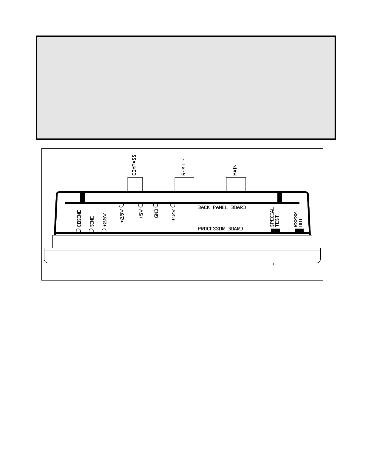
Figure 4 -Test Points
MOUNTING THE SENSOR TO NONSTANDARD COMPASSES
The fluxgate sensor supplied with the
autopilot can be mounted to a wide
variety of "externally gimballed"
compasses. The sensor should not be
mounted to "internally gimballed"
compasses (where the compass card is
gimballed and the bowl of the compass is
not), because the compass card does not
remain parallel to the sensor when the
vessel rolls or pitches, resulting in large
errors between the compass and
autopilot.
Mounting the sensor above the compass
reduces the possibility of compensating
magnets interfering with the operation of
the sensor, but also reduces the visibility
of the compass if it is to be used as a
steering compass.
Remove the rear cover from the autopilot.
Fasten a pair of voltmeter probes
between the SIN and +2.5V testpoints on
the Processor Board (see figure 4).
Turn the master select switch on the
autopilot to the STANDBY position. Hold
the sensor either above or below the
compass, and rotate it until a maximum
level is observed on the voltmeter.
16
Page 20

Move the sensor towards or away from
the compass until a new maximum level
is observed. This is the optimum distance
from the compass to mount the sensor.
Any closer and the sensor may interfere
with the operation of the compass.
The accuracy of the sensor, and its
sensitivity to external fields, will slowly
weaken as it is moved further from the
compass. If the reading on the autopilot
display decreases when the heading on
the compass is increasing, turn the
sensor over. Rotate the sensor until the
heading on the display of the autopilot
matches the reading on the compass,
and tighten the mounting screw.
Rotate the compass through 360
degrees, comparing readings every 20
degrees. The readings should agree
within +/- 2 degrees (4 degrees total
error) if the compass is compatible with
the sensor.
As a further test, tilt the bowl of the
compass so the card tilts relative to the
sensor. The heading on the display of the
autopilot should not change more than
two degrees, with the compass still
indicating the same heading.
If the heading changes more than two
degrees, the magnets on the compass
card are not powerful enough, and the
compass is not compatible with the
sensor.
If the accuracy of the compass and
sensor combination cannot be made at
least +/- 2 degrees, then the compass is
not compatible with the autopilot sensor.
Your dealer can supply a compass
specifically designed for the ComNav
1001 autopilot.
17
Page 21

DISTRIBUTION BOX
Position and mount the distribution box
underneath or inside the control console
in a DRY location so that the main cable
from the distribution box will easily reach
the rear of the autopilot. Cables are
inserted into the distribution box by filing
or cutting out the pre-formed ports in the
cover. To ensure a neat appearance, the
cover has only had the minimum number
of openings prepared in advance.
The suggested types and gauges of
cables required to hook up the
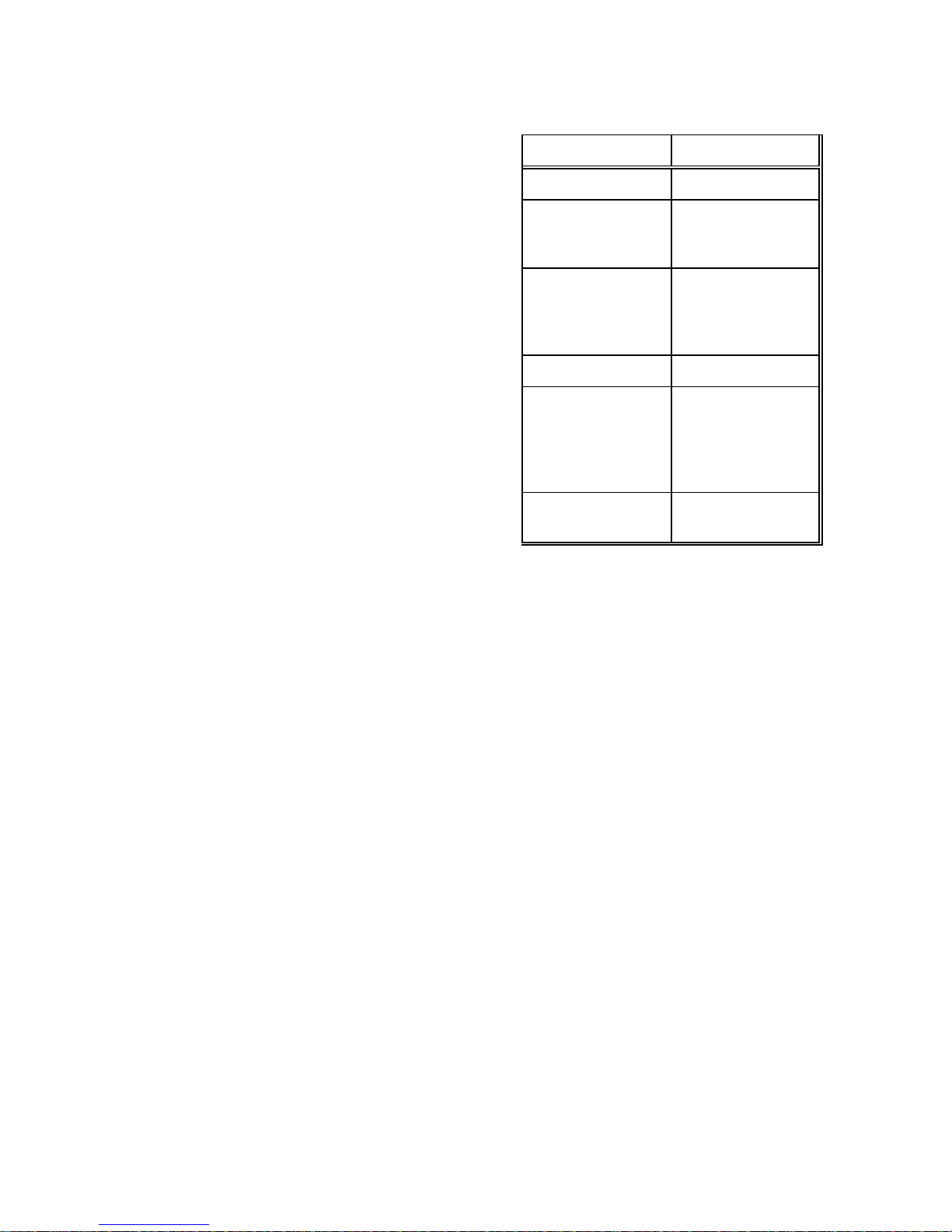
autopilot are listed in Table II.
The functions of each set of connections
in the distribution box are as follows:
1. POSITIVE PILOT POWER (+)
2. NEGATIVE PILOT POWER (-)
These two terminals should be hooked to
a source of DC power on the boat. The
voltage can be from 10 to 27.5 VDC. The
maximum current requirement is less
than 4 amps. The autopilot is negative
ground.
For vessels with positive ground, or with
multiple power sources (i.e. AC and DC
power sources) the autopilot control head
should be electrically isolated from the
vessel. This can be accomplished by
mounting it to a non-conducting material,
such as wood or fibreglass. This will
prevent any damage from ground
currents.
The power should be taken directly from
a breaker or power distribution panel. The
autopilot should have its own circuit. This
circuit can also send power to the drive
unit.
If the drive unit is a reversing electric type,
it should be wired back to the breaker
separately from the autopilot (i.e. do NOT
wire from the breaker to the drive unit,
and then from the drive unit to the
autopilot). The combined current
requirement of the autopilot and any
reversing electric drive unit manufactured
by ComNav Marine will not exceed 30
amps.
3. UNSWITCHED POWER
The input voltage appears on this terminal
at all times when the breaker which
supplies power to the autopilot is on. If a
12 VDC solenoid operated 4-way valve is
being used, wire this terminal to the
common of the solenoid valve to ensure
an adequate voltage supply.
If Jog Levers are being used, and are to
be active even with the autopilot turned
off, wire this line to the common of the
solenoid operated 4-way valve.
WARNING
If the UNSWITCHED PWR terminal is
used and there is a malfunction of the
autopilot or jog lever which continuously
activates the 4-way valve, the only way to
deactivate the 4-way valve is to turn off
the breaker which supplies power to the
autopilot.
18
Page 22

4. PORT STEERING OUTPUT
5. STBD STEERING OUTPUT
These are the two main steering outputs
from the autopilot. They are open
collector (i.e. switch to ground) and can
sink up to 3 amps of current. They can be
used directly to operate a solenoid
operated hydraulic 4-Way Valve, or as
inputs to a solid state drive box for electric
steering systems (either hydraulic or
mechanical).
Either output can be overridden with a
switched connection (such as a jog lever)
between JOG PORT or JOG STBD and
JOG COM (terminals 11, 12, and 13)
without damaging the autopilot. A pair of
diagnostic LED's, one red and one green,
are provided in the distribution box to
confirm the correct operation of these two
outputs.
6. SWITCHED POWER
The input voltage appears on this terminal
when the autopilot is in any mode except
STANDBY or OFF. It can supply up to 3
amps of current for use as the power
source for a solenoid operated 4-Way
Valve, or to activate an electric steering
system.
A yellow diagnostic LED is provided in the
distribution box to confirm the correct
operation of this output. For 12V 4-Way
Valve operation, it is recommended that
this output not be used; instead, the
common lead from the solenoids should
be connected to UNSWITCH. PWR
(terminal 3).
7. SPEED CONTROL
This is a linear signal used with variable
speed drive systems. It is centred
between +5 VOLTS and COMMON
(terminals 8 and 9) when no change of
rudder angle is required, and moves up or
down from that point by as much as 2.5
VDC for maximum rudder position
change to port or starboard respectively.
8. +5VDC
9. COMMON
+5 volts appears across these terminals
whenever the autopilot is turned on.
These terminals are used by several of
the Drive Boxes manufactured by
ComNav Marine as a reference for
SPEED CONTROL (terminal 7).
A yellow LED is provided in the
distribution box to confirm the operation of
the 5V power supply in the autopilot.
Terminal 9 must NOT be used as the
return for a motor field or the clutch or a
rotary drive or the lockup valve of a linear
actuator; JOG COMMON (Terminal 13)
or PILOT POWER (-) (Terminal 2) should
be used instead.
10. MOTOR MONITOR
This terminal is used with some of the
Drive Boxes manufactured by ComNav
Marine to monitor motor current. If the
current exceeds a maximum level, the
autopilot will sound an alarm.
11. JOG PORT
12. JOG STBD
13. JOG COMMON
If any jog levers are being used in the
system, they should be connected to
these three terminals. If the jog levers are
to be active all the time, whether the
autopilot is turned on or off, connect the
common from the solenoid valve to
UNSWITCHED POWER (terminal 3).
14. RUDDER POWER
19
Page 23
15. RUDDER POSITION
16. RUDDER COMMON
Table II - RECOMMENDED CABLES
These three terminals connect to the
rudder follower. With the cable from the
distribution box unplugged from the rear
of the autopilot, and the rudder turned to
dead ahead, the resistance between
RUDDER POWER and
RUDDER POSITION, and RUDDER
POSITION and RUDDER COMMON
should be equal, and each measure
approximately 600 ohms if you are using
a ComNav Rudder Feedback.
17. NAV SIGNAL
18. NAV RETURN
These two terminals connect to the
NMEA 0183 output of a Loran C
Receiver, GPS Receiver, or other type of
navigation device so equipped. Whenever
the autopilot is turned on, the LED next to
these terminals will light while data is
being received.
19. RAI SIGNAL
20. RAI RETURN
These two terminals are used to run up to
three ComNav Marine rudder angle
indicators. Multiple rudder angle indicator
installations must be wired in series. If all
the indicators move to port when the
rudder is moving to starboard, reverse the
connections to these terminals. If only
one of the indicators moves to port when
the rudder is moving to starboard, reverse
the connections at that indicator only. Use
the ZERO ADJUST potentiometer on the
Distribution Box circuit board to make the
indicators read zero degrees when the
rudder is dead ahead.
USE TYPE
Pilot Power 2 X 16 GAUGE
-Steering Drive12/24/32VDC
Solenoid Valve
-Steering DriveCT2,CT3,CT4,
CT5 and CT6
Drive Box
Rudder Follower 3 X 18 GAUGE
Navigation
Interface
Rudder Angle
Indicator
3 X 18 GAUGE
Refer to the
Instructions
Supplied with
Drive Box
2 X 24 GAUGE
with OVERALL
SHIELD. Shield
terminated at the
Nav Device ONLY
2 X 24 GAUGE
20
Page 24
RUDDER FOLLOWER
The rudder follower is used to transmit
the position of the rudder back to the
autopilot. It should be connected to
whatever part of the steering system the
autopilot controls. Normally, this will be
the vessel's rudder. However, if the
vessel has 2 stage steering, such as
Wagner M10, Kobelt Power Steering or a
similar system where the autopilot drives
a control or servo ram, the rudder follower
should be mounted to the servo ram
rather than to the rudder. If the rudder
follower is connected directly to the
rudder in this case, uncontrollable hunting
of the rudder will result.
Normally the rudder follower is mounted
in the stern of the vessel, close to the
rudder post. A mounting base may have
to be fabricated to position the rudder
follower properly. Mount the follower in a
location where the possibility of damage
from any equipment stowed in the area is
minimized.
If a Medium Duty rudder follower was
supplied:
Mount the rudder post arm on the rudder
post using a stainless steel band clamp
(not supplied). Bolt the ball joint to the
hole in the rudder post arm corresponding
to the diameter of the rudder post in
inches, making sure the ball is facing
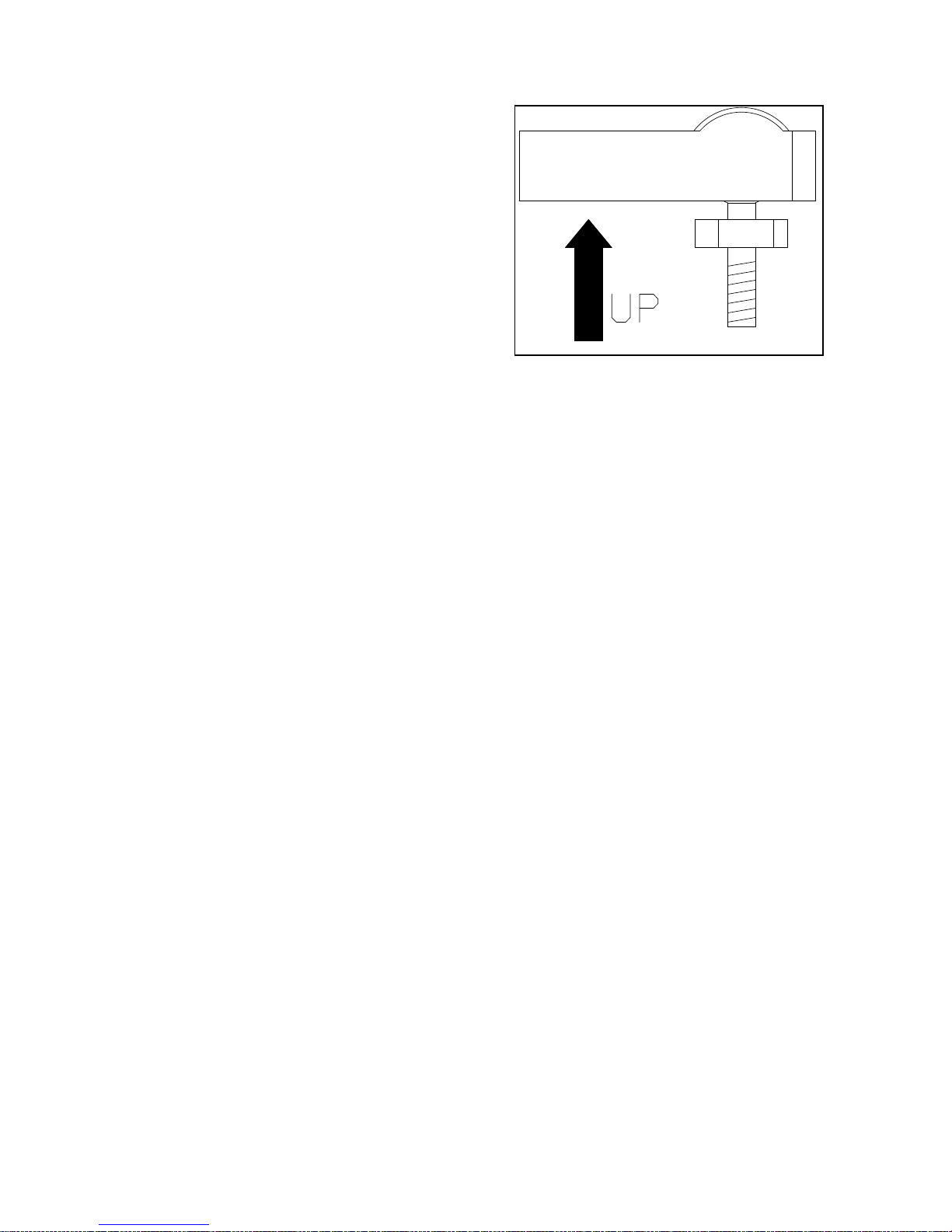
upwards (see Figure 5). Mount the rudder
follower so that the rudder follower arm is
the same height as the rudder post arm.
The rudder follower is centred when the
arm is directly above the cable gland.
(See figure 6 for alignment details.)
Figure 5 - Correct Linkage Orientation
If a Heavy Duty rudder follower was
supplied
Mount the rudder follower so that the top
of the vessel's tiller arm is 1 3/4 inches
lower than the top of the rudder follower
arm. On the centerline of the vessel's tiller
arm, and within 3 to 5 inches from the
centre of the rudder post, either:
- drill and tap a hole 1/4-20
or
- drill a clearance hole for a
1/4 inch bolt if enough of
the threads of the supplied
ball joint will come through
the tiller arm to permit the
supplied nut to be threaded
onto it.
The rudder follower is centred when the
arm is pointing away from the cable gland
and is directly over the stainless rivet in
the top cover. (See Figure 6 for
alignment details.)
21
Page 25
With either rudder follower.
The distance between the centerline of
the rudder post and the rudder follower
must not exceed 24 inches. Make sure
that the ball joints on the rudder arm and
rudder follower arm are facing upwards
as shown in Figure 4. Snap the rod
assembly onto the ball joints. Be sure to
close the release clamps on each socket.
Refer to Figure 5 or Figure 6 and adjust
the length of the rod to get the correct
geometry with the rudder dead ahead.
Table III - Rudder Follower Cable
Connections
Colour Terminal Description
White 14 +5V
If the length of cable supplied is too short
to reach all the way to the distribution box,
obtain a terminal strip and sufficient
additional cable from your dealer. Mount
the terminal strip in a convenient DRY
location. Connect the rudder follower
cable to the terminal strip and then the
additional length of cable. Strip the wires,
and attach them to the terminals in the
distribution box as shown Table III
Green 15 POS'N
Black 16 COM
Shield 2 GND
If the locking screw in the rudder follower
arm has been loosened, or the arm
removed from the rudder follower, reattach the arm and check the
potentiometer centring. When the rudder
is dead ahead, the electrical resistance
between the Black and Green wires and
the White and Green wires should be
equal (approx. 600 ohms each).
Be careful to check the installation for any
mechanical obstructions or binding of the
linkage, and correct it now, before it
becomes a problem.
The rudder follower is supplied with 50
feet of cable. Run the cable from the
rudder follower towards the distribution
box, ensuring that it is protected by hose
or conduit wherever it passes through fish
or cargo holds, or any other area where it
could be damaged.
22
Page 26
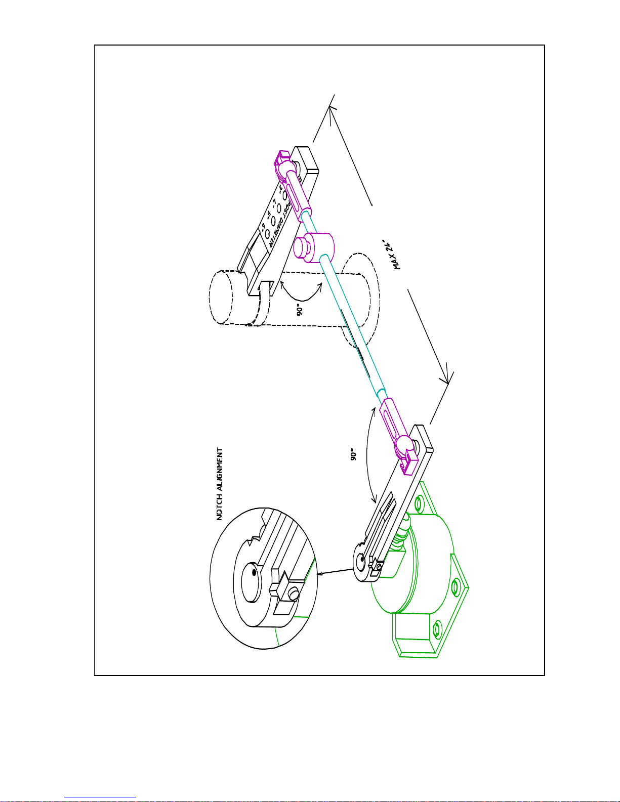
Figure 6 - Rudder Feedback correctly installed to rudder post
23
Page 27

NAVIGATION INTERFACE
If the autopilot is being interfaced to a
navigation device with several NMEA
outputs, determine the type of output
formats available from its data sheets.
The 1001 autopilot will only support
NMEA 0183 data format and therefore
that format must be selected. If your
navigation device only outputs 0180 or
0182 formats, please consult with
ComNav service personnel to receive
software that will support these older style
formats.
NMEA 0183
The standard baud rate for the 0183 data
format is 4800 baud.
This data format was developed to allow
a number of pieces of electronic
equipment on the vessel to communicate
with each other. It consists of a large
number of data 'sentences' which can
transmit anything from the vessel's water
speed to its present position from one
device to another.
A data sentence consists of a two letter
identification of the sending device,
followed by a three letter identification of
the data sentence, followed by the
corresponding information.
The autopilot can understand a number of
data sentences that contain steering or
speed information. The autopilot ignores
the two letter device identifier, and only
looks for the three letter sentence
identifier, so it will receive information
from any Nav Device which transmits the
correct data sentences.
Some NMEA 0183 data sentences supply
heading from the beginning of track to the
end of the track, which remains constant
until the Nav Device sequences to the
next waypoint. This is the best type of
Heading To Steer information, as it
prevents the wandering which may occur
when the vessel is close to the
destination waypoint as described earlier.
Depending on the type of Nav device and
how it is configured, the autopilot may
sound its alarm and display 'Arr' when the
vessel is close to a waypoint.
24
Page 28

The variations of NMEA 0183 which are currently supported by the autopilot along
with the information the autopilot uses from that sentence are listed below:
RMA
RMC
The RMA or RMC data sentence is always combined with the RMB data sentence.
RMB
APB
APB
APA
XTE
XTE is always combined with one of the following:
BOD
WBD
HSC
The vessel's speed is read from the RMA or RMC data sentence or one of the
Loran C Navigation Information - Receiver
Status plus Vessel Speed plus Variation
GPS Navigation Information – Receiver
Status plus Vessel Speed plus Variation
Generic Navigation Information - Cross Track
Error plus Heading To Steer from vessels
present position to the end of the track
(Degree's True only).
Autopilot Interface Format - King Version Cross Track Error plus Heading To Steer from
the vessel's present position to end of track.
Autopilot Interface Format - NMEA Version Cross Track Error plus Heading To Steer from
the vessel's present position to end of track.
Autopilot Interface Format - Cross Track Error
plus Heading To Steer from beginning to end
of track.
Cross Track Error - Cross Track Error plus
Receiver Status.
Bearing Origin to Destination – Bearing from
the beginning of the track to end of the track.
This is the preferred heading format, or;
Waypoint Bearing and Distance – Proprietary
output from Northstar Lorans. Heading to Steer
is from the vessel's present position to the end
of the track;
Heading Steering Command – Heading To
Steer from the vessel's present position to the
end of the track.
25
Page 29

following:
VBW
Vessel Speed relative to water from Dual
Doppler Speed Log.
VHW
Vessel Heading and Water Speed
VTG
Vessel Track and Ground Speed
CROSS TRACK ERROR RESPONSE
The response of the autopilot is set with
the master select switch in the NAV
position.
Press the TURN key, and then the green
ARROW key to select normal indicated
by an 'n' on the right of the display, or
reversed indicated by an 'r ' on the right of
the display response to cross track error.
If the setting is incorrect, the vessel will
initially turn to the correct heading, but
then as some cross track error develops,
the vessel will continually turn further and
further away from the correct heading to
the waypoint.
Cross Track Error contains two pieces of
information; the amount of the error, and
the 'sense' of the error (i.e. whether the
vessel is to the Left or the Right of the line
between the beginning and ending
waypoints).
The NMEA National Marine Electronics
Association has specified how the cross
track error should be identified (i.e. a
(L)eft indicator in the data sentence
means the vessel should steer to the left
and a (R)ight indicator meaning the
opposite).
However, some manufacturers have used
the (L)eft indicator to mean that the
vessel is to the left of the line, which
means the vessel should steer to the
right, and the (R)ight indicator to mean
the opposite.
Because of this confusion, the response
of the autopilot to cross track error can be
switched from 'Normal', meaning the
vessel will respond normally to the sense
of the cross track error, to 'Reversed',
meaning the vessel will respond the
opposite way in response to the same
information.
26
Page 30

CHECKSUM EVALUATION
During testing it was discovered that
some Navigation Devices incorrectly
calculate the checksum, causing the
checksum error message to be displayed
repeatedly.
The checksum evaluation can be turned
off by turning the master select switch to
STANDBY and press the ADJUST key
repeatedly until 'cn:ON' is displayed.
Press either the up or down ARROW key
until 'cn:OF' is displayed.
**** IMPORTANT ****
If you have installed a ComNav Marine reversing motor pump, a constant running pump or
an engine driven pump, there are several checks that must be done during the first several
weeks of usage in order to prevent poor or dangerous steering performance. During this
period you must check for air or leaks in your hydraulic system.
Residual air in your steering system
Following the initial installation and bleeding of your ComNav pump, some residual air may
remain suspended in the hydraulic fluid. During the first few weeks, this air will gradually
bleed out through the header tank or the highest helm pump and the oil level may go down.
Check several times and add more oil as required.
Leaking fittings or equipment
Following the initial installation and bleeding of your ComNav pump continuously monitor
the oil level of the reservoir or the highest helm pump in your steering system and add oil
as required. If this condition persists, it may be an indication of leakage in your steering
system. Check all hydraulic steering fittings and equipment for leakage.
The RMA, RMB and RMC data
sentences contain a 'checksum' which is
determined by the contents of the
sentence. The autopilot can calculate
what the checksum should be and
compare it to the sentence. If the
sentence was received correctly , the two
checksums should be the same. If they
are different the autopilot assumes that
the sentence was incorrectly received and
displays 'cn:Er'.
27
Page 31

DOCKSIDE SET-UP
INTRODUCTION
It is essential that the DOCKSIDE SETUP procedure be performed before taking
the vessel out on the water.
This procedure will be much easier to do
if you have a helper, especially if you
don't have a rudder angle indicator
(R.A.I.).
NOTES
Always turn the autopilot to OFF
before making any changes to the
wiring in the distribution box. Failure
to do so could cause serious damage
to the autopilot in the event of a
dropped wire, a misconnection, or
similar problem.
It is VERY IMPORTANT to manually
turn
SETTING OF RUDDER TRAVEL LIMITS
1. Turn the autopilot to OFF. Press
and hold the ADJUST key on the
autopilot front panel and then turn the
autopilot on to STANDBY.
2. Release the key when 'r.SEt' is
shown on the autopilot display. Press the
ADJUST key briefly. The autopilot will
show 'HO S' on the display.
3. Manually turn the wheel hard over
to starboard and then press the green
ARROW key. The autopilot will then show
'HO P' on the display.
4. Manually turn the wheel hard over
to port and then press the red ARROW
key.
The goals of the dockside set-up are:
1. To set the limits of the rudder
travel.
2. To adjust the R.A.I.
3. To configure the compass.
4. To make sure that the navigation
interface is properly connected.
the rudder from hard over to hard over
and check that the rudder follower
does not hit anything and that the
linkage does not bind. (Part of the
dockside set-up consists of automatic
rudder movements by the autopilot
and damage could result if the rudder
follower is installed incorrectly.)
If the autopilot detects a problem with the
output from the rudder follower during this
procedure, it will display the message
'rEdO'. If this happens turn the autopilot
off and recheck the rudder follower
installation as described in the
INSTALLATION section of the manual.
(In particular, check that the rudder
follower is electrically centred when the
rudder is dead ahead.) Start this section
again.
5. The autopilot will show 'Cntr' on
the display. Turn the wheel to
approximately dead ahead using the
wheel. Then press the ADJUST key.
28
Page 32

The autopilot will turn on the starboard
output for 2 seconds. If the rudder moved
to port, the autopilot will sound its alarm
and flash the word 'Stbd' on the display.
6. Turn the autopilot to OFF, reverse
the PORT OUT and STBD OUT leads
(terminals 4 and 5) in the distribution box.
Start this section again.
7. If the hard-over to hard-over time
(H.O. Time) is greater than 28 seconds in
either direction, the autopilot will alarm
and display 'SLOW' until the ALARM
CLEAR key is pressed. The autopilot will
then complete the dockside set-up
routine.
ADJUST RUDDER ANGLE INDICATOR (if installed)
Turn the master select switch on the
autopilot to the STANDBY position.
Center the rudder.
Turn the wheel to port and then to
starboard. If the rudder angle indicator
moves to port when the rudder moves to
starboard, reverse the RAI SIGNAL and
RAI RETURN leads (terminals 19 & 20) in
the distribution box.
Please note that no vessel will steer
properly, especially in rough weather,
with an H.O. Time over 28 seconds.
For most vessels under 100 feet, we
recommend that the H.O. Time be 8 to
16 seconds.
The smaller and faster the vessel, the
faster the rudder should move.
For example a 30 foot high speed
vessel should have an H.O. Time
closer to 8 seconds, and an 80 foot
low speed vessel would not require
the H.O. Time to be faster than 16
seconds.
If the rudder angle indicator(s) do not
read 0 degrees when the rudder is dead
ahead, adjust the ZERO ADJUST
potentiometer on the distribution box
circuit board until they do.
29
Page 33

CONFIGURING THE COMPASS
1. The autopilot will show 'C.SEt' on
the display, when the setting of the
rudder limits is complete. Press the
ADJUST key briefly and the display will
change to show the type of compass to
be selected.
CPS.1 is a magnetic compass and
fluxgate sensor
combination.
CPS.2 is a fluxgate compass with
a fixed voltage reference
output. Most fluxgate
compasses including
ComNav Marine, KVH
(Azimuth or Sailcomp) and
VDO are of this type.
CPS.3 is a fluxgate compass with
a floating reference output.
The only compass of this
type we know of is the
Brookes & Gatehouse
Halcyon III.
NAVIGATION EQUIPMENT INTERFACING
1. Turn on the Nav Device (GPS,
Loran, Plotter, etc.) and wait for it to settle
and extinguish all alarms.
2. Program a waypoint into the Nav
Device, and start it navigating towards the
waypoint.
3. Turn the Master Select Switch on
the autopilot to the NAV position. The
heading display on the autopilot should
start to change towards the heading to
steer as indicated by the Nav Device.
Press the TURN key once to see which
type of data the autopilot is using to verify
correct programming of the Nav Device.
2. Press either the up or down
ARROW key until the type of compass
selected is the same as the type of
compass being used.
3. Press the ADJUST key. The
display will change to show 'C.AdJ' if you
have selected either CPS.2 or CPS.3.
As we don't want to swing the compass
yet, press either the up or down ARROW
key to exit from the set-up program.
To verify your heading, turn the master
select switch to the STANDBY position.
The display will show the vessel's current
compass heading. If the heading
displayed by the autopilot does not agree
with the compass, press the ADJUST key
twice to display the current heading
offset, and then use the up or down
ARROW key to adjust the offset by the
amount of the error.
If the autopilot display comes up with
'ndEr', it is not receiving any data from
the Nav Device.
Check that the Signal and Return lines
from the Nav Device are not reversed,
and that the output from the Nav Device
is set correctly if it is programmable.
Check that the data LED in the autopilot
distribution box is blinking periodically.
If the interface still cannot be made to
work, contact your dealer or ComNav
Marine directly for assistance.
30
Page 34
SEA TRIALS
The purpose of sea trials is to swing the compass, (CPS2 or CPS3) if it is a fluxgate
compass, and to check the general operation of the autopilot.
CAUTION: A potentially dangerous situation can be caused by the addition or
movement of magnets in the vicinity of the compass. This can result in actual
deviations being different than those listed on the deviation card.
If the autopilot is using a magnetic compass
and fluxgate sensor combination or a self
compensating fluxgate compass (such as the
KVH Autocomp 1000), go to B.
A) Turn the autopilot off.
Press and hold the ADJUST key and turn
the autopilot on to STANDBY.
Release the key when the display shows
'r.SEt'.
Press either the up or down ARROW key
until the display shows 'C.SEt'.
Press the ADJUST key. The display will
switch to show the current type of
compass selected (see DOCKSIDE
SETUP). This should already be correct.
Press the ADJUST key again. The
display will switch to show 'C.AdJ'.
Press the ADJUST key again. The
display will switch to display 'turn'.
Slowly turn the vessel in one complete
circle either to port or to stbd. This is best
done with either the bowthruster or by
placing one engine slow ahead and the
other slow astern.
If the vessel has one engine and no
bowthruster, slow ahead with the rudder
half-way to hard-over is best. The turn
should take more than one minute to
complete.
When the circle is complete, the autopilot
will beep and display first a North/South
correction followed by an East/West
correction.
If either correction is greater than 30, the
compass should be moved and re-swung,
or corrected manually by a qualified
compass adjuster.
If you choose to correct the compass
manually, use the following procedure:
Turn the autopilot off.
Press and hold the ADJUST key while
turning the autopilot on to STANDBY.
Release the ADJUST key when the
display shows 'r.SEt'.
Press either the up or down ARROW key
until the display shows 'C.SEt'.
31
Page 35

Press the ADJUST key. The display will
switch to show the current type of
compass selected. This should be
already correct.
Press the ADJUST key. The display will
switch to 'C.AdJ'.
Press either the up or down ARROW key
to bypass the compass adjustment
routine. All adjustments have now been
turned off, and the raw compass
information is now shown on the display.
The compass adjuster can use this
display to adjust the compass manually.
After the compass adjuster is finished, reswing the vessel using the automatic
method described above to remove any
minor errors which may persist.
The ComNav Marine Fluxgate
Compass, like most self compensating
compasses, removes the effect of the
deviating magnetic field, but does not
actually remove the field itself.
If the field is sufficiently large, when the
vessel rolls, the portion of the field in the
plane of the sensor changes, and is
interpreted as a turn by the compass,
causing the vessel to wander.
The compass adjuster, by placing
magnets around the compass removes
the deviating field itself from the vicinity of
the compass, resulting in much more
accurate steering in all sea conditions.
Place the vessel on a known heading.
If the reading on the autopilot display
disagrees with the vessels actual
heading, correct it with a permanent
heading offset.
To do this, place the master select switch
in the STANDBY position, press the
ADJUST key twice to display the heading
offset, and adjust it up or down by the
32
amount of the error using the up or down
ARROW keys.
The display will change back to show the
vessels heading in 5 seconds, which
should now be correct.
If the autopilot is using a ComNav
Fluxgate compass, the final adjustment
is the heeling adjustment.
To access the heeling adjuster, remove
the screw from the top of the compass.
Reach in through the hole with a small
non-magnetic screwdriver to make an
adjustment.
This manual adjustment corrects for any
vertical magnetism in the vicinity of the
compass.
During the remainder of the sea trials, if
the vessel seems to wander on some
headings (particularly North or South)
while steering well on other headings,
turn the heeling adjustment clockwise or
counter-clockwise until wandering stops.
This adjustment may cause some
additional deviation in the compass, so
the compass should be re-swung using
the automatic method after any change of
the heeling adjustment.
B) The 1001 Autopilot offers
instant selection of pre-adjusted FAST
and SLOW vessel control settings.
Adjust or fine-tune these settings to
your vessel characteristics as follows:
FAST
Turn the master switch to PILOT position.
Page 36

Press the ADJUST key once. If the
display reads 'SLOW', press either the up
or down ARROW key once so the display
reads 'FASt'.
Increase the vessels speed to its fastest
normal cruising speed.
Make a 40 degree course change.
The vessel should settle onto the new
course with one overshoot of 5 degrees
or less.
If the vessel stops turning before the
new heading is reached and then
approaches it slowly, either increase
the Rudder one level, or decrease the
Counter Rudder one level and retest.
If the vessel overshoots the new
heading, and then makes several turns
across the new heading before settling
down, either decrease the Rudder one
level, or increase the Counter Rudder one
level and retest.
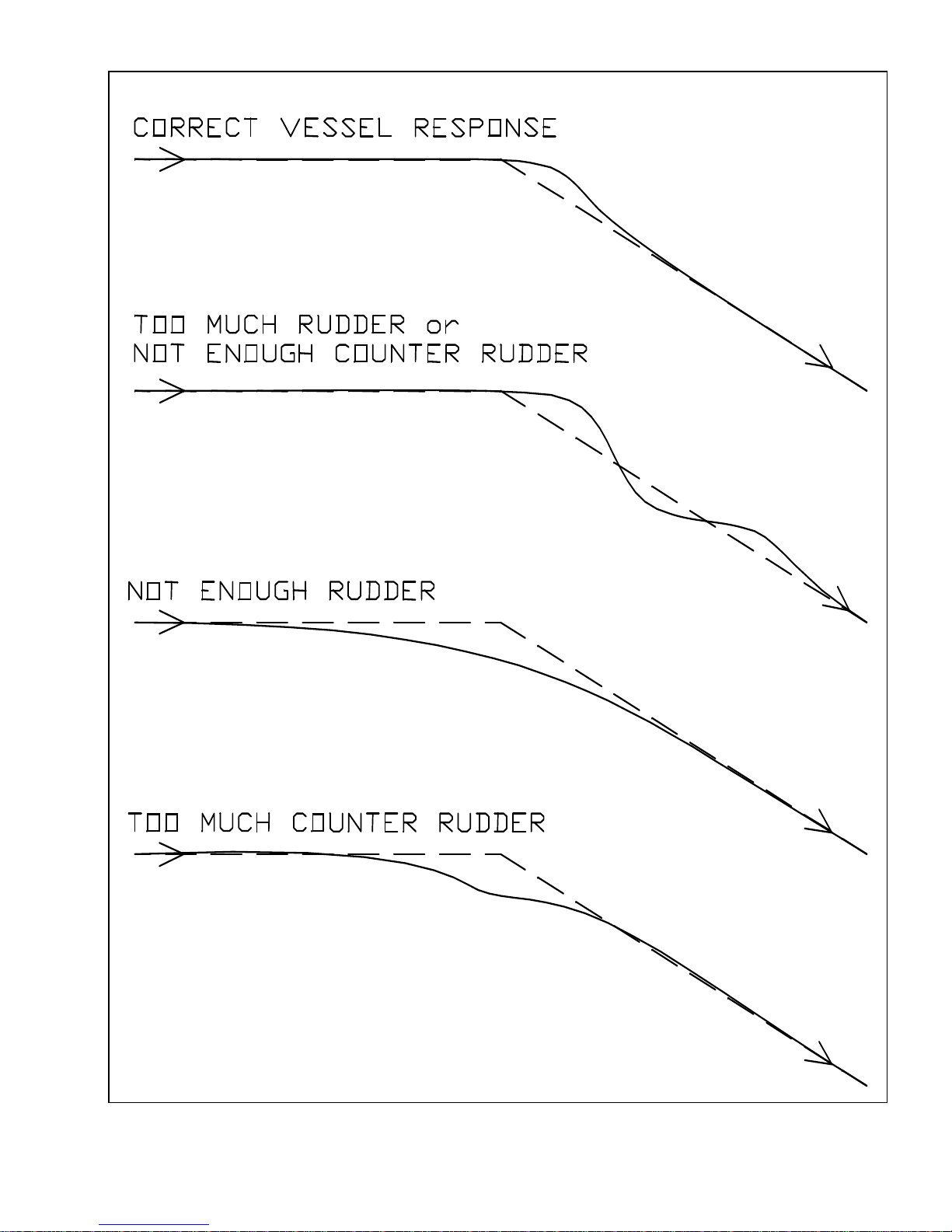
See 0 for a graphic representation of
correct vessel response during this
manoeuvre.
Adjust the fast Turn Rate setting so the
vessel makes course changes at a
comfortable rate.
The factory pre-set adjustments are
Rudder 3; Counter Rudder 3; Yaw 1,
Turn Rate 6.
SLOW
Slow the vessel down to a slow cruise or
to working speed.
Leave the master select switch in the
PILOT position.
Press the ADJUST key once, and then
press either the up or down ARROW key
so the display reads 'SLOW'.
Make several 40 degree course changes
and use the instructions in the "FAST"
section above to adjust the slow rudder
and counter rudder settings.
See 0 for a graphic representation of
correct vessel response during this
manoeuvre.
Adjust the slow Turn Rate setting so the
vessel makes course changes at an
appropriate rate.
The factory pre-set adjustments are
Rudder 5; Counter Rudder 5; Yaw 1,
Turn Rate 6.
C) The Yaw (fast or slow) is normally
left at '1'.
This provides 0.5 degrees of dead band
on either side of the programmed course
before the autopilot will begin to react.
On many vessels, setting the Yaw to '0'
will cause the autopilot to work harder
than necessary to hold the vessel on
course.
As the weather deteriorates, the Yaw
setting can be increased. This will result
in slightly worse steering, but will reduce
the amount of rudder movement,
prolonging the life of the steering system.
D) On board magnetic interference
to the compass is likely the problem, if
the vessel steers properly under autopilot
control on some headings, but seems to
wander on others, particularly heading
either North or South.
33
Page 37
If the autopilot is using a ComNav
Fluxgate Compass, try changing the
heeling adjustment to reduce or eliminate
the problem.
Remember to re-adjust the compass
using the automatic method after any
change of the heeling adjustment.
If this has no effect, return the heeling
adjustment to the centre of its travel, turn
off the automatic adjustment, and have a
qualified compass adjuster compensate
the compass. After the compass adjuster
is finished, re-swing the compass using
the automatic method, as described in
Section A, to remove any small residual
errors.
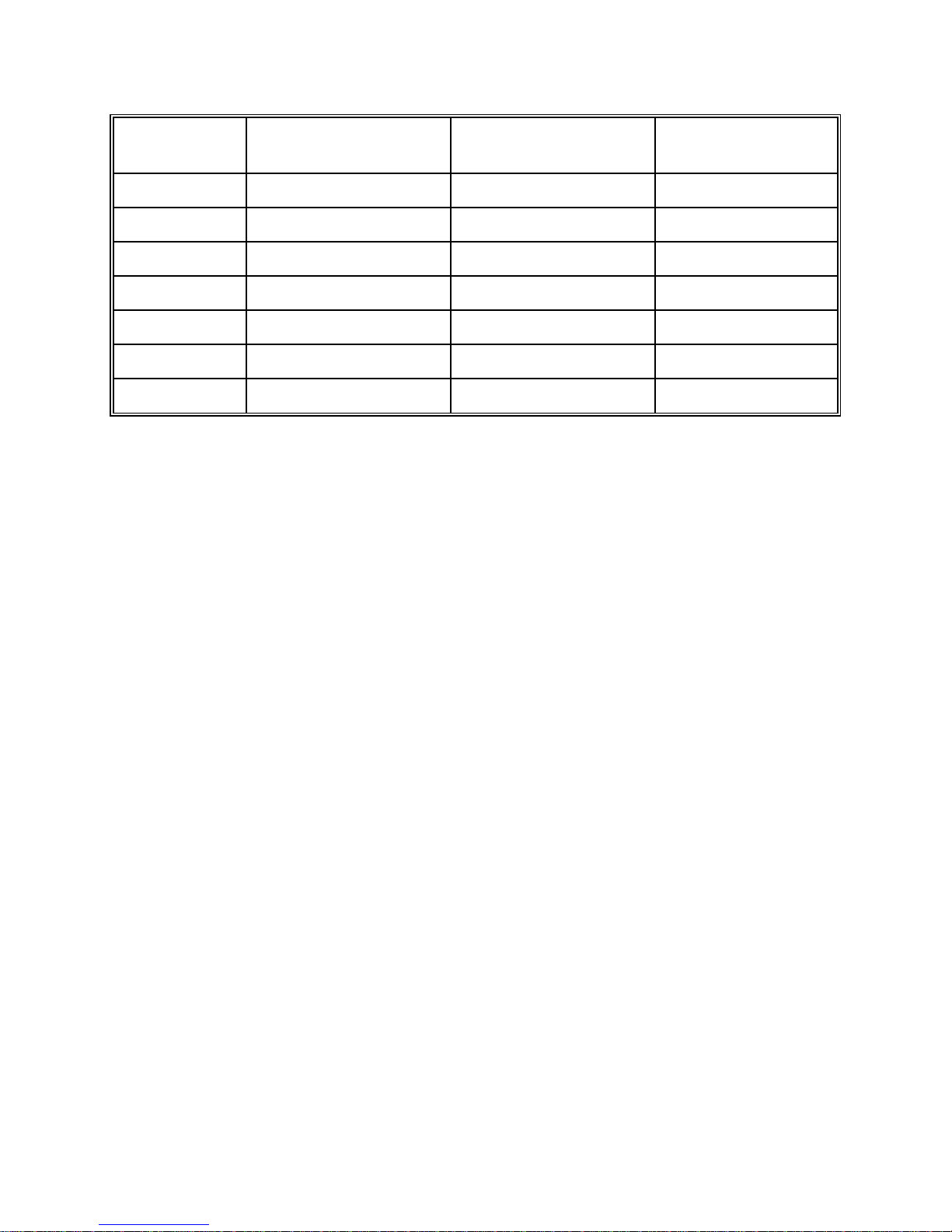
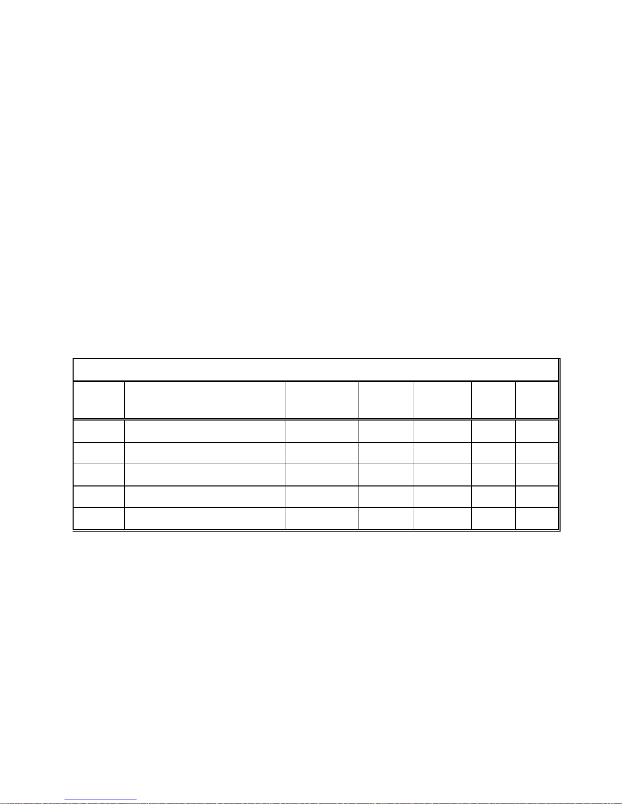
TABLE IV
If the autopilot is using a different
brand of fluxgate compass, or a
magnetic compass with fluxgate
sensor, a qualified compass adjuster will
be required to reduce or eliminate this
interference.
For best operation, in addition to normal
adjustments, the compass should be
compensated for deviation caused by
heeling error (particularly on steel hulled
vessels).
Adjustments of this sort should only
be performed by a qualified compass
adjuster.
SETTINGS CHART
Vessel
Speed
Vessel
State
Sea
State
Rudder Counter
Rudder
Yaw Turn
Rate
34
Page 38
35
Page 39
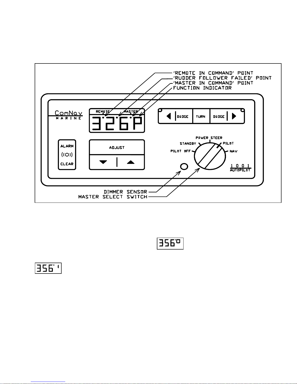
CONTROLS
The controls consist of a five position master select switch, and a 9
position membrane keypad. The controls operate as follows:
MASTER SELECT SWITCH
OFF
All power to the autopilot is turned off.
The display will be blank.
STANDBY
The left three digits of the display show
the vessel's current compass heading.
This is the mode the autopilot must be in
to adjust various pre-sets, such as speed
sensitivity, compass heading offset,
minimum brightness, type of special turn
selected or to initiate a full reset.
POWER STEER
display show the vessel's current
compass heading. The vessel can be
steered by using the red and green
DODGE & ARROW keys to turn the
rudder port or starboard as desired.
The display will switch to show the
vessel's rudder angle whenever a red or
green key is pressed. The display will
continuously show the vessel's rudder
angle if the TURN key is pressed.
Compass information can be returned to
the display by pressing the TURN key
again.
36
The left three digits of the
Page 40

PILOT
The vessel will steer the course indicated
on the left three digits of the display.
The course the vessel is steering can be
changed by pressing either the red or
green ARROW keys.
Pressing and releasing either key will
change the heading by one degree.
Pressing and holding either key will
initially change the vessel's heading by
one degree and after a one/half second
delay, by ten degrees per second until the
key is released. The function display will
show a 'c' until the course change is
completed.
Pressing the TURN key followed by either
the red or green ARROW key will initiate
a special turn (Emergency turn,
Continuous turn, or U-turn; selected in
STANDBY) in that direction.
The function display will show an 'E', 'C',
or 'U' until the turn is completed.
MEMBRANE KEYPAD
The ADJUST key can now be used to
change the Rudder, Counter Rudder,
Yaw and Turn Rate settings.
NAV
Place the master select switch in this
position when the autopilot is being
operated with a navigation computer (i.e.
GPS, Loran, etc.) which has an NMEA
0183 data format output.
The autopilot operates the same way as
in the PILOT position, except that it will
change its course as directed by the
navigation computer to maintain a Zero
Track Error.
The autopilot will display 'Fd:ER' if there
is a problem with the data it is receiving
such as Low Signal To Noise Ratio, Blink
Alarm, or Incorrect Cycle Selection.
The autopilot will display 'nd:Er' and
maintain its last course if it does not
receive any data from the navigation
computer.
ADJUST KEY
Pressing the ADJUST key repeatedly
displays first the Rudder setting, then
the Counter Rudder, Yaw and finally
the Turn Rate setting for either the
FAST or SLOW mode.
Press the ADJUST key followed by either
the up or down ARROW key to switch
between the FAST and SLOW modes.
This will be done automatically if
the speed sensitivity is turned on. Any
setting may be changed between '0' and
'9' while it is displayed by pressing the up
or down ARROW key.
37
Page 41

DODGE KEYS
Pressing either the red or green
DODGE key will dodge the vessel in
that direction.
The display will switch to show the
vessel's rudder angle. Pressing and
holding both DODGE keys will centre the
rudder to hold the vessel off course.
Release the DODGE key(s) and the
vessel will return to its programmed
course.
ALARM CLEAR
The autopilot will sound the alarm
when an error condition exists.
This condition will also be indicated on the
display. The alarm may be cleared by
touching the ALARM CLEAR key. If the
error condition still exists, the alarm will
come on again.
RUDDER
Controls the amount of rudder applied
for a given amount of course error.
At the maximum setting of '9', 3 degrees
of rudder will be applied for each degree
of course error. Every two position
reduction in the setting cuts the amount of
correction applied in half.
COUNTER RUDDER
Controls the amount of rudder applied
for a given rate of change of course
error.
If the course error is increasing, the
counter rudder adds to the rudder
correction applied, and if the course error
is decreasing, the counter rudder
subtracts from the rudder correction
applied. At the maximum setting of '9', 10
degrees of rudder will be applied for a 1
degree per second rate of change of
course error. Every two position reduction
in the setting cuts the amount of
correction applied in half.
YAW
Controls the amount of deviation from
the programmed course the autopilot
will allow before correcting the
vessel's heading.
Increasing the setting will increase the
amount of heading deviation allowed. The
number shown on the display is the
number of degrees of heading deviation
allowed, centred on the programmed
course (i.e. a setting of 4 will allow 2
degree's of heading deviation on either
side of the programmed course, before
any correction is applied).
TURN RATE
Controls the rate at which the vessel
makes a course change, returns to its
original course after a dodge, or
changes course under Nav Device
control.
The turn rate corresponding to each
control setting is shown in Table V
following.
38
Page 42
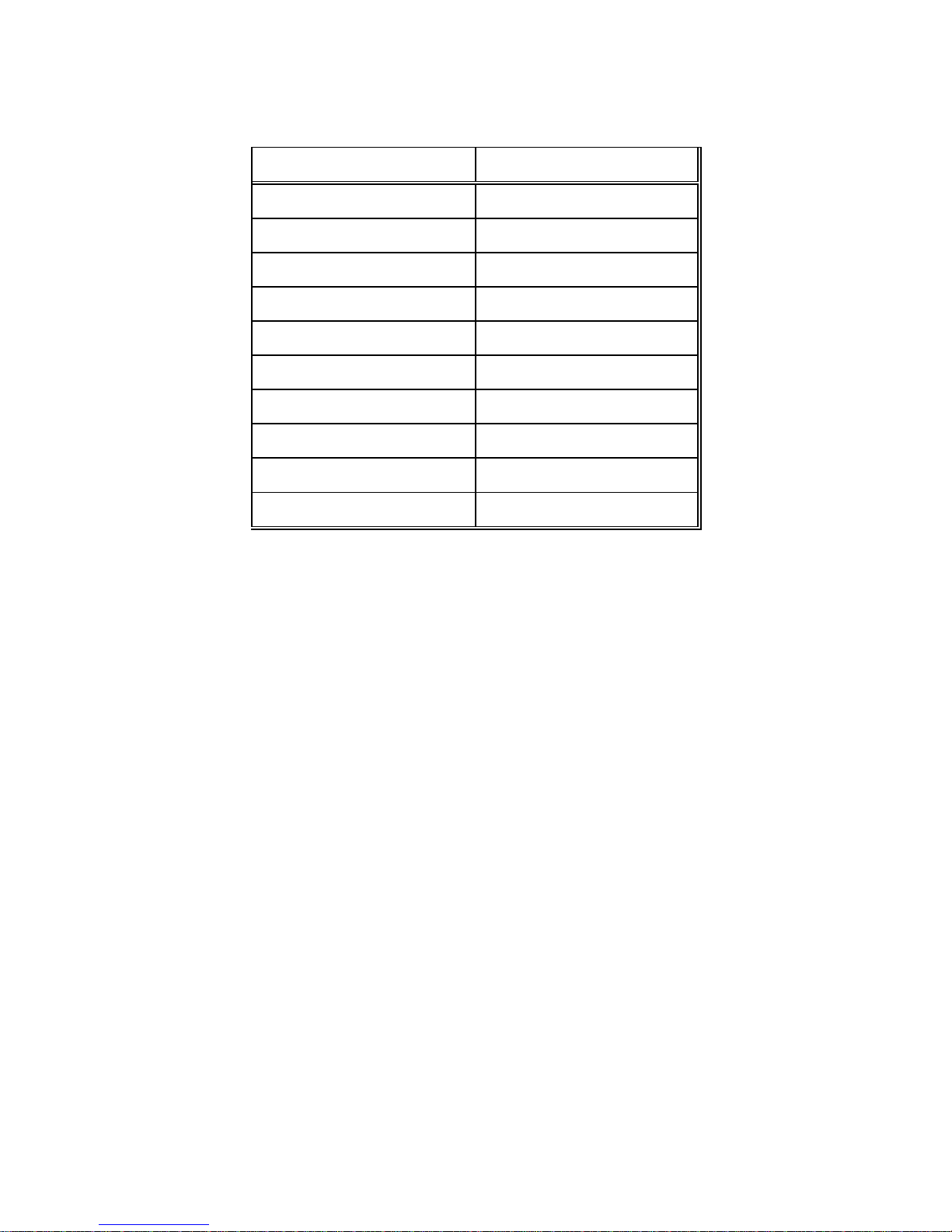
TABLE V:
SETTING TURN RATE
0 0.5 DEG/SEC
1 1.0 DEG/SEC
2 1.5 DEG/SEC
3 2.0 DEG/SEC
4 2.5 DEG/SEC
5 3.0 DEG/SEC
6 3.5 DEG/SEC
7 4.0 DEG/SEC
8 4.5 DEG/SEC
9 5.0 DEG/SEC
39
Page 43
SPECIAL TURNS
When the autopilot is in the PILOT mode, pressing the TURN key followed by either
the red or green ARROW key initiates the PRE-SELECTED type of special turn.
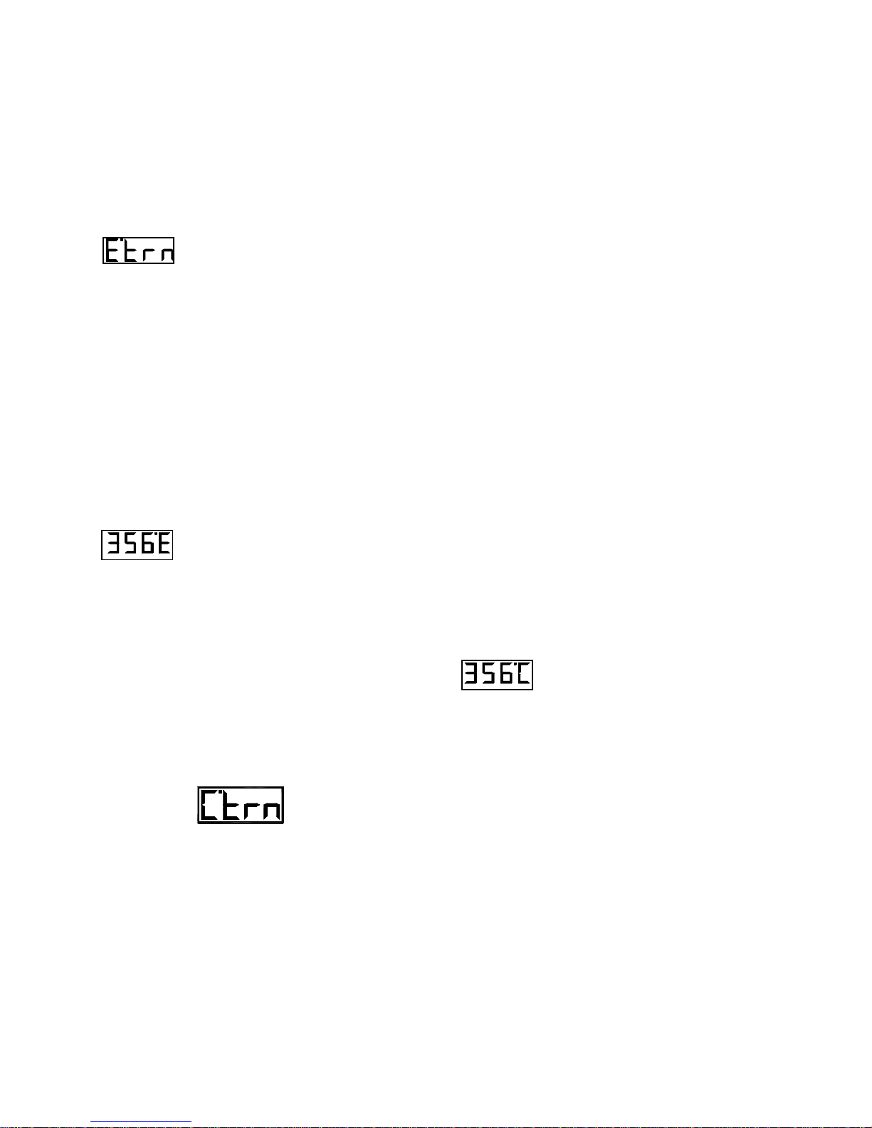
EMERGENCY TURN
The Emergency Turn is selected by
placing the autopilot in the STANDBY
mode, pressing the TURN key, followed
by either the red or green ARROW key
until the display shows 'E.trn'. This turn is
sometimes called the 'man overboard
turn' or 'Williamson turn'. If the vessel's
speed and turn rate are not changed
while the turn is in progress, the autopilot
will bring the vessel about in such a way
that it retraces its own path in the water.
An Emergency Turn to port is
initiated by placing the
autopilot in the PILOT mode and
pressing the TURN key followed by the
red ARROW key. The autopilot will make
a 90-degree turn to port. When that turn is
complete, the autopilot will automatically
make a 270-degree turn to starboard. The
function indicator will change to an 'E'
until both turns are complete. When the
second turn is complete, the vessel
should be retracing its own track in the
water. Pressing the TURN key followed
by the green ARROW key does the same
thing only the first 90 degree turn is to
starboard, and the second 270 degree
turn is to port. The speed at which the
turns are performed is set by the Turn
Rate control, and should not be changed
during the turn (otherwise the vessel will
not end up on its own track).
CONTINUOUS TURN
The Continuous Turn is selected by
placing the autopilot in the STANDBY
mode, pressing the TURN key, followed
by either the red or green ARROW key
until the display shows 'C.trn'.
A Continuous Turn to port is
initiated by placing the
autopilot in the PILOT mode
and pressing the TURN key followed by
the red ARROW key. The vessel will turn
at the rate determined by the Turn Rate
control and will continue to turn until either
the red or green ARROW key is pressed.
The function indicator will show a 'C' until
the turn is stopped. The vessel will then
travel in the direction indicated on the
display. Pressing the TURN key followed
by the green ARROW key will start a
similar turn to starboard.
40
Page 44
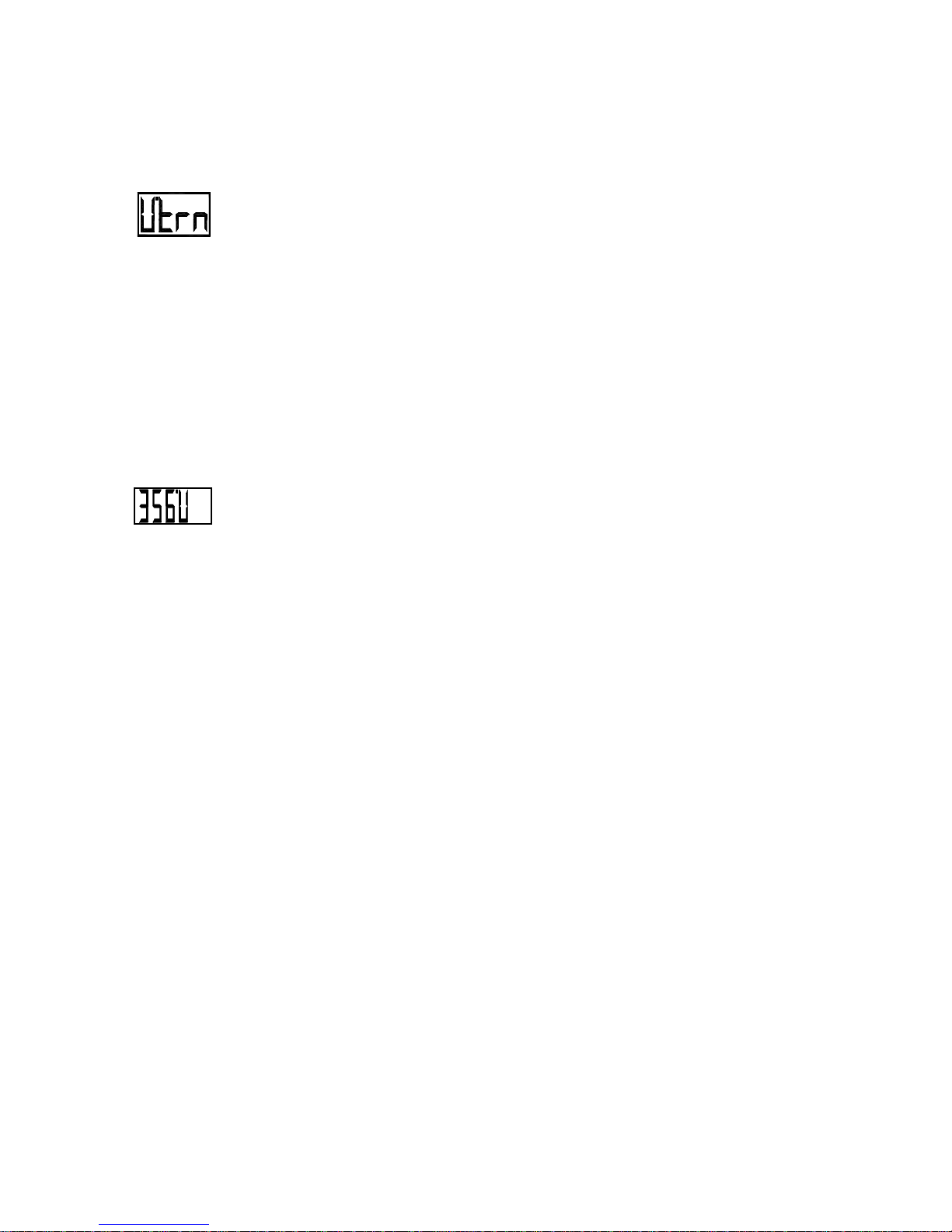
U TURN
The U-Turn is selected by placing the
autopilot in the STANDBY mode,
pressing the TURN key, followed by
either the red or green ARROW key until
the display shows 'U.trn'. This turn is also
just what it sounds like, a 180 degree
turn.
A U-Turn to port is initiated
by placing the autopilot in
pressing the TURN key followed by the
red ARROW key. The vessel will turn to
port at the rate determined by the Turn
Rate control. Pressing the TURN key
followed by the green ARROW key will
start a similar turn to starboard. Pressing
the TURN key followed by the same
ARROW key during the U-turn will
increase it to a full 360 degree turn.
the PILOT mode and
41
Page 45
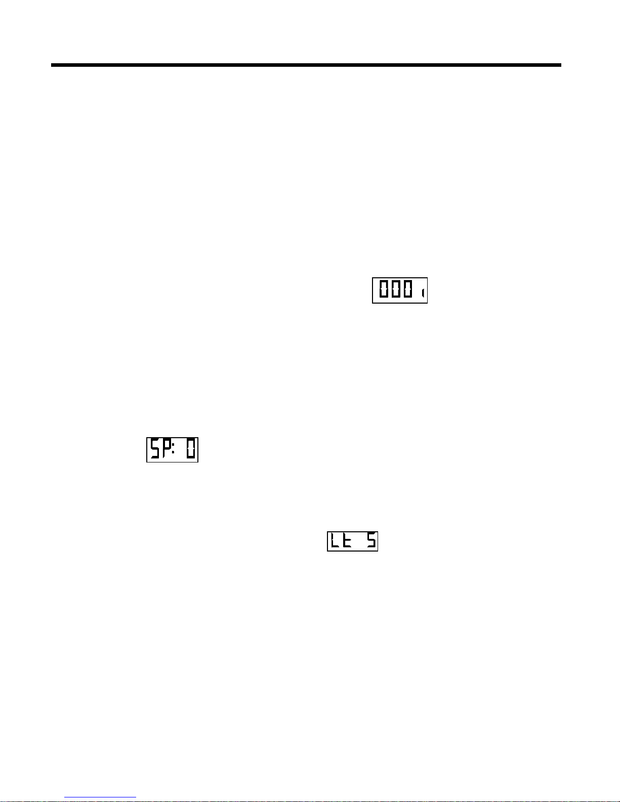
OPERATION
For one second the first thing you will see
when the autopilot is turned on is the
software revision number. Example:
'01.09'. This will tell you the version of the
computer program in your autopilot.
STANDBY
The first operating mode is STANDBY .
In this mode, the display will show you the
vessel's actual compass heading. Any
rudder angle indicators fitted will now
show the vessel's rudder angle.
If the compass heading on the digital
display does not agree with the vessels
actual heading, adjust the heading offset
by the amount of the error. (For example,
if the vessels actual compass heading is
265 and the digital display reads 260, the
offset should be increased by 5 degrees
as described below.)
ADJUST KEY FUNCTIONS IN
STANDBY:
Press the ADJUST key once to adjust the
speed sensitivity.
The speed sensitivity is turned off when
'SP: 0' is displayed.
The autopilot will switch from SLOW to
FAST when any other value is displayed
(when the vessel's speed is one knot or
more higher than the displayed speed)
and from FAST to SLOW (when the
vessel's speed is one knot or more lower
than the displayed speed).
To tell if you have the most current
version of the autopilot program, call the
factory with the software revision number
displayed. If you do not have the latest
version, we will be able to tell you how to
have your autopilot updated.
This feature requires that the autopilot
be interfaced to a navigation device,
preferably a GPS, or plotter driven by a
GPS, that outputs one of the NMEA
0183 RMA, RMC, VBW, VHW or VTG
data sentences.
To display the current compass offset,
press the ADJUST key twice
To increase or decrease the offset, press
either the up or down ARROW key. (An
offset of 005 degrees will add 5 degrees
to the compass heading and an offset of
355 degrees will subtract 5 degrees from
the compass heading.)
The heading offset may need to be as
much as 180 degrees, depending on the
type and brand of compass connected to
the autopilot
To display the current minimum or night
time brightness level, press the ADJUST
key three times.
To increase or decrease the minimum
brightness level, press either the up or
down ARROW key.
42
Page 46
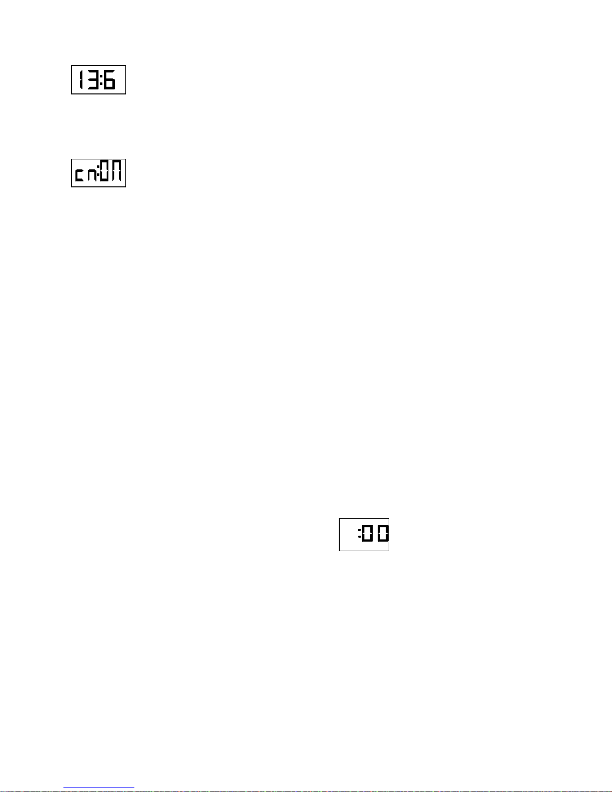
To display the battery voltage supplied to
the autopilot, press the ADJUST key four
times.
To turn the checksum evaluation of the
RMA, RMB and RMC data sentences on
or off, press the ADJUST key five times.
To turn on the checksum evaluation,
press either the up or down ARROW
keys until 'cm:ON' is displayed.
To turn off the checksum evaluation,
press either the up or down ARROW key
until 'cm:OF' is displayed.
POWER STEER
The second operating mode is POWER
STEER. In this mode, the display still
shows the vessel's actual compass
heading, but now the red and green
ARROW or DODGE keys can be used to
turn the rudder port or starboard.
The display will switch to show the
vessel's rudder angle any time a red or
green ARROW or DODGE key is
pressed.
The positive input voltage will appear on
the SWITCHED PWR line to power a
solenoid operated 4-way-valve, or to
engage the clutch mechanism of a drive
unit on a mechanical steering system.
You can still use the wheel if you have
hydraulic steering.
If you have mechanical steering, the only
operating mode where you can use the
wheel is STANDBY.
See the NAVIGATION INTERFACE
section of this manual for more
information.
To change the type of special turn
(Emergency turn, Continuous turn, or Uturn) that will occur when you select a
special turn in the PILOT operating mode,
press the TURN key followed by either
the red or green ARROW key.
To reset all autopilot parameters back to
factory original settings, press and hold
both the up and down ARROW keys for
one second.
A dockside set-up WILL be performed
after a Full Reset. See the DOCKSIDE
SETUP section of this manual for more
information.
The digital rudder angle display can be
locked on by pressing the TURN key.
To return the vessels compass heading to
the display, press the TURN key again.
ADJUST KEY FUNCTIONS IN
POWER STEER
To adjust the digital rudder angle indicator
reading so that it reads zero when the
rudder is dead ahead, press the ADJUST
key once. While the reading is flashing,
press either the up or down ARROW key
to adjust the reading.
43
Page 47
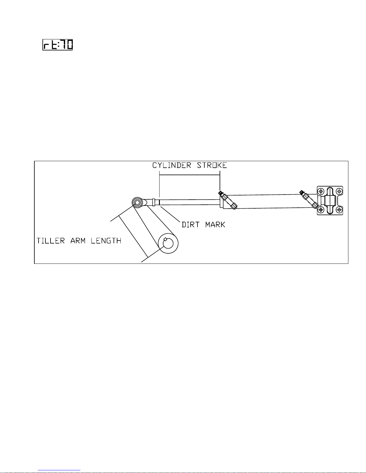
To set the hard-over to hard-over Rudder
Travel, press the ADJUST key twice.
This is used to more accurately calibrate
the digital rudder angle reading and does
not affect how far the rudder moves.
Press either the up or down ARROW key
Rudder Travel can be measured using an
analog Rudder Angle Indicator (if one is
fitted), or by measuring the stroke of the
hydraulic cylinder (Cylinder Stroke) and
the distance from the center of the rudder
post to the point on the tiller where the
cylinder attaches (Tiller Arm Length).
Then calculate the hard-over to hard-over
Rudder Travel using the following
formula.
until the number on the display equals the
actual number of degrees of rudder travel.
Rudder Travel = 2 x Inverse Sine (Cylinder Stroke / (2 x Tiller Arm Length))
Figure 9- Measure Rudder Travel with Wheel Hard Over
PILOT
The third operating mode is PILOT. The
autopilot will begin steering the vessel on
the last course it was on, just prior to
switching to PILOT, when you turn the
master select switch to this position. The
autopilot will use the last rudder angle on
the vessel as the first approximation of
dead ahead rudder.
This means that if you are towing a net
and require 15 degrees of port rudder to
make the vessel steer straight, the
autopilot will hold that rudder angle when
you turn to PILOT.
If the rudder angle is not correct, the
automatic trim function of the autopilot will
find the correct dead-ahead rudder angle
in approximately one minute.
44
Page 48

TO CHANGE THE VESSEL'S COURSE
BY ONE DEGREE, press and release the
red or green ARROW key.
TO MAKE LARGER COURSE
CHANGES, press and hold the red or
green ARROW key, and the display will
move at 10 degrees per second until you
release the key. The autopilot will bring
the vessel around to the new course at
the rate set by the Turn Rate control (see
5).
The Function Indicator will show a 'c' until
the course change is complete.
Press the TURN key followed by either
the red or green ARROW key and the
vessel will make an Emergency turn,
Continuous turn, or U-turn (selected in
STANDBY) in that direction at the
programmed rate of turn.
The Function Indicator will show a 'E', 'C'
or 'U' until the turn is complete.
If a Navigation Device which transmits
any of the RMA, RMC, VBW, VHW, or
VTG sentences is connected to the
autopilot, you may choose automatic
switching between the FAST and SLOW
modes when in Pilot or Nav This works
best if the Navigation Device is a GPS or
a plotter which is driven by a GPS.
THE SPEED SENSITIVITY IS TURNED
ON by rotating the master select switch to
the STANDBY position and pressing the
ADJUST key once. The display will
change to show 'SP: 0'.
Press the up ARROW key until the speed
at which you would like the autopilot to
switch from SLOW to FAST is displayed.
When the vessel's speed is one knot or
more higher than this speed, the autopilot
will switch from SLOW to FAST. When
the vessel's speed is one knot or more
lower than this speed, the autopilot will
switch from FAST to SLOW.
THE SPEED SENSITIVITY IS TURNED
OFF by either manually switching the
autopilot from SLOW to FAST, from
FAST to SLOW, or by rotating the master
select switch to STANDBY and pressing
the ADJUST key once. The display will
change to show 'SP: x'. Press the down
ARROW key until the display shows 'SP:
0'.
If the autopilot fails to receive any speed
information from the navigation device, it
will alarm and display 'NO:SP' once every
twenty seconds.
The ADJUST key can now be used to
adjust the Rudder, Counter Rudder, Yaw
or Turn Rate settings for either the FAST
or SLOW mode.
If the vessel is travelling at high speed,
press the ADJUST key once followed by
either the up or down ARROW key until
the display reads 'FAST'. This will occur
automatically if the speed sensitivity is
turned on.
TO INCREASE OR DECREASE THE
RUDDER SETTING, press the ADJUST
key until the display reads 'rud' followed
by either the up or down ARROW key.
TO INCREASE OR DECREASE THE
COUNTER RUDDER SETTING, press
the ADJUST key until the display reads
'Ctr' followed by either the up or down
ARROW key.
TO INCREASE OR DECREASE THE
YAW SETTING, press the ADJUST key
until the display reads 'YAW' followed by
either the up or down ARROW key.
TO INCREASE OR DECREASE THE
TURN RATE SETTING, press the
ADJUST key until the display reads 'trn'
followed by the up or down ARROW key.
45
Page 49

The factory settings for Rudder,
Counter Rudder, Yaw and Turn Rate
are 3, 3, 1 and 6 respectively.
TO SELECT THE SLOW MODE, (if the
vessel is travelling at slow speed), press
the ADJUST key once followed by either
the up or down ARROW key until the
display reads 'SLOW'. This will occur
automatically if the speed sensitivity is
turned on.
The Rudder, Counter Rudder, Yaw and
Turn Rate settings for the slow mode are
adjusted the same way as described
above.
The factory settings for Rudder,
Counter Rudder, Yaw and Turn Rate
are 5, 5, 1 and 6 respectively.
When in doubt about how to determine
the correct Rudder and Counter Rudder
settings for either the FAST or SLOW
modes, try the factory settings shown
above.
If you make a large turn, and you see that
the vessel overshoots the new course
more than once, try either increasing the
amount of Counter Rudder by one
setting, or reducing the amount of Rudder
by one setting. If this does not solve the
problem try it again.
If the vessel seems to stop turning before
you get to the new course, and then
slowly come up to it, try either decreasing
the amount of Counter Rudder or
increasing the amount of Rudder. Refer
to 0 for a graphic representation of
Rudder and Counter Rudder adjustments.
If nothing seems to make the vessel steer
properly, or it steers properly on some
headings but not on others, particularly
north or south, it is almost always a
problem with the compass.
If the autopilot is using a Magnetic
Compass, problems could be caused by
the compass not having been swung by a
qualified compass adjuster; the card may
be sticking because of a worn pivot; or
the compass may not have been swung
properly the first time.
On new steel vessels in particular, the
magnetism of the hull can change
dramatically over time, and it is not
uncommon to require the compass to be
swung twice in the first year. Also there is
a common misconception that aluminum
vessels do not require the compass to be
swung because aluminum is nonmagnetic. It is, but the welds where the
aluminum plates are joined become
magnetic because of the amount of
energy injected there. For this reason,
having the compass properly swung is
just as important on an aluminum vessel
as on a steel vessel.
If the autopilot is using a fluxgate
compass, problems could be caused by
the compass being mounted too far from
the vessel’s center of pitch and roll. The
sensor's gimbal may be sticking; or the
vessel has such strong magnetism that a
compass adjuster is required to manually
swing the compass.
The DODGE keys may be used to avoid
logs or other obstacles in the water
ahead. Pressing one DODGE key will
cause the vessel to make a panic turn in
that direction. Pressing both DODGE
keys when the vessel has turned far
enough to miss the obstacle, will make
the autopilot bring and hold the rudder to
dead ahead.
Release the DODGE keys to return the
vessel to the original course at the
programmed turn rate when the vessel is
clear of the obstacle. The Function
Indicator will show a 'd' until the dodge is
complete.
46
Page 50
NAV
The next operating mode is NAV. If you
have a GPS, Loran or other navigation
computer interfaced to the autopilot,
program in a waypoint, tell the computer
to begin navigating towards the waypoint
from the vessel's present position, and
turn the autopilot master select switch to
NAV.
IF YOUR INTERFACE IS USING NMEA
0183 DATA FORMAT, (to see which type
of data the autopilot is using to navigate,
press the TURN key), the first thing that
should happen is that the course display
on the autopilot will begin to change
towards the Heading to the Waypoint as
indicated by the Nav Device.
The autopilot will then further alter its
course to keep the Cross Track Error as
indicated by the Nav Device to a
minimum. If you are in any doubt as to
whether things are working correctly,
WATCH THE CROSS TRACK ERROR.
To change the cross track error response
press TURN key followed by the green
ARROW key.
If it is being maintained at a low value (i.e.
less than 0.02 nautical miles), everything
is working.
If the vessel is wandering back and forth,
but there are no alarms on the autopilot or
Nav Device, the most common cause,
(particularly with Loran), is poor signal
quality. This may be attributed to either:
- poor or no grounding of the Loran,
- noisy alternators on the vessel, or,
- poor antenna location.
Refer to the Nav Device manual for signal
quality displays and ideas on making
improvements. If the Nav Device is set for
automatic waypoint sequencing, the
heading to steer will change when the
next waypoint is selected. The autopilot
will then turn the vessel to the new
course.
HINTS
If the heading to steer can be in
degrees magnetic or degrees true,
select degrees magnetic and be sure
the variation is entered correctly.
Course changes during automatic
waypoint sequencing will be smoother
if the arrival circle is set to a small
value such as 0.05 nautical miles. This
usually will let the autopilot bring the
vessel directly onto the next track
when the course change is completed.
IF YOUR INTERFACE ONLY OUTPUTS
NMEA 0180 or 0182 FORMAT, consult
with the factory service personnel to
obtain special software. The 1001
autopilot software only supports NMEA
0183 format.
You can still use the DODGE keys to
avoid obstacles in the water. The only
difference is that after you release the
DODGE keys, the vessel will return to its
original track, rather than its original
course, unless you reset the point of
origin of the track on the Nav Device.
To prevent the autopilot from making
a course change at a bad time, press
and hold both DODGE keys to lock
the rudder at dead ahead. (i.e. if you
see an obstacle in the water that the
vessel will avoid if it DOESN'T make
any course changes)
47
Page 51

REMOTE CONTROLS
To use the remote control, leave the
autopilot in the PILOT mode when you go
up to the flying bridge. This will leave the
vessel under control. At the flying bridge,
press both pushbuttons on the remote
control and hold them down for one
second until you see the command point
move to the REM position.
The remote control is similar to the main
control panel of the autopilot. The remote
has a DODGE/TURN toggle switch
instead of separate pushbuttons for these
functions.
For a panic turn, hold the toggle switch in
the DODGE position and press a
pushbutton while in PILOT or NAV.
To lock the rudder at dead ahead, hold
the toggle switch in the DODGE position
without pressing either pushbutton.
Release the toggle switch to return to the
original course.
To initiate a special turn while in PILOT,
push the toggle switch to the TURN
position and release it. Then press either
pushbutton to initiate a U-Turn,
emergency turn, or continuous turn.
To change the type of turn, place the
master select switch on the remote in the
STANDBY position. Push the toggle
switch to the TURN position and release
it. Select the type of turn desired by
pressing and releasing either the red or
green pushbutton.
TO RECALL THE PILOT'S LAST
PROGRAMMED COURSE, hold the
toggle switch in the DODGE position
while rotating the master select switch
from POWER STEER to PILOT.
If you have mechanical steering, you can
disengage the clutch on the drive unit and
return to hand steering by selecting the
STANDBY mode.
When you want to go back to the main
control unit, leave the remote in the
PILOT mode so the vessel is under
control. Walk back to the wheelhouse
and press both the red and green
ARROW keys. Hold them down for one
second until the command point moves
back to the MASTER position.
48
Page 52

This page is meant to be blank.
49
Page 53
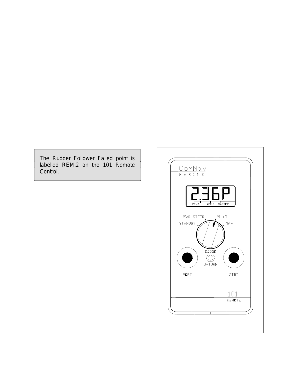
REMOTE CONTROLS
COMNAV 101 REMOTE CONTROL
This remote control plugs into the remote
receptacle on the rear of the autopilot.
Control is taken at the remote by pressing
both its pushbuttons for one second. The
command point on all LCD displays will
move to the REM.1 position.
A display, master select switch,
pushbuttons, and a DODGE/TURN toggle
switch are also included. Its operation is
identical to the operation of the autopilot
except for the toggle switch. All the points
on the display have the same meanings
as on the autopilot display.
PILOT position. The autopilot is now
steering the vessel on its current heading.
or
If the toggle switch was held in the
DODGE position while the master select
switch was rotated to PILOT, the autopilot
will steer the vessel back to its last course
.
The Rudder Follower Failed point is
labelled REM.2 on the 101 Remote
Control.
Place the master select switch in the
STANDBY position. To display the
currently selected type of special turn,
pull the toggle switch to the TURN
position and release it
To change the currently selected type of
special turn, press either the red or green
pushbutton.
Place the master select switch in the
POWER STEER position. To move the
rudder port or starboard, the red and
green pushbuttons can be used.
The vessel's rudder angle will be
displayed while the pushbutton is
pressed.
To recall the vessel's last course, hold the
toggle switch in the DODGE position and
then rotate the master select switch from
POWER STEER to PILOT.
Place the master select switch in the
Figure 10- 101 Remote Control
50
Page 54
To change the vessel's course by one
degree, press and release either the red
or green pushbutton.
To change the vessel’s course by 10
degrees per second, press and hold
either the red or green pushbutton. The
vessel will turn to the new heading at the
current Turn Rate setting. The vessel can
be dodged off course by holding the
toggle switch in the DODGE position and
pressing one of the pushbuttons. The
vessel's rudder angle will be displayed.
The rudder can be returned to the Dead
Ahead position, holding the vessel off
course, by holding the toggle switch in the
DODGE position without pressing either
pushbutton. Release the toggle switch
and the vessel will return to the
programmed course at the current Turn
Rate setting.
The currently selected type of special turn
can be started by pulling the toggle switch
to the TURN position, releasing it and
then pressing either the port or starboard
pushbutton. The direction of the special
turn is determined by which pushbutton is
used.
To interface the autopilot with a
navigation device, place the master select
switch in the NAV position.
To display the incoming data type and
cross track error sense, pull the toggle
switch to the TURN position and release
it.
To select either Normal or Reversed
response to cross track error, press the
green pushbutton.
The dodge function works as described
earlier, except that the vessel will return to
the track to the waypoint rather than the
programmed course after the dodge is
released.
The back of the remote provides two
key-hole slots which can be used to
either temporarily deposit or
permanently mount it on any suitable
location.
TO MOUNT THE REMOTE
PERMANENTLY:
Drill two holes for the mounting screws
3.5 in (9.0 cm) apart.
Drop the screws' heads into the
keyhole slots and then into the two
holes drilled. Fasten the screws with
washers and nuts from the back of the
mounting surface.
TO MAKE THE REMOTE
REMOVABLE FROM IT'S MOUNT.
Provide two #10 pan head stainless
steel screws (M5 cylinder head).
Place these 3 inches (7.6 cm) apart in
a suitable location, with a gap of 0.1
inches (2.5 mm) between the
underside of the screws' heads and
the mounting surface. Drop the remote
over the screws' heads and pull it
down to mount it. Lift it up to remove
the remote for hand-held operation.
SEE TABLE VI FOR HOOKUP
SPECIFICATIONS.
During the first year, check that the
glands are hand-tight every six
months and yearly thereafter.
51
Page 55
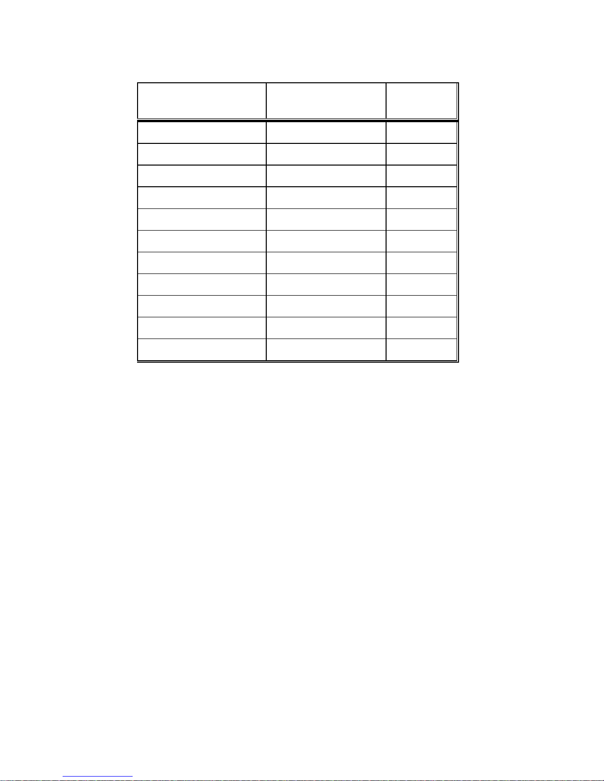
Table VI - 101 REMOTE Cable Connections
Wire Colour Terminal Number Plug Pin
Number
Shield 1 11
Pink 2 3
White 3 10
Brown 4 2
Violet 5 5
Grey 6 12
Green 7 9
Red 8 8
Yellow 9 7
Black 10 6
Blue 11 4
52
Page 56
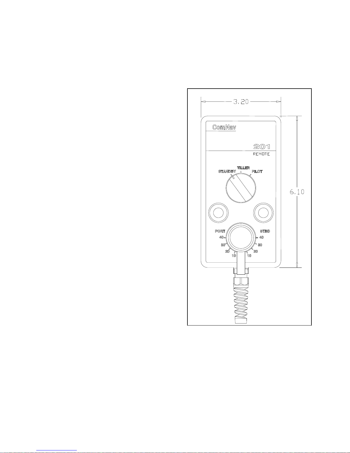
COMNAV 201 REMOTE CONTROL
This remote control plugs into the remote
receptacle on the rear of the autopilot.
Control is taken at the remote by pressing
both its pushbuttons for one second. The
decimal point on the 1001 Control Head
display will move to the REMOTE
position. The Standby mode is a safety
feature that allows the remote station to
de-activate the autopilot output to the
steering drive unit. When the switch is in
the TILLER position, the vessel's rudder
will be turned to the same angle as
indicated by the control knob.
To lock the vessel onto a heading under
autopilot control, point the vessel onto a
desired heading, and then place the
switch in the PILOT position. The
pushbuttons can be used to alter the
vessel's heading in one-degree steps, or
by 10 degrees per second after holding
the pushbutton for half a second.
Figure 11- 201 Remote Control
53
Page 57
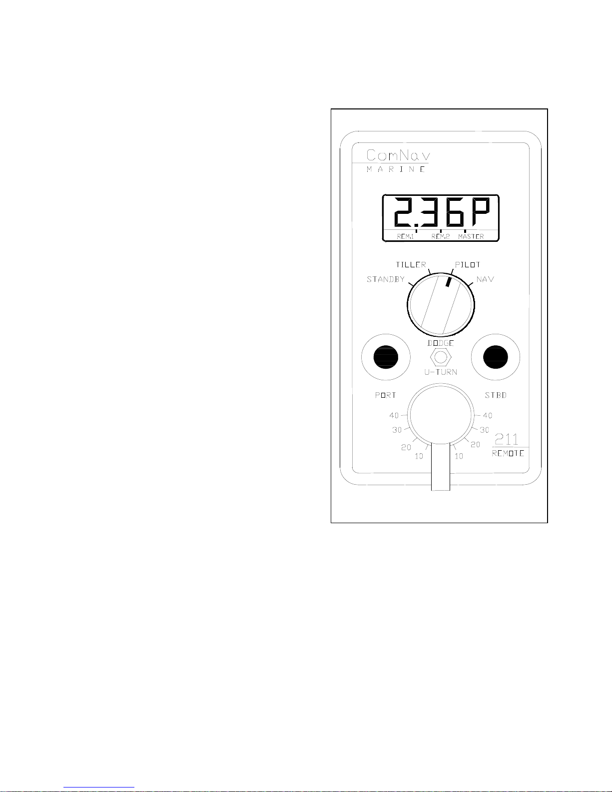
COMNAV 211 REMOTE CONTROL
This remote control plugs into the remote
receptacle on the rear of the autopilot.
Control is taken at the remote by pressing
both its pushbuttons for one second. The
decimal point on the 1001 Control Head
display will move to the REMOTE position
and the decimal point on the 211 Remote
display will move to REM.1.
The Standby mode is a safety feature
that allows the remote station to deactivate the autopilot output to the
steering drive unit. When the switch is in
the TILLER position, the vessel's rudder
will be turned to the same angle as
indicated by the control knob.
To lock the vessel onto a heading under
autopilot control, point the vessel onto a
desired heading, and then place the
switch in the PILOT position. The
pushbuttons can be used to alter the
vessel's heading in one-degree steps, or
by 10 degrees per second after holding
the pushbutton for half a second.
The DODGE/U-TURN toggle switch
operates identically to the COMNAV 101
remote.
Figure 12 - 211 Remote Control
54
Page 58
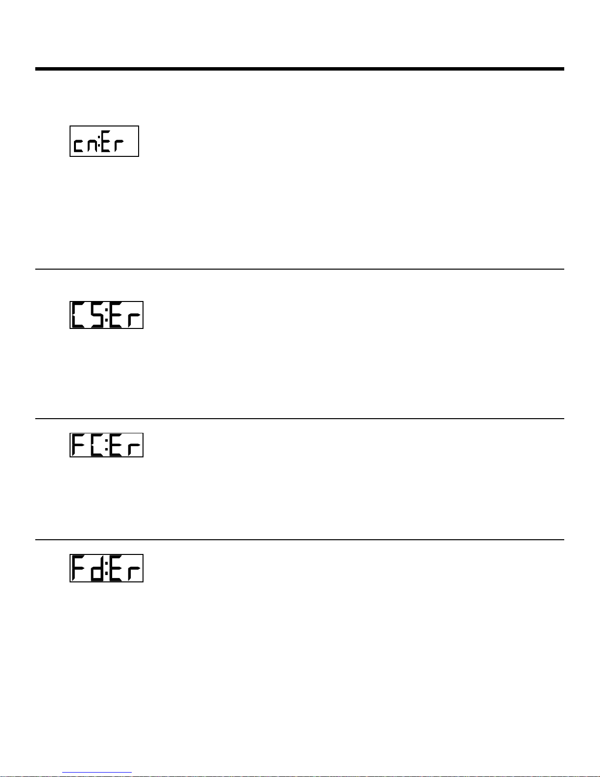
ERROR CHECKING
THE AUTOPILOT WILL DISPLAY AN ERROR MESSAGE AND SOUND THE ALARM
WHEN ANY OF THE FOLLOWING CONDITIONS EXIST:
The checksum in one of the RMA, RMB or RMC
CHECKSUM
ERROR
data sentences is set incorrectly or there is a
transmission problem between the navigation
device and the autopilot.
If you choose to continue using the interface, the checksum
evaluation can be turned off by rotating the master select
switch to STANDBY and pressing the ADJUST key until the
display shows 'cn:ON'. Press either the up or down ARROW
key until the display shows 'cn:OF'.
The vessel has fallen more than 20 degrees off
COURSE ERROR
course and has remained off course for more
than 30 seconds.
This indicates a possible failure of the rudder follower, or more
likely, the power steering system. Check for an inoperative
motor drive, blown breaker to the motor, jammed four-wayvalves, etc..
There is a problem with the circuitry inside the
FAULTY
COMPASS ERROR
autopilot associated with the compass
interface.
The autopilot is operable in non-autopilot modes only (i.e.
STANDBY or POWER STEER).
One or more of the alarm flags in the data
FAULTY DATA
FROM NAV
DEVICE ERROR
sentence from the Nav Device are set.
The autopilot will continue to use the data, but will sound the
alarm and display this error message after every data
sentence received until the error flags are cleared. Extreme
caution should be used if the autopilot is left in the NAV mode.
Check the front display of the Nav device for an alarm
message. If the alarm continues for more than 30 seconds,
disengage the autopilot.
55
Page 59
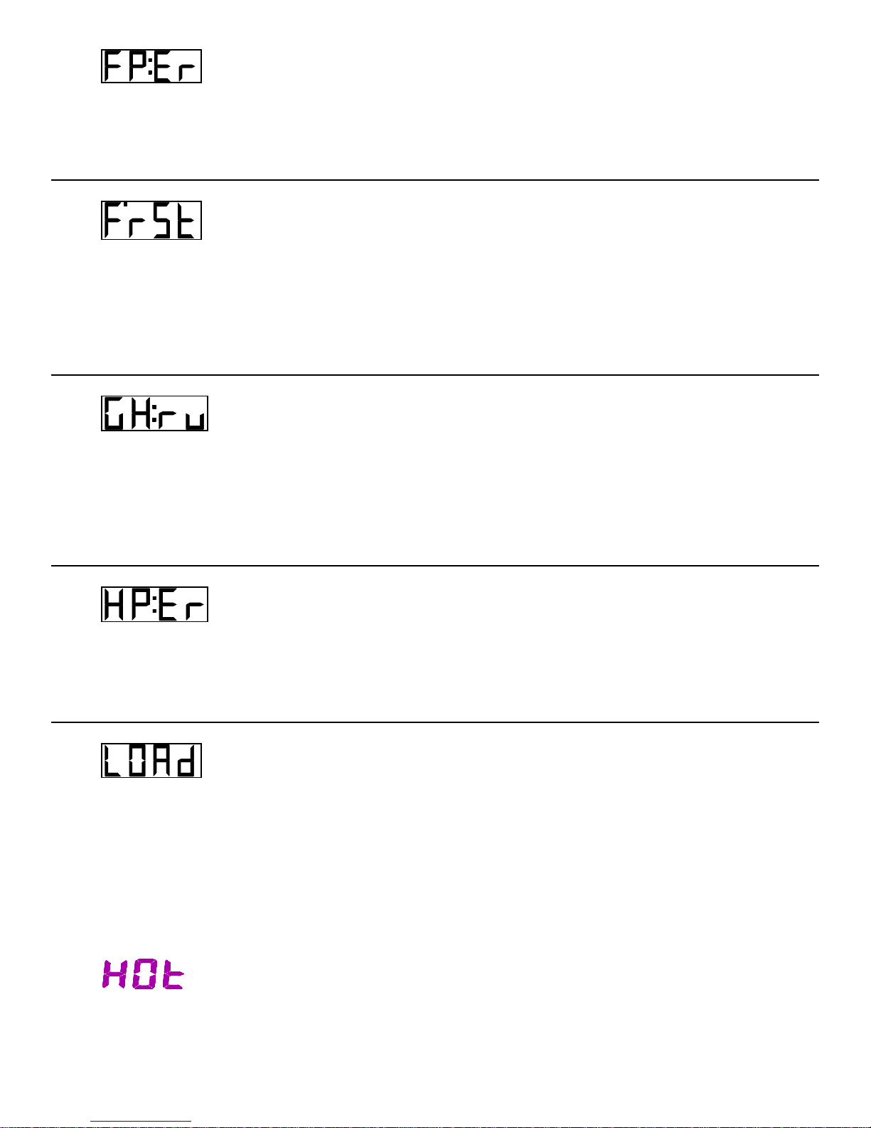
FRONT PANEL
ERROR
FULL RESET
GHOST RUDDER
ON
HIGH POWER
ERROR
MOTOR LOAD
ERROR
- or -
One or more of the keys on the front panel are
stuck in the closed position or a remote may
have a faulty pushbutton.
The autopilot or remote can be used by pressing ALARM
CLEAR, however, some functions may not work properly.
If the test of the permanent memory indicated
that one or more of the bytes of data stored
were not correct, a number of controls are reset
to pre-determined values.
Return the FAST and SLOW Rudder, Counter Rudder, Yaw
and Turn Rate settings to their previous values. Autopilot will
automatically start Dockside Set-up program after Full Reset.
If the rudder follower is defective the autopilot
will display this message each time it is
switched between POWER STEER and PILOT.
This will remind you that it is using the Ghost Rudder program.
The autopilot will not work as well with the Ghost Rudder as it
will with the Rudder Follower so the Rudder Follower should be
repaired or replaced as soon as possible.
The voltage into the autopilot has risen above
35 VDC and the autopilot may get damaged.
Open the breaker which supplies power to the autopilot,
determine the cause of the high voltage and rectify it. Check
the voltage regulator as it is the most likely problem.
Autopilot is being used with motor drive which feeds
its operating current & temperature back to the
autopilot (i.e. CT2 Drive Box), and levels exceed safe
margins for more than 4 seconds. LOAd shows while
in the PILOT or NAV modes. HOt shows while in the
STANDBY or POWER STEER modes.
Check for a jammed rudder, or similar problem which
would cause this to happen.
DRIVE BOX
OVERHEATED
56
Page 60
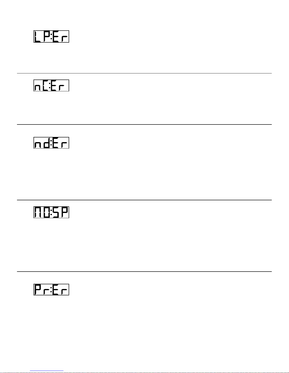
LOW POWER
ERROR
NO COMPASS DATA
ERROR
NO DATA FROM
NAV DEVICE ERROR
NO SPEED ERROR
PROM MEMORY
ERROR
The autopilot has detected that its input voltage has
dropped under 10 VDC.
Check for proper alternator operation, batteries low on water, or
some other condition that has caused the input voltage to drop.
The computer is not receiving any data from the
compass.
Check that the compass is plugged into the autopilot. The autopilot
is operable in non-autopilot modes only (i.e. STANDBY or POWER
STEER). Check that the autopilot is programmed for the correct
type of compass (see DOCKSIDE SETUP for information).
The autopilot is not receiving any recognizable data
from the Nav Device.
This could be because 1) the Nav Device is not programmed
correctly; 2) the Nav Device is not putting out any data; 3) there is a
problem with the cabling between the Nav Device and the autopilot
( i.e. broken or reversed wires); or 4) there is a fault with the
autopilot interface circuitry. Some Nav Devices will not put out a
data sentence for the autopilot until a waypoint has been entered,
and navigation towards it started.
The autopilot is in the PILOT or NAV mode, the speed
sensitive selection of the FAST or SLOW operating
modes is turned on and the autopilot is not receiving
any speed information from the navigation device.
Check that the device transmits one of the RMA, RMC, VBW, VHW
or VTG data sentences and that it is turned on. Check the cable
which connects the navigation device to the autopilot distribution
box, especially if you get a No Data error when the autopilot is in the
NAV mode.
The memory chip, which contains the autopilot
program, tested faulty.
The autopilot is not operable.
57
Page 61
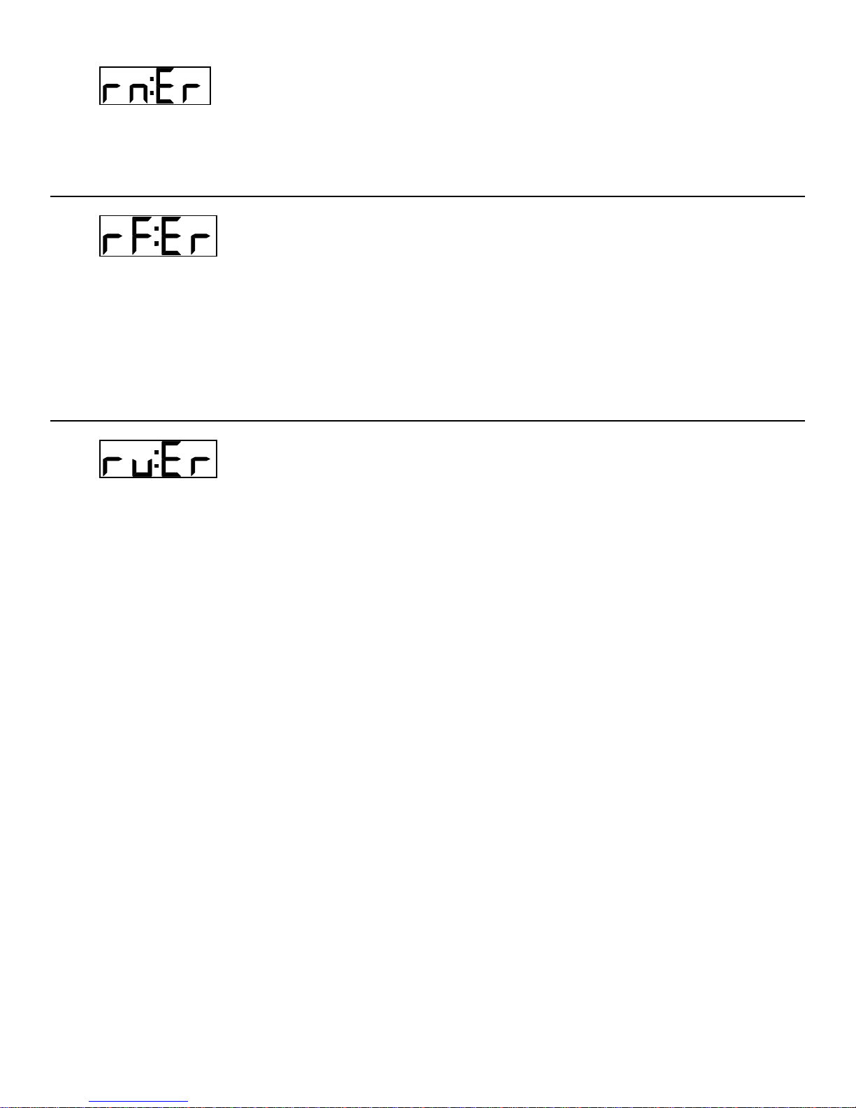
RAM MEMORY
ERROR
The portion of RAM memory used for temporary data
storage tested faulty.
The autopilot is not operable.
The autopilot has detected a problem with the rudder
RUDDER
FOLLOWER ERROR
follower.
Check for broken, disconnected or shorted wires, or a defective
rudder follower. The autopilot will switch to using the Ghost Rudder
program to control the rudder when the master select switch is in
the PILOT or NAV position. The digital and analog rudder angle
displays will not function in any mode. The RF:ER error message
will remain visible and the audible alarm will stay on until cleared.
Even though the alarm is cleared, the Rudder Follower "Failed
Point" on the display will remain visible.
The autopilot has failed to detect any movement by
RUDDER ERROR
the rudder in response to a command to move.
This error will only occur if the master select switch is in the PILOT
or NAV position.
Place the master select switch in the POWER STEER position and
measure how long it takes after pressing the red or green ARROW
key until the digital rudder angle reading begins to change,
particularly when the last rudder movement was in the other
direction.
If it takes longer than one second for the rudder to begin to move,
check for something which could cause a delay in the response of
the steering system such as air in the hydraulic steering or slack or
worn parts in the mechanical steering system.
Check for too low a setting of the Minimum Speed Potentiometer in
the CT1 Motor Drive Box (if one is used by the autopilot).
If the digital rudder angle display does not change, but the rudder is
definitely moving, check for a broken rudder follower linkage, or a
defective rudder follower.
If any of these alarm conditions occur, and cannot be easily rectified, return the autopilot to
an authorized service centre for servicing.
58
Page 62

Several different problems and possible solutions are outlined below. If the recommended
solution does not solve the problem, return the autopilot to an authorized service centre.
THE AUTOPILOT DOES
NOT TURN ON.
THE AUTOPILOT DOES
NOT TURN ON, BUT THE
ALARM SOUNDS
CONTINUOUSLY.
THE AUTOPILOT TURNS
ON, BUT DOES NOT TURN
THE RUDDER.
PROBLEM SOLVING
Check for power reaching the distribution box.
Check the main fuse or breaker panel.
Check that the main interconnect cable is properly plugged
into the rear of the autopilot.
Check the fuse in the autopilot distribution box. If it is blown,
replace it with a 5 X 20 mm 3.15 amp fuse. One spare fuse
of this value has been taped to the underside of the autopilot
distribution box lid. Make sure the power leads are not
reversed before using the spare fuse.
Check for a short circuit between +5V and ground.
Disconnect all leads in the distribution box except PILOT
PWR (+) and PILOT PWR (-). If this solves the problem,
then reconnect one set of leads at a time until the problem
re-occurs. The problem lies with the cabling to that external
device, or the external device itself (i.e. a drive box, the
rudder follower, a remote heading display, etc.).
If the problem does not disappear after disconnecting all the
leads, then there is something wrong with the autopilot.
Return it to the factory or an authorized service centre for
servicing.
Press the red and green ARROW key when the autopilot is
in the POWER STEER mode. The red and green PORT and
STBD LED's should come on in the distribution box. If all is
correct the problem is not in the autopilot.
Check for a fault in the power steering system (i.e. blown
breaker or fuse in electric system, broken drive belt or
jammed four way valve, etc.).
Check for a possible short in the output cable to the rudder
drive. (continued next page)
59
Page 63

THE AUTOPILOT TURNS
ON, BUT DOES NOT TURN
THE RUDDER. (continued
from page 56)
THE RUDDER TURNS
HARD OVER TO ONE SIDE.
THE AUTOPILOT TURNS
ON, BUT DOES NOT
OPERATE PROPERLY.
THE DISPLAYED COMPASS
HEADING DOES NOT
FOLLOW THE ACTUAL
COMPASS HEADING
PROPERLY.
THE AUTOPILOT STEERS
NORMALLY ON SOME
COURSES, BUT NOT ON
OTHERS, PARTICULARLY
NORTH OR SOUTH.
Check for full output voltage on the SWITCHED PWR line
with autopilot in the POWER STEER mode. The yellow SWI
POWER LED in the distribution box should come on when
the master select switch on the autopilot is in the POWER
STEER or higher mode.
Check that the voltage on the PORT OUT and STBD OUT
lines drop to less than 1.5 volts when their respective keys
are pressed.
Check the rudder drive for correct operation. For a 12 volt 4way valve, the common line from the solenoids must be
connected to UNSWITCH.PWR (terminal 3 in the
distribution box), rather than to SWITCHED.PWR.
Check the rudder follower for correct operation.
Check the rudder drive for correct operation (i.e. sticking
relays, sticking solenoid valves, etc.).
If the rudder appears to move normally with the autopilot in
POWER STEER, but goes hard over with the autopilot in
PILOT, recheck the rudder follower and rudder drive
connections in the distribution box for correct hook-up.
Perform the dockside set-up again.
Turn the master select switch to OFF and then to STANDBY
to restart the computer program.
Check the voltage in the distribution box for a minimum of
10.0 VDC between PILOT PWR and PILOT COM.
Check for problems in the cables leading to the optional
remote controls by unplugging them from the rear of the
autopilot.
Check for any compensating magnets, particularly heeling
magnets that are placed too close to the fluxgate sensor.
Check for any magnetic material such as tools, tin cans,
etc., near the compass, or directly underneath it, perhaps in
a drawer or cabinet.
The problem most likely lies with poor compass adjustment.
Contact a compass adjuster to have the compass
compensated for deviation, including that caused by heeling
error. Proper compass adjustment is particularly important
on steel-hulled vessels. Do not attempt to move any
compensating magnets yourself, as this may make the
compass dangerously inaccurate, particularly if it is used as
a steering compass.
60
Page 64

THE AUTOPILOT STEERS
POORLY ON ALL
COURSES.
THE REMOTE CONTROL
DOES NOT WORK AT ALL.
THE RUDDER DOES NOT
ALWAYS MOVE EVEN
THOUGH THE PORT OR
STARBOARD OUTPUT LED
IS LIT ON THE AUTOPILOT
FRONT PANEL AND THE
AUTOPILOT IS USING A
CT1 DRIVE BOX.
THE RUDDER LIMITS DO
NOT SEEM TO BE
CORRECTLY SET AND THE
AUTOPILOT IS USING A
CT2 DRIVE BOX.
Watch the card on the autopilot compass to make sure that
it follows the vessel’s movements properly. If the card
seems to turn with the vessel for a few degrees, and then
come free, either the pivot or jewel in the compass may be
defective.
Check the 'Remote in Command' point to see if the remote
is in control.
Check very carefully that the wires are inserted into the
terminal block in the remote control in the correct order, and
not in reversed order.
Recheck all the connections between the autopilot and the
drive box, making sure that none are interchanged.
Remove the cover of the CT1 Motor Drive Box and check
the setting of the minimum speed potentiometer for too low
a minimum speed.
Make sure that there is NO connection between the COM
terminal in the Drive Box and any terminal in the autopilot
Distribution Box.
61
Page 65

CE COMPLIANCE
This product has been tested and is in compliance with the Electro-Magnetic Compatibility (EMC)
standards of the European Community and bears the CE label. It has been tested according to the
applicable sections outlined under;
Technical standard #IEC945/EN60945
Marine Navigational Equipment
General Requirements
Applicable sections for methods of testing and required test results are;
Section 4.5.4: Radiated interference
Section 4.5.4: Immunity to electro-Magnetic Environment
Annex A, Section A.3: Immunity to conducted audio frequencies
Annex A, Section A.4: Immunity to earth lead coupling
Annex A, Section A.5: Immunity to conducted radio frequencies
Annex A, Section A.6: Immunity to radiated interference
Test results and a declaration of conformity are on file at the ComNav plant;
ComNav Marine Ltd
#15 - 13511 Crestwood Place
Richmond, BC, V6V 2G1, Canada
62
Page 66

LIMITED WARRANTY AGREEMENT
Congratulations, you have purchased sophisticated and sensitive marine navigation equipment (the "Equipment")
manufactured by ComNav Marine Ltd of #15 - 13511 Crestwood Place, Richmond, British Columbia, Canada, V6V 2G1
("ComNav").
LIMITED ONE YEAR WARRANTY. ComNav warrants to the Purchaser, provided that the recommended
installation and maintenance procedures set forth in the manual that has been provided with the Equipment (the
"Manual") have been followed, and subject always to the other provisions of this Agreement, that the Equipment is free
from defects in workmanship and materials under normal use and service and will perform substantially in accordance
with the specifications set forth in the Manual for a period of one (1) year from the date of purchase of the Equipment by
the Purchaser.
EXTENDED THREE YEAR LIMITED WARRANTY. If;
(a) the Equipment is installed:
(i) by an authorized ComNav Dealer; or
(ii) by someone other than an authorized ComNav Dealer, and such installation has been
inspected by an Authorized ComNav Dealer; and
(b) the Limited Warranty Registration Card has been returned to ComNav within 14 days of the date of purchase
of the Equipment by the Purchaser with Part I thereof having been completed by the Purchaser, and with the Extended
Limited Warranty Card having been completed and signed by an authorized ComNav Dealer and returned to ComNav
within 14 days of that inspection;
ComNav warrants to the Purchaser that the Equipment is free from defects in workmanship and materials under normal
use and service and will perform substantially in accordance with the specifications set forth in the Manual for a period
of three (3) years from the date of purchase of the Equipment, subject always to the other provisions of this Agreement.
NO OTHER WARRANTIES. TO THE MAXIMUM EXTENT PERMITTED BY APPLICABLE LAW, COMNAV
DISCLAIMS ALL OTHER WARRANTIES AND CONDITIONS, EITHER EXPRESS OR IMPLIED, STATUTORY OR
OTHERWISE WITH RESPECT TO THE EQUIPMENT, INCLUDING BUT NOT LIMITED TO IMPLIED WARRANTIES
OR CONDITIONS OF MERCHANTABILITY AND FITNESS FOR THE ORDINARY PURPOSES FOR WHICH THE
EQUIPMENT IS USED OR FITNESS FOR A PARTICULAR PURPOSE AND ANY OTHER OBLIGATIONS ON THE
PART OF COMNAV, ITS EMPLOYEES, SUPPLIERS, AGENTS, OR REPRESENTATIVES.
NO LIABILITY FOR CONSEQUENTIAL DAMAGES. TO THE MAXIMUM EXTENT PERMITTED BY
APPLICABLE LAW, IN NO EVENT SHALL COMNAV, ITS EMPLOYEES, SUPPLIERS, OR REPRESENTATIVES BE
LIABLE FOR ANY DAMAGES WHATSOEVER, INCLUDING WITHOUT LIMITATION DAMAGE FROM COLLISION
WITH OTHER VESSELS OR OBJECTS, INJURY TO ANY PERSON OR PERSONS, DAMAGE TO PROPERTY,
LOSS OF INCOME OR PROFIT, BUSINESS INTERRUPTION, OR ANY OTHER CONSEQUENTIAL, INCIDENTAL,
RESULTING PUNITIVE, OR SPECIAL DAMAGES ARISING OUT OF THE USE OF OR INABILITY TO USE THE
EQUIPMENT, INCLUDING THE POSSIBLE FAILURE OR MALFUNCTION OF, OR DEFECTS IN THE EQUIPMENT,
OR ANY PART THEREOF, EVEN IF COMNAV HAS BEEN ADVISED OF THE POSSIBILITY OF SUCH DAMAGES.
SOME STATE/JURISDICTIONS DO NOT ALLOW THE EXCLUSION OR LIMITATION OF CONSEQUENTIAL OR
INCIDENTAL DAMAGES, SO THE ABOVE LIMITATION MAY NOT APPLY TO THE PURCHASER.
REMEDIES NOT TRANSFERABLE. The Purchaser's remedies under this Agreement only apply to the original
end-user of the ComNav Equipment, being the Purchaser, and only apply to the original installation of the Equipment.
The Purchaser's remedies under this Agreement are not transferable or assignable by the Purchaser to others in whole
or in part.
63
Page 67

NOTICE OF DEFECT. The Limited Warranty and the Extended Limited Warranty will not apply with respect to any
defective Equipment unless written notice of such defect is given to ComNav, by mail to the address for ComNav set
forth above, or by facsimile to ComNav at 1-604-207-8008, and is received by ComNav within ten (10) days of the date
upon which the defect first became known to the Purchaser. Notices sent by mail will be deemed to be received by
ComNav on the seventh (7th) day first following the date of posting in North America and on the tenth (10th) day next
following the date of posting anywhere else in the world. Notices sent by facsimile will be deemed to be received by
ComNav on the date of transmission with appropriate answerback confirmation.
WARRANTY LIMITATIONS. Reversing Pumps & Motors, Hydraulic Linear Actuators, Watch Alarms & Motor
Control Boxes which may comprise part of the Equipment are warranted by ComNav for a period of two (2) years under
the Extended Limited Warranty described above. All Remote Controls, Remote Cables, Jog Switches, Analog meters
(rudder angle indicators), Rudder Angle Indicator Systems & Accessories, Magnetic Compasses & Accessories,
Constant Running Pumps, Engine Driven Pumps, Hydraulic Manifolds & Hydraulic Steering are warranted by ComNav
for a period of one (1) year under the Limited Warranty described above.
IMPLIED WARRANTIES. Any implied warranties with respect to the Equipment are limited to one (1) year.
Some states/jurisdictions do not allow limitations on how long an implied warranty lasts, so the above
limitation may not apply to the Purchaser.
CUSTOMER REMEDIES. ComNav's entire liability and the Purchaser's exclusive remedy against ComNav for the
defective Equipment shall be, at ComNav's option, either: (a) repair or replacement of the defective Equipment under
the warranties set forth in this Agreement, or, (b) refund of the purchase price of the defective Equipment, all pursuant
to and in accordance with the conditions set out below:
1. If the Equipment, or any part thereof, proves to be defective within the relevant warranty period, the Purchaser
shall do the following:
(a) contact ComNav by phoning 1-604-207-1600 to discuss the nature of the problem and obtain shipping
instructions (many times a satisfactory solution can be reached without returning the item); and
(b) prepare a detailed written statement of the nature of and circumstances of the defect, to the best of
the Purchaser's knowledge, including the date of purchase of the Equipment, the place of purchase,
the name and address of the installer, and the Purchaser's name , address and telephone number to
be sent, along with proof of purchase, to ComNav;
2. If upon examination by either ComNav or by an Authorized ComNav Dealer, the defect is determined to result
from defective workmanship or material and if the defect has occurred within the relevant warranty period set
forth above, the Equipment or the defective parts thereof will be repaired or replaced, at ComNav's sole option,
without charge, and shall be returned to the Purchaser at ComNav's expense. Return delivery will be by the
most economical means. Should the Purchaser require the Equipment to be returned by a faster method, the
costs incurred by expedited delivery will be pre-paid by the Purchaser;
3. No refund of the purchase price for the Equipment will be made to the Purchaser unless ComNav is unable to
remedy the defect after having a reasonable number of opportunities to do so. Prior to refund of the purchase price, the
Purchaser must submit a statement in writing from an Authorized ComNav Dealer that the installation instructions in the
Manual have been complied with in full and that the defect remains;
4. Warranty service shall be performed only by ComNav or by an Authorized ComNav Dealer. Any attempt to
remedy the defect by anyone else shall render the warranties set forth in this Agreement void;
5. Charges for overtime, stand-by, holiday and per diem will not be paid by ComNav and are specifically excluded
from the warranties set forth in this Agreement. ComNav may, under special circumstances, and with
ComNav's PRIOR approval, pay ONE TIME travel costs. Any cost of ferry, boat hire, or other special means of
transportation must have prior approval from ComNav. ComNav reserves the right to refuse service charges in
excess of one hour if the technician has not contacted ComNav's service department for assistance. Travel
cost allowance to service certain Equipment with a suggested retail price of below $2,500.00 (Canadian funds
or equivalent) is not authorized. If repairs are necessary, these products must be forwarded to ComNav or an
Authorized ComNav Dealer at Purchaser's expenses and will be returned as set out in CUSTOMER
REMEDIES, Item 2;
64
Page 68

6. There shall be no warranty for defects in, or damages to, the Equipment caused by:
(a) faulty installation or hook-up of the Equipment;
(b) abuse, misuse or use of the Equipment in violation of the instructions set forth in the Manual;
(c) shipping, alterations, incorrect and/or unauthorized service;
(d) accident, exposure of the Equipment to excessive heat, fire, lightning, salt or fresh water
spray, or water immersion except for Equipment specifically designed as, and stated in the
Manual to be, waterproof. Water damage to the Equipment due to failure to cover unused
receptacles is specifically excluded from any warranty set forth in this Agreement; and
(e) improper or inadequate ancillary or connected equipment;
7. This warranty does not cover routine system checkouts, alignment, or calibration unless the service has been
authorized in writing by ComNav PRIOR to its commencement; and
8. No Equipment shall be repaired or replaced under warranty if the serial number of that Equipment has been
removed, altered or mutilated.
CHOICE OF LAW AND JURISDICTION. This Agreement is governed by the laws of the Province of British
Columbia, Canada. If you acquired the Equipment outside of Canada, each of the parties hereto irrevocably attorn to
the jurisdiction of the courts of the Province of British Columbia, Canada and further agree to settle any dispute,
controversy or claim arising out of or relating to this Limited Warranty, or the breach, termination, or invalidity of it, by
arbitration under the rules of the British Columbia International Commercial Arbitration Centre ("BCICAC"). The
appointing authority shall be BCICAC [or, if the BCICAC shall cease to exist, the Chief Justice of the Supreme Court of
British Columbia]. BCICAC shall administer the case in accordance with BCICAC Rules. There shall be one arbitrator
and the place of arbitration shall be Vancouver, British Columbia.
The United Nations Convention on Contracts for the International Sale of Goods Act, S.B.C. 1990, c. 20, and any other
statutory enactments of the United Nations Convention on Contracts for the International Sales of Goods do not apply to
this Agreement.
THIS LIMITED WARRANTY GIVES THE PURCHASER SPECIFIC LEGAL RIGHTS. THE PURCHASER MAY ALSO
HAVE OTHERS WHICH VARY FROM STATE/JURISDICTION TO STATE/JURISDICTION.
This Agreement is a legal contract between you (the "Purchaser") and ComNav. By retaining the Equipment for more
than thirty (30) days and/or installing and/or using the Equipment, the Purchaser agrees to be bound by the terms of this
Agreement. If the Purchaser does not agree to be bound by the terms of this Agreement, the Purchaser may return the
Equipment in the same condition in which it was received for a full refund (less shipping and handling costs) within thirty
(30) days of purchase.
WARNING
A qualified person should always be in a position to monitor the vessel's heading, watch for navigational hazards and
should be prepared to revert to manual steering immediately if an undesired change of heading occurs, if the heading is
not maintained within reasonable limits, or when navigating in a hazardous situation.
. The Equipment is an aid to navigation only. It is not intended or designed to replace the person on watch.
ALWAYS REMEMBER:
WHENEVER UNDER WAY, A QUALIFIED PERSON ON WATCH IS REQUIRED BY LAW
.
65
Page 69

MANUAL PUBLISHED BY:
COMNAV MARINE LTD
#15 - 13511 Crestwood Place
Richmond, BC
CANADA V6V 2G1
TELEPHONE: 604-207-1600
FACSIMILE: 604-207-8008
E-MAIL: [email protected]
WEB SITE: www.comnavmarine.com
TOLL FREE IN CANADA OR THE USA;
PHONE: 1-800-428-0212
FAX: 1-800-470-9611
THE 1001 AUTOPILOT SYSTEM COMPLIES
WITH ALL RELEVANT CE REGULATIONS
FIRST PRINTING DECEMBER 1990
REVISED December 1998
66
Page 70

MANUAL CHANGES
DECEMBER 27, 1996
1) PAGE 31 - A STERNER, MORE DETAILED WARNING WAS GIVEN REGARDING
RESIDUAL AIR AS WELL LEAKING FITTINGS AND EQUIPMENT.
2) PAGE 15 - WARNING ADDED ABOUT ATTAINING A 10 TO 15 SECOND H.O. TIME.
FEBRUARY 12, 1997 - CE CERTIFICATION DETAILS ADDED
MARCH 17, 1997
PAGES 5, 6 & 7 - NEW WARRANTY POLICY
December 14, 1998
Converted to Word. Removed all 1001M information & W/F references
April 28, 1999
Removed all old drawing and replaced with new KVH Gyro Trac drawing.
August 29, 2000
Change ComNav's address.
67
 Loading...