

Page 1
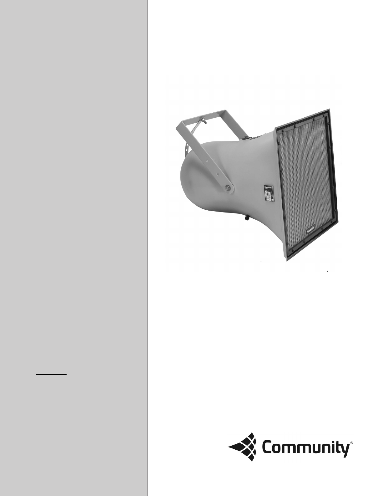
R SERIES
R1
Owner’s Manual
Weather-Resistant, High-Fidelity,
Full-Range Loudspeaker Systems
Models
R1-64z
R1-66z
R1-94z
Page 2

EC STATEMENT OF CONFORMITY
This document confirms that the range of products of Community Professional Loudspeakers bearing the CE
label meets all of the requirements in the EMC directive 89/336/EEC laid down by the Member States Council
for adjustment of legal requirements. Furthermore, the products comply with the rules and regulations
referring to the electromagnetic compatibility of devices from 30-August-1995.
The Community Professional Loudspeaker products bearing the CE label comply with the following
harmonized or national standards:
DIN EN 55013:08-1991
DIN EN 55020:05-1995
DIN EN 55082-1:03-1993
The authorized declaration and compatibility certification resides with the manufacturer and can be viewed
upon request. The responsible manufacturer is the company:
Community Light & Sound
333 East Fifth Street
Chester, PA 19013
USA
TEL: (610) 876-3400
FAX: (610) 874-0190
FIND THE LATEST ONLINE
Every effort has been made to insure that the information contained in this manual was complete
and accurate at the time of printing. However, due to ongoing technical advances, changes or
modifications may have occurred that are not covered in this publication. The latest version of this
manual and the most recent product information published by Community is always available at
http://www.communitypro.com. The publication date can be found on the rear cover or last page.
© 2015 Community Professional Loudspeakers page 2
Page 3

COMMUNITY PROFESSIONAL LOUDSPEAKERS
A TRADITION OF EXCELLENCE AND INNOVATION
Since the founding of our company in 1968, Community has been a constant developer and innovator
of loudspeaker technology. Many of our engineering achievements were undertaken to solve
problems, when no prior solutions existed. Others resulted from simply seeing a better way to do
things.
Over the years our technologies have been imitated, and our methods have become common
practice throughout the professional sound industry. However, developments like carbon fiber
diaphragm compression drivers still stand alone, and well ahead of the competition. Just a few of
Community’s unique accomplishments include the following:
· First successful fiberglass mid, high frequency, and large-format bass horns.
· First compression loaded mid-range horn for touring systems - the LMF.
· First suspension-less diaphragm HF driver - the VHF100.
· First mid-range, full-decade (200 Hz - 2 kHz) high-power compression driver - the M4.
· First carbon fiber diaphragm compression drivers - M4, EM280, EM282.
· First Ferrofluid-cooled professional woofers - the VBS Series.
· First product series with all drivers Ferrofluid-cooled.
· First air-cooled loudspeakers for touring systems - AirForce.
· First three-way cinema loudspeaker systems - Paramount Executive Studio Theatre, Warner Bros.
screening theatre and dubbing rooms.
· First electro-acoustic system to equal the sound level of pneumatic warning sirens.
· First to provide loudspeaker coverage over an entire country - Denmark Emergency System.
· First comprehensive, calibrated data acquisition of sound reinforcement products.
· First integral signal-aligned three-way sound reinforcement systems - RS Series.
· First pro audio company with an Internet Web site.
· First all horn-loaded, high-fidelity, weather-resistant loudspeaker - R2 Series.
In line with our history of excellence and innovation, each Community product is manufactured in
accordance with a complicated and exacting chain of procedures that ensure absolute quality.
With our unique designs, our sophisticated techniques, and our proprietary materials and
transducers, we are committed to bringing only the finest audio products to the many thousands of
professional sound engineers, performers, and end users who rely on them daily.
Community Professional Loudspeakers
333 East Fifth Street
Chester, PA 19013-4511 USA
TEL: (610) 876-3400 FAX: (610) 874-0190
www.communitypro.com © 2015 All Rights Reserved
© 2015 Community Professional Loudspeakers page 3
Page 4

© 2015 Community Professional Loudspeakers page 4
Page 5

TABLE OF CONTENTS
CHAPTER PAGE
EC Statement of Conformity ........................................................................................................................................ 2
Community Professional Loudspeakers ................................................................................................................. 3
1. Important Safety Information .................................................................................................................. 6
2. Introduction to Weather-Resistant Loudspeakers .......................................................................... 7
3. Unpacking and Inspection .......................................................................................................................... 8
Quick Start...................................................................................................................................................... 9
4. Physical Features .......................................................................................................................................... 10
5. General Description ...................................................................................................................................... 11
5.8 Coverage Patterns ......................................................................................................................................... 12
6. Choosing Power Amplification ................................................................................................................. 12
7. Electrical Installation ................................................................................................................................... 13
7.1 Connecting the Loudspeaker ................................................................................................................... 13
8. Physical Installation ..................................................................................................................................... 14
8.2 Orienting an R1 ................................................................................................................................................ 15
8.2.1 Throw Distance and Operating Levels .................................................................................................. 16
8.3 Installing the R1 Yoke ................................................................................................................................... 17
8.4 Weather Resistance and Maintaining Weather Resistance ......................................................... 19
8.4.2 Mechanical Installation and Safety ........................................................................................................ 19
9. Operating Precautions ................................................................................................................................. 20
10. Servicing ............................................................................................................................................................ 20
11. Technical Specifications ............................................................................................................................. 22
12. In Case of Difficulty ....................................................................................................................................... 23
13. Warranty Information .................................................................................................................................. 24
Notes .............................................................................................................................................................................. 27
FIGURES and TABLES PAGE
Quick Start ........................................................................................................................................................................ 9
Fig 1: Physical Features .......................................................................................................................................... 10
Fig 2: R1 Mounting Point Detail............................................................................................................................. 13
Fig 3: R SERIES Operating Distances .................................................................................................................. 16
Fig 4: R1 Yoke Assembly .......................................................................................................................................... 17
Fig 5: R1 Wiring ........................................................................................................................................................... 21
Fig 6: R1 Yoke ............................................................................................................................................................... 26
Table 1: Wire Gauge Selection ................................................................................................................................... 13
Table 2: Replacement Parts........................................................................................................................................ 21
© 2015 Community Professional Loudspeakers page 5
Page 6

R SERIES - R1 OWNER’S MANUAL
1. IMPORTANT SAFETY INFORMATION
Always follow these basic safety precautions when using or installing R SERIES loudspeakers and accessories:
Read these instructions.
Keep these instructions.
Heed all warnings.
Follow all instructions, particularly those pertaining to rigging, mounting, hanging and electrical connections.
Only use accessories that are specified and approved by the manufacturer.
The terms IMPORTANT, WARNING, and DANGER are used throughout this manual to alert the reader to
important safety considerations. If you have any questions or do not understand the meaning of these terms,
do not proceed with installation. Contact your local dealer, distributor, or call Community directly for
assistance. These terms are defined below:
IMPORTANT: describes an operating condition or user action that may expose the equipment or
user to potential damage or danger.
WARNING: describes an operating condition or user action that will likely cause damage to the
equipment or injury to the user or to others in the vicinity.
DANGER: describes an operating condition or user action that will immediately damage the
equipment and/or be extremely dangerous or life threatening to the user or to others in the
vicinity.
1.1 RIGGING AND ELECTRICAL SAFETY
DANGER: The loudspeakers described in this manual are designed and intended to be ‘flown’ or
mounted or suspended for maximum acoustical performance using a variety of rigging hardware,
means, and methods. Installation of loudspeakers should only be performed by trained and
qualified personnel. It is strongly recommended that a licensed and certified professional
structural engineer approve the mounting design. Severe injury and/or loss of life may occur if
these products are improperly installed.
DANGER: R SERIES rigging fittings are rated at a Working Load Limit (WLL) of 100 lbs (45.4kg) with
a 10:1 safety margin. No single rigging fitting should ever be subjected to a load that is greater
than this stated limit. Failure to heed this warning could result in severe injury and/or loss of life.
IMPORTANT: Refer to the sections on installation and connections later in this manual for
additional information on rigging and electrical safety.
IMPORTANT: The stainless steel mounting bolts that come installed in each enclosure must either
be used to mount the Accessory Mounting Yoke or they must be kept in place to seal the enclosure
from air leaks. If the rigging fittings do not remain sealed, air leaks will occur in the enclosure that
will compromise the loudspeaker’s weather-resistance and its low frequency performance.
© 2015 Community Professional Loudspeakers page 6
Page 7

2. INTRODUCTION OF R SERIES
Introduction
Community’s R SERIES is a high-quality, high-fidelity product line designed to be highly weather-resistant.
R SERIES products perform consistently in continuous outdoor exposure while simultaneously providing
superlative acoustic performance.
This manual is intended to help you install and use R SERIES loudspeakers safely and effectively. It provides
useful information to help you obtain the best performance, sound quality, and reliability from your R SERIES
systems. We’ve provided Quick-Start diagrams to enable you to install and operate the products immediately.
However, we recommend that you read this manual in its entirety, to ensure that your R SERIES installation
meets the highest possible standards.
While every attempt has been made to ensure this information is correct and up-to-date, Community
continuously incorporates worthwhile improvements to each product which may include changes and/or
modifications not contained in this manual.
2.1 DESCRIPTION OF R SERIES
All-Weather, All-Purpose
Though designed to handle the harshest environmental conditions, R SERIES is the perfect choice for many
indoor environments. With 22 models to choose from, ranging from short throw with wide coverage angles to
ultra-narrow, long throw systems, the task of designing an acoustically and economically effective sound
system has never been easier. In many cases, a small number of R SERIES loudspeakers can provide top
quality sound for a surprisingly large physical area, making them one of the most acoustically and
economically effective solutions available anywhere. Visit www.communitypro.com to learn more about the
entire R SERIES family including R6, R-MAX, R2, R1, R.5, R.35, R.25, R.15, RSH and RMG systems.
R SERIES Applications
R SERIES products are designed for permanent installation or portable use both outdoors and indoors. The
primary applications for Community’s R SERIES are those where re-entrant horns, outdoor two-way
horn/woofer loudspeakers, and some larger horn loudspeakers typically are used but lack capability for both
high quality music reproduction and longer distance voice projection.
R SERIES products are ideally suited for athletic fields (football, soccer, baseball, tennis) and field houses,
theme parks, amusement parks, swimming pools, ski slopes, cruise ships, steeple carillons, fairgrounds,
rodeos, small arenas, racing tracks, air shows, skating rinks, convention centers, factories, warehouses, and
portable sound systems. They can complement Community WET Series products for projects needing a
combination of both longer and shorter-throw applications.
© 2015 Community Professional Loudspeakers page 7
Page 8

3 UNPACKING AND INSPECTION
Unpacking and Inspection
R SERIES loudspeakers are inherently rugged and are carefully packed in sturdy cartons. However, it’s wise to
thoroughly inspect each unit after it has been removed from the packaging, as damage could occur during
shipping.
Shipping Claims
Please note that once the shipment has left your dealer or the Community factory, the responsibility for
damage is always borne by the freight company. If damage has occurred during shipping, you must file a claim
directly with the freight company. It’s very important to contact the freight company as soon as possible after
receiving your shipment, as most freight companies have a short time limit within which they will investigate
claims. Make sure to save the carton and the packing material, as most claims will be denied if these materials
are not retained. Your Community dealer and the factory will try to help in any way they can, but it is the
responsibility of the party receiving the shipment to file the damage claim.
It’s always a good idea to retain the carton and packing materials indefinitely, if possible, in the event that the
unit may need to be returned to your dealer or distributor for repair in the future
What Is In the Box
Each shipping carton contains the following items:
(1) R1 Full-Range Loudspeaker System
.
1/2—13 x 1” stainless steel mounting bolts, each with a lock, flat, and rubber washer (already installed
on the enclosure)
Mounting Yoke (Qty 1)
Installation/Operation Manual (Qty 1)
Warranty Card (Qty 1)
© 2015 Community Professional Loudspeakers page 8
Page 9
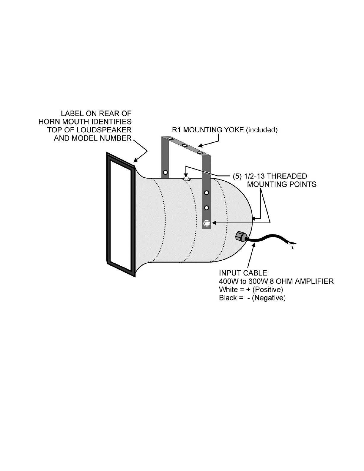
QUICK START
© 2015 Community Professional Loudspeakers page 9
Page 10
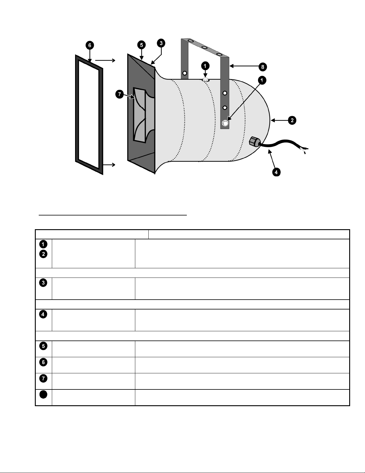
FIGURE 1: Physical Features
4 PHYSICAL FEATURES (See FIGURE 1)
MOUNTING / RIGGING POINTS DESCRIPTION
MOUNTING / RIGGING
POINTS
OTHER MOUNTING POINTS
GRILLE RETAINERS
INPUT
INPUT CABLE For signal connections to the loudspeaker. About 4 feet of 16-2 SJOW
OTHER FEATURES
R1 LABEL Model number, coverage pattern, serial number, hook-up, and power
GRILLE Perforated steel backed by a layer of UV-resistant reticulated foam and
HIGH FREQUENCY HORN
ASSEMBLY
MOUNTING YOKE The R1 mounting yoke is included in the carton.
8
Five, 4 on around the sides and 1 on rear. 1/2-13 captive zinc plated inserts
with 1/2-13 x 1-1/4 in. SS bolts, lock, flat, and rubber washers. Used for
attaching the R1 YOKE mounting bracket or customer-supplied mounting
system.
The grille assembly is retained by 16 #6 self-tapping SS Phillips-head screws.
Four screw from the rear of the horn mouth into a channel in the extruded
aluminum grille frame.
retained by a factory-sealed gland-nut.
White = + and Black = –.
information. Also used to identify the top of the horn enclosure.
woven polyester mesh. (A grille is not supplied with BNG models.)
Mounted inside bass horn to form a co-axial system.
1
1 Top of enclosure is up for specified horizontal and vertical coverage.
© 2015 Community Professional Loudspeakers page 10
Page 11

5 GENERAL DESCRIPTION
The Community R1 loudspeakers are two-way, coaxial, full-range systems. Completely horn-loaded and with
an enclosure constructed of fiberglass, they are highly weather-resistant, easy to install, and produce very
high output for their size. These unique products are based around a 1 inch titanium HF driver and efficient 12
inch LF driver to excel at voice projection and full-range, high-fidelity music reproduction. These loudspeakers
are very efficient, have good bass response, and produce high output: 125 dB SPL @ 1m. Additionally, R1’s
provide a useful range of coverage patterns to fit a variety of applications.
5.1 R1xx and R1xx-BNG
The basic R1 models are outfitted for outdoor installations with a light gray gel-coat finish and WeatherStop™ grille. Models with a “BNG” suffix are provided with a black gel-coat finish and no grille for indoor
applications where weather-resistance is not needed.
5.2 APPLICATIONS
The R1s are designed for permanent installation or portable use both outdoors and indoors.
The primary applications for R1s are those where re-entrant horns, outdoor two-way horn/woofer
loudspeakers, and some larger horn loudspeakers typically are used but lack capability for both high quality
music reproduction and longer distance voice projection. By contrast, the R1 has excellent fidelity and range
for music reproduction and voice projection.
R1s are ideally suited for numerous applications: athletic fields (football, soccer, baseball, tennis), athletic
field houses, theme parks, amusement parks, swimming pools, ski slopes, cruise ships, steeple carillons,
fairgrounds, rodeos, small arenas, racing tracks, air shows, skating rinks, convention centers, factories,
warehouses, and portable sound systems. They can also complement Community R2 products for projects
needing a combination of both longer and shorter sound projection.
5.3 DRIVERS
R1 loudspeakers feature a 1 inch exit, 2 inch diaphragm titanium compression driver for HF and a 12 inch
FerroFluid-cooled woofer.
5.4 CROSSOVER
The drivers are acoustically mated through a high quality two-way passive crossover using 250V mylar
capacitors and precision wound coils. The crossover incorporates Community’s proprietary PowerSense™
DDP (Dynamic Driver Protection) circuitry to help prevent damage from excessive input power. The input
signal to the crossover is provided through a 16-2 SJOW cable with stripped ends, held captive to the
enclosure by a weather-tight gland-nut.
5.5 ENCLOSURE
The R1 enclosure is a made entirely of hand-laminated fiberglass. An inner low frequency fiberglass horn is
bonded to the outer enclosure shell creating an air chamber between the two that forms the woofer
enclosure. A separate high frequency fiberglass horn is bolted into the mouth of the bass horn. All bolts and
screws for mounting the enclosure, the grille and the mid/high horn assembly are stainless steel.
5.6 WEATHER-STOPTM GRILLE (Grille information does not apply to BNG models)
Each R1 enclosure is fitted with Community’s proprietary three-layer Weather-Stop™ protective grille. The
grille consists of a corrosion-resistant outer layer of perforated steel with a proprietary zinc-rich epoxy duallayer powder coat finish in light grey, a center layer of UV-resistant reticulated foam, and an inner layer of
fine-mesh screen made from a UV-resistant synthetic material that blocks rain and fights rusting. This grille
assembly prevents water intrusion, while providing a high degree of acoustic transparency.
© 2015 Community Professional Loudspeakers page 11
Page 12

5.7 ACCESSORIES
TRC400 - This accessory is a line transformer for use in distributed systems and for extra long speaker cable
runs. It provides 3 taps of 200W, 100W, and 50W at 8 ohms. Two R1s may be connected to one TRC400
providing taps of 400W, 200W, and 100W. The TRC400 accepts inputs from 140V, 100V, and 70V lines.
5.8 COVERAGE PATTERNS AND AIMING AXIS
The coverage patterns for the three R1 models are straightforward with symmetrical coverage patterns
meaning the geometric axis and acoustical axis are the same. As with any conventional loudspeaker, the
geometric axis is normally used to aim the loudspeaker.
6 CHOOSING POWER AMPLIFICATION
Selecting a power amplifier for an R1 is straightforward. See SECTIONS 7.2.1 and CHAPTER 9 for an additional
consideration in selecting a power amplifier.
6.1 POWER RATING
The R1s are rated at 200W RMS and 500W program power. The recommended amplifier is one with a rated
RMS output of from 420W to 600W at 8 Ohms. If two R1s are to be connected to one amplifier channel, use an
amplifier with a rated RMS output of from 840 to 1200W at 4 Ohms.
Using an amplifier of less power than recommended can result in amplifier clipping that can quickly damage
the drivers. The built-in PowerSense™ DDP protection circuitry cannot detect clipping nor will it function
properly when less than the recommended power is used.
Using an amplifier of more power than recommended can result in overdriving the loudspeaker with the
potential for damaging the drivers and/or the protection circuitry.
6.2 POWERSENSE™ DDP PROTECTION CIRCUITRY
All R1s are equipped with PowerSense™ DDP (Dynamic Driver Protection) protection circuitry built into the
crossover. It is designed to provide a certain measure of protection against excessive current being delivered
to the individual drivers and to the overall system. There is no external indication of when the protection
circuitry is active. For this reason it is strongly recommended as an additional precaution that an external
electronic limiter be used prior to the amplifier (See SECTION 9.1).
© 2015 Community Professional Loudspeakers page 12
Page 13

7 ELECTRICAL INSTALLATION
7.1 CONNECTING THE LOUDSPEAKER
All R1s have approximately 12 ft (3.6m) of 16-2 SJOW-type neoprene jacketed cable attached to the enclosure
with a weather-tight gland-nut. This is used for the input signal. This cable may be interconnected to the
amplifier output cabling using solder, a terminal block, or wire-nuts. Be sure to provide the connections with a
weather-resistant treatment if used outdoors. Do not remove the gland-nut that attaches the cable to the
lower rear of the loudspeaker as this can compromise the weather integrity of the enclosure.
Connector Cable Polarity:
The white jacketed conductor is the positive or + signal wire and the black is the negative or – signal wire.
Positive voltage applied to the + wire produces positive acoustic pressure at the mouth of the loudspeaker.
(see Quick Start).
7.1.1 LOUDSPEAKER CABLE
The resistance of the cable you choose to go between the loudspeaker and the amplifier will affect the
performance of the loudspeaker. Cable with too high a resistance can cause power losses and impair low
frequency performance by reducing the electrical damping factor (DF). To minimize these kinds of losses it is
desirable to keep the total cable resistance under 0.2 ohm. For lengths over 100 feet the wire gauges needed
to meet this requirement are usually not practical to use for both physical and cost reasons. Therefore #10
AWG is recommended as the most practical gauge for those situations. Use TABLE 1 to select the proper wire
gauge. Either stranded or solid conductors are acceptable although cable with stranded conductors can be
easier to work with. The run length for both conductors has been figured into the total resistance. Note the
lower the gauge number the larger the wire size.
Run Length Minimum Gauge (AWG) Total Resistance
10 ft. (3m) 16 0.08 ohm
25 ft. (8m) 14 0.13 ohm
50 ft. (15m) 12 0.16 ohm
75 ft. (25m) 10 0.15 ohm
100 ft. (30m) 10 0.20 ohm
200 ft. (60m) 10 0.40 ohm
300 ft. (90m) 10 0.60 ohm
400 ft. (120m) 10 0.80 ohm
500 ft. (150m) 10 1.00 ohm
If installed outdoors, the insulation of the installer-provided cabling should be resistant to water, the effects
of temperature, and the effects of ultraviolet radiation from the sun. These are recommended insulations:
polyethylene, neoprene, Teflon™, Silicon™, and Hypalon™. These insulations are not recommended because
of potentially shorter life expectancy in outdoor environments: rubber, PVC (polyvinylchloride), polypropylene,
polyurethane, and nylon.
© 2015 Community Professional Loudspeakers page 13
Page 14

7.2 SIGNAL PROCESSING
7.2.1 High-Pass (Low Frequency) Filter
The R1s use a horn-loaded low frequency driver. The specified low frequency response is 90 Hz. Any attempt
to reproduce significant levels below this frequency can result in over-excursion of the low frequency drivers.
For this reason an electronic high-pass filter set for 80 to 90 Hz must be used. The slope should be a minimum
of 12 dB per octave. This will protect the drivers from some of the extreme low frequency sounds found on
CDs and other program sources. It will also protect against unwanted low frequency energy that can come
from such things as microphone wind noise - an important consideration for outdoor applications.
Many power amplifier manufacturers offer plug-in high-pass filter input modules. This is an excellent method
to provide the necessary filter and to make it relatively tamperproof.
WARNING: Operating an R1 loudspeaker without the recommended high pass filter will reduce its low
frequency power handling and potential reliability.
7.2.2 Equalization
The R1s are designed with a high quality crossover that acoustically balances and matches the low and high
frequency drivers for optimum performance. However in some cases external equalization will be used to
"voice" the loudspeaker for particular applications or to attenuate feedback-prone frequencies. When
equalizing an R1 the following points should be kept in mind to achieve the best results and to avoid damaging
the drivers.
1. Use only small amounts of equalization. In particular do not boost frequencies by more than about 3 dB.
When cutting frequencies more than 3 dB of attenuation is OK. Bear in mind that extreme frequency cuts will
usually result in less than optimum performance.
2. Do not attempt to boost any frequencies below 100 Hz with a graphic equalizer (See SECTION 7.2.1). Note
that with the recommended high-pass filter, moderate amounts of boost from a simple bass control are
acceptable.
8 PHYSICAL INSTALLATION
8.1 GENERAL MOUNTING INSTRUCTIONS
The R1s are equipped with 5 mounting points each consisting of a 1/2-13 threaded inset. Four of the points are
located at 90 degree intervals around the circumference of the body of the enclosure. They are located 16.5 in.
(419 mm) from the back of the horn mouth flange. The fifth point is located at the apex of the rear of the
enclosure bell. Each mounting point is shipped with a 1/2-13 x 1-1/4 in. (32 mm) stainless steel hex head bolt,
stainless steel flat and lock washers and a rubber friction/sealing washer installed. In all cases a minimum of
two of the points on opposite sides of the enclosure should be used to mount or rig an R1.
CAUTION: When handling an R1 be careful not to scratch or scrape the powder coat finish on the
perforated metal grille. This finish protects the steel from corrosion. If the finish is scratched or
otherwise cut into in any way, the underlying steel will corrode at the point where the integrity of the
finish has been violated.
© 2015 Community Professional Loudspeakers page 14
Page 15
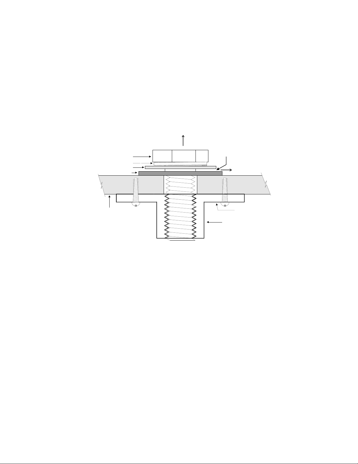
8.1.1 ACCEPTABLE MOUNTING POINT LOADING
A
A
The mounting points should be always be used so that either shear force is applied perpendicular to the
direction of and in tight proximity to the mounting hole or tension force is applied perpendicular to the
enclosure surface.
DANGER: Use the mounting points only as described above and shown in FIGURE 2. Do not use them in
such as way as to apply sideways leverage to them. Failure to follow this instruction could result in
immediate failure of the mounting points resulting in damage to the loudspeaker and serious injury or
death to personnel.
DIRECTION OF FORCE (TENSION)
CCEPTABLE
MOUNTING BOLT
LOCKWASHER
FLAT WASHER
RUBBER WASHER
NOTE: R1YOKE OR OTHER MOUNTING
FIXTURE GOES HERE BETWEEN THE
FLAT WASHER AND RUBBER WASHER
CCEPTABLE
DIRECTION OF FORCE (SHEAR)
FIBERGLASS ENCLOSURE
INSERT RETAINER FLANGE
(Fastened to enclosure)
MOUNTING POINT
1/2-13 THREADED INSERT
FIGURE 2: Mounting Point Detail
8.1.2 MOUNTING OPTIONS OTHER THAN THE R1 YOKE
Eyebolts: A forged, load-rated, shoulder eyebolt may be used to suspend an R1. The eyebolt must be screwed
in so that the shoulder firmly contacts the surface of the enclosure. In all cases the direction of pull on the
eyebolt and mounting point should be in tension not to exceed a maximum of 30º from the vertical axis of the
mounting point hole (See FIGURE 2). While a single mounting point so used can support the weight of the
loudspeaker with a greater than 5:1 design factor, a safety cable that can independently support the
loudspeaker must also be used. Other mounting points can be used as pull-back points to fix the aiming angle.
Custom Mounting Brackets: Custom brackets may be used. When mounting the loudspeaker the bracket
should pull directly either in tension or shear on the mounting point (See FIGURE 3). It is recommended that
any custom bracket be designed to utilize two mounting points on the opposite sides or top and bottom of the
enclosure.
8.2 ORIENTING AN R1
An R1 has a definite top/bottom and sides. However, a 180 degree inversion will not affect the coverage. When
the top of the enclosure is up, the input cable gland-nut will be down and to your right when looking directly
at the front of the loudspeaker. Also, the manufacturer's label is on the top of the enclosure. Once the top is
determined, you can properly orient the loudspeaker for your particular application according to the specified
coverage pattern.
© 2015 Community Professional Loudspeakers page 15
Page 16
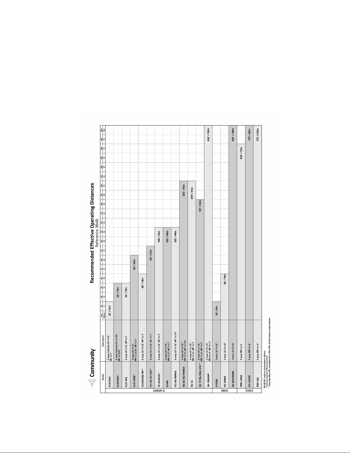
8.2.1 THROW DISTANCE AND SOUND LEVELS
The chart below helps answer the question, “how far can it throw?” The chart shows the maximum distance at
which a given model can reach 96 dB SPL on the A Scale (speech range). Consider a high-school football
stadium where the crowd noise is 86 dBA. At the recommended distance, an R.25 or R.5 would provide 10 dB
headroom above the crowd noise. Even if the crowd noise reaches 90 dBA, the R.25 or R.5 would still provide 6
dB of headroom which is acceptable for voice paging and announcement systems (use a limiter to avoid
clipping). In larger facilities, crowd noise can exceed 100 dBA. At motor racing events, racing noise can exceed
120 dBA near the track. It is impractical and unsafe to try to page above these levels. It’s better to train
announcers to wait until the crowd (or motor noise) quiets down and to repeat the page.
FIGURE 3: Recommended Operating Distances
© 2015 Community Professional Loudspeakers page 16
Page 17
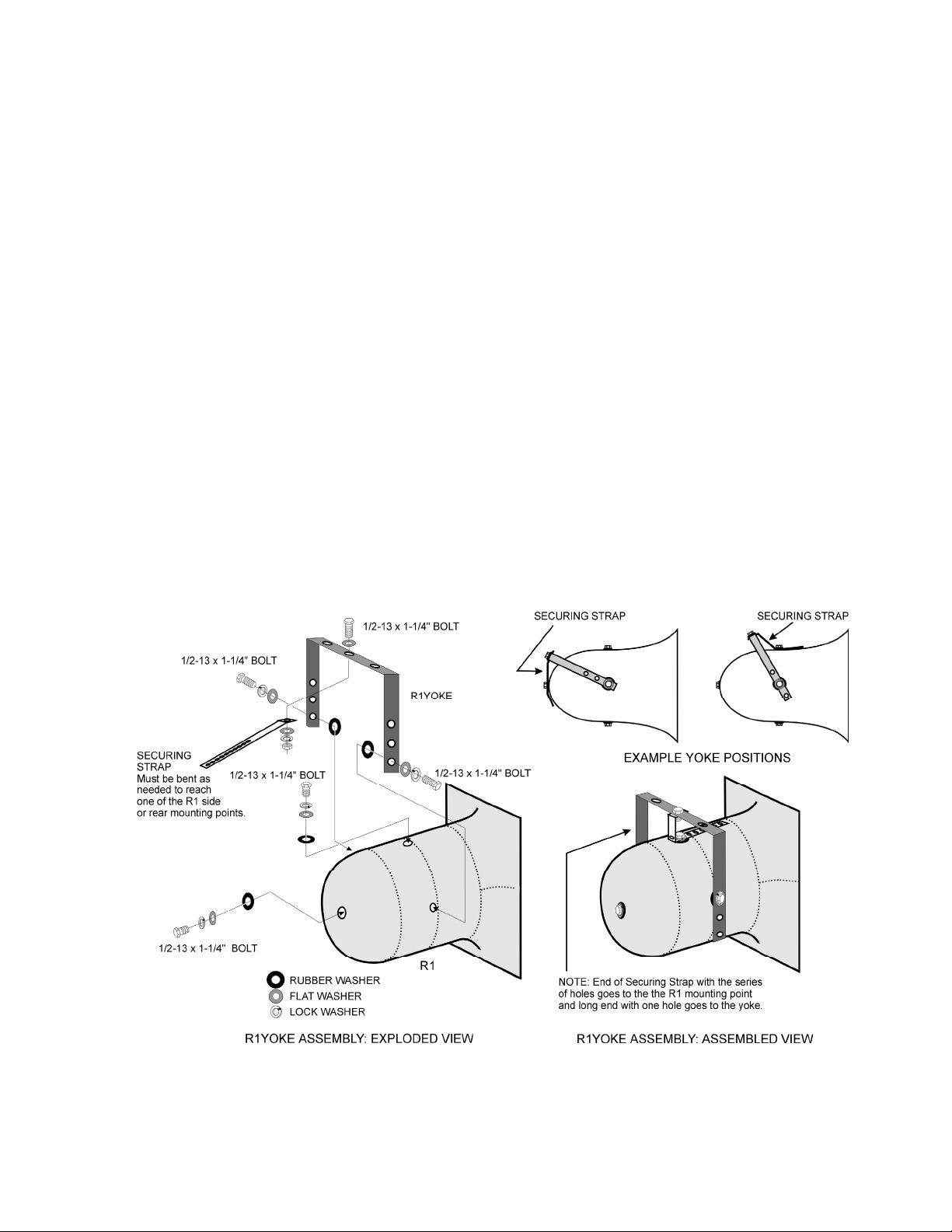
8.3 INSTALLING THE R1 MOUNTING YOKE
CAUTION: The R1 Mounting Yoke is specifically designed to provide a high degree of safety in R1
installations. It is highly recommended for mounting an R1. Other mounting methods should be
carefully considered so that undue strain and possible failure of the mounting points does not occur
(See SECTION 8.1.1)
CAUTION: In order to maintain the weather-resistant integrity of an R1, all five rubber washers
supplied with the R1 mounting point hardware must be used and be flush against the enclosure when
the R1 is mounted.
The yoke has three 17/32 in. (13.5 mm) holes in the crossbar. There is a fourth hole on one of the legs near the
crossbar. These holes are intended for attachment of the yoke to the structure to which the R1 is to be
mounted. The hardware used for the attachment must be load-rated for the intended purpose. Also insure
that the structure you are attaching to is capable of supporting the loudspeaker and yoke assembly. This must
include any torque load that may be applied to the structure as a result of the loudspeaker/yoke position and
aiming angle. For outdoor installations wind loading must also be taken into account. It is recommended that a
qualified and licensed structural engineer approve the mounting design.
8.3.1 R1 YOKE PARTS LIST
(All other hardware must be supplied by the installer.)
(1) Yoke Bracket (see FIGURE 6)
(1) Aluminum Securing Strap
(1) 1/2-13 x 1-1/4 in. (32 mm) stainless steel bolts
(1) 1/2-13 stainless steel hex nut
(1) 1/2 in. stainless steel flat washer
(1) 1/2 in. stainless steel lock washers
FIGURE 4: R1 YOKE Assembly
© 2015 Community Professional Loudspeakers page 17
Page 18

8.3.2 R1 YOKE MOUNTING PROCEDURE (See FIGURE 4)
Normally the yoke should first be attached to the R1 then the entire assembly mounted to a structure.
However in some cases it may be desirable to mount the yoke and secure it in place before mounting the R1 to
the yoke. Depending on the situation the sequence of the following mounting procedure may have to be
modified to facilitate the work. Nonetheless, the instructions and precautions about use of the hardware
should still be followed. The R1 Yoke is attached to the R1 and the Securing Strap is used to lock in the angle of
the R1 within the yoke.
1. To attach the yoke to the R1, first determine whether the yoke will be attached to the sides or top/
bottom of the loudspeaker. This will depend on what the yoke is to be mounted to and the how the R1
must be oriented when positioned for proper coverage (See SECTION 8.2). There are 3 holes on each side
of the yoke. The particular holes to use will depend on the clearance due to the aiming angle of the R1
needed within the yoke.
2. Once the position of the yoke is determined, remove two supplied 1/2-13 stainless steel mounting
bolts, with the lock, flat, and rubber washers from the mounting points where the yoke is to be attached.
3. Position the loudspeaker within the yoke making sure that the large rubber washers sit between the
yoke and the enclosure. Screw the 1/2-13 x 1-1/4 in. (32 mm) bolts, supplied with the R1, into the
mounting holes using the rubber washers, flat washers, and lock washers removed in step 2. Tighten
only enough so as to allow the yoke to move as needed for the rest of the procedure. The rubber washer
has a 7/16 in. (11 mm) hole so it fits quite snugly around the mounting bolts to form the weather seal for
the R1 mounting hole. It also provides some friction to help hold the yoke in position until completely
secured.
4. Mount the R1 and its attached yoke to the structure that will support it. If the center hole on the yoke
crossbar is used as one of the yoke mounting points you need to attach the attach the Securing Strap to
this hole at the same time you mount the yoke to the structure that will hold the R1 assembly. In
addition to attaching the Securing Strap to the yoke, the supplied stainless steel 1/2-13 x 1-1/4 in. bolt
(32 mm), 1/2 in. flat washer, 1/2 in. lock washer, and 1/2-13 hex nut can be used as the mounting bolt for
the yoke. In any case, the Securing Strap attaches to the yoke using the end with a single 9/16 in. (14
mm) hole in it. The Securing Strap is positioned on the underside of the yoke crossbar.
5. After properly securing the yoke to the structure, adjust the final aiming angle of the R1. Once the
aiming angle is set, carefully bend the Securing Strap towards the nearest mounting point on the R1 so
that one of the series of holes in the Strap lines up with the selected mounting point. This may involve
forming the strap into a "U" shape (as shown in FIGURE 3 "Assembled View") to reach one of the
remaining side mounting points or the rear mounting point.
6. Attach the Securing Strap to the mounting point on the R1 enclosure determined in step 5 using the
1/2-13 x 1-1/4 in. bolt, rubber washer, flat washer and lock washer supplied with the R1 mounting point.
Make sure that the rubber washer is located between the Securing Strap and the enclosure.
7. Firmly tighten the bolts holding the yoke to the R1 enough to seat the lock washer. Be careful not to
over-tighten as, given the size wrench that typically will be used, it is possible to apply excessive torque.
8. Lastly ensure that the attachment bolt used to attach the Securing Strap to the R1 is securely
tightened.
CAUTION: Any of the mounting bolts supplied with the R1 that are not used for mounting must be left in
place with their rubber washers and firmly tightened to maintain the integrity of the weatherproofing.
© 2015 Community Professional Loudspeakers page 18
Page 19

8.4 WEATHER RESISTANCE (Grille information does not apply to BNG models)
All R1s are highly weather-resistant by design. The all-fiberglass enclosure is virtually impervious to the
effects of weather. The grille is designed to prevent rain intrusion into the mouth of the loudspeaker. The R1
grille and supplied yoke are treated with Community’s proprietary dual-layer powder coat process which
includes a zinc-rich epoxy inner layer of extremely durable, corrosion fighting and abrasion resistant
elements, plus a UV-resistant outer layer of polyester powder coat to inhibit fading, peeling and cracking. All
external mounting hardware is stainless steel. The speaker cable gland-nut is made of polypropylene and
approved for outdoor electrical installation. The high frequency HF driver has a titanium diaphragm which is
an inherently weather-resistant material. The low frequency cone has been treated with a hydrophobic
water-resistant coating.
8.4.1 MAINTAINING WEATHER RESISTANCE
There are several things that must be observed when installing an R1 in order to maintain its weatherresistant integrity for outdoor use.
1. We recommend angling the R SERIES loudspeaker at least 5 degrees downward so as to reduce
the possibility of rain and other precipitation compromising the performance of the loudspeaker.
2. All five mounting holes must be sealed off with the stainless steel bolts, washers, and rubber washers
supplied. If, for any reason, these bolts must be removed, seal off the hole with silicone caulking or
some other suitable weather-tight sealant.
3. The rubber washers supplied with the mounting bolts must always seat against the enclosure.
4. The gland-nut securing the loudspeaker cable to the enclosure is sealed at the factory. Do not attempt
to remove this nut or the weather-tight seal will be broken. If it is desired to replace the gland-nut
with a jack, the jack must be a weather-proof design. It must be suitably sealed to the enclosure with
silicone caulk or some other suitable weather-tight sealant. The Neutrik model NL4MP is an excellent
connector for this purpose. The gland-nut should be at the bottom when mounting. Leave a “drip
loop” so water will not migrate toward the loudspeaker.
5. The grille assembly is designed to prevent normal and wind-driven rain from directly entering the
mouth of the loudspeaker. The grille is not designed to withstand such things as being directly
sprayed from a hose; therefore, this should be avoided.
6. If you use any hardware in place of the stainless steel screws, bolts, nuts, and washers supplied, it
should also be made of stainless steel.
CAUTION: If the above instructions are not observed, the weather-resistant integrity of an R1 can be
compromised. This can result in damage to or failure of the hardware or internal components which
will void the warranty.
8.4.2 MECHANICAL INSTALLATION AND SAFETY
DANGER: The loudspeakers described in this manual are designed and intended to be ‘flown’ or
suspended for maximum acoustical performance using a variety of rigging hardware, means, and
methods. It is essential that all installation work involving the suspension of these loudspeaker
products be performed by competent, knowledgeable persons who understand safe rigging practices.
Severe injury and/or loss of life may occur if these products are improperly installed.
Important Notes on Rigging Loudspeakers
There are three areas of responsibility for rigging loudspeakers. The first is the building structure. Always
consult with the building architect or structural engineer to assure the ability of the structure to support the
loudspeaker system. The second area of responsibility is the loudspeaker itself. Community certifies its
loudspeaker systems for suspension when they are properly installed according to our published guidelines.
The third area of responsibility is everything between the loudspeaker and the building structure and the
actual process of installation. The installing contractor assumes this responsibility. Loudspeaker rigging
should be performed only by certified rigging professionals using certified rigging hardware chosen for the
specific application. Prior to installation, the contractor should present a rigging plan, with drawing and
detailed parts list, to a licensed structural engineer (P.E.) or architect for written approval.
© 2015 Community Professional Loudspeakers page 19
Page 20

9 OPERATING PRECAUTIONS
9.1 LIMITING
Although R1s have built-in PowerSense™ DDP circuitry to help prevent damage to the drivers from excessive
power, electronic limiting is strongly recommended. This is especially true if an R1 is installed in relatively
inaccessible locations or is being operated by personnel who are not trained operators. In such cases the
limiter should be used as a hard-line device to prevent amplifier clipping and preventing output voltages in
excess of 40V RMS and 95V peak power. The following are recommended settings for this purpose. Set the
limiter threshold to actively limit the audio signal if the average rises above 40V. In no case should the limiting
allow amplifier clipping. If adjustments are available: set the attack time to a moderate time (10 msec is a good
starting point) and the release time to fast (1 msec is a good starting point). This will allow most peak
(dynamic) information to pass. The limiting ratio should be set to at least 10:1. Although this may compromise
audio quality when limiting, you are protecting the drivers at this point and therefore audio quality should be a
secondary consideration.
9.2 AMPLIFIERS WITH BUILT-IN LIMITING
Recently power amplifier manufacturers have introduced amplifiers with either built-in limiting or accessory
limiting modules. In both cases these limiters are usually designed to prevent the amplifier from clipping. This
type of limiting is acceptable to use in lieu of a stand-alone limiter because it is easy to set-up, is specifically
designed for the amplifier, and in most cases, is tamper-proof. This assumes that the amplifier output is sized
as recommended in CHAPTER 6.
10 SERVICING
10.1 Tools Required for Servicing
#2 Phillips head screwdriver
11/32 in. Wrench or nut driver (crossover)
7/16 in. Wrenches or nut drivers (HF horn brackets)
10.2 High Frequency Driver
The high frequency driver has a field replaceable driver/voice coil assembly. The high frequency horn/driver
assembly is retained by brackets secured to the inside of the bass horn and eyebolts secured to the LF driver.
To remove the driver, first remove the grille. Then disconnect the Molex plug from the side of the cylindrical
phase plug housing behind the HF horn itself. Remove the 4 Phillips head screws that attach the eyebolts to
the LF driver frame. Then detach the entire HF driver/horn/LF phase plug assembly from the enclosure by
removing the four 1/4-20 hex head bolts and nuts that secure the HF brackets to the R1 bass horn. Note the
orientation of the horn assembly to the enclosure so as to re-install it correctly. Remove the 4 Phillips head
screws from around the rear horn flange and lift out the HF driver. Detach the wiring to the driver noting the
polarity of the connections for later correct attachment (See FIGURE 4). The driver may then be unbolted from
the HF horn.
To reinstall, reverse this procedure, ensuring proper orientation of the horn. Be careful to avoid damaging the
LF driver cone with the eyebolts or back of the phase plug when putting the assembly back into the low
frequency horn. Also avoid damaging the inside of the horn with the horn brackets.
10.3 Low Frequency Driver
This driver is accessed by first removing the high frequency horn/driver assembly as detailed in SECTION 10.3.
The low frequency driver can then be removed by unscrewing the 4 remaining Phillips head bolts from the
enclosure. Detach the wiring to the driver noting the polarity of the connections for later correct attachment
(See FIGURE 4). To reinstall, reverse this procedure.
© 2015 Community Professional Loudspeakers page 20
Page 21
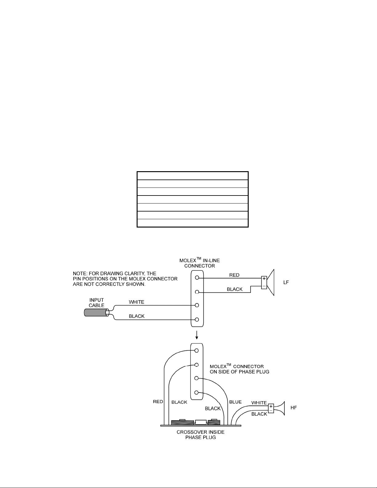
10.4 Crossover
The crossover is located inside the low frequency phase plug attached to the rear of the high frequency
horn/driver assembly. It is accessed by first removing the high frequency horn/driver/phase plug assembly
as detailed in SECTION 10.3 then removing the phase plug from the back of the HF horn/driver. Remove the
crossover by unscrewing the 8-32 nut and bolt that hold it to the rear of the phase plug. For complete removal
you must detach the Molex plug from the phase plug which is held on by hot melt glue that can be cut away.
Alternately you can either cut the wires from the plug to the crossover or unsolder the wires from the
crossover board. To reinstall, reverse this procedure ensuring that the crossover is oriented so that it does not
contact the eyebolts in the bottom of the phase plug. Reattach the Molex plug into the side of the phase plug
using hot melt glue or reattach the wires if they were cut or unsoldered. If cut, be sure to insulate any bare
wire where you reconnect them.
10.5 Replacement Parts List
The following replacement parts may be ordered through authorized Community Service Stations Please
contact Community for your nearest Service Station.
REPLACEMENT PARTS
12 in. LF Driver
HF Driver
HF Driver Replacement Diaphragm
Internal Crossover
Wire Harness
Grille Assembly
Table 2: Replacement Parts
(Note: The specific replacement part number will depend on the specific R1 model)
FIGURE 5: R1 Wiring
© 2015 Community Professional Loudspeakers page 21
Page 22
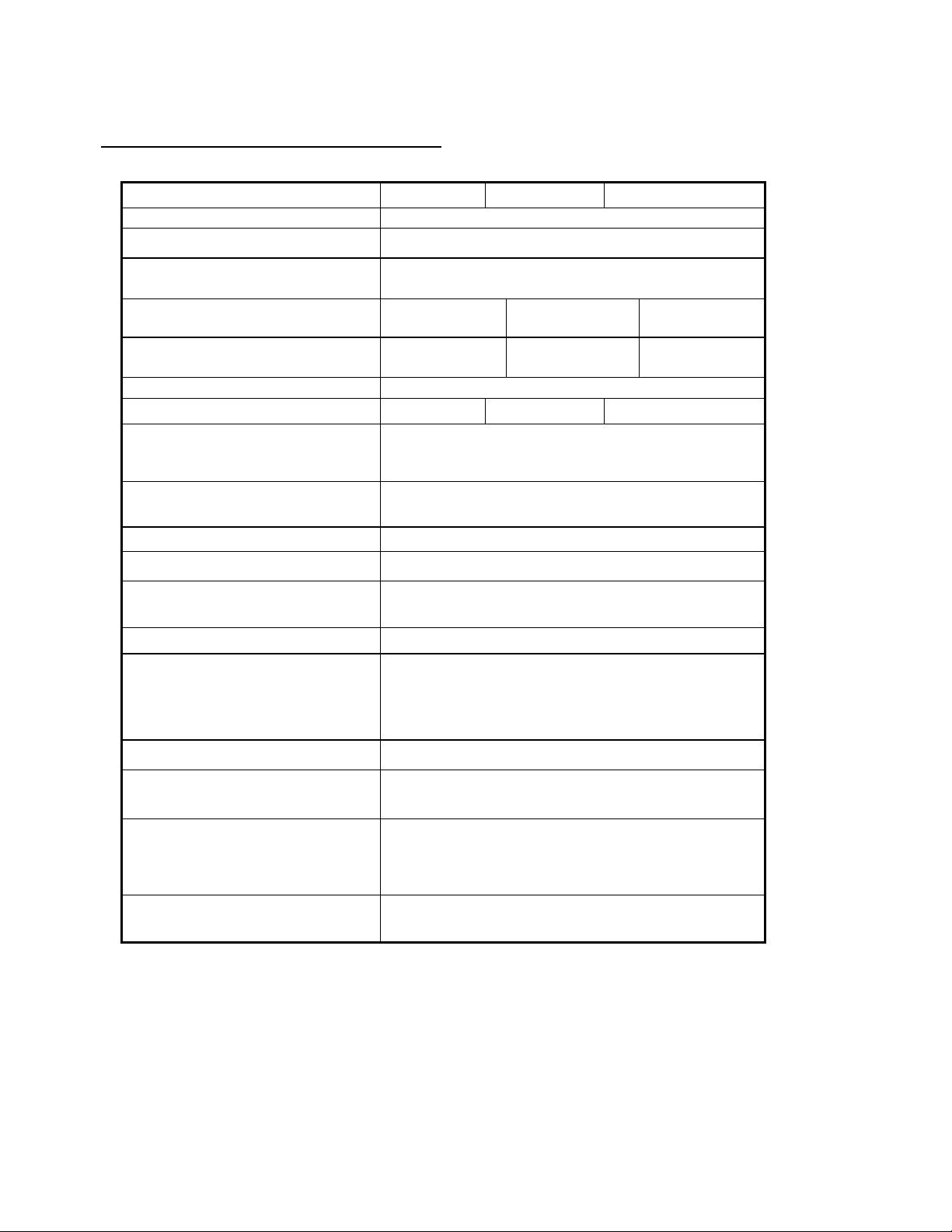
11 TECHNICAL SPECIFICATIONS
Specifications
Model: R1-66 R1-64 R1-94
Loudspeaker Type: 2-way coaxial, horn-loaded
Frequency Response: 90 Hz to 16 kHz
Power Handling (RMS / Program): 200W / 500W
(40V RMS, 89V momentary peak)
Sensitivity:
(1W/1m 100-16k Hz) 105 dB
Nominal Impedance:
8 Ohms
(min 5.7 Ohms)
Crossover Point: 1,200 Hz
Dispersion: (Nominal H x V) 60º x 60º 50º x 35º 80º x 35º
Loudspeaker Components:
LF
Speaker Protection:
1 x 12 in. / 305 mm)
HF
1 x 1 in. / 25 mm titanium
PowerSense™ DDP
Ferrofluid-cooled LF driver
Input Connection: 4 ft / 1.2 m x 16-2 SJOW Neoprene Cable
Enclosure Material: All fiberglass
105 dB
8 Ohms
(min 5.5 Ohms)
1
104 dB
8 Ohms
(min 5.7 Ohms)
Color: Standard
BNG models
50 % gray
2
Black
Mounting Points: 5 x 1/2 in.-13 threaded inserts
Grille: Standard
BNG models
Accessory Included:
Optional Accessory:
Dimensions: Height
Width
Depth
Rear Diameter
Weight: Standard
BNG models
Note: Specifications are subject to change without notice.
1 DDP = Dynamic Driver Protection
2 See SECTION 5.1
3-layer WeatherStop™, light grey
(Zinc-rich epoxy dual-layer powder coated
perforated steel grille, foam, woven poly mesh)
2
None
Light grey, powder coated steel yoke bracket
TRC400 line transformer
(200W @ 8 Ohms, 400W @ 4 Ohms)
24.75 in. / 629 mm
24.75 in. / 629 mm
29.75 in. / 756 mm
16 in. / 406 mm
55.5 lb. / 25.2 kg
2
43.5 lb. / 19.7 kg
© 2015 Community Professional Loudspeakers page 22
Page 23
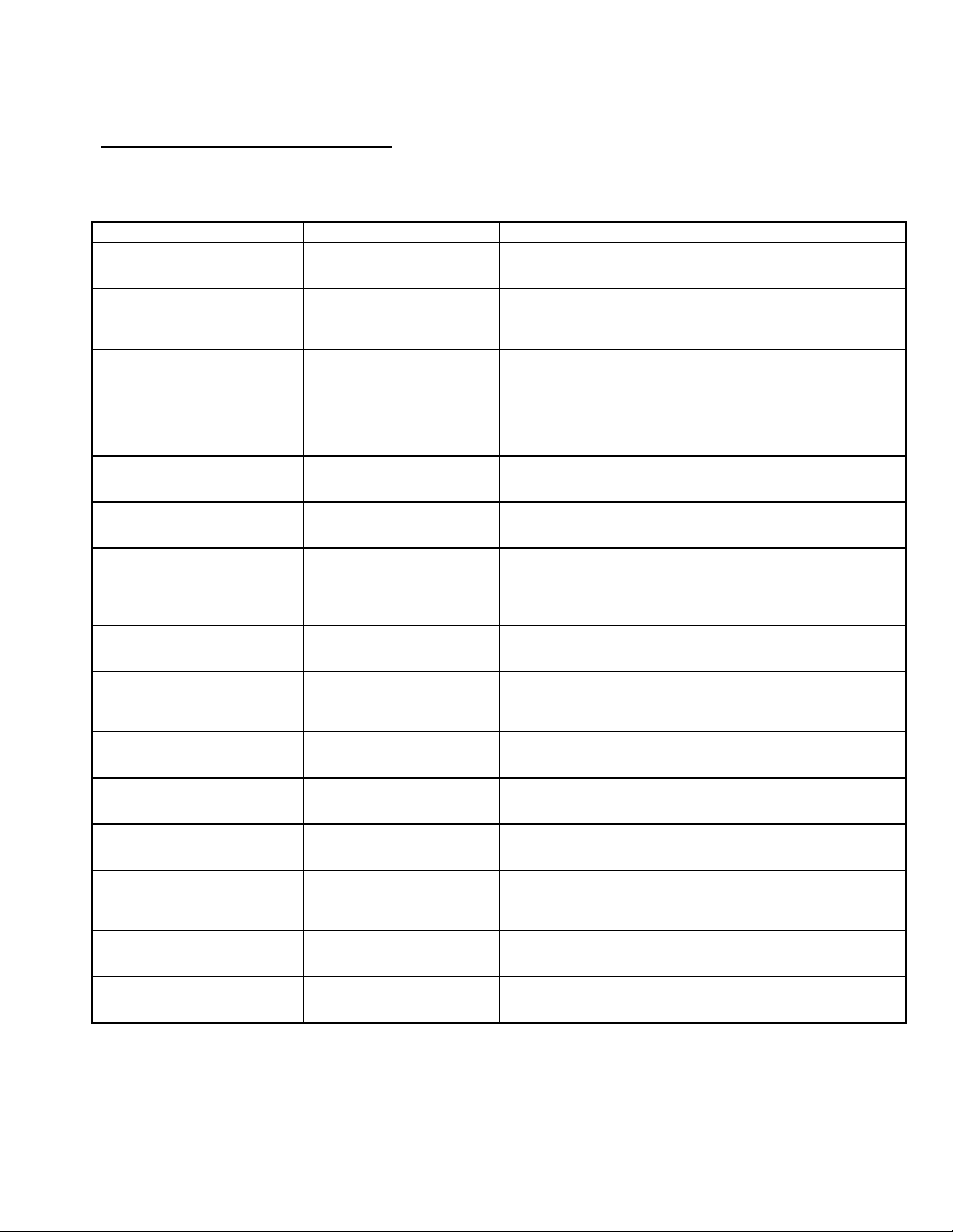
12 IN CASE OF DIFFICULTY
Should you have a problem with your Community R1 loudspeaker, find the symptom and follow the associated
“What To Do” instructions. Be aware that a particular symptom may have several possible causes. Please
refer to the appropriate section in this manual if you need more detailed information.
SYMPTOM PROBABLE CAUSE WHAT TO DO
No sound. Equipment is turned off.
No sound Bad or open connection
No sound
No sound or very low volume. System control is turned down.
Low volume level.
Low volume level.
Volume level drops and comes
back.
Sound cuts in and out. Bad connection. Check all connections an cabling for shorts or loose connections.
During high output operation the
volume drops suddenly and does
not come back.
Distortion, low volume, or no
volume from any or all drivers
Distortion from the loudspeaker at
higher volume levels.
Distortion from the loudspeaker at
higher volume levels.
No volume for the bass
frequencies.
Low or no volume for the high
frequencies.
Noises from the loudspeaker
(buzzes or rattles).
Noises from the loudspeaker
(buzzes or rattles).
Crossover or all the drivers
have completely failed
System electronic gain is too
low.
Signal or speaker wire
connection is shorted
The crossover protection
circuits have been activated.
The crossover protection
circuits have “given up”.
Cold/open solder joint on the
crossover or faulty wiring
connection.
Too little amplifier power.
Driver is malfunctioning.
Low frequency driver or
crossover is malfunctioning.
High frequency driver or
crossover is malfunctioning.
Grille or hardware is loose.
Driver is malfunctioning.
Check and make sure that all equipment in the audio signal path is
turned on. When turning on any piece of equipment, the amplifier
should be not be turned on until all equipment before it is turned on.
Make sure the signal and input wire connections for all connectors in
the system and to all terminal screws are properly connected or
soldered. Make sure all wire and cables are intact and not severed or
damaged.
This would be an unusual cause but could occur with severe abuse or
an adverse amplifier failure. All other possibilities should be explored
before assuming this is the cause. If it is, replace or repair the failed
components.
Check to make sure that the audio signal to the amplifier is high
enough to drive it properly. Check all volume/level controls and gain
switches in the system including the amplifier input attenuator.
Check to make sure that the audio signal to the amplifier is high
enough to drive it properly. Check all volume/level controls and gain
switches in the system including the amplifier input attenuator.
Make sure the wire connections inside all system connectors are not
shorted. Even one small wire strand shorting the +/- terminals either
before or after the amplifier can cause this problem.
This usually means that the loudspeaker is being constantly
overdriven and the crossover protection circuits are reducing the
power to the loudspeaker as a protective measure, which is normal.
Reduce the volume level to the loudspeaker.
This usually means that the loudspeaker was continually overdriven
for an extended period and the protection relays have “fused” in their
protect mode. The crossover must be repaired.
Using an ohmmeter, check the continuity of the crimp connectors, all
solder joints on the crossover and the wiring to the drivers. Also
visually inspect solder joints as cold joints may only malfunction with
higher current than an ohmmeter supplies. Repair as needed
If the amplifier being used is too low power, it will clip at higher
volume levels. Reduce the volume level or use a more powerful
amplifier equal to the loudspeaker’s “Program” power rating.
Using a sine wave oscillator or wide range program at moderate
levels, listen to each driver to isolate the problem. Repair or replace
as needed.
Using an ohmmeter, measure the resistance of the input cable (with
the amplifier disconnected). If the meter does not read ~7 ohms, the
LF driver may not be working. Repair or replace as needed.
While right in front of the loudspeaker, listen at low level for high
frequencies. If some are heard and are not distorted, it is probably a
crossover problem. If distorted or no sound is heard, the HF driver
may not be working properly. Repair or replace as needed.
Make sure the front grille screws are firmly tightened; that any
external mounting hardware is tightened or secured from vibrating
(especially if chains or wires are used in the mounting).
Using a sine wave oscillator or wide range program at moderate
levels, listen to each driver to isolate the problem. Repair or replace
as needed.
© 2015 Community Professional Loudspeakers page 23
Page 24

13 WARRANTY INFORMATION
Field Service
Any driver or crossover service required is done from the front of the enclosure by removing the screws
around the edge of the grille. For warranty repair, contact Community directly or ask us for the location of
your nearest Authorized Service Center.
Transferable Warranty "(Limited)” Valid in the USA Only
Community loudspeaker systems are warranted in the USA to be free from defects in materials and
workmanship for a period of five years, as determined by one of the following two methods, whichever is
longer:
Starting from the date of retail purchase, as noted on the sales receipt from an authorized Community dealer,
OR
Starting from the date of manufacture, determined by the serial number, if the sales receipt is not available.
This warranty applies to the product; therefore, the remainder of the warranty period will be automatically
transferred to any subsequent owner.
This warranty applies only to failure of a Community loudspeaker caused by defects in materials and
workmanship during the stated warranty period. It does not apply to a unit that has been subjected to abuse,
accident, modification, improper handling/installation, or repairs made without factory authorization or by
anyone other than authorized
Community Field Service Stations. This warranty is void if the serial number has been defaced, altered or
removed.
Products covered by this warranty will be repaired or replaced at the option of Community, without charge for
materials or labor, provided all the terms of this warranty have been met.
© 2015 Community Professional Loudspeakers page 24
Page 25

Obtaining Warranty Service
Warranty service may be obtained from the factory, or from an authorized Field Service Station. For complete
warranty information please visit our website at www.communitypro.com/warranty.
To obtain factory or field warranty service for products purchased in the United States, return the product for
inspection to the address below, freight prepaid, in the original packaging. If the original packaging is not
available, call or write Community Warranty Service to obtain proper packaging materials or hand carry the
product to the nearest Field Service Station.
Factory Service Center:
Community Warranty Service
333 East Fifth Street
Chester, PA 19013-4511 USA
Call (610) 876-3400 for parts, service information or the nearest Authorized Field Service Station.
For factory service, please call (610) 876-3400 for a Return Authorization (R/A) number before shipping. The
following information must be included in the package:
Owner’s complete name, daytime phone number, return street address and return authorization
number.
The serial number of the product being returned and a copy of the retail sales receipt, if possible.
A complete description of the problem(s) experienced, including a brief description of how the
equipment is being used and with what brand, model and output power of amplifier.
Upon receipt, the service center will determine if the problem is covered under warranty. If covered under this
warranty, the product will be repaired or replaced, at Community’s option, and returned to the owner freight
prepaid. If the problem is not covered under this warranty, the owner will be notified of the problem with an
estimate of the repair costs.
Consequential and Incidental Damages: Community shall not be liable for any consequential or incidental
damages including, without limitation, injury to persons, property, or loss of use. Some states do not allow the
exclusion or limitations of consequential or incidental damages, so the above limitations and exclusions may
not apply.
This Community warranty is not extended by the length of time which an owner is deprived of the use of the
product. Repairs and replacement parts provided under the terms of this warranty shall carry only the
remaining portion of the warranty.
Community reserves the right to change the design of any product from time to time, without notice and with
no obligation to make corresponding changes in products previously manufactured.
While this warranty gives specific legal rights, there may also be other rights that vary from state to state. No
action to enforce this warranty shall be permitted ninety days after expiration of the warranty period.
Warranty Information and Service for Countries Other Than the USA
To obtain specific warranty information, visit the website at www.communitypro.com/warranty. To obtain
available service locations for countries other than the United States of America, contact the authorized
Community Distributor for your specific country or region.
This warranty applies only to failure of a Community loudspeaker caused by defects in materials and
workmanship during the stated warranty period. It does not apply to a unit that has been subjected to abuse,
accident, modification, improper handling/installation, or repairs made without factory authorization or by
anyone other than authorized Community Field Service Stations. This warranty is void if the serial number has
been defaced, altered or removed.
© 2015 Community Professional Loudspeakers page 25
Page 26
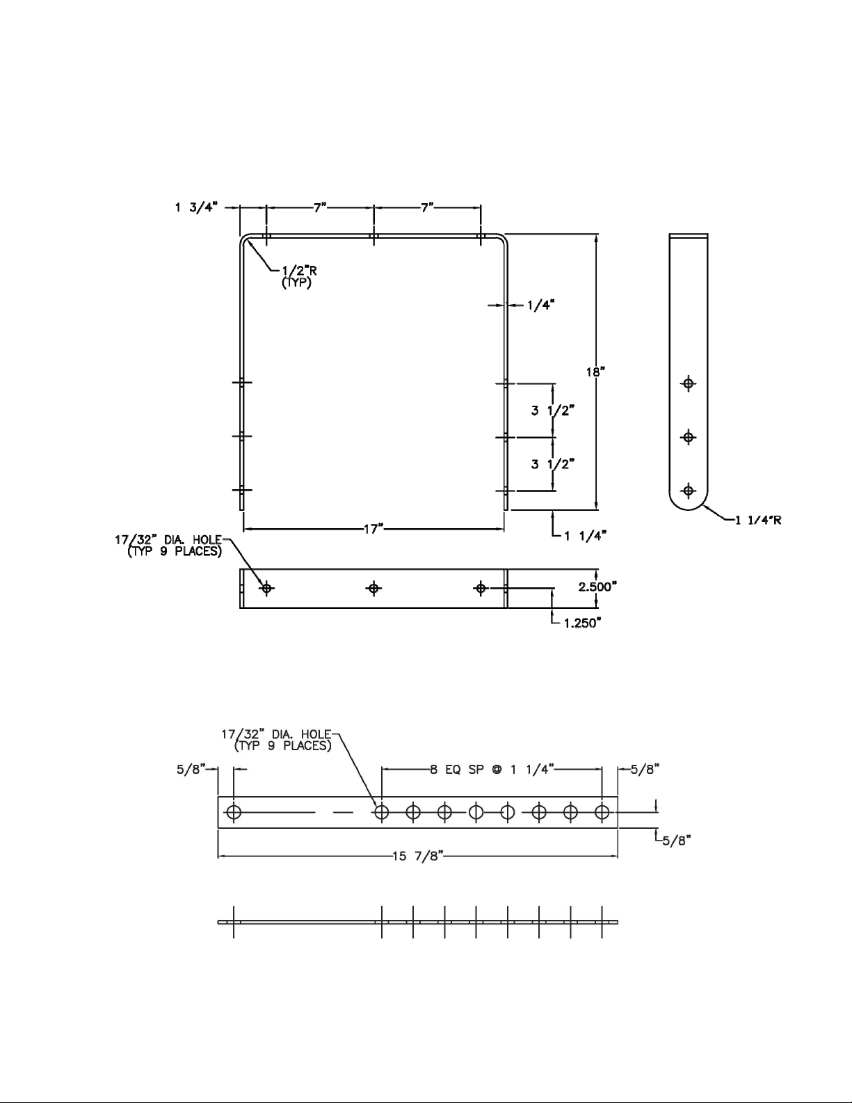
R1 Yoke
R1 Yoke Securing Strap
FIGURE 6: R1 YOKE AND SECURING STRAP
© 2015 Community Professional Loudspeakers page 26
Page 27

Notes
© 2015 Community Professional Loudspeakers page 27
Page 28

Community Professional Loudspeakers
333 East Fifth Street, Chester, PA 19013-4511
Phone: (610) 876-3400 Fax: (610) 874-0190
www.communitypro.com
© 2015 Community Professional Loudspeakers page 28
#105310 15SEP2015
 Loading...