

Community Point Source 600, Point Source 800, Subwoofer 800, Subwoofer 600 Installation And Operational Manual
Page 1

I SERIES
Installation and
Operation
Quick Start Guide
Models
Point Source 800 (IP8-xxxx)
Point Source 600 (IP6-xxxx)
Subwoofer 800
Subwoofer 600 (IS6-xxxx)
communitypro.com
(IS8-xxxx)
Page 2
IMPORTANT SAFETY INSTRUCTIONS
Always follow these basic safety precautions when using or installing I SERIES loudspeakers and
accessories:
• Read these instructions prior to assembly.
• Keep these instructions for reference.
• Heed all warnings.
• Follow all instructions, particularly those pertaining to rigging, mounting, hanging and electrical
connections.
• Do not use this apparatus near water.
• Clean only with dry cloth.
• Do not block any ventilation openings. Install in accordance with the manufacturer’s instruction.
• Do not install near any heat sources such as radiators, heat registers, stoves, or other
apparatus (including amplifiers) that produce heat.
• Only use attachments and accessories that are specified and approved by the manufacturer.
Refer all servicing to qualified service personnel. Servicing is required when the apparatus has been
damaged in any way, such as liquid has been spilled or objects have fallen into the apparatus, the
apparatus has been exposed to rain or moisture, does not operate normally, or has been dropped.
The terms CAUTION, WARNING, and DANGER may be used in this manual to alert the reader to
important safety considerations. If you have any questions or do not understand the meaning of
these terms, do not proceed with installation. Contact your local dealer, distributor, or call Community
directly for assistance. These terms are defined as:
CAUTION: describes an operating condition or user action that may expose the equipment
or user to potential damage or danger.
WARNING: describes an operating condition or user action that will likely cause damage
to the equipment or injury to the user or to others in the vicinity.
DANGER: describes an operating condition or user action that will immediately damage
the equipment and/or be extremely dangerous or life threatening to the user or to others
in the vicinity.
These installation instructions are for use by qualified personnel only. To reduce the risk of fire or
electric shock do not perform any servicing other than that contained in the operating instructions
unless you are qualified to do so.
UNPACKING / INSPECTION
Community I SERIES loudspeakers are engineered
and manufactured to be rugged and they are
carefully packed in sturdy cartons. However, it
is recommended to thoroughly inspect each unit
after it has been removed from the packaging, as
damage could occur during shipping.
Please note that once the shipment has left
your dealer or the Community factory, the
responsibility for damage is always borne by
the freight company. If damage has occurred
during shipping, you must file a claim directly
with the freight company. It’s very important to
contact the freight company as soon as possible
after receiving your shipment, as most freight
companies have a short time limit within which
they will investigate claims. Make sure to save
the carton and the packing material, as most
claims will be denied if these materials are not
retained. Your Community dealer and the factory
will try to help in any way they can, but it is the
responsibility of the party receiving the shipment
to file the damage claim.
It is always a good idea to retain the carton and
packing materials, if possible, in the event that
the unit may need to be returned to your dealer
or distributor for repair in the future.
IN THE CARTON
Each shipping carton contains the following:
• Loudspeaker (fully assembled)
• Rubber feet and attachment screws
(subwoofers only)
• Information packet
RIGGING AND ELECTRICAL SAFETY
IMPORTANT: The loudspeakers described in this manual are designed and intended to be
mounted to diering building surfaces using a variety of rigging hardware, means and
methods. Installation of loudspeakers should only be performed by trained and qualified
personnel. All electrical connections must conform to applicable city, county, state, and
national (NEC) electrical codes.
DANGER: All rigging fittings must be fully tightened and secured. Any missing fasteners or
parts will compromise the structural integrity of the enclosure and constitute a safety
hazard. Do not suspend this loudspeaker unless all fasteners are securely in place!
. DANGER: It is possible to experience severe electrical shock from a power amplifier.
Always make sure that all power amplifiers are in the “OFF” position and unplugged from
an AC Mains supply before performing electrical work.
IMPORTANT: Refer to the sections on installation and connections later in this manual for
additional information on rigging and electrical safety.
IMPORTANT: The flat-head hex-drive rigging screws that come installed in each enclosure
must either be replaced with rigging brackets and threaded fasteners, or they must be
kept in place to seal the enclosure from air leaks. If the rigging fittings do not remain
sealed, air leaks will occur in the enclosure that will compromise the low-frequency
performance with distortion, reduced output, and premature driver failure.
DANGER: I SERIES rigging fittings are
rated at a Working Load Limit (WLL) of
225 lbs (102.1 kg) with a 10:1 safety
margin. No single rigging fitting should ever be
subjected to a load that is greater than this
stated limit. Failure to heed this warning could
result in injury or death!
CAUTION: Installation of
I SERIES loudspeakers should
only be performed by trained
and qualified personnel. It is strongly
recommended that a licensed and
certified professional structural
engineer approve the mounting.
Severe injury and/or loss of life may
occur if this product is improperly
installed.
Page 2 Quick Start Guide
I SERIES IP800/IP600, IS800/IS600
Page 3
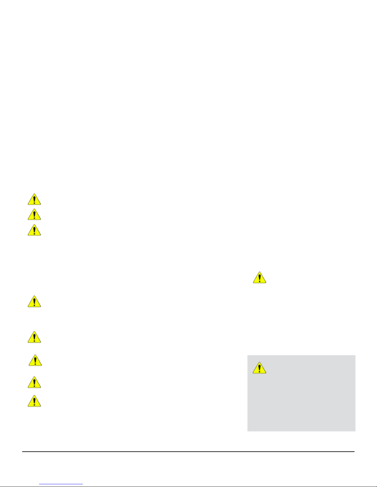
PRODUCT NAMING CONVENTION
I SERIES presents a logical way of easily
deciphering each model's characteristics
(family, type, level, number and size of woofer,
crossover bands, and horn pattern). The
diagram at right demonstrates the product
naming convention behind each model.
IP8-1122/96B translates as:
I SERIES Point Source 800
Single 12-inch Two-way, 90° x 60°, Black
I P 8 1 12 2 96 B
Product Family
I = I SERIE S
Product Typ e
P = Point S ource
C = Compact
S = Subwoo fer
M = Monit or
Q = High Q
Trim Level
8 = 800
6 = 600
–
LF Qty
LF Size
Use 2 digi ts:
08 = 8-inc h
12 = 12-inch
Crossover Bands
1-way
2-way
3-way
Omit for S-type
Form/Mode
/ = Indoor s tandard
T = Transfor mer
WR = Weath er-resistan t
WT = WR +Tran sfo rme r
C = CTO (Con figured)
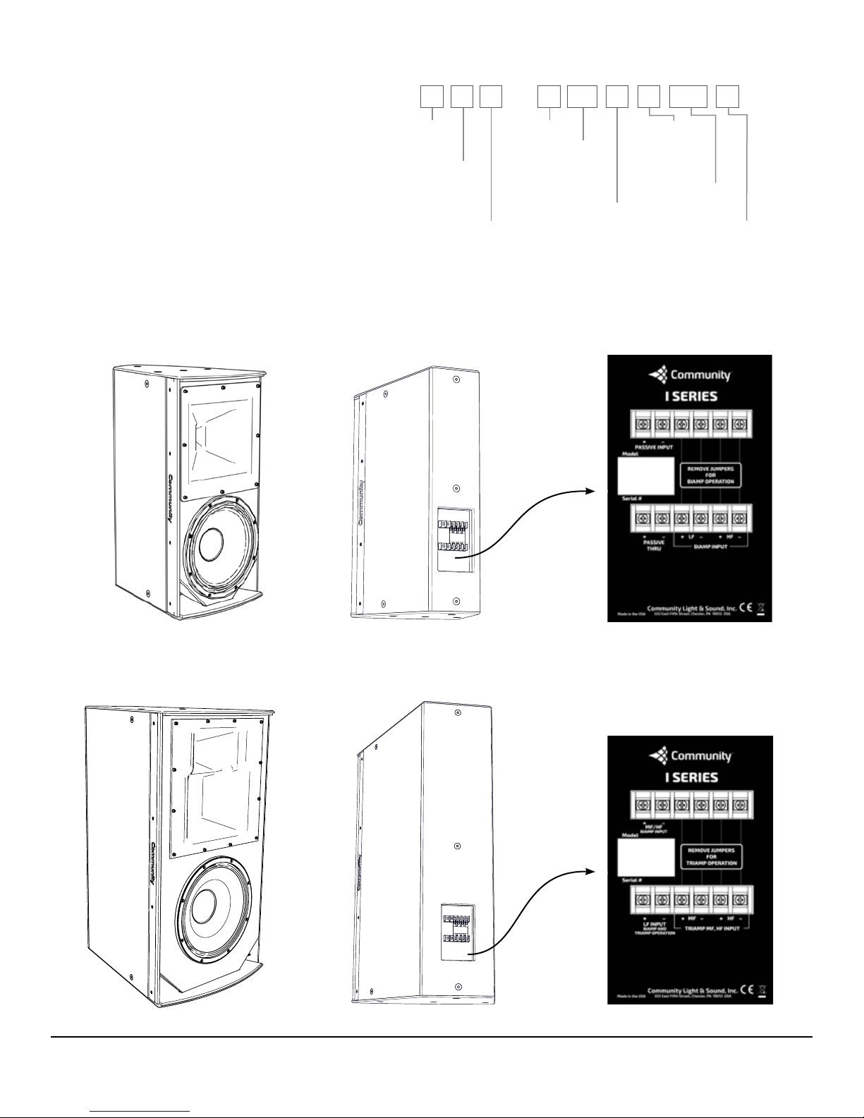
PRODUCT REPRESENTATION
I SERIES LOUDSPEAKER (2-WAY TYPICAL)
Models: IP8-1122/xx, IP8-1152/xx, IP6-1122/xx, IP6-1152/xx - each model has 6 horn patterns
/
Horn Pattern
H x V
(Omitted for S-type)
Cabinet Color
B = Black
W = White
(WR and W T are Grey
by defa ult - no color
code is sh own)
IP8-1122, IP6 -1122
I SERIES LOUDSPEAKER (3-WAY TYPICAL)
Models: IP8-1153/xx - 3 horn patterns
IP8-1153
2-way Input Panel
3-way Input Panel
I SERIES IP800/IP600, IS800/IS600 Quick Start Guide Page 3
Page 4
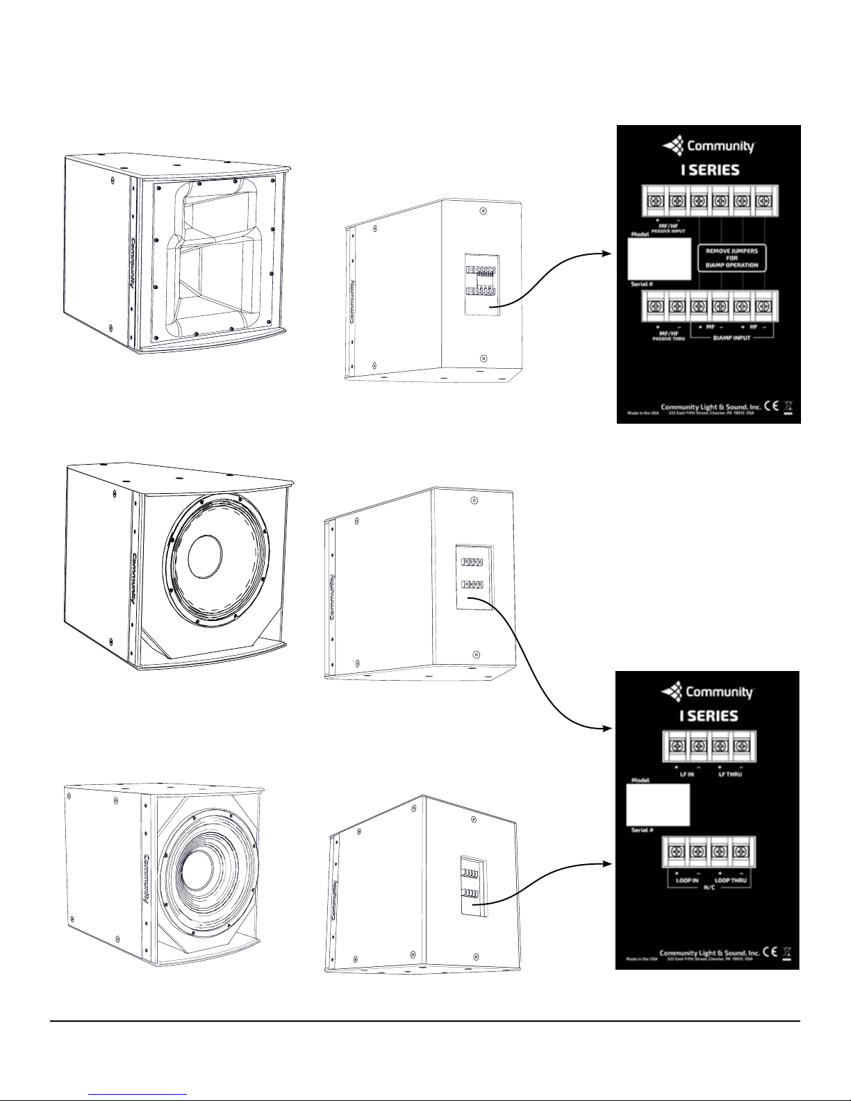
PRODUCT REPRESENTATION
MID-HIGH FREQUENCY LOUDSPEAKER
Models: IP8-0002/xx - 3 horn patterns
IP8-0002
LOW FREQUENCY LOUDSPEAKER
Model: IP8-1151
IP8-1151
SINGLE DRIVER SUBWOOFER (TYPICAL)
Models: IS8-112, IS8-115, IS8-118, IS6-112, IS6-115, IS6-118
MF/HF Input Panel
IS8-115
I SERIES IP800/IP600, IS800/IS600 Quick Start Guide Page 4
Single Sub Input Panel
Page 5
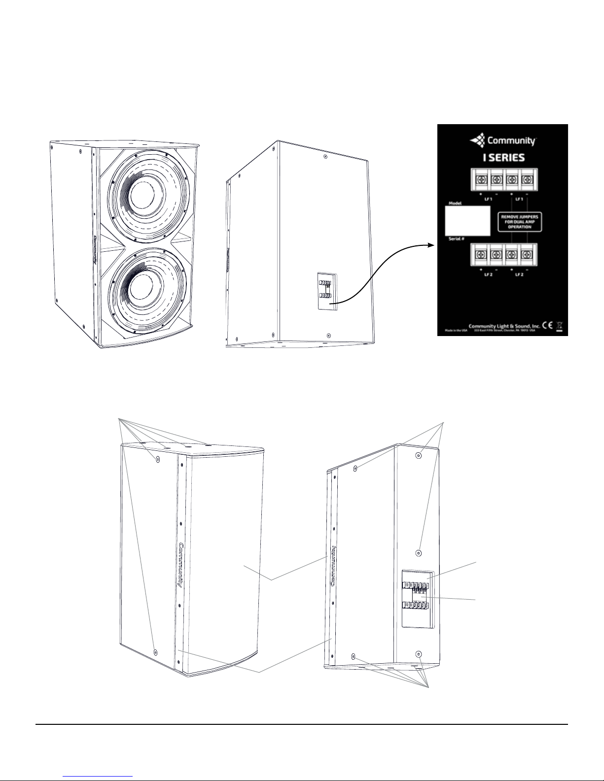
PRODUCT REPRESENTATION
DUAL DRIVER SUBWOOFER (TYPICAL)
Models: IS8-212, IS8-215, IS8-218, IS6-212, IS6-215, IS6-218
IS8-218
Dual Sub Input Panel
EQUIPMENT BASICS
Mounting Points
(M10 Flat Head Screws)
Grille
Aluminum Grille
Retainer
Mounting Points
(M10 Flat Head Screws)
Note: Weather-resistant (WR)
models are ordered
preconfigured for single or
multi-amp connections and have
a sealed cover over the input
panel. A 12 ft (3.6m) 14 ga cable
though a sealed gland nut is
provided for connection to the
amplifier.
Input panel
Jumper
Mounting Points
(M10 Flat Head Screws)
Page 5 Quick Start Guide
I SERIES IP800/IP600, IS800/IS600
Page 6

CONNECTIONS AND INSTALLATION
USE THE CORRECT WIRE OR CABLE
All I SERIES loudspeakers are fitted with captive-clamp terminal blocks on the
input panel to connect to the amplifier. Terminating the wires with a spade or
ring connector (Figure 1.) is recommended for secure connections. The maximum
width of the ring or spade lug should be 0.375" (9.5mm), or less. The terminal
screws are #8 (M4). The maximum wire size that can be accommodated for bare
wire connections is 10 AWG (5.26 mm
2
).
Ring
terminal
Note: Wire insulation colors may vary depending upon region or manufacturer. Be consistent with
conductor color use throughout the system.
Weather-resistant I SERIES models are ordered preconfigured for passive or
biamp/triamp operation and have a 12' (3.6m) 14 ga cable passing through a
sealed gland nut and input panel cover. Do not remove the gland nut or input
panel cover as this will defeat the weather-resistance of the connection. If you
must remove the input panel or gland nut, it must be reattached and resealed
with a silicone or other similar sealant to maintain the weather-resistance of the
loudspeaker.
CONNECTION: LOUDSPEAKER INPUT PANEL
The input panels on the two-way loudspeakers can be wired in passive or biamp
configurations. The three-way can be wired in biamp or triamp modes. The dual
subwoofers can be wired in single amp or dual amp modes. The input panels
on these models have a jumper that must be placed correctly in order for it to
function in the designated mode. See Figures 2a-2d for the jumper positions.
Spade
terminal
Figure 1. Wire Connectors
IMPORTA N T: All electrical
installation connections for
loudspeaker lines are
subject to all applicable
governmental building and fire
codes. The selection of appropriate
electrical hardware to interface with
the I SERIES loudspeaker lies solely
with the installation professional.
Community recommends that an
appropriately licensed engineer,
electrician, or other qualified
professional identify and select the
appropriate conduit, fittings, wire,
etc. for the installation.
PASSIVE
Figure 2a. Two-way input panel
Jumper down for Passive operation. Jumper up (or removed) for Biamp operation.
Page 6 Quick Start Guide
BIAMP
I SERIES IP800/IP600, IS800/IS600
Page 7

CONNECTION: LOUDSPEAKER INPUT PANEL (continued)
TRIAMP
BIAMP
TRIAMP
BIAMP
Model
Serial #
I SERIES
+–
LF IN
+–+–
LOOP IN LOOP THRU
+–
LF THRU
N/C
BIAMP
TRIAMP
Figure 2b. Three-way input panel
Jumper down for Biamp operation.
Jumper up (or removed) for Triamp operation.
SINGLE AMP
Community Light & Sound, Inc.
Made in the USA
I SERIES IP800/IP600, IS800/IS600 Quick Start Guide Page 7
333 East Fifth Street, Chester, PA 19013 USA
Figure 2c. Single driver
subwoofer input panel
No Jumper
SINGLE AMP DUAL AMP
Figure 2d. Dual driver subwoofer input panel
Jumper down for Single Amp operation.
Jumper up (or removed) for Dual Amp operation.
Page 8

GRILLE REMOVAL / HORN ROTATION
The horns on full-range loudspeakers
(IP6/8-1122, IP6/8-1152, IP8-1153
and IP8-0002) can be rotated 90° by
removing the grille, rotating the horn
and then reinstalling the horn and
grille.
Remove the screws holding one
Community grille retention bar to the
cabinet. Remove the bar and loosen
the grille. Then remove the other
retention bar and pull the grille o and
set aside. Keep the rubber extrusions
protecting the top and bottom edges
of the grille in place (Figures 3a, 3b).
Remove the screws and washers
holding the horn in place (Figure 3c).
Carefully pull the horn forward, rotate
it 90° and push back into place, aligning
the screw holes (Figure 3d).
Reattach the horn using the same
washer and screw combination
(Figure 3e).
Flex the grille slightly to fit it back
on the cabinet (one side at a time).
Reattach one grille retention bar, then
flex the grille, align and attach the
other side. Fully tighten the screws
only after both sides have been
secured (Figure 3f).
Note: The grille retention bars will only align with
the threaded inserts in one direction - refer to
the product view for orientation. All fasteners
should be in place and fully tightened to prevent
any undesirable noise from vibration.
5mm x 20mm
Socket Head
Screw
Figure 3a. Remove one retention
bar, loosen that side of the grille and
then remove the other retention bar
Figure 3c. Remove the screws
and washers holding the
horn in place and set aside
Grille
Retention Bar
Grille
5mm (18-8)
Flat Washer
5mm x 25mm
(18-8)
Socket Screw
Figure 3b. Remove the grille and
set aside for reattachment
2
1
Figure 3d. Rotate the horn
and realign holes
Page 8 Quick Start Guide
Figure 3e. Reattach the horn
1
2
Figure 3f. Reinstall the grille one side
at a time with correct orientation
of the grille retention bars.
I SERIES IP800/IP600, IS800/IS600
Page 9

SUBWOOFER FOOT ATTACHMENT
All of the subwoofers come with
four (4) rubber feet that may be
attached to the top, bottom or sides of
the cabinet. Each side has dimples to
indicate foot positions.
Determine which side will be on the
floor, turn the enclosure to allow easy
access to attach the feet.
Attach the feet at the dimple locations
(Figures 4a - 4c). Predrilling cabinet is
recommended for easier attachment.
Using a 1/8" (2mm) drill bit, predrill
the dimple locations (to a depth of
0.5" [13mm]).
Note: The large subwoofers are heavy. Protect
the finish by keeping the other sides of the
enclosure in plastic or cardboard until the feet
have been installed and it has been moved to the
intended location.
Dimples
Dimples
Figure 4a. Dimple locations
Dimples
Dimples
Figure 4b. Attach the rubber feet Figure 4c. All feet attached
I SERIES IP800/IP600, IS800/IS600 Quick Start Guide Page 9
Rubber Foot
#10 x .75"
Wood Screw
Page 10

RIGGING SAFETY
IMPORTA N T: The loudspeakers described in this manual are designed
and intended to be mounted to diering building surfaces using a
variety of rigging hardware, means and methods. Installation of loudspeakers
should only be performed by trained and qualified personnel. It is strongly
recommended that a licensed and certified professional structural engineer
approve the mounting plan. Severe injury and/or loss of life, and property
damage may occur if these products are improperly installed.
DANGER: All rigging fittings must be fully tightened and secured. Any
missing fasteners will compromise the structural integrity of the
enclosure and constitute a safety hazard. Do not suspend any loudspeakers
unless all fasteners are securely in place!
ACCEPTABLE MOUNTING POINT LOADING
The mounting p oints should always be used so th at either shear force is applie d
perpendicular to the direction of and in tight proximity to the mounting hole,
or tension force is applied perpendicular to the enclosure surface.
DANGER: Use the mounting points only as described above. Do not use
them in such a way as to apply sideways leverage to them. Failure to
follow this instruction could result in immediate failure of the mounting points
resulting in damage to the loudspeaker and serious injury or death to personnel.
Mounting Points
ATTACH SAFETY CABLE
Attach a safety cable to one of
the unused mounting points.
The safety cable and hardware
are not included. Please consult
a structural engineer for the
appropriate cable and hardware
for the load and application. The
safety cable must be secured
to a suitable load-bearing point
separate from the loudspeaker
mounting point, with as little
slack as possible, so as not to
develop undue kinetic force if the
loudspeaker mount were to fail.
WARNING: I SERIES rigging fittings
are rated at a Working Load Limit
(WLL) of 225 lbs (102.1 kg) with a 10:1
safety margin. No single rigging fitting
should ever be subjected to a load that is
greater than this stated limit. Failure to
heed this warning could result in injury or
death!
Figure 5. IP8-1152 shown mounted to the IUB1152
U-bracket. Use one of the rear or top mounting
points to secure the safety cable to the structure.
IMPORTANT: The M10 flat-head hex-drive rigging screws that come installed in
each enclosure must either be replaced with rigging brackets and threaded
fasteners, or they must be kept in place to seal the enclosure from air leaks. If the rigging
fittings do not remain sealed, air leaks will occur in the enclosure that will compromise the
low-frequency performance with distortion, reduced output, and premature driver failure.
Page 10 Quick Start Guide
Mounting Points
Mounting Points
I SERIES IP800/IP600, IS800/IS600
Page 11

I SERIES MODULAR MOUNTING SYSTEMS
Refer to the I SERIES Accessory Guide for more information about the wide range
of modular mounting brackets and kits that are available.
BFR22H / BFR22V: BalancePoint™ Horizontal or
Vertical Fly Rails
IVY1122, IVY1152, IVY1153, IVY0002: Vertical
yokes - vertically mount and aim single
full-range loudspeakers
HSB-SBR54, HSB3-BFR54: Horizontal Splay
Brackets with BalancePoint™ Fly Rails Kit
- to array two full-range loudspeakers with
subwoofer(s) behind
SBR54: Subwoofer behind BalancePoint™ Fly
Rails (54")
IAF40, IAF55: Isometric Array Frames - for two
to three loudspeakers in portrait or landscape
orientation
(requires U-brackets or Vertical yokes)
HAB-BFR38, HAB3-BFR38: Horizontal Array
Brackets with BalancePoint™ Fly Rails Kit
- to array two full-range cabinets with a
subwoofer in between
IUB1122, IUB1152, IUB1153: U-brackets - mount and
aim single full-range loudspeakers
IUB1122WR, IUB1152WR, IUB1153WR, IUB0002WR:
Stainless steel U-brackets for weather-resistant
versions of loudspeakers and subwoofers
HSB-BFR22, HSB3-BFR22: Dual Horizontal Splay
Kits - to horizontally array two full-range
models
VSB-BFR22, VSB3-BFR22: Vertical Splay Kits
- to vertically array two full-range models
VSB-SBR54, VSB3-BFR54: Vertical Splay
Brackets with BalancePoint™ Fly Rails Kit
- to array two full-range loudspeakers with
subwoofer behind
DFS: Downfill Splay Bracket HVS, HVS3: Horizontal/Vertical Splay Brackets -
I SERIES IP800/IP600, IS800/IS600 Quick Start Guide Page 11
VAB-BFR38, VAB3-BFR38: Vertical Array
Brackets with BalancePoint™ Fly Rails Kit
- to mount and aim a full-range cabinet under
a subwoofer
to add one additional loudspeaker to an array
DVS-BFR22: Downfill Vertical Splay with
BalancePoint™ Fly Rails - to vertically array
and aim two loudspeakers or loudspeaker/
subwoofer combination
TPK: Tight Pack Kit - to connect any pair of
loudspeakers or subwoofers that share
common suspension points
Page 12

LOUDSPEAKER CABINET PAINTING PROCEDURE
I SERIES cabinets are available in standard colors of Black and White; custom
colors may be ordered as Configured-to-Order items. The cabinet finish is a
resilient water-based paint that makes an excellent substrate to accept most
types of paints, allowing custom colors to be applied in the field. If you are
considering painting the cabinet, we recommend ordering the White version
of the cabinet for the most predictable results when color-matching existing
colors. A Black or White replacement grille cloth kit should also be ordered. For
most custom colors, black grille cloth is recommended. The kit also includes
replacement soft plastic trim strip (to fit upper/lower edges of grille).
Follow grille removal instructions (Figure 6a) and reserve hardware for
reattachment.
Warning: The grille edges are sharp! Use care when handling the unprotected
edges of the grille to prevent injury.
CABINET
Mask o the input panel, woofer and horn (Figure 6b). Paint the cabinet and
allow the paint to fully cure.
Grille Retention Bar
Grille
5mm x 20mm
Socket Head
Screw
Figure 6a. Remove one retention bar, loosen that side
of the grille and then remove the other retention bar
GRILLE AND ALUMINUM RETENTION STRIPS
The grille and aluminum retention strips must be removed and
painted separately. To paint the grille, carefully remove the grille
cloth backing and the soft plastic strip protecting the top and
bottom edges (Figure 6c).
Use paint that is compatible with powder coating, and paint the
outside (front and sides) of the grille and allow the paint to fully
cure. Do not paint the cloth or rubber trim. Paint the front and
edges of the grille retainers with the same paint used on the grille.
Allow paint to fully cure before reassembling.
Front Rear
Figure 6b. Mask o the internal
components and rear input panel.
Page 12 Quick Start Guide
Figure 6c. Remove trim
strips and grille cloth
I SERIES IP800/IP600, IS800/IS600
Page 13

GRILLE CLOTH REPLACEMENT
Apply a fine mist of spray adhesive to the inside surface of the grille including
the inside corners. Do not clog the perforations.
Position the grille cloth so that the side with the tighter, smoother weave faces
the rear side of the grille. Hold the corners of the cloth and place it onto the
center, inside of the grille (Figure 7a). The cloth will be oversized.
Align the edges, and spread the cloth toward the sides one side at a time, while
smoothing out any ripples (Figure 7b-1).
Bring the excess cloth edge up and over t he sides of the grille making sure that the
cloth is fully adhered to the inside corners and edges of the grille (Figure 7b-2).
Trim the side edges of the cloth to leave 0.5" (13mm) to wrap over the edge. Apply
a bead of adhesive to the outside edge of the grille sides (about 1/4" (7mm) from
the top, and fold the grille cloth over to adhere the edge.
Trim the top and bottom of the cloth to be even with those edges (Figure 7c) and
make sure that the cloth is fully adhered to the grille without any wrinkles.
One end at a time, fit the soft plastic trim strips on the top and bottom edges of
the grille (Figure 7d) and secure the ends and corner bends with small amounts
of cyanoacrylate adhesive (commonly known as "Super Glue"). Trim excess after
it is fitted onto the grille edges.
Follow the manufacturer's instructions and allow the adhesives to fully cure
before reattaching the grille to the loudspeaker cabinet (Figure 7e).
Warning: The grille edges are
sharp! Use care when handling
the unprotected edges of the
grille to prevent injury.
Note: Order the NeverWet™-treated
grille cloth replacement kit for any
weather-resistant models.
2
Figure 7a. Spray inside of grille with
adhesive, center the grille cloth
fabric (with tighter weave side
down) and align short edges
Trim excess fabric 0.5"
(13mm) and fold over the
bent sides
1
Figure 7b. Press fabric against
grille and into the bends,
smoothing out any wrinkles
1
2
Figure 7c. Trim top and bottom
of grille cloth and secure
folded sides with glue
I SERIES IP800/IP600, IS800/IS600 Quick Start Guide Page 13
Figure 7d. Reinstall the soft
plastic trim and secure ends
and corners with glue
Figure 7e. Reinstall the grille one side
at a time with correct orientation
of the grille retention bars
Page 14

PERFORMANCE AND SPECIFICATIONS
I SERIES MODELS*
USE A DIGITAL SIGNAL PROCESSOR
For best performance, loudspeaker protection and system longevity, a
digital signal processor (DSP ) must be used with all I SERIES loudspeakers.
Community's dSPEC226 processor(s) and Resyn® software contain all of the
information (high pass filters, limiters, factory tunings) and DSP settings
to fully optimize your system. For more information on installing and
operating your I SERIES loudspeaker, please refer to Community’s website
at communitypro.com, or contact our Technical Applications Group (TAG) at
tagteam@communitypro.com, or by phone at 610-876-3400 or toll-free (within
the US and Canada) at 800-523-4934.
SPECIFICATIONS AND INFORMATION
Full product specifications and current documentation (manuals, sales
literature) is available at communitypro.com. Additional technical information
to assist you in operating and optimizing your system or understanding more
about loudspeaker operation is also available on the website or by contacting
the Technical Applications Group (TAG).
NOTES
Point Source Models / Horn Patterns**
IP8-1122/xx High Power 12" Two-way
/26: 120° x 60° /94: 90° x 40°
/64: 60° x 40° /96: 90° x 60°
/66: 60° x 60° /99: 90° x 90°
IP8-1152/xx High Power 15" Two-way
/26: 120° x 60° /94: 90° x 40°
/64: 60° x 40° /96: 90° x 60°
/66: 60° x 60° /99: 90° x 90°
IP8-1153/xx High Power 15" Three-way
/64: 60° x 40° /94: 90° x 40°
/66: 60° x 60°
IP8-0002/xx High Power Mid-High
/64: 60° x 40° /94: 90° x 40°
/66: 60° x 60°
IP8-1151 High Power Low Frequency
IP6-1122/xx Medium Power 12" Two-way
/26: 120° x 60° /94: 90° x 40°
/64: 60° x 40° /96: 90° x 60°
/66: 60° x 60° /99: 90° x 90°
IP6-1152/xx Medium Power 15" Two-way
/26: 120° x 60° /94: 90° x 40°
/64: 60° x 40° /96: 90° x 60°
/66: 60° x 60° /99: 90° x 90°
Subwoofers
IS8-112 High Power Single 12"
IS8-115 High Power Single 15"
IS8-118 High Power Single 18"
IS8-212 High Power Dual 12"
IS8-215 High Power Dual 15"
IS8-218 High Power Dual 18"
IS6-112 Medium Power Single 12"
IS6-115 Medium Power Single 15"
IS6-118 Medium Power Single 18"
IS6-212 Medium Power Dual 12"
IS6-215 Medium Power Dual 15"
IS6-218 Medium Power Dual 18"
Page 14 Quick Start Guide
*Models covered in this Guide
**Horn patterns are H° x V°
I SERIES IP800/IP600, IS800/IS600
Page 15

CUSTOMER SUPPORT
FOR MORE INFORMATION AND APPLICATION ASSISTANCE
For more information on installing and operating your I SERIES loudspeaker,
please refer to Community’s website at www.communitypro.com.
For application support, service or warranty information, refer to Community’s
website or contact Community at 610-876-3400 or toll-free (within the US and
Canada) at 800-523-4934.
WARRANTY INFORMATION
TRANSFERABLE WARRANTY “(LIMITED)” VALID IN THE USA ONLY
The I SERIES loudspeakers are designed and backed by Community Professional
Loudspeakers. For complete warranty information within the USA please refer
to www.communitypro.com/warranty. Please call 610-876-3400 or visit the
website to locate your nearest Authorized Field Service Station. For Factory
Service call 610-876-3400. You must obtain a Return Authorization (R/A) number
prior to the return of your product for factory service.
WARRANTY INFORMATION AND SERVICE
FOR COUNTRIES OUTSIDE THE USA
To obtain specific warranty information and available service locations for
countries other than the United States of America, contact the authorized
Community Distributor for your specific country or region.
SHIPPING DAMAGE / CLAIMS
If the product is damaged during transit you must file a damage claim directly
with the freight company. It’s very important to contact the freight company as
soon as possible after receiving your shipment, as most freight companies have
a short time limit within which they will investigate claims. Be sure to save the
carton and packing materials, as damage claims can be denied if these materials
are not retained. If evidence of physical damage exists upon arrival, be cautious
before signing the delivery acceptance receipt. Often, the fine print will waive
your right to file a claim for damage or loss after you sign it. Make sure that
the number of cartons shown on the freight documents have actually been
delivered.
Note: Every eort has been made to insure that the information contained in this manual was complete and
accurate at the time of printing. However, due to ongoing technical advances, changes or modifications may have
occurred that are not covered in this manual. The latest version is available at communitypro.com.
I SERIES IP800/IP600, IS800/IS600 Quick Start Guide Page 15
Page 16

©2016 Community Professional Loudspeakers # 113258 v: 08FEB2016
Community Professional Loudspeakers
333 East Fifth Street, Chester, PA 19013-4511 USA
Phone (610) 876-3400 • Fax (610) 874-0190
www.communitypro.com
 Loading...