

Page 1
ENT-PB
ENTASYS Pan Bracket Kit
Left-to-Right/Right-to-Left Pan Bracket Kit for Community’s ENTASYS Column Line
Array System
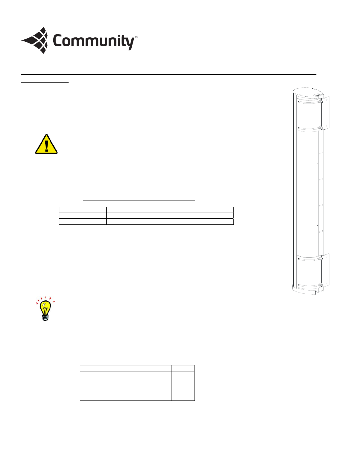
The ENTASYS Pan Bracket Kit, designated ENT-PB, can be used to mount up to five ENTASYS columns flush on
a wall while providing a means to rotate the entire array up to 80° (5° - 85° aiming angles) about a vertical
axis. The Pan Brackets may be installed o n a wall in either a left-hand or right-hand orientation as required for
the desired aiming of the array. The Pan Bracket Kit consists of two curved metal brackets and all of the
hardware required to attach these brackets to the T-Bar Mounting Bracket included with the ENTASYS Column
Line Array System.
WARNING: A pair of ENTASYS Pan Brackets must not be used to support more than five (5)
ENTASYS loudspeakers. Attempting to do so will exceed the Working Load Limit of the
bracket and could result in the failure of the bracket and potentially result in severe injury
and/or loss of life.
All parts in the kit are engineered to provide a high margin of safety when used in accordance with these
instructions. The brackets are manufactured of steel and are covered with a durable powder-coat finish. Kits
are available in either black or white to match the color of the enc losure.
Table 1: Pan Bracket Kit Part Numbers
Part No. Description
ENT-PB ENTASYS Pan Bracket Kit, Black
ENT-PBW ENTASYS Pan Bracket Kit, White
No hardware is provided to attach the ENTASYS column assembly and Pan Brackets to the mounting surface.
Such hardware must be supplied by the installer and should be sized and rated for the weight load of the
enclosures. The installer is solely responsible for determining if all rigging components that are used to mount
or suspend the enclosure(s) are adequately sized and rated, and if the structure they are mounted or
suspended from is capable of safely supporting the aggregate weight load. If multiple enclosures are
suspended one above the other, it is the installer’s responsibility to insure that the combined weight load does
not exceed the Working Load Limit of any one rigging fitting. This is particularly important if the enclosures are
steeply angled upward or downward, as most or all of the weight may be supported by the front or rear points
only.
NOTE: A single tall array of up to five (5) ENTASYS columns joined together by the ENTASYS Coupler Bracket(s)
may be mounted using a single Pan Bracket Kit. If multiple columns are t o be mounted using a Pan Bracket Kit,
purchase the ENTASYS Coupler Bracket (part number ENT-CB) and follow the instructions in the com p lete ENTASYS
Installation/Operation Manual included with each ENTASYS column loudspeaker.
For more information on using the ENTASYS Pan Bracket Kit, please refer to the complete ENTASYS
Installation/Operation Manual enclosed with each ENTASYS column.
Table 2: Pan Bracket Kit Parts List
Part Qty
Metal Pan Bracket 2
M6 x 25mm Flat Head Screws 8
6mm Flat Washer 8
6mm Lock Washer 8
M6 Hex Nuts 16
**The installer must supply all other hardware for the installation
Page 2
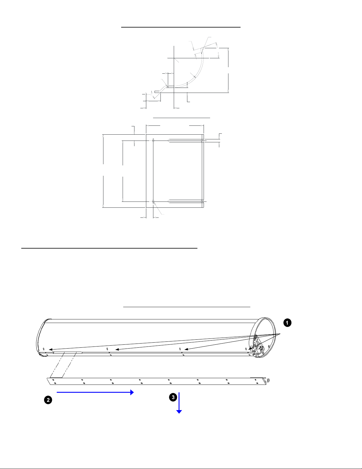
Figure 1: Metal Pan Bracket Dimensions
)
)
SLOT END
20°
4.329" [109.96]
SLOT END
45°
1.417" [36]
.591" [15]
2.716" [69]
.394" [10]
R2.874"
[R73]
.472" [12]
SECTION THRU SLOTS
.591" [15]
5.590" [142]
.276" [7] SLOT (TYP
7.087"
[180]
5.905"
[150]
.709" [18]
(2) .256" [6.5] D HOLES
ENTASYS Pan Bracket Kit Assembly Instructions
1. The ENTASYS T-Bar Mounting Bracket, sometimes referred to as the “T” Mounting Bracket, is included and shipped attached
to each ENTASYS column loudspeaker. Remove the T-Bar Mounting Bracket(s) from each ENTASYS column. This is most
easily accomplished by either laying the ENTASYS loudspea ker on its side or placing it upside down on a level surface.
There are eight set screws, four on each side of the rear of the enclosure, that secure this brack et to the enclos ure. Once
these are sufficiently loosened, the Mounting Bracket may be slid down parallel to the enclosure, as if pulling it away from
the bottom of the enclosure, approximately 3 inch es (75 mm). It can then be pulled out of the slot and away from the
enclosure.
Figure 2: T-Bar Mounting Bracket Removal
LooseneightSet
Screws
SlideMountingBracket3”(75mm
PullMountingBracket
awayfromloudspeaker
2. Securely fasten eight of the M6 bolts and nuts to the T-Bar Mounting Bracket using four in the uppermost portion of the TBar Mounting Bracket and four in the lowermost portion of the T-Bar Mounting Bracket. This will yield eight mounting studs
for the Pan Brackets. Do this before attaching either of the Pan Brackets or the washers to the T-Bar Mounting Bracket.
Page 3

(8) M6 x 25mm
FLAT HEAD SCREW
(8) 6mm FLAT WASHER
(8) 6mm LOCK WASHER
(16) M6 HEX NUT
"T" MOUNTING BRACKET
(EXISTING)
(2) PAN BRACKET
3. Attach one of the Pan Brackets to the uppermo st studs on the T-Bar Mounting Bracket and the other Pa n Bracket to the
lowermost studs on the T-Bar Mounting Bracket using the flat washers, lock washers, and remaining nuts. Tighten the nuts
securely.
4. Place the T-Bar Mounting Bracket and Pan Bracket assembly on the wall where the ENTASYS array is to be installed. Mark
the positions on the wall where the holes in the Pan Bracket are located.
5. Remove the T-Bar Mounting Bracket and Pan Bracket assembly fr o m the wall and properly prepare the wall to accept the
correct type of bolts with which to attach the Pan Bracket assembly to the wall.
6. Attach the T-Bar Mounting Bracket and Pan Bracket assembly to the wall using the proper bolts fo r the wall material and the
weight of the ENTASYS array to be mounted.
7. Loosen the eight M6 nuts between the Pan Bracke t and the wall (not the nuts between the T-Bar Mounting Bracket and the
Pan Bracket) and rotate the T-Bar Mounting Bracket to its approximate desired aiming location and retighten the nuts.
8. Align the tabs on the T-Bar Mounting Bracket with t he larger opening in the slot on the back of the ENTASYS enclosure.
Insert the T-Bar Mounting Bracket into the slot in the enclosure and slide the enclosure down onto the T-Bar Mounting
Bracket until it is resting on the Bottom Fitting. This is done by simply reversing the order of the steps for removing the
bracket as shown in Figure 2.
9. Tighten the eight M4 Set Screws on the ENTASYS enclosure to secure it to the T-Bar Mounting Bracke t.
10. When the enclosure is in position, the eight M6 nuts between the Pan Bracket and the wall may be loosened and the array
rotated in the Pan Bracket to the final desir ed aiming position. Once the array is aimed as desired, the eight M6 nuts must
be securely tightened to keep the array in position and have a safe mounting.
11. If multiple ENTASYS columns are to be mounted in an array with the Pan Bracket, first connect the individual T-Bar
Mounting Brackets using the appropriate number of ENTASYS Coupler Brackets (part number ENT-CB) and perform Step #6
by attaching the entire T-Bar Mounting Bracket and Pan Bracket assembly to the wall. Slide the individual ENTASYS
enclosures down onto the T-Bar Mounting Bracket as described in Step #8, starting with the lowermost enclosure. Make
sure the Bottom Fitting is securely fastened to the bottom of the T-Bar Mounting Bracket and Coupler Bracket
assembly with its M6 Set Screw. This is critical as the entire weight of the array must be supported by this
single Bottom Fitting. The upper enclosures will not rest on the Bottom Fitting, but instead will rest on the ENTASYS
enclosure directly below it. For more information on using the ENTASYS Coupler Bracket with the Pan Bracket Kit, please
refer to the complete ENTASYS Installation/Operation Manual enclosed with each ENTASYS column.
Figure 3: Pan Bracket Kit Assembly Diagram (One Column)
Page 4

Figure 4: Pan Bracket Kit Assembly Diagram (Two Columns)
R
(8) M6 x 25mm
FLAT HEAD SCREW
(8) 6mm FLAT WASHER
(8) 6mm LOCK WASHE
(16) M6 HEX NUT
(2) PAN BRAC KET
"T" MOUNTING BRACKET
(EXISTING)
ENT-CB
COUPLER BRACKET
Outdoor Installation Tip: Whenever
ENTASYS column loudspeakers are
installed outdoors, or exposed to direct
rain, water or precipitation, the
loudspeaker enclosure must be angled
downward at a minimum of two (2)
degrees.
WARNING: The bolts used and wall material into which the Pan Bracket assembly is bo lted m ust
be capable of supporting the load of the ENTASYS array to be mounted. It is the responsibility of
the installer to verify these items.
CAUTION: Installation of loudspeakers should only be performed by trained and qualified
personnel. It is strongly recommended that a l ic e nse d and c e rt ifie d professional structural
engineer approve the mounting design.
Community Professional Loudspeakers
333 East Fifth Street, Chester, PA 19013-4511 USA
Phone (610) 876-3400 · Fax (610) 874-0190
www.communitypro.com
23OCT2014
 Loading...