

Page 1
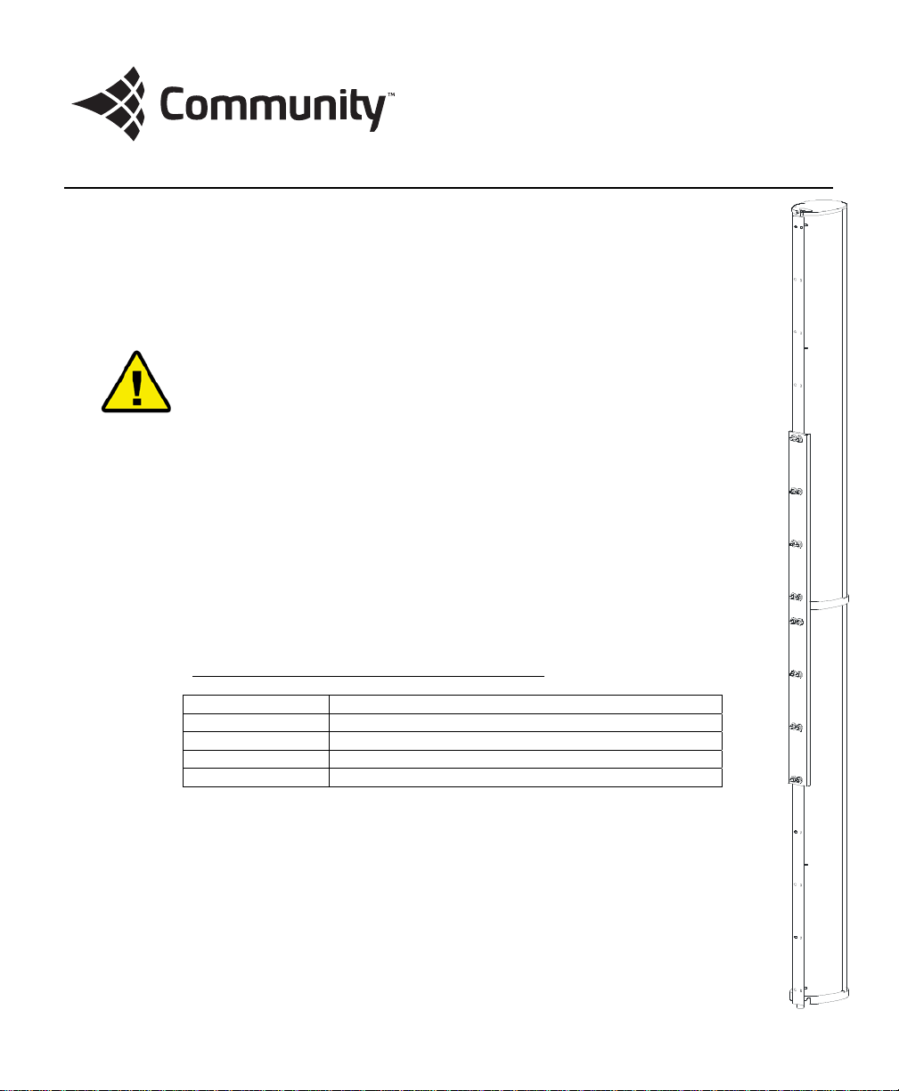
ENT-CB
ENTASYS Coupler Bracket
Coupler Bracket for Community’s ENTASYS Column Line Array System
The ENTASYS Coupler Bracket is used to attach two ENTA SYS columns together into a tall
assembly, before using the ENTASYS Pan Bracket, Combination Pan-Tilt Bracket or Fly Kit
Bracket for permanent mounting or suspension. Multiple Coupler Brackets may be used to
connect up to five columns together. Use two Coupler Brackets to join three ENTASYS columns
together, use three Coupler Brackets to join four ENTASYS columns together, or use four
Coupler Brackets to join five ENTASYS columns together.
A single Coupler Bracket must be attached to the two T-Bar Mounting Brackets from the two
ENTASYS columns that are to be connected together. Connecting the ENTASYS enclosures
together is the first step required when constructing multiple column arrays, regardless of the
other brackets that will be used to mount or susp end them.
All parts in the kit are engineered to provide a high margin of safety when used in accordance
with these instructions. The brackets are manufactured of steel and are covered with a durable
powder-coat finish. Kits are available in sets of one or two Coupler Brackets and in either black
or white to match the color of the enclosures.
No hardware is provided to attach the tall ENTASYS column assembly connected by a Coupler
Bracket(s) to the mounting surface. Such hardware must be supplied by the installer and
should be sized and rated for the weight load of the enclosures. The installer is solely
responsible for determining if all rigging components that are used to mount or suspend the
enclosure(s) are adequately sized and rated, and if the structure they are mounted or
suspended from is capable of safely supporting the aggregate weight load. If multiple
enclosures are suspended one above the other, it is the installer’s responsibility to insure that
the combined weight load does not exceed the Working Load Limit of any one rigging fitting.
This is particularly important if the enclosures are steeply angled upward or downward, as most
or all of the weight may be supported by the front or rear points only.
WARNING: Up to four (4) ENTASYS Coupler Brackets may be used to
connect up to five (5) ENTASYS loudspeakers together into a single array. Do
not attempt to construct a single array or more than five (5) ENTASYS
loudspeakers. Attempting to do so will exceed the Working Load Limit of the
bracket and could result in the failure of the bracket and potentially result in
severe injury and/or loss of life.
Table 1: Coupler Bracket Part Numbers
Part No. Description
ENT-CB1 ENTASYS Coupler Bracket, Qty 1, Black
ENT-CB1W ENTASYS Coupler Bracket, Qty 1, White
ENT-CB2 ENTASYS Coupler Bracket, Qty 2, Black
ENT-CB2W ENTASYS Coupler Bracket, Qty 2, White
Page 2
Part Qty
Coupler Bracket 1
M6 x 20mm Flat Head Screws 16
6mm Flat Washer 16
6mm Lock Washer 16
M6 Hex Nuts 16
**The installer must supply all other hardware for the installation
For more information on using the ENTASYS Co upler Bracket, please refer to the complete
ENTASYS Installation/Operation Manual enclosed with each ENTASYS column.
Table 2: ENTASYS Coupler Bracket Part List
ENTASYS Coupler Bracket Assembly Instructions
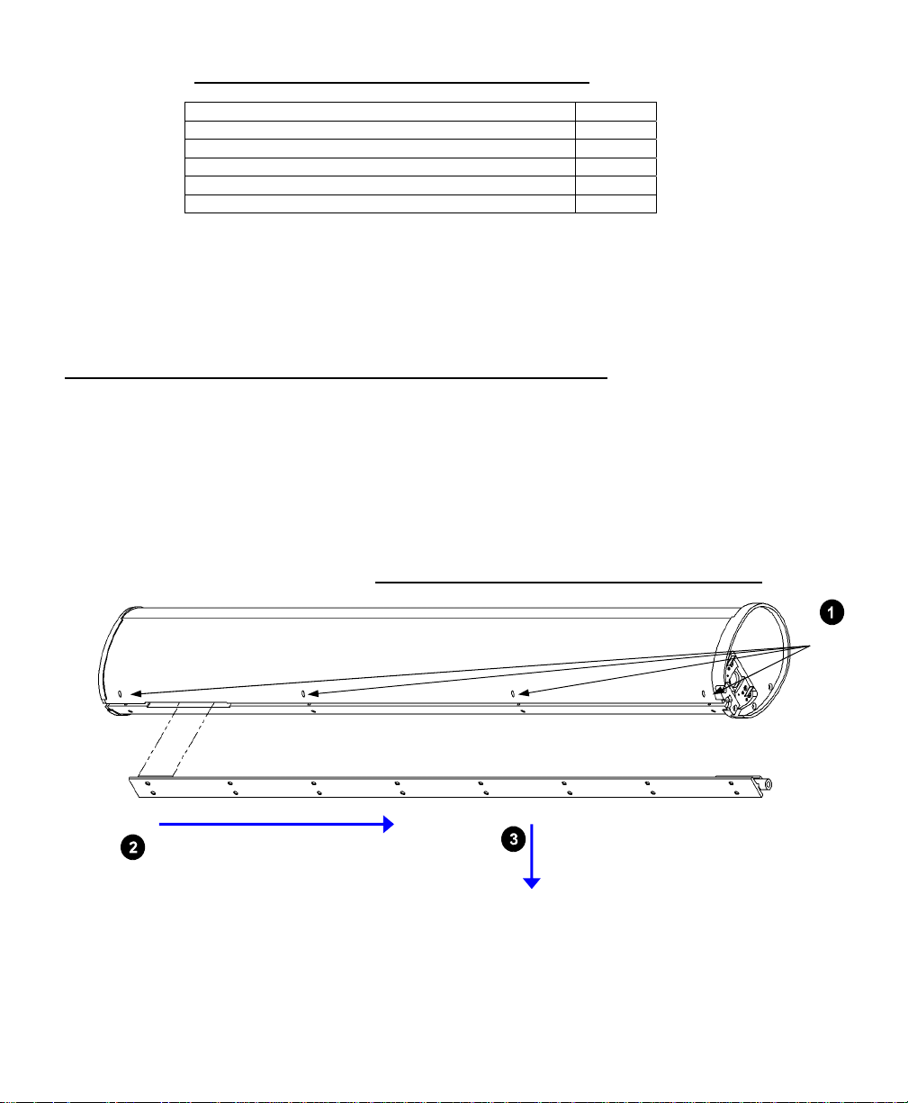
1. The ENTASYS T-Bar Mounting Bracket, sometimes referred to as the “T-bracket”, is included and
shipped attached to each ENTASYS column loudspeaker. Remove the T-Bar Mounting Brackets
from each ENTASYS column to be connected together. This is most eas ily acco mplished by either
laying the ENTASYS loudspeaker on its side or placing it upside down on a level surface. There
are eight set screws, four on each side of the rear of the enclosure, that secure this bracket to
the enclosure. Once these are sufficiently loosened, the Mounting Bracket may be slid down
parallel to the enclosure, as if pulling it away from the bottom of the enclosure, approximately 3
inches (75 mm). It can then be pulled out of the slot and away from the enclosure.
Figure 1: T-Bar Mounting Bracket Removal
Slide Mounting Bracket 3” (75 mm)
Pull Mounting Bracket away
from loudspeaker
2. Bolt the Coupler Bracket to the two T-Bar Mounting Brackets using the M6 x 20mm bolts, flat
washers, lock washers, and nuts included with the Coupler Bracket. Note that the T-Bar Mounting
Brackets should lay inside the “U” shape profile of the Coupler Bracket. Verify that the nuts and
bolts are securely tightened. Failure to do this may result in unsafe construction of the array.
Loosen
Eight Set
Screws
Page 3

3. If more than two ENTASYS columns are to be connected together, repeat Step 2 as necessary for
connecting up to five T-Bar Mounting Brackets together.
4. Stack the ENTASYS columns together in the required order for the array to be constructed. This
may be done vertically by stacking them on top of each other, or horizontally by laying them on
the ground.
5. Align the tabs on the T-Bar Mounting Brackets w ith the larger opening in the slot on the back of
each ENTASYS enclosure. Insert the T-Bar Mounting Bracket and Coupler Brack et assembly into
the slot in the enclosure and slide the T-Bar Mounting Bracket and Coupler Bracket assembly up
into position in the enclosure slot. This is done by simply reversing the order of the steps for
removing the bracket as shown in Figure 1.
6. Make sure the Botto m Fitting is securely fastened to the bottom of the T-Bar Mo unting
Bracket and Coupler Bracket assembly with its M6 Set Screw. This is critical as the
entire weight of the array must be supported by this single Bottom Fitting.
7. Tighten all eight of the M4 Set Screws in each ENTASYS enclosure to secure it to its T-Bar
Mounting Bracket.
Assembly Tip: Use a C-clamp of locking pliers (vise-grips) to align the ends for the two
T-Bar Mounting Brackets before bolting them to the Coupler Bracket. Leave the clamp in
place until all of the screws have been tightened. This will assure proper alignment.
Outdoor Installation Tip: Whenever ENTASYS column loudspeakers are installed
outdoors, or exposed to direct rain, water or precipitation, the loudspeaker enclosure
must be angled downward at a minimum of two (2) degrees.
WARNING: The screws used and wall material onto which the tall
ENTASYS array assembly is mounted or suspended must be capable of
supporting the load of the ENTASYS assembly. It is the responsibility of
the installer to verify these items.
CAUTION: Installation of loudspeakers should only be performed by
trained and qualified personnel. It is strongly recommended that a
licensed and certified professional structural engineer approve the
mounting design.
Page 4

Figure 2: Coupler Bracket Assembly Diagram
T- BAR M OUNTI NG BRACKET
(16) M6 x 20mm
FLAT HEAD SCREW
(16) 6mm FLAT WASHER
(16) 6mm LOCK WASHER
(16) M6 HEX NUTS
COUPLER BRACKET
T-BAR MOUNTING BRACKET
Community Professional Loudspeakers, 333 East Fifth Street, Chester, PA 19013 USA
Phone (610) 876-3400 · Fax (610) 874-0190 · www.communitypro.com
ENT-CB OM 23OCT2014
 Loading...