

Page 1
Distributed Design Series
DP6 and DP8 Pendant Loudspeaker
Installation Guide
CAUTION: Installation of DP6 and DP8 loudspeakers should
only be performed by trained and qualied personnel. It is
strongly recommended that a licensed and certied professional
structural engineer approve the mounting. Severe injury and/or
loss of life may occur if this product is improperly installed.
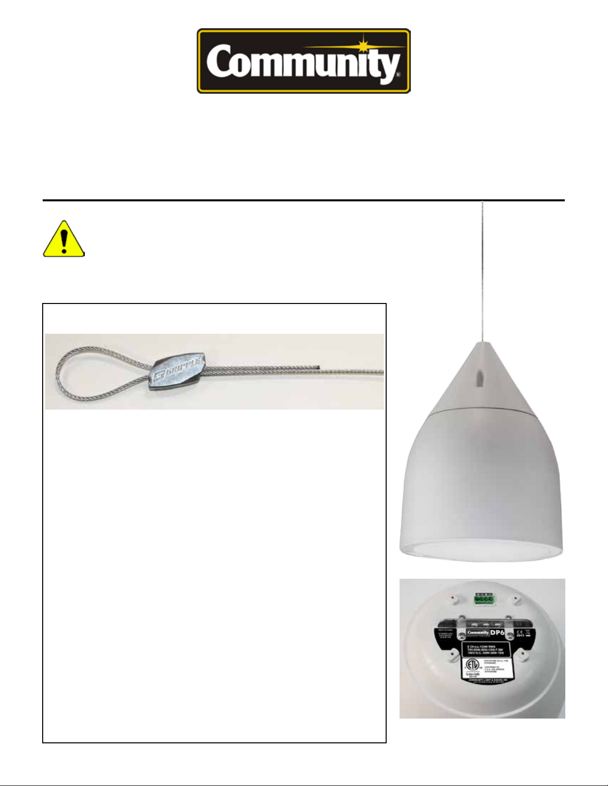
Gripple® Manufacturer’s Recommendations and Important Notes
™
Gripple manufactures the speed clamps provided with this product. To ensure
maximum safety, it is essential to follow their recommendations as listed below.
• For indoor use in a dry environment.
• Do not apply lubricant to any part of the assembly as this will alter the surface
of the cable, attracting dirt and debris to adhere and possibly reducing the load
capacity due to lubricant-induced slippage.
• Do not use on lifting applications; for static loads only.
• Do not use for loads outside the stated range of the product. The Gripple
wedges work by using the weight of the load to draw the wedge into the cable,
creating a secure grip. If used with too light a load, the wedge may not be able
to securely grip the cable.
• Do not exceed the Safe Working Load (SWL) of the product. Each product is
load rated and incorporates a minimum safety factor of 5:1. The SWL takes into
account the specication criteria of the Gripple, the cable and the pressed ferule.
• The #2 Gripple products supplied have the suitable minimum load and
the maximum SWL specications to be used with Community’s pendant
loudspeakers.
• Do not use on coated wire rope. Prior to assembly, it is essential to strip off
any coating on the length of cable to be inserted into the Gripple. It is important
to maintain the metal-to-metal contact between the locking wedges in the Gripple
and the cable.
• When applying paint or other coating, ensure that a dedicated Gripple decor
cover is used to cover the Gripple. This will ensure that the movement of the
locking wedges inside the assembly is not impaired. After painting, the Gripple
should not be repositioned on the cable.
• Do not use standard zinc galvanized Gripple products in chlorinated
environments. Use only Stainless Steel Gripple products in these environments.
Suspension bracket and input jack detail
Page 2
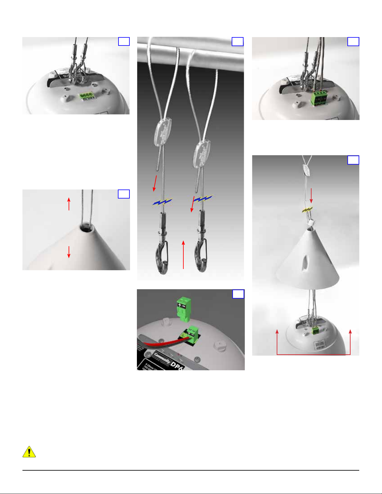
Hanging and Connecting the Loudspeaker
1
Before inserting cables into the Gripples, attach
both snap hooks to the suspension bracket atop
the loudspeaker as shown in Figure 1. The main
cable attaches to the center hole, and the safety
cable to either of the two outer holes depending
on the desired orientation. Make sure the springloaded safety catch is positioned as shown so it
closes the loop to prevent accidental detachment.
Note: Two 15-foot cable kits with Gripple Speed
Clamps are included; longer kits are available as
noted under the Optional Accessories section.
Plain Cable Ends
2
D
A
E
B
3
Insert the Euroblock plug(s) into the jack atop the
loudspeaker as shown in Figure 5. No jumper is
necessary because the pairs of conductors in the
Euroblock jack are internally connected to pass
the signal through.
B
5
6
Snap-Hook Ends
Thread the plain ends of the main cable and
safety cable up through the loudspeaker top
cover as shown in Figure 2.
For clarity in Figure 3 the loudspeaker and its
cover are not shown, but these should actually
be in place per Figures 1 and 2. Refer to Figure 3
for the following steps:
A. Beginning with the main support cable, insert
its plain end through the Gripple Speed Clamp.
Loop the cable over (or through) the ceiling
anchor point, thread the plain end back through
the Gripple and pull that cable end so that the
loop is hanging a little lower than where you think
you’ll want the loudspeaker’s attachment point to
be located.
B. Repeat this with the safety cable and Gripple,
looping the cable over or through an independent
attachment point.
C. Support the loudspeaker with your hand at the
desired height.
D. Pull the end of the main cable to take up any
slack.
E.
Pull the end of the safety cable to take up any
slack. See Figure 6 for further height adjustments.
CAUTION: Do NOT pull the cables to
raise the loudspeaker.
C
4
Two 2-pole Euroblock plugs are supplied with
the pendant loudspeaker and connect to a
jack on the top of the loudspeaker as shown in
Figure 4. Thread the audio cable down through
the loudspeaker top cover, and then strip
approximately 1/4-inch (4mm) of insulation from
the cable’s inner wire conductors. Insert the wire
ends into the Euroblock plug terminals using
the proper polarity (marked on plugs and jack).
If you daisy chain an audio cable to the next
loudspeaker, bring it through the top cover as
well and connect that second cable’s wire pair
to the other Euroblock plug. Secure all wires by
tightening the screws in the end of the Euroblock
plugs.
A
Adjust the loudspeaker height as necessary.
A. Lift and support the loudspeaker with one
hand.
B. Pull the main support cable end to take up the
slack. The split cover plug is not yet pressed into
position in this photo.
The Gripple Speed Clamp automatically tightens
from the cable tension when you allow the
loudspeaker to hang. Test by gradually lowering
your hand. Don’t just “drop” the loudspeaker.
When you have the proper height set, then take
up the slack on the safety cable by pulling its free
end. Since the loudspeaker is already held by the
main cable it isn’t necessary to support it while
doing this.
A
Distributed Design Series - DP6 / DP8 Installation Guide Page 2
Page 3

Note: It is best to begin with the loudspeaker
lower than the anticipated nal height, and lift
it into position. It can be lowered later by using
the Gripple Setting Key, as shown in Figure 7,
but best practice is to set the height primarily by
raising the unit.
7
A
B
To lower a loudspeaker which is already clamped
by the Gripple, refer to Figure 7.
A. Insert the setting key into the small hole in the
bottom of the Gripple, which forces the internal
locking wedges open, and then,
B. Slide the cables to lower the loudspeaker.
Use this method rst to create some extra slack
in the safety cable, then support the loudspeaker
with your hand as you pull the main support
cable, lowering the loudspeaker to the desired
height. Finally remove the setting key to lock the
loudspeaker in place, and re-tension the safety
cable by pulling the loose end until it is snug.
8
C
B
A
For extra weatherproong, apply a small bead
of silicon sealant around the ridge on the
loudspeaker body where the top will join it (Figure
8A). Slide the loudspeaker cover into position
so its four recessed holes align with the four
threaded ttings on the top of the loudspeaker
(Figure 8B). Then insert the four provided
machine screws and fasten the cover. Finally,
press the split cover plug into place (Figure 8C).
Also apply some silicon sealant on the inside and
outside surfaces of the split cover plug before
installing.
If you have purchased the optional PST-14
Decorative Plastic Tubing, this is an appropriate
time to install it.
Loudspeaker Tap Setting
9
To gain access to the tap switch (inset above),
remove the loudspeaker grille by lifting the
strapping tape attached on either side of the
grille. Once the grille is off, remove the tape and
set the tap switch to the appropriate tap setting.
CAUTION: Do NOT change the setting
on the tap switch while the loudspeaker
is in use. Turn off the power amplier
before adjusting this switch.
The tap switch is located on the front bafe
adjacent to the loudspeaker cone (red arrows
and inset in Figure 9, yellow arrow in Figure 10).
You can use a standard #2 or #3 Phillips or a
medium slot-blade screwdriver (not the one
provided with the loudspeaker kit), or just press
Painting the Loudspeaker
These loudspeakers are easy to paint. It’s best to
paint the bafe and enclosure before installation.
Type of Paint
The loudspeaker’s ABS plastic bafe and
enclosure accept almost any type of latex
or oil-based paint. A two-coat application is
recommended.
Caution: When applying paint or other
coating, ensure that a dedicated
Gripple decor cover is used to cover
the Gripple. This will ensure that the movement
of the locking wedges inside the assembly is
not impaired. After painting, the Gripple
should not be repositioned on the cable.
Caution: Use only light mineral
spirits thinner as a cleaner. NEVER
use gasoline, kerosene, acetone,
methyl ethyl ketone (MEK), paint thinner,
harsh detergents or other chemicals as they
may permanently damage the loudspeaker.
Some of these chemicals are also toxic and
highly ammable.
Painting Process
To obtain the best results follow this procedure:
1. Clean the bafe and enclosure with a light
solvent such as mineral spirits, rubbing with a
10
with your thumb rmly, and twist to adjust
the power control dial on the front face of the
loudspeaker bafe. As shown in Figure 9, you
can make any of ve different settings, although
the dial has dual calibrations so at rst glance
it appears to have ten settings. The 8-ohm
position is the same on both sides and is for a
low impedance connection. On the lower-left side
of the power tap control shown in the close-up
on Figure 8 are the power values for 100-volt
connections, and on the upper right side are the
power values for 70-volt connections.
Note: The letters NC mean “no-connect” but they
do not actually break a connection. DO NOT USE
this setting if you’re using a 100-volt distribution
scheme as the loudspeaker may draw excessive
power; it corresponds to the highest power that
can be drawn with a 70-volt source.
This control makes it very easy and fast to
balance an installation since there is no need
to open the loudspeakers and move wires to
different terminals. Just be sure there is no
applied signal when you are actually changing
the tap switch setting. When the desired setting
is conrmed, replace the grille.
lightly dampened cloth. Do not use abrasives
such as sandpaper or steel wool.
2. Mask the loudspeaker so that the surround,
cone and center area will not receive any paint.
Use a low-tack painter’s tape (typically blue
in color) to avoid damaging the loudspeaker
surround when the tape is removed. We advise
against using conventional masking tape and
NEVER use duct tape in this application; these
kinds of tape generally leave adhesive residue
that can be difcult to remove and that may
actually cause damage.
After cleaning, apply two or more two thin coats
of either latex or oil-based paints. Latex paint will
adhere better if an oil-based primer is used rst.
Apply the paint with a roller or brush, or spray
it on.
The grille should be painted separately, and when
it is not in place on the loudspeaker. We further
recommend that you remove the grille’s internal
cloth mesh, then spray paint the grille assembly.
Avoid using a roller or brush to paint the grille as
its metal perforated holes may become clogged
with paint, which degrades sound quality and
also may attenuate the sound. Reinstall the
internal cloth mesh (or if damaged install a new
cloth mesh).
Distributed Design Series - DP6 / DP8 Installation Guide Page 3
Page 4
Optional Accessories
Various “Cable Hang Kits” are available. Each includes a zinc galvanized steel rigging cable with locking
end loop and a stainless steel Gripple Speed Clamp. Included with your pendant loudspeaker are two
model PHK-15 kits that have 15-foot (4.6 meter) cables.
Optional accessories include:
• PHK-30: 30-foot (9.1 meter) cable
• PHK-50: 50-foot (15.2 meter) cable
• PSC: Replacement Gripple Speed Clamp
• PST-14: Decorative (split plastic) tubing to dress the hanger cables and electrical wiring. PST-14
tubing is 14 feet (4.3 meters) long and may be trimmed.
Specications
Model
DP6
DP8
Sensitivity
(1 watt, 1m)
DP6 94 dB SPL 65 Hz - 22 kHz
DP8 95 dB SPL 60 Hz - 22 kHz
Cone Size Dimensions Weight
6.5 inches
(165 mm)
8.0 inches
(203 mm)
Operating
Range
Safety Agency Compliance
Conforms to UL1480 Standard
Certied to CSA C22.2 No. 60065 Standard
14.73 inches (374 mm) enclosure height
11.22 inches (
17.72 inches (450 mm) enclosure height
13.41 inches (
8Ω/7.5/15/30/60 (70V input)
8Ω/15/30/60/NC (100V input)
8Ω/15/30/60/120 (70V input)
8Ω/30/60/120/NC (100V input)
285 mm) face diameter
341 mm) face diameter
Tap Switch Settings Power Rating
11.8 lbs
(5.4 kg)
16.5 lbs
(7.5 kg)
100W RMS 250W PGM
150W RMS 375W PGM
Cable kits with Gripple ® speed clamps meet the following standards:
UL 1598 Luminaire Fittings and
UL 2239 Conduit and Cable Support Hardware.
CSA listing for Class 3426-01 (Canada) and
Class 3426-81 (U.S.A.) Luminair Fittings.
4001450
DIN 4102-2
Distributed Design Series - DP6 / DP8 Installation Guide Page 4
Page 5

Important Safety Instructions
Always follow these basic safety precautions
when using or installing Distributed Design
Pendant Mount loudspeakers and accessories:
• Read these instructions.
• Keep these instructions.
• Heed all warnings.
• Follow all instructions, particularly those
pertaining to rigging, mounting, hanging and
electrical connections.
• Do not use this apparatus near water.
• Clean only with dry cloth.
• Do not block any ventilation openings. Install
in accordance with the manufacturer’s
instruction.
• Do not install near any heat sources such
as radiators, heat registers, stoves, or other
apparatus (including ampliers) that produce
heat.
• Only use attachments/accessories that are
specied and approved by the manufacturer.
• Refer all servicing to qualied service
personnel. Servicing is required when
the apparatus has been damaged in any
way, such as power-supply cord or plug is
damaged, liquid has been spilled or objects
have fallen into the apparatus, the apparatus
has been exposed to rain or moisture, does
not operate normally, or has been dropped.
The terms caution, warning, and danger may be
used in this manual to alert the reader to important
safety considerations. If you have any questions
or do not understand the meaning of these terms,
do not proceed with installation. Contact your
local dealer, distributor, or call Community directly
for assistance. These terms are dened below:
CAUTION: describes an operating condition or
user action that may expose the equipment or
user to potential damage or danger.
WARNING: describes an operating condition
or user action that will likely cause damage to
the equipment or injury to the user or to others
in the vicinity.
DANGER: describes an operating condition or
user action that will immediately damage the
equipment and/or be extremely dangerous or
life threatening to the user or to others in the
vicinity.
WARNING: To reduce the risk of re or
electric shock, do not expose this
apparatus to rain or moisture.
These servicing instructions are for use by
qualied service personnel only. To reduce
the risk of re or electric shock do not perform
any servicing other than that contained in the
operating instructions unless you are qualied to
do so.
The loudspeakers described in this manual
are designed to be ‘own’ or suspended for
maximum acoustical performance using a
variety of rigging hardware, means, and methods
in some applications. It is essential that all
installation work involving the suspension of
these loudspeaker products be performed
by competent, knowledgeable persons who
understand safe rigging practices. Severe injury
and/or loss of life may occur if these products are
improperly installed. Please read the section on
wiring and installation for additional information.
L’information de Sûreté Importante
PRÉCAUTION : Veuillez toujours suivent ces
mesures de sécurité de base lors de l’utilisation
ou lors de l’installation des haut-parleurs
Distributed Design Séries Pendant Mount et de
ces accessoires :
• Lisez et Gardez les instructions.
• Observez tous les avertissements.
• Suivez toutes les instructions, particulièrement
ceux concernant le calage, support, montage
et raccordements électriques.
• Ne pas utiliser cet appareil près de l’eau.
• Nettoyez seulement avec un tissu sec.
• Ne pas bloquer les ouvertures de ventilation.
Installer conformément aux instructions du
fabricant.
• Ne pas installer près des sources de chaleur
comme les radiateurs, les cuisinières,
foyers ou autres appareils (y compris les
amplicateurs) qui peuvent produire de la
chaleur.
• Utilisez seulement les accessoires qui sont
spéciés et approuvés par le fabricant.
• Référez tout entretient au personnel qualié
de service. Ceci est exigé quand l’appareil a
été endommagé de quelque façon, incluant
le l d’alimentation et ou l’embout du l a été
endommagé, des liquides ont été renversés
ou des objets sont tombé à l’intérieur de
l’appareil, l’appareil a été exposé à la pluie
ou l’humidité, l’appareil ne fonctionne pas
normalement ou a été échappé.
Les termes attention, avertissement, et danger
peut être utilises dans ce manuel pour alerter le
lecteur aux considérations importantes de sûreté.
Si vous avez des questions ou ne comprenez
pas la signication de ces termes, ne procédez
pas à l’installation. Contactez votre détaillant,
distributeur, ou Community directement pour
assistance. Les termes sont dénies ci-dessous:
ATTENTION : décrit une condition de
fonctionnement ou une action d’utilisateur qui
peuvent exposer l’équipement ou l’utilisateur
aux dommages potentiels ou au danger.
AVERTISSEMENT : décrit une condition de
fonctionnement ou une action d’utilisateur qui
peuvent causer des dommages probable à
l’équipement et/ou à l’utilisateur et à ceux se
trouvant à proximité.
DANGER : décrit une condition de
fonctionnement ou une action d’utilisateur qui
endommageront immédiatement l’équipement
et/ou seront extrêmement dangereuses et
qui peut représenter un danger pour la vie à
l’utilisateur et à ceux se trouvant à proximité.
AVERTISSEMENT : Pour réduire le
risque de feu ou de décharge électrique,
ne pas exposer cet appareil à la pluie ou
l’humidité.
Ces instructions d’entretient sont pour l’usage
d’un personnel de service qualié seulement.
Pour réduire le risque de feu ou de décharge
électrique n’exécutez aucun entretient autrement
que ce qui est contenu dans les instructions
d’opérations à moins que vous êtes qualié pour
le faire.
Les haut-parleurs décrits en ce manuel sont
conçus pour être accroché ou suspendus an
d’atteindre une exécution acoustique maximum
en utilisant une série de différents matériaux,
moyens, et méthodes de calage dans certaines
applications. Il est essentiel que tout le travail
d’installation impliquant la suspension de ces
produits de haut-parleur soit effectué de façon
sécuritaire par des personnes compétentes
et bien formées dans les méthodes de calage.
Des blessures graves et/ou des pertes
humaines peuvent se produire si ces produits
sont incorrectement installés. Veuillez lire la
section sur le câblage et l’installation pour des
informations supplémentaires.
Distributed Design Series - DP6 / DP8 Installation Guide Page 5
Page 6

Warranty Information and Service
TRANSFERABLE WARRANTY “(LIMITED)”
VALID IN THE USA ONLY
The Distributed Design Series Loudspeaker
Systems are designed and backed by
Community Professional Loudspeakers.
For complete warranty information within
the USA please refer to the Warranty
Card enclosed with the product. Please
call 610-876-3400 to locate your nearest
Authorized Field Service Station.
For Factory Service call 610-876-3400. You
must obtain a Return Authorization (R/A)
number prior to the return of your product
for factory service.
WARRANTY INFORMATION AND SERVICE
FOR COUNTRIES OTHER THAN THE USA
To obtain specic warranty information and
available ser vice locations fo r countries other
than the United States of America, contact
the authorized Community Distributor for
your specic country or region.
SHIPPING DAMAGE
If the product is damaged during transit
you must le a damage claim directly with
the freight company. Be sure to save the
carton and packing materials, as damage
claims can be denied if these materials
are not retained. If evidence of physical
damage exists upon arrival, be cautious
before signing a delivery acceptance
receipt. Often, the ne print will waive your
right to le a claim for damage or loss after
you sign it. Make sure that the number of
cartons shown on the freight documents
have actually been delivered.
FIND THE LATEST ONLINE
The latest version of this manual and
the most recent product information is
always available at Community’s website:
http://www.communitypro.com.
Community Professional Loudspeakers
333 East Fifth Street, Chester, PA 19013-4511 USA
Phone: (610) 876-3400 ∙ Fax: (610) 874-0190
www.communitypro.com
Copyright ©2013 Community Professional Loudspeakers
All Rights Reserved.
v: 10OCT2013
Distributed Design Series - DP6 / DP8 Installation Guide Page 6
 Loading...