

Page 1
VERIS Series
VERsatile Installation Systems
Exquisite Performance… Exceptional Value
Operation Manual
Page 2

EC STATEMENT OF CONFORMITY
This document confirms that the range of products of Community Professional Loudspeakers bearing
the CE label meet all of the requirements in the EMC directive 89/336/EEC laid down by the Member
States Council for adjustment of legal requirements. Furthermore, the products comply with the rules
and regulations referring to the electromagnetic compatibility of devices from 30-August-1995.
The Community Professional Loudspeaker products bearing the CE label comply with the following
harmonized or national standards:
DIN EN 55013:08-1991
DIN EN 55020:05-1995
DIN EN 55082-1:03-1993
The authorized declaration and compatibility certification resides with the manufacturer and can be
viewed upon request. The responsible manufacturer is the company:
Community Light & Sound
333 East 5
Chester, PA 19013
USA
TEL: 1-610 876-3400
FAX: 1-610 874-0190
Chester, PA USA February 2007
th
Street
Community VERIS Series - Operation and Installation Manual - Page 2
Page 3

TABLE OF CONTENTS
Table of Figures .......................................................................................................... 4
C-Tips ....................................................................................................................... 4
Important Safety Information ....................................................................................... 5
Precautions & Safety Considerations .............................................................................. 6
Introduction ............................................................................................................... 7
VERIS Technology ....................................................................................................... 7
Unpacking and Inspection ............................................................................................ 8
VERIS Specifications .................................................................................................... 9
Getting Acquainted ..................................................................................................... 11
PHYSICAL FEATURES OF VERIS FULL-RANGE MODELS .................................................................... 11
PHYSICAL FEATURES OF VERIS SUBWOOFERS .............................................................................. 12
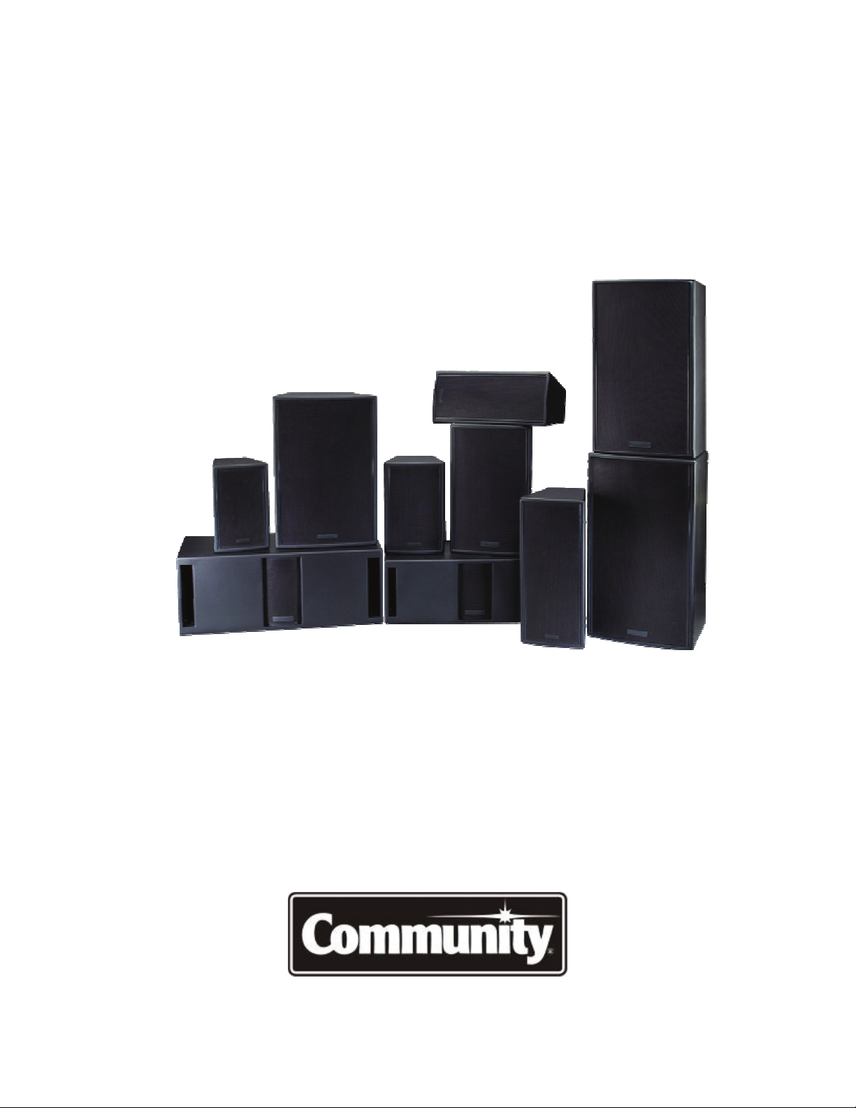
General Description .................................................................................................... 13
DYNA-TECHTM Driver Protection System ......................................................................... 13
Cool-Coil™ Technology ............................................................................................... 14
High-Pass Filters ........................................................................................................ 15
Connecting the Amplifier to the Loudspeaker.................................................................. 16
PIN DESIGNATIONS ............................................................................................................. 16
USING POWER TAPS ............................................................................................................ 17
70.7V AND 100V SYSTEMS ................................................................................................... 18
WIRING NEUTRIK TYPE CONNECTORS ........................................................................................ 18
KNOW YOUR AMPLIFIER ........................................................................................................ 19
CHOOSING LOUDSPEAKER WIRE .............................................................................................. 19
CONDUCTORS AND INSULATION .............................................................................................. 20
THE EFFECT OF WIRE GAUGE ON DAMPING FACTOR ...................................................................... 21
SELECTING AMPLIFIERS ........................................................................................................ 21
VERIS Applications ..................................................................................................... 22
Positioning Subwoofers ............................................................................................... 23
POLARITY ......................................................................................................................... 24
Choosing the Right Loudspeakers and Electronics ........................................................... 26
COMMISSIONING THE SYSTEM ................................................................................................ 26
FOR MORE INFORMATION AND APPLICATIONS ASSISTANCE .............................................................. 27
Rigging / Suspension and Safety .................................................................................. 27
IMPORTANT NOTES ON RIGGING LOUDSPEAKERS .......................................................................... 27
VERIS Mounting Brackets and Accessories ..................................................................... 28
Troubleshooting Guide ................................................................................................ 30
Technical Drawings .................................................................................................... 31
VERIS 6 ........................................................................................................................... 31
VERIS 8 ........................................................................................................................... 32
VERIS 26 ......................................................................................................................... 33
VERIS 28 ......................................................................................................................... 34
VERIS 12 ......................................................................................................................... 35
VERIS 15 ......................................................................................................................... 36
VERIS 32 ......................................................................................................................... 37
VERIS 35 ......................................................................................................................... 38
Community VERIS Series - Operation and Installation Manual - Page 3
Page 4
V
ERIS 210S ..................................................................................................................... 39
VERIS 212S ..................................................................................................................... 40
Servicing VERIS Loudspeakers ..................................................................................... 41
Warranty Information and Service ................................................................................ 41
TRANSFERABLE WARRANTY "(LIMITED)” VALID IN THE USA ONLY ...................................................... 41
OBTAINING WARRANTY SERVICE ............................................................................................. 41
WARRANTY INFORMATION AND SERVICE FOR COUNTRIES OTHER THAN THE USA .................................... 42
Summing Things Up ................................................................................................... 42
TABLE OF FIGURES
Following is a list of figures found in this manual:
Figure Title Page
1 Physical Features of a Typical VERIS Full-Range Model 10
2 Physical Features of a Typical VERIS Subwoofer 11
3 Community’s Cool-Coil™ Heat Evacuation System 14
4 VERIS Input Panel 15
5 VERIS Input Panel (Optional Autoformer Version) 16
6 NL4-Type Connector 17
7 Effect of Boundary Surfaces on Power Output 22
C-TIPS
Occasionally, in this manual, you’ll come across some useful tips that are intended to help
you get the most from your use of VERIS loudspeakers in portable applications and fixed
installations. We call these C-TIPS (short for COMMUNITY-TIPS or COOL-TIPS…we’ll let
you decide!). These tips originate from Community staff members as well as from installers
and end users. We welcome any C-TIPS that you may want to share with us, and we’ll
acknowledge you as the source if we print them in future user’s manuals.
Notice: Every effort has been made to insure that
the information contained in this manual was complete
and accurate at the time of printing. However, due to
ongoing technical advances, changes or modifications
may have occurred that are not covered in this manual.
Community VERIS Series - Operation and Installation Manual - Page 4
Page 5

IMPORTANT SAFETY INFORMATION
Always follow these basic safety precautions when using or installing VERIS loudspeakers
and accessories:
1. Read these instructions.
2. Keep these instructions.
3. Heed all warnings.
4. Follow all instructions, particularly those pertaining to rigging, mounting,
hanging and electrical connections.
5. Only use accessories that are specified and approved by the manufacturer.
The terms CAUTION, WARNING, and DANGER are used throughout this manual to alert
the reader to important safety considerations. If you have any questions or do not
understand the meaning of these terms, do not proceed with installation. Contact your
local dealer, distributor, or call Community directly for assistance. These terms are defined
below:
CAUTION: describes an operating condition or user action that may expose the equipment
or user to potential damage or danger.
WARNING: describes an operating condition or user action that will likely cause damage to
the equipment or injury to the user or to others in the vicinity.
DANGER: describes an operating condition or user action that will immediately damage the
equipment and/or be extremely dangerous or life threatening to the user or to others in the
vicinity.
Installation of loudspeakers should only be performed by trained and qualified personnel. It is strongly
recommended that a licensed and certified professional structural engineer approve the mounting design.
Community VERIS Series - Operation and Installation Manual - Page 5
Page 6

PRECAUTIONS & SAFETY CONSIDERATIONS
English
The loudspeakers described in this manual are designed and intended to be ‘flown’ or
suspended for maximum acoustical performance using a variety of rigging hardware,
means, and methods. It is essential that all installation work involving the suspension of
these loudspeaker products be performed by competent, knowledgeable persons who
understand safe rigging practices. Severe injury and/or loss of life may occur if these
products are improperly installed. Please read the section on rigging for additional
information.
Français
Les haut-parleurs décrits dans ce manuel sont conçus et sont projetés pour être ‘volé’ ou
suspendu pour l'exécution acoustique maximum utilisant une assortiment d'équiper
matériel, les moyens, et les méthodes. C'est essentiel que tout travail d'installation ait
impliqué la suspension de ces produits d'haut-parleur est exécutée par les personnes
compétentes et entraînées qui comprennent équiper les pratiques sûres. La perte sévère
de et/ou de blessure de vie peut arriver si ces produits sont incorrectement installés. S'il
vous plaît lire la section d'équiper pour l'information supplémentaire.
Deutsch
Die Lautsprecher, die in diesem Handbuch beschrieben werden, sind entworfen und sind zu
sein ‘geflogen' vorgehabt oder sind für maximale hörbare Leistung verschiedene
Manipulierenhardware, Mittel, und Methoden suspendiert benutzend. Es ist wesentlich,
dass alle Installationarbeit, die die Aufhängung von diesen Lautsprechernprodukten
verwickelt, von fähigen, ausgebildeten Personen durchgeführt werde, die sichere
Manipulierenpraxis verstehen. Schwere Verletzung bzw. Verlust des Lebens können
stattfinden, wenn diese Produkte unrichtig installiert sind. Bitte lesen Sie den Abschnitt
über Manipulieren für zusätzliche Informationen.
Italiano
Gli altoparlanti descritti in questo manuale sono disegnati e sono intesi essere ‘volato' o
sospeso per la prestazione massima acustica usando una varietà di attrezzare di hardware,
i mezzi, ed i metodi. È essenziale che tutta il lavoro di installazione coinvolgendo la
sospensione di questi prodotti di altoparlante è eseguita da dalle persone competenti,
addestrate che capisce le pratiche di attrezzare di cassaforte. La lesione severe e/o la
perdita di vita possono accadere se questi prodotti sono erratamente installati. Per favore
di leggere la sezione di attrezzare per le ulteriori informazioni.
Español
Los altavoces descritos en este manual se diseñan y son pensados ser ‘volado' o suspendido
para el desempeño acústico máximo que utiliza una variedad de aparejar hardware, de
medios, y de los métodos. Es esencial que todo trabajo de la instalación que implique la
suspensión de estos productos del altavoz sea realizado por personas competentes y
entrenada que entienden aparejar seguro las prácticas. La herida y/o la pérdida severas de
la vida pueden ocurrir si estos productos se instalan impropiamente. Lea por favor la
sección a aparejar para la información adicional.
Installation of loudspeakers should only be performed by trained and qualified personnel. It is strongly
recommended that a licensed and certified professional structural engineer approve the mounting design.
Community VERIS Series - Operation and Installation Manual - Page 6
Page 7

VERIS SERIES
OPERATION MANUAL
INTRODUCTION
Thank you for selecting Community’s VERIS Series. VERIS is a stunning collection of
affordable loudspeakers designed for permanent installation in venues such as nightclubs,
cafes, discotheques, houses of worship, auditoriums, lecture halls, restaurants, theatres,
and most anywhere else that people gather to enjoy music and hear the spoken word.
VERIS excels in applications requiring controlled coverage patterns, high-impact power
response, and intelligible sonic output.
VERIS loudspeakers are flexible, easy to install and use, and most importantly they provide
excellent sound quality.
This Operation Manual is intended to help you install VERIS loudspeakers effectively and
safely. It provides useful information to assist in obtaining the best performance, sound
quality, and reliability from your VERIS products.
We’ve provided several easy-to-understand diagrams to enable you to quickly grasp the
main features of VERIS loudspeakers; however, we recommend that you take the time to
read the entire manual to insure that your VERIS-powered installations meet the highest
possible quality and safety standards.
VERIS TECHNOLOGY
VERIS loudspeakers offer numerous advances in technology that provide superb sound and
long-term reliability. Some of these include:
• Sophisticated internal crossover networks for reduced off-axis lobing and consistent
coverage throughout the crossover region.
• Carbon Ring Cone Technology. Used on all full-range low-frequency drivers, this
technology reduces distortion, improves transient response, and provides as much
as 30% greater cone area than that of conventional cone drivers (patent pending).
• Ferrofluid-cooled high-frequency and mid-frequency drivers for improved heat
transfer and dramatically reduced distortion, through viscous damping of driver
resonant modes.
• Powerful 1-inch-throat high-frequency compression drivers offer extended high-end
response, smooth output, and lower distortion than larger format drivers.
• Non-metallic high-frequency diaphragms provide a further reduction in distortion
by eliminating the mechanical resonance normally associated with brittle metallic
materials.
• Community’s patented Cool-Coil
driver power compression and ensures long-term reliability (used in subwoofers).
• DYNA-TECH
under abusive conditions.
• Rugged 11-ply, 18mm cross-laminated Birch enclosures, coated with a two-part
catalyzed polyester paint for durability.
• Protective steel grilles covered with durable powder-coat finish.
TM
active protection circuitry reduces the likelihood of driver damage
TM
heat evacuation technology minimizes cone
Community VERIS Series - Operation and Installation Manual - Page 7
Page 8
• Load-rated threaded rigging fittings on tops, bottoms, and rear of enclosures for
safe & easy rigging.
• NL4-compatible locking connector with terminal strip in parallel for easy
connectivity.
• Factory designed rigging hardware and mounting brackets available from stock.
• Smaller models may be ordered with an optional low distortion, low insertion-loss
autoformer for 70V and 100V applications.
• All models available in black or white finish at no additional cost.
UNPACKING AND INSPECTION
VERIS loudspeakers are inherently rugged and are carefully packed in sturdy cartons.
However, it’s wise to thoroughly inspect each unit after it has been removed from the
packaging, as damage could occur during shipping.
Please note that once the shipment has left your dealer or the Community factory, the
responsibility for damage is always borne by the freight company. If damage has occurred
during shipping, you must file a claim directly with the freight company. It’s very important
to contact the freight company as soon as possible after receiving your shipment, as most
freight companies have a short time limit within which they will investigate claims. Make
sure to save the carton and the packing material, as most claims will be denied if these
materials are not retained. Your Community dealer and the factory will try to help in any
way they can, but it is the responsibility of the party receiving the shipment to file the
damage claim.
It’s always a good idea to retain the carton and packing materials indefinitely, if possible, in
the event that the unit may need to be returned to your dealer or distributor for repair in
the future.
Each shipping carton contains the following items:
• Loudspeaker System (Qty 1)
• Operation Manual (Qty 1)
• Warranty Card (Qty 1)
DANGER: VERIS rigging fittings are rated at a Working Load Limit (WLL) of 100 lbs
(45.4kg) with a 10:1 safety margin. No single rigging fitting should ever be subjected to a
load that is greater than this stated limit. Failure to heed this warning could result in injury
or death!
IMPORTANT: The flat-head Allen-drive rigging screws that come installed in each
enclosure must either be replaced with rigging brackets and threaded fasteners, or they
must be kept in place to seal the enclosure from air leaks. If the rigging fittings do not
remain sealed, air leaks will occur in the enclosure that will compromise the low-frequency
performance with distortion and reduced output.
Community VERIS Series - Operation and Installation Manual - Page 8
Page 9

VERIS SPECIFICATIONS
T
T
T
No No
Model VERIS 6 * VERIS 8 * VERIS 26 * VERIS 28 * VERIS 12
Loudspeaker Type Two-way, full-range,
trapezoidal, vented
bass
Driver Complement LF: 1 x 6"
HF: 1 x ¾"
Nominal Dispersion
90° x 70° 90° x 70°
Two-way, full-range,
trapezoidal, vented
bass
LF: 1 x 8"
HF: 1 x ¾"
(H x V)
Operating Range 100 Hz – 18 kHz 90 Hz – 18 kHz
Frequency Response 125 Hz – 10 kHz
±3dB
Input Ratings 100W RMS (28.3V)
250W PGM
Sensitivity 1W/1m
90 dB 91 dB 92 dB
100 Hz – 10 kHz
±4.5dB
150W RMS (34.6V)
375W PGM
(free space SPL)
125 Hz – 10 kHz
1/3 octave bands
Maximum SPL
• Continuous
• Peak
110 dB cont.
117 dB peak
113 dB cont.
120 dB peak
Nominal Impedance 8 Ohms 8 Ohms
Crossover Frequency 2 kHz 2 kHz 2 kHz
Horn Rotatable No No No
Input Connection NL4-compatible
locking connector
with terminal strip in
parallel
Rigging Provisions (9) M6 threaded
rigging fittings
(4) M6 threaded
fittings for V-HSS and
OmniMount™ 30 bolt
pattern
Construction 18mm, 11-ply
cross-laminated birch
Finish Catalyzed polyester
two-part paint,
available in black
or white
NL4-compatible
locking connector
with terminal strip in
parallel
(9) M6 threaded
rigging fittings
(4) M6 threaded
fittings for V-HSS and
OmniMount™ 30 bolt
pattern
18mm, 11-ply
cross-laminated birch
Catalyzed polyester
two-part paint,
available in black
or white
Height 15.5 in / 395 mm 17.0 in / 433 mm
Width 9.8 in / 249 mm 11.3 in / 287 mm
Depth 10.1 in / 258 mm 11.7 in / 298 mm
Net Weight
16.5 lbs / 7.5 kg
19 lbs / 8.6 kg with
Autoformer
21.5 lbs / 9.8 kg
24.5 lbs / 11.1 kg
with Autoformer
* VERIS models 6/8/26/28 include a yoke-style mounting bracket at no additional charge. These four models may be
ordered with an optional 200W autoformer to accommodate 70V/100V system designs.
Due to ongoing development, specifications are subject to change without notice.
wo-way, full-range,
trapezoidal, vented
bass
LF: 2 x 6"
HF: 1 x ¾"
90° x 70°
wo-way, full-range,
trapezoidal, vented
bass
LF: 2 x 8"
HF: 1 x ¾"
wo-way, full-range,
trapezoidal, vented
bass
LF: 1 x 12"
HF: 1 x 1"
90° x 70° VERIS 1264: 60° x 40°
VERIS 1296: 90° x 60°
70 Hz - 18 kHz
Hz - 10 kHz ±3dB 90 Hz - 10 kHz ±4dB 90 Hz - 13 kHz ±3dB
90
200W RMS
(28.3V)
500W PGM
70 Hz - 18 kHz 60 Hz – 18 kHz
300W RMS (34.6V)
750W PGM
93 dB
200W RMS
500W PGM
VERIS 1264: 99 dB
VERIS 1296: 97 dB
115 dB cont.
122 dB peak
118 dB cont.
125 dB peak
VERIS
1264:
122 dB cont.
129 dB peak
VERIS 1296:
120 dB cont.
127 dB peak
4 Ohms
NL4-compatible
locking connector
with terminal strip in
parallel
(9) M6 threaded
rigging fittings
(4) M6 threaded
fittings for V-HSS and
OmniMount™ 30 bolt
pattern
4 Ohms 8 Ohms
2 kHz
NL4-compatible
locking connector
with terminal strip in
parallel
(9) M6 threaded
rigging fittings
(4) M6 threaded
fittings for V-HSS
(4) M8 threaded
fittings for
1.5 kHz
NL4-compatible
locking connector
with terminal strip in
parallel
(13) M10 threaded
rigging fittings
(4) M8 threaded
fittings for
OmniMount™ 60 bolt
pattern
OmniMount™ 60 bolt
pattern
18mm, 11-ply
cross-laminated birch
Catalyzed polyester
two-part paint,
available in black
or white
22.5 in / 572 mm
9.8 in / 249 mm
10.1 in / 258 mm
22.5 lbs / 10.2 kg
26.5 lbs / 12.0 kg
with Autoformer
18mm, 11-ply
cross-laminated birch
Catalyzed polyester
two-part paint,
available in black
or white
18mm, 11-ply
cross-laminated birch
Catalyzed polyester
two-part paint,
available in black
or white
25.5 in / 649 mm 23.9 in / 607 mm
11.3 in / 287 mm 15.4 in / 390 mm
11.7 in / 298 mm 14.3 in / 362 mm
31 lbs / 14.1 kg
35 lbs / 15.9 kg with
36.5 lbs / 16.6 kg
Autoformer
(40V)
Community VERIS Series - Operation and Installation Manual - Page 9
Page 10

VERIS SPECIFICATIONS
T
L
Model VERIS 15 VERIS 32 VERIS 35 VERIS 210S VERIS 212S
Loudspeaker Type Two-way, full-range,
trapezoidal, vented
bass
Driver Complement LF: 1 x 15"
HF: 1 x 1"
Three-way, fullrange, trapezoidal,
vented bass
LF: 1 x 12"
MF: 1 x 6.5"
HF: 1 x 1"
Nominal Dispersion
(H x V)
VERIS 1564: 60° x 40°
1596: 90° x 60°
VERIS
VERIS
3264: 60°
x 40°
VERIS 3294: 90° x 40°
Operating Range 60 Hz - 18 kHz 60 Hz - 18 kHz
Frequency Response 80 Hz - 13 kHz ±3dB 80 Hz - 13 kHz ±4dB 70 Hz - 13 kHz ±4dB 50 Hz – 150 Hz ±3dB 50 Hz - 125Hz ±1.5 dB
Max Input Ratings 200W RMS (40V)
500W PGM
Sensitivity 1W/1m
(free space SPL)
125 Hz – 10 kHz
1/3 octave bands
Maximum SPL
• Continuous
• Peak
VERIS 1564:
100 dB
SPL
VERIS 1596:
99 dB SPL
VERIS 1564:
123 dB cont.
130 dB peak
VERIS 1596:
122 dB cont.
129 dB peak
200W RMS (40V)
500W PGM
3264:
VERIS
100 dB SPL
3294:
VERIS
98 dB SPL
3264:
VERIS
123 dB cont.
130 dB peak
VERIS 3294:
121 dB cont.
128 dB peak
Nominal Impedance 8 Ohms 8 Ohms
Crossover Frequency 1.5 kHz 800 Hz / 3 kHz
Horn Rotatable No Yes Yes
Input Connection NL4-compatible
locking connector
with terminal strip in
parallel
Rigging Provisions (13) M10 threaded
rigging fittings
(4) M8 threaded
fittings for
OmniMount™ 60 bolt
pattern
Construction 18mm, 11-ply
cross-laminated birch
Finish Catalyzed polyester
two-part paint,
available in black or
white
NL4-compatible
locking connector
with terminal strip in
parallel
(13) M10 threaded
rigging fittings
(4) M8 threaded
fittings for
OmniMount™ 60 bolt
pattern
18mm, 11-ply
cross-laminated birch
Catalyzed polyester
two-part paint,
available in black or
white
Height 27.2 in / 690 mm 29.3 in / 744 mm
Width 18.4 in / 467 mm 17.4 in / 441 mm
Depth 15.9 in / 404 mm 15.4 in / 390 mm
Weight 47 lbs / 21.3 kg 52.5 lbs / 23.8 kg
Due to ongoing development, specifications are subject to change without notice.
hree-way, fullrange, trapezoidal,
vented bass
LF: 1 x 15"
MF: 1 x 6.5"
HF: 1 x 1"
VERIS
3564: 60°
VERIS 3594: 90° x 40°
55 Hz – 18 kHz
200W RMS
(40V)
500W PGM
3564:
VERIS
101 dB SPL
3594:
VERIS
99 dB SPL
3564:
VERIS
124 dB cont.
131 dB peak
VERIS 3594:
122 dB cont.
129 dB peak
8 Ohms
800 Hz / 3 kHz
NL4-compatible
locking connector
with terminal strip in
parallel
(13) M10 threaded
rigging fittings
(4) M8 threaded
fittings for
OmniMount™ 60 bolt
pattern
18mm, 11-ply
cross-laminated birch
Catalyzed polyester
two-part paint,
available in black or
white
32.4 in / 823 mm
18.4 in / 467 mm
15.9 in / 404 mm
58 lbs / 26.3 kg
Dual driver
subwoofer,
rectangular, vented
bass
LF: 2 x 10" LF: 2 x 12"
360°
x 40°
x 180°
40 Hz - 500 Hz 37 Hz - 500 Hz
300W RMS (34.6V)
750W PGM
dB SPL
96
(63 Hz – 160 Hz)
dB cont.
121
128 dB peak
4 Ohms 4 Ohms
N/A
N/A
NL4-compatible
locking connector
with terminal strip in
parallel
(8) M10 threaded
rigging fittings
18mm, 11-ply
cross-laminated birch
Catalyzed polyester
two-part paint,
available in black
or white
11.9 in / 303 mm 13.9 in / 354 mm
32.7 in / 830 mm 35.9 in / 912 mm
15.9 in / 404 mm 17.9 in / 455 mm
55.5 lbs / 25.2 kg 67.5 lbs / 30.6 kg
Dual driver
subwoofer,
rectangular, vented
bass
360° x 180°
300W RMS
(34.6V)
750W PGM
98 dB SP
(63 Hz – 160 Hz)
123 dB cont.
130 dB peak
N/A
N/A
NL4-compatible
locking connector
with terminal strip in
parallel
(8) M10 threaded
rigging fittings
18mm, 11-ply
cross-laminated birch
Catalyzed polyester
two-part paint,
available in black
or white
Community VERIS Series - Operation and Installation Manual - Page 10
Page 11
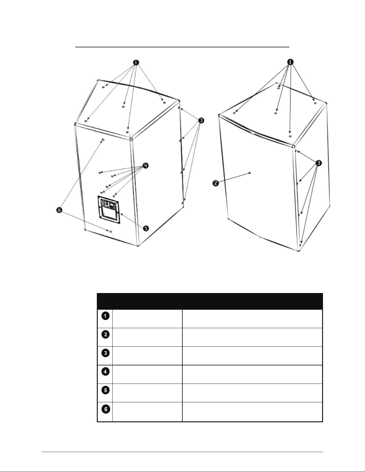
GETTING ACQUAINTED
Figure 1: Physical Features of a Typical VERIS Full-Range Model
PHYSICAL FEATURES OF VERIS FULL-RANGE MODELS
FEATURE DESCRIPTION
TOP & BOTTOM RIGGING
POINTS
PROTECTIVE GRILLE
GRILLE RETENTION
SCREWS
THREADED FITTINGS
FOR OMNIMOUNT™
INPUT PANEL
REAR PULL-BACK POINTS
Community VERIS Series - Operation and Installation Manual - Page 11
M6 or M10 threaded fittings, depending on model.
Powder-coated steel grille protects drivers from foreign
objects.
#6 x 5/8” sheet metal screws. Remove grille to
service drivers.
Fits OmniMount™ 30 or OmniMount 60™ series,
depending on model.
For amplifier connection to the loudspeaker. NL4 and
terminal strip are wired in parallel.
Used for angling enclosure downward; not intended
for primary rigging.
Page 12
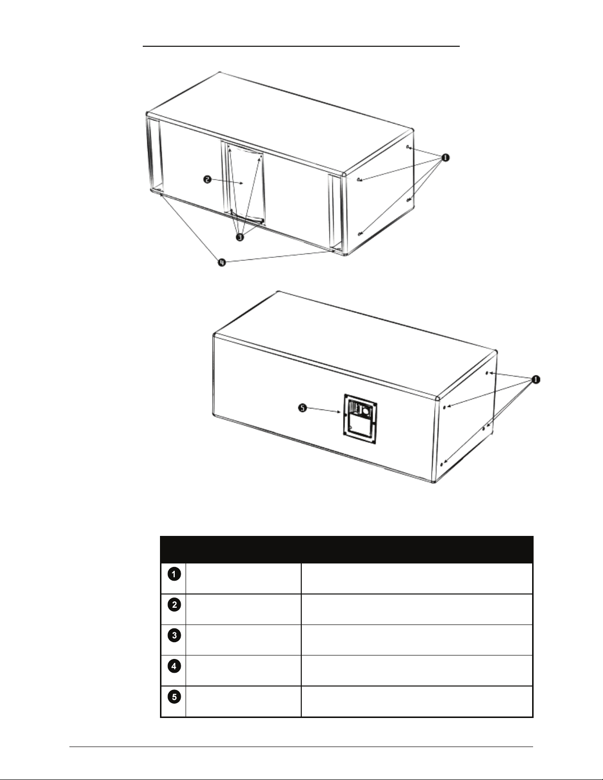
Figure 2: Physical Features of a Typical VERIS Subwoofer
PHYSICAL FEATURES OF VERIS SUBWOOFERS
FEATURE DESCRIPTION
RIGGING POINTS M10 threaded fittings. Four (4) on each side panel.
PROTECTIVE GRILLE
GRILLE RETENTION
SCREWS
FEET
INPUT PANEL
Community VERIS Series - Operation and Installation Manual - Page 12
Powder-coated steel grille protects drivers from foreign
objects.
#6 x 5/8” sheet metal screws. Remove grille to
service drivers.
Four synthetic rubber feet protect surfaces from
marring.
For amplifier connection to the loudspeaker. NL4 and
terminal strip are wired in parallel.
Page 13

GENERAL DESCRIPTION
VERIS Series loudspeakers are designed for demanding day-to-day use in a wide range of
fixed installations. Their high quality driver components are housed in rugged, acoustically
inert enclosures equipped with rigging fittings. VERIS systems are characterized by a highpower, low distortion linear response that provides exceptional musicality and speech
intelligibility.
The VERIS line consists of 10 models:
· VERIS6 - a 6” / ¾” two-way in a trapezoidal enclosure.
· VERIS8 - an 8” / ¾” two-way in a trapezoidal enclosure.
· VERIS26 - a dual 6” / ¾” two-way in a trapezoidal enclosure.
· VERIS28 – a dual 8” / ¾” two-way in a trapezoidal enclosure.
· VERIS12 – a 12” / 1” two-way in a trapezoidal enclosure with a choice of 60 x 40 or
90 x 60 horn patterns.
· VERIS15 – a 15” / 1” two-way in a trapezoidal enclosure with a choice of 60º x 40º
or 90º x 60º horn patterns.
· VERIS32 – a 12” / 6.5” / 1” three-way in a trapezoidal enclosure with a choice of
60º x 40º or 90º x 40º horn patterns. Horn is rotatable.
· VERIS35 - a 15” / 6.5” / 1” three-way in a trapezoidal enclosure with a choice of
60º x 40º or 90º x 40º horn patterns. Horn is rotatable.
· VERIS210S - a dual 10” subwoofer in a rectangular enclosure.
· VERIS212S - a dual 12” subwoofer in a rectangular enclosure.
Note: the specification table on pages 9 and 10 depicts dimensions, weights, and detailed
specifications of the ten VERIS models described above.
VERIS loudspeakers may be used in multiples, forming clusters and arrays. Systems may
be designed around horizontal splayed arrays, vertical splayed arrays, as well as exploded
clusters and distributed configurations. Rigging kits are available from the factory as
standard items.
DYNA-TECHTM DRIVER PROTECTION SYSTEM
All VERIS Series loudspeakers employ Community’s advanced technology DYNA-TECH
driver protection system. Functioning as a multi-stage limiter, DYNA-TECH circuitry
provides precise and repeatable protection by reducing excessive power to the drivers
under abusive conditions.
The first stage of limiting is designed to protect against short-term excess power applied to
the high-frequency driver(s) in the system. This circuit utilizes an HPCCR (High Positive
Current Coefficient Resistor) in series with the driver(s). The HPCCR increases resistance
as the current flowing through it increases. As its resistance rises above nominal, the
heating of the element provides RMS conversion. The result is an RMS limiter with a ratio
that varies according to the demands of the program material.
The second stage of limiting protects against excessive power levels to all drivers in the
system. This stage is based on an electro-mechanical relay driven through a voltage
sensing circuit. The relay engages at a pre-determined voltage, corresponding to a power
level that would otherwise cause driver damage. When engaged, the relay introduces a
bank of high-wattage resistors in series with the drivers. These resistors cause a voltage
drop to the drivers, thereby reducing the power applied to them. A red LED on the rear
panel indicates that this protection circuit has been engaged.
When the relay protection circuit is activated, there will be a noticeable drop in the system’s
level (approximately 3 to 4 dB). The red LED, as well as the drop in level, serves as a
warning to the operator that the loudspeaker is being overdriven. When this stage of
protection is engaged, the level of the console and/or the amplifier’s output to the
system should be reduced.
Community VERIS Series - Operation and Installation Manual - Page 13
Page 14

IMPORTANT: If the operator continues to run the system at excessive levels, or worse, if
the operator raises the drive level to compensate for the drop in output caused by the
protection circuitry, eventually an additional stage of protection will engage that shuts down
the system entirely (note that this additional stage of protection will never engage until
after the second stage has been triggered). If the system shuts down entirely, the operator
can immediately restore sound by simply reducing the drive level to the system.
Advantages of Community’s DYNA-TECH Circuitry
There are numerous advantages to this type of multi-stage protection circuitry. The trip
point is pre-set to engage at exactly the same time on all speakers that are powered from
the same amplifier. The initial stages of DYNA-TECH protection circuitry do not rely on, and
are not affected by heat build-up. Some manufacturers use circuit breakers that require
heat build-up before they trip; this limits their ability to protect a cold speaker. The trip
points of such breakers are also affected by ambient temperature, their own internal
heating curves, and small variations in speaker impedance or crossover component
tolerances, all of which can cause unpredictable behavior.
Because the first and second stages of Community’s DYNA-TECH circuits are not thermally
sensitive, they react nearly instantaneously to protect against an excessive increase in
level. Moreover, the protection disengages almost immediately when the drive level to the
system is reduced; it is not necessary to wait for a circuit breaker to cool down. This
means that your loudspeaker can operate at its full dynamic range and still react quickly to
protect against excessive musical peaks, avoiding damage to the system. It also means
that your loudspeaker is protected from the moment the power amplifier is plugged in and
turned on, regardless of the ambient temperature.
As mentioned above, the protection circuitry provides a third level of protection for the
entire loudspeaker to guard it from severe misuse. If the system is operated in the secondstage mode of protection for a long period of time, or if the input level is increased to try to
overcome the volume drop from the second-stage protection circuitry, a solid-state circuit
breaker will trip and remove all signal from the loudspeaker until the input level is reduced.
Because this circuit breaker is heat sensitive, it provides a final level of protection that
takes heat into account as well as power. However, unlike most implementations of circuit
breakers that take time to cool down before resetting, DYNA-TECH circuits respond
instantly to a reduction in level, restoring the system to its full dynamic range without
needing to wait for the circuit breaker to reset itself.
COOL-COIL™ TECHNOLOGY
The cone drivers used in the VERIS subwoofers utilize Community’s patented Cool-Coil™
heat evacuation technology. A proprietary process, Cool-Coil employs an airflow director to
remove heat from the voice coil, thereby increasing both the performance and reliability of
the cone drivers. In particular, the effect of Power Compression is significantly improved by
Cool-Coil technology. Power Compression occurs when drivers respond non-linearly to
applied power, producing less and less output as their voice coils heat up and their
impedance rises.
High voice coil temperatures have other undesirable effects on performance. Most materials
used in drivers, particularly adhesives and insulation, suffer some diminished properties
under extremes of heat. Thermal expansion can result in warpage and misalignment of
components. A voice coil in which the diameter has increased due to thermal expansion
will often no longer be round, and certainly has a greater possibility of rubbing against the
magnetic structure.
Any amount of cooling that can be applied to a woofer will be beneficial. One very
commonly used cooling method is venting of the pole piece of the magnet structure.
The motion of the cone assembly will pump air in and out of the cavity under the dust cap.
This air passing through the pole vent helps to cool the magnet structure. Community has
improved on this common cooling method by introducing an airflow director (US patent
6,390,231) into the air path. Figure 3 shows a conventional woofer motor with a vented
pole piece, and also a similar motor with the addition of an airflow director. The voice coil
former in the airflow motor is aluminum, and is taller than normal. This extended
aluminum former becomes a cooling fin for the voice coil, and the airflow director causes
the air to pass in close proximity to the former. By directing the air to flow over the hot
aluminum former, more heat is removed from the voice coil than simply allowing the
Community VERIS Series - Operation and Installation Manual - Page 14
Page 15
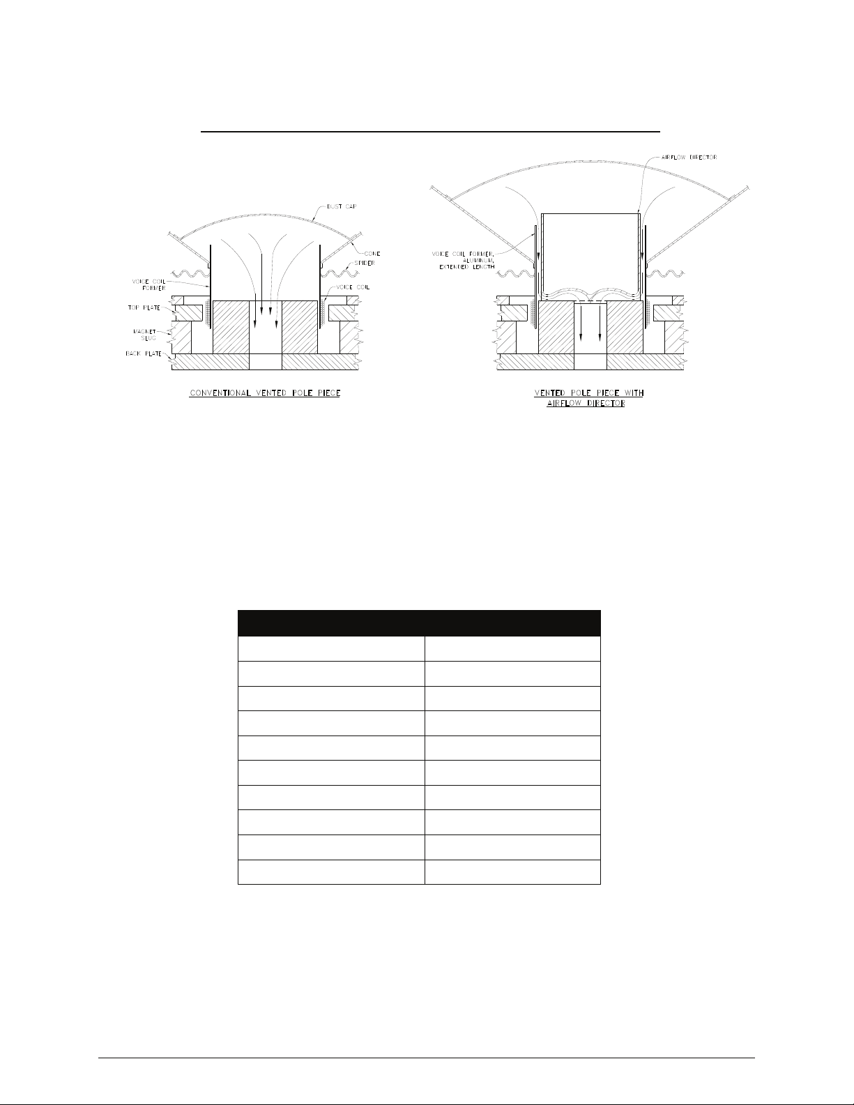
pumped air to take its natural path in and out of the cavity. This results in woofers that can
handle higher power with greater reliability than those of conventional design.
Figure 3: Community’s Cool-Coil™ Heat Evacuation System
HIGH-PASS FILTERS
We strongly encourage the use of an external, active high-pass filter to protect the cone
drivers from excessive low-frequency excursion. A high-pass filter will eliminate the
potential of low-frequency modulation from wind noise, turntable rumble, stage vibration,
and other causes that result in a poorly defined and ‘muddy’ bass response. Additionally, a
high-pass filter will avoid wasting amplifier power by keeping the amplifier from attempting
to reproduce frequencies below the loudspeaker’s intended operating range. The table
below shows the recommended filter settings:
Model High-Pass Filter
VERIS6 Full-Range: 100 Hz, 24db/octave
VERIS8 Full-Range: 90 Hz, 24db/octave
VERIS26 Full-Range: 80 Hz, 24db/octave
VERIS28 Full-Range: 70 Hz, 24dB/octave
VERIS12 Full-Range: 60 Hz, 24db/octave
VERIS15 Full-Range: 60 Hz, 24db/octave
VERIS32 Full-Range: 60 Hz, 24db/octave
VERIS35 Full-Range: 60 Hz, 24db/octave
VERIS210S Subwoofer: 40 Hz, 24db/octave
VERIS212S Subwoofer: 40 Hz, 24db/octave
Community VERIS Series - Operation and Installation Manual - Page 15
Page 16
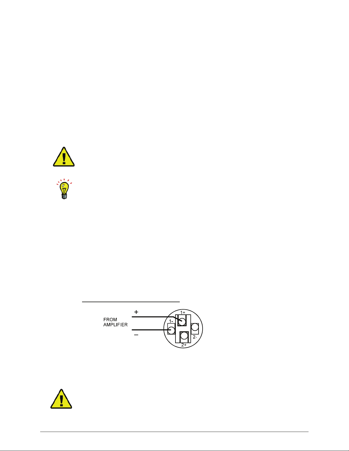
CONNECTING THE AMPLIFIER TO THE LOUDSPEAKER
All VERIS Series loudspeakers come with two methods of connecting the amplifier to the
loudspeaker. One is an industry standard NL4 type locking connector, and the other is a
terminal strip. These two connectors are wired in parallel with each other, on all models.
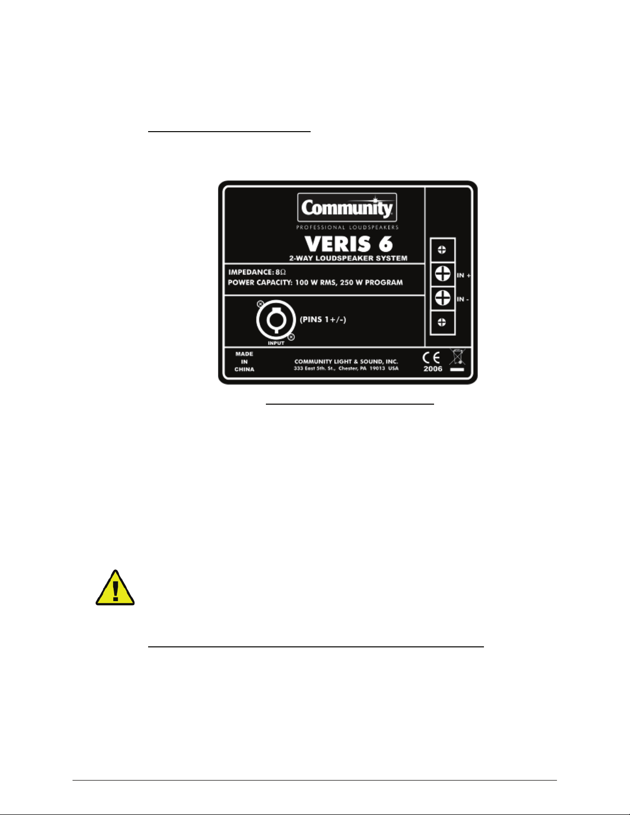
Figure 4: VERIS Input Panel
The following figure is an example of a typical input panel used on VERIS loudspeakers.
A similar panel is used on all standard, low impedance VERIS models. The loudspeaker is
intended to be connected directly to the amplifier.
Typical Standard Input Panel
PIN DESIGNATIONS
For all models the pin designation is as follows:
• NL4 Pin 1+ or the terminal screw labeled (+) connect to the positive (red)
output of the amplifier.
• NL4 Pin 1- or the terminal screw labeled (-) connect to the negative (black)
output of the amplifier.
Note that the NL-4 and the terminal strip are wired in parallel, and that Pins 2+ and 2- on
the NL4 connector are not utilized.
CAUTION: Be sure to carefully observe polarity when wiring your loudspeakers. If one
loudspeaker is wired with the opposite polarity from another loudspeaker, acoustic
cancellation will occur. The result will be less acoustic power output than if only one
loudspeaker were used by itself.
Figure 5: VERIS Input Panel, Optional Autoformer Version
The following figure is an example of the input panel used on VERIS loudspeakers equipped
with an optional autoformer. Such models are intended to be used in a 70V or 100V
“constant voltage distribution system.”
Community VERIS Series - Operation and Installation Manual - Page 16
Page 17
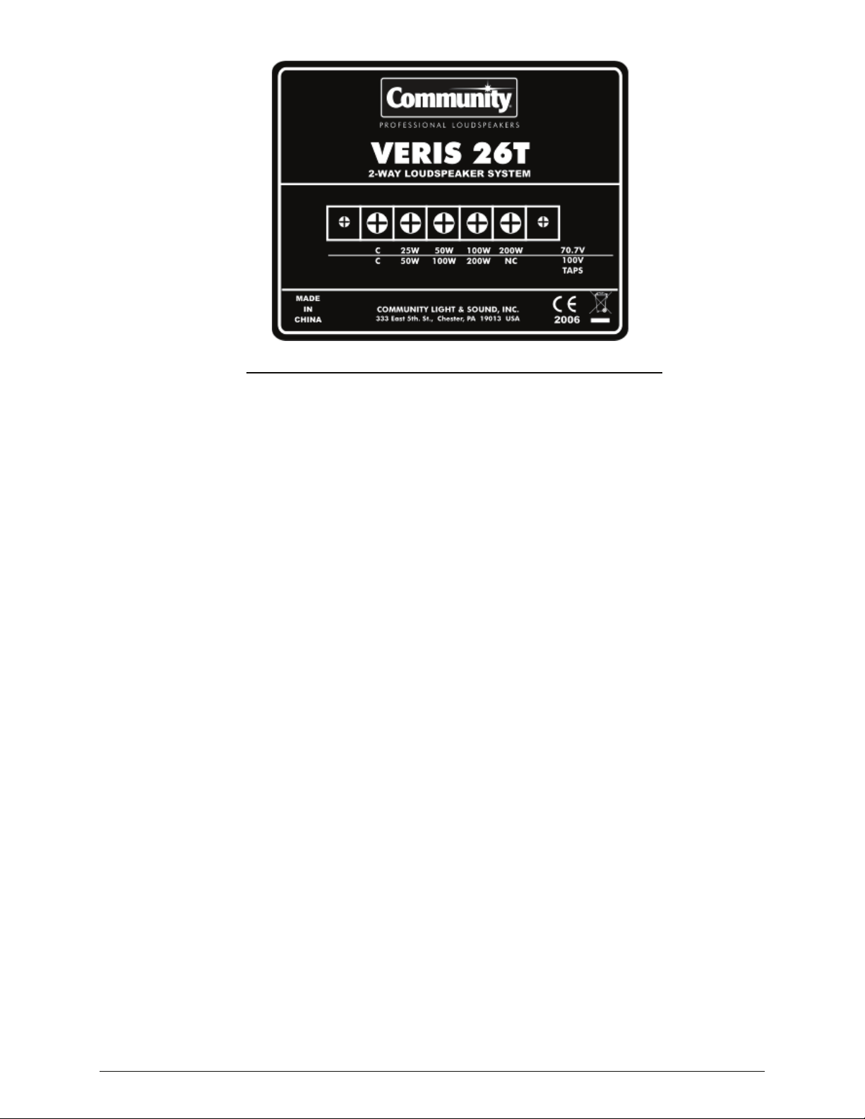
Typical Input Panel for Autoformer Equipped Models
PIN DESIGNATIONS
The pin designation is as follows:
• ‘C’ or ‘common’ connects to the ‘C’ or Ground connection on the amplifier
(typically a black binding post).
• One of the taps connects to the positive output of the amplifier (typically a red
binding post).
USING POWER TAPS
A VERIS loudspeaker equipped with an optional autoformer has four taps. These are set at
25W, 50W, 100W and 200W on the two larger models, and 12.5W, 25W, 50W and 100W on
the two smaller models.
By choosing one of the four taps, you can govern how much amplifier power is available for
each loudspeaker. For example, if the 50W tap is selected, that particular loudspeaker will
draw 50 watts of power when a 70V amplifier is run at its maximum level. A second
loudspeaker might be connected to the same amplifier, but tapped at 100W (100 watts). In
such case, the second loudspeaker will draw 100 watts from the same amplifier, making it 3
dB louder than the first loudspeaker. A third loudspeaker might be tapped at 200 watts,
which would make it 3 dB louder than the second loudspeaker, and 6 dB louder than the
first.
By using the various taps, one can balance the relative sound levels in a system. A
loudspeaker that is closer to audience members will need to be tapped at a lower wattage
than one that is farther away, in order to produce similar levels.
Typically, every time you double the distance from a sound source, the level drops by 6 dB,
which is equivalent to one-fourth of the power. Although this is an acoustical law, and is
true in a free space environment such as outdoors, be aware that the effect of room
acoustics can radically change the actual results. Even outdoors, it is normally not possible
to validate this acoustical law using a sound level meter, due to the ground plane effect.
That said, the use of pink or white noise to excite the system, and a sound level meter to
take nearfield measurements, will help you precisely balance the relative level of each
loudspeaker in a sound system. Just make sure to take your readings at an identical
distance from each of the loudspeakers in the system, otherwise the results will be skewed.
Community VERIS Series - Operation and Installation Manual - Page 17
Page 18
70.7V and 100V SYSTEMS
Several voltage standards have been put in place regarding so called ‘constant voltage
systems.’ In the United States, 25V, 70.7V and 100V are common. Occasionally 140V
systems can be found, usually in very large venues such as racetracks, where the need to
overcome cable resistance by scaling the voltage up is extremely important. In Europe and
Asia, most constant voltage systems use the 100V standard.
A VERIS loudspeaker equipped with the optional autoformer will support both the 70.7V and
100V standards. The same screw terminals are used for both voltage standards, but the
power level of the tap is different, depending on whether the voltage is 70.7V or 100V.
Note that on the rear input panel, the power levels above the horizontal line refer to a
70.7V system, while the power levels below the line refer to a 100V system.
A 100V system will produce twice the power at a given tap, as that of a system run at 70.7
volts. This can be verified by the simple Ohm’s Law calculation E
2
/Z = W, where E is the
voltage applied, Z is the load impedance, and W is the power expressed in Watts.
Assuming a load impedance of 50 ohms, we can see that 70.7 x 70.7 / 50 = 99.97 and that
100 x 100 / 50 = 200. Therefore, when scaling up from 70.7V to 100V the power will
double; when scaling down, the power will halve.
CAUTION: Be sure to carefully observe polarity when wiring your loudspeakers. If one
loudspeaker is wired with the opposite polarity from another loudspeaker, acoustic
cancellation will occur. The result will be less power output than if only one loudspeaker
were used by itself.
C-TIP: When using the barrier strip for wiring, we recommend that you first terminate the
wire with a plated copper crimp-on type spade lug, using moderate to heavy pressure on
the crimp tool. When the spade lug is tightened firmly on the barrier strip, it will form a
gas-tight connection resistant to corrosion. Be careful not to over-tighten the barrier strip
screws, as they can sheer off under too much torque. This is the recommended method of
wiring for fixed installations, especially those that may be exposed to inclement
environmental conditions.
WIRING NEUTRIK TYPE CONNECTORS
The following diagram shows how connections are made to a Neutrik SpeakonTM style
loudspeaker connector. Terminations may be soldered, or made by means of their built-in
screw and pressure clamp. If using the pressure clamp, it’s important to tighten it fully,
then to wait about ten minutes (longer is better), then to tighten it again. This is because
copper wire flows under pressure. After initially tightening the screw clamp, some minutes
later the screw will no longer be as tight due to the effect of the compression on the
copper. Typically, only one cycle of “tighten – wait – re-tighten” is required for a secure
connection.
Figure 6: NL4-Type Connector
NEUTRIK SPEAKON™
CONNECTOR – NL4FC
Note: Pins 2+ and 2- are not used in the VERIS loudspeaker series.
DANGER: When wiring the amplifier(s) to the loudspeaker(s), always power-down the
amplifier(s) and disconnect their AC Mains plug(s). Many modern, high power amplifiers
can deliver enough voltage and current to cause a harmful or lethal electric shock. Shocks
from very low frequencies, such as kick drums, can cause the human heart to stop beating
at relatively low power levels.
Community VERIS Series - Operation and Installation Manual - Page 18
Page 19
WARNING: After wiring the amplifier(s) to the loudspeaker(s), first power up all devices
that are upstream of the amplifier, such as mixers, equalizers, compressor/limiters, etc.,
before powering-up the amplifier. This is to avoid passing any clicks or pops that may
originate in the upstream devices to the loudspeakers. The amplifier should initially be
powered-up with its gain controls turned all the way down. After making sure that a
continuous signal is present, such as a CD playing, slowly raise the level of the gain
controls to establish that the wiring has been installed correctly. Only then should the
loudspeaker be operated at normal output levels.
KNOW YOUR AMPLIFIER
Not all amplifiers can safely drive low-impedance loads, though usually 4 ohms and higher
is not a problem. Very low impedance loads may cause the amplifier to clip prematurely,
overheat, shutdown, or fail altogether due to internal device damage.
Even when an amplifier is quite stable driving a low impedance load, cable loss will be
greater than with moderate impedance loads, damping factor will be reduced, and if the
amplifier were to fail, a larger portion of the sound system is likely to be taken off-line due
to the fact that a low impedance load implies a larger number of loudspeakers being
powered from a common amplifier.
C-TIP: Keeping the loads at 4 ohms or higher will lengthen the life of your amplifier(s) and
improve the reliability and overall sound quality of the system.
CHOOSING LOUDSPEAKER WIRE
Wire and cable is used to transfer power between the amplifier and the loudspeaker. Wire
and cable can be purchased with copper and aluminum conductors; for loudspeakers only
copper conductors should be utilized.
The construction, conductor type, and insulation material of wire and cable vary widely.
Wire can be purchased with solid core construction, stranded core construction, and densely
stranded construction. Cables are typically available only as stranded or densely stranded.
Speakers may be driven through individual conductors bundled together and pulled through
conduit, or through a cable made up of a number of conductors covered with an overall
jacket, which then may or may not necessarily be installed in a conduit. Wire and cable
manufacturers offer multi-conductor cables with 30 or more high current conductors
covered with a variety of jacket types. Jackets may be made of PVC, rubber, neoprene,
and other materials, depending on the intended conditions of use.
Generally speaking, the wires and cables that power loudspeakers do not need to be
twisted into pairs, though there is some benefit to doing so. A twisted pair of conductors
has the effect of cancelling electro-magnetic radiation, thereby reducing mutual induction
among circuits that share the same physical space (such as a cable tray or conduit), along
with canceling the crosstalk that might otherwise result.
Twisted pairs are commonly used for balanced line signal and microphone cables, in which
the nominal voltages are very low and the input impedance of the load is typically quite
high (>10K ohms). Under such conditions, the use of a twisted pair is essential to reduce
crosstalk among adjacent cables. The twisting insures that the differential amplifier in a
balanced line receiver will see identical phase and amplitude of any extraneous Electro
Magnetic Interference (EMI) induced in the cable on both polarities, thereby allowing the
EMI to be differentially cancelled.
In contrast, however, loudspeakers have input impedances that are quite low and operate
on much higher voltages. The potential of inducing an audible signal from adjacent wiring
is close to zero. The installer may, however, choose to use twisted pair loudspeaker cable
for other reasons. Certain amplifiers may exhibit instability when driving long lengths of
wire installed in conduit. A twisted pair will insure that the reactance of the loudspeaker
cable is identical on both the plus and minus wires, thereby presenting a more stable load
to the amplifier.
Note that when specifying multiple twisted pairs of speaker cables intended to share the
same conduit, the conduit will need to be sized much larger than with loose or bundled
conductors.
Community VERIS Series - Operation and Installation Manual - Page 19
Page 20

CONDUCTORS AND INSULATION
Solid conductor wire is slightly less expensive than stranded wire, but much more difficult
to pull through conduit. Also, it does not terminate to most speaker connectors as easily as
stranded wire. Therefore, we recommend using stranded THHN type wire for installations
that involve conduit.
Densely stranded cables, typically used for portable cordage, will coil up easily and lay flat
on the stage, making them a good choice for applications requiring portability such as floor
monitors. Typical examples are 14/2 and 14/4 SJO. Such cable is normally stocked in
many hardware stores.
Wire and cable insulation is always rated for a working voltage and a maximum
temperature. In power distribution systems, wire and cables can get very hot, making the
temperature rating extremely important. When used with loudspeakers, the temperature of
the wire or cable will hardly ever rise more than 10º C above ambient, and voltages will
never exceed 300V (which is the minimum rating of most industrial wire and cable).
Special cables are manufactured for installation in air plenums, while others are made for
direct burial. Use of such products can save a lot of time and expense compared to
installing conduit. However, local, state, or federal building codes may require that
loudspeaker cables are installed in conduits or in cable trays. Therefore, it’s a good idea to
check applicable regulations carefully, before beginning any installation.
In the United States, conductors are sized according to a numbering system know as the
American Wire Gauge, or AWG. Larger numbers, such as #22 or #24 indicate smaller
diameter wire, while smaller numbers such as #10 and #12 indicate larger diameter wire.
In other parts of the world, the metric system is widely used to define conductor diameter.
Metric equivalents can be converted to US AWG sizes, with only a small loss of precision.
The larger the diameter of the conductor, the lower the resistance will be for a given length.
Resistance is normally stated per foot, or per hundred feet of wire. For example, #10
stranded copper THHN has a resistance of .204 ohms per hundred feet, though this can
vary slightly among manufacturers.
The resistance of the wire, the impedance of the load, and the output voltage of the
amplifier will determine how much loss occurs in the wire. These parameters also govern
the damping factor of the amplifier/speaker combination (more on this later).
Below is a table that gives a quick look at the effect of wire size on line loss. These
numbers assume that the amplifier is producing a constant 48 Volts at its output terminals,
which is equivalent to 288 watts into an 8Ω load or 576 watts into a 4Ω load:
Size Length Load Z Loss in dB
#10 AWG 100’ 8Ω -0.42 dB
#10 AWG 200’ 8Ω -0.83 dB
#10 AWG 100’ 4Ω -0.83 dB
#10 AWG 200’ 4Ω -1.58 dB
#12 AWG 100’ 8Ω -0.66 dB
#12 AWG 200’ 8Ω -1.28 dB
#12 AWG 100’ 4Ω -1.28 dB
#12 AWG 200’ 4Ω -2.39 dB
#14 AWG 100’ 8Ω -1.03 dB
#14 AWG 200’ 8Ω -1.95 dB
#14 AWG 100’ 4Ω -1.95 dB
#14 AWG 200’ 4Ω -3.55 dB
The worst-case scenario shown above is the 200’ run of #14 AWG into a 4 ohm load. This
will result in a staggering loss of -3.55 dB, or more than half of the amplifier’s total power
output. Use of wire that’s one size smaller, #16 AWG, would cause a power loss of -5.11
dB. This approaches a 75% loss of total available power! As you can readily see, it’s very
important to use the largest gauge wire that you possibly can, particularly when long lines
are unavoidable. Note: NL4-compatible connectors easily accept #12 AWG.
Community VERIS Series - Operation and Installation Manual - Page 20
Page 21

C-TIP: When choosing cable for a situation that requires only two conductors, consider
using 14/4 (that is, #14 AWG with 4 conductors) and wiring each pair of conductors in
parallel, at both ends of the cable. This will provide the equivalent conductance of #11
AWG, but in a cable that’s more easily obtainable and smaller in diameter.
THE EFFECT OF WIRE GAUGE ON DAMPING FACTOR
As significant as power loss can be, the effect of wire resistance on the damping factor of
the loudspeaker/amplifier network is even greater for a given resistance value.
Amplifier designers intend for the output impedance of their amplifiers to be as low as
possible, in order to achieve a high damping factor. However, the laws of physics dictate
that a very low output impedance will cause the resistance of the speaker cable to have a
significant effect on the amplifier/speaker network. Unfortunately there’s no way to get
around it.
Example: With five feet of #10 AWG feeding a 4 ohm load, a given amplifier exhibits a
respectable 100:1 damping factor. With fifty feet of #10 AWG feeding the same 4 ohm
load, the damping factor decreases to 10:1, which is likely to be audible as a loss of ‘punch’
and tightness in the low frequencies.
Unless the power amplifiers are located directly alongside the loudspeakers (a good design
technique to consider when possible), it will be difficult to maintain a high damping factor
without using impractically large conductors. Therefore, keeping cable lengths as short as
possible, is the most practical and cost-effective way to maintain a respectable damping
factor without incurring undue difficulties.
C-TIP: Although it’s beyond the scope of this manual to test and rate the many specialty
loudspeaker cables sold in audio shops, studies conducted by skilled engineers have
conclusively shown that the majority of such cables offer no real performance advantages
(and in some cases, notable disadvantages) over that of readily available industrial grade
wire.
SELECTING AMPLIFIERS
Amplifiers are a vital part of any sound system’s performance capability. As such, they
should be carefully selected for appropriate power output, as well as for other attributes
(more on this later). A table is provided below to help you size your amplifiers’ power
output capability to the various models in the VERIS line.
Model Recommended Power
VERIS6 Full-range 200 to 300 WRMS at 8Ω
VERIS8 Full-range 310 to 450 WRMS at 8Ω
VERIS26 Full-range 420 to 600 WRMS at 4Ω
VERIS28 Full-range 630 to 900 WRMS at 4Ω
VERIS12 Full-range 420 to 600 WRMS at 8Ω
VERIS15 Full-range 420 to 600 WRMS at 8Ω
VERIS32 Full-range 420 to 600 WRMS at 8Ω
VERIS35 Full-range 420 to 600 WRMS at 8Ω
VERIS210S Subwoofer 630 to 900 WRMS at 4Ω
VERIS212S Subwoofer 600 to 900 WRMS at 4Ω
Note: “WRMS” = “Watts RMS” = “Watts Root Mean Squared”
Community VERIS Series - Operation and Installation Manual - Page 21
Page 22

VERIS APPLICATIONS
In choosing the right VERIS product for your application, the initial factors to consider are
the size of the venue, the style of music and speech to be reproduced, and the location(s)
of the loudspeaker(s).
In smaller venues with less demanding musical styles, one can usually achieve excellent
results with the VERIS12 and the VERIS15 models. A good rule of thumb is to use a pair of
these models for venues that host up to approximately 200 persons.
By adding a second pair of either the VERIS12 or VERIS15, venues that host as many as
300 to 400 persons can be effectively covered. Each pair of enclosures may be configured
side-by-side or one over another, to produce additional forward radiated power.
In rooms that are particularly wide but shallow in depth, a second pair may be required
simply to obtain the necessary horizontal coverage, even if overall power is not an issue.
The VERIS15, with its 15” cone driver, will provide additional low-frequency content than
that of the VERIS12, which has a 12” cone driver, resulting in a richer, fuller response.
However, if either model is to be used with the VERIS210S or VERIS212S subwoofers, the
difference in the response between the VERIS12 and the VERIS15 will be minimal.
VERIS32 and VERIS35 models are true three-way designs, employing horn loaded midrange drivers in addition to their horn loaded high-frequency drivers. This design yields
better directional control than a two-way system. The added directionality is an asset in
reverberant rooms where it’s important to keep the sound energy off of the walls, floor and
ceiling, and/or when there’s a need to cover long distances, either indoors or out.
The larger VERIS35 with its 15” cone driver will provide deeper low-frequency response
than that of the VERIS32 which employs a 12” cone driver, but here again the difference in
response will be minimal if either model is used with a VERIS subwoofer.
The small VERIS6 and VERIS8 loudspeakers are ideal for small rooms (25 – 75 persons), as
well as for distributed systems in large rooms. They can also be used as ‘delay speakers,’
augmenting a larger system to balance out the levels from the front of the room to the rear
of the room. The practice of driving small speakers through a delay line is used in many
theatrical systems, concert hall systems, and houses of worship. It gives the installer a
powerful tool when it comes time to equalize and balance the system.
In large rooms, and especially those in which the acoustical conditions are not ideal, we
strongly recommend the use of under-balcony delay speakers, over-balcony delay
speakers, front fill speakers, etc. In areas of the room that are too far away from the
primary loudspeaker(s) to enjoy clear intelligibility, the addition of local, delay speakers can
do wonders in solving problems.
The VERIS26 and VERIS28 models provide twice the woofer cone area of their smaller
cousins. The second woofer cone provides more overall power with greater bass response.
These models are a good choice for distributed music systems, such as in health clubs,
bars, restaurants and the like.
The VERIS line includes two subwoofers; the 210S employs dual 10” drivers, while the
212S features dual 12” drivers. Either model will add greatly increased power and
extended low-frequency response to the VERIS full-range loudspeaker(s) that it’s used
with.
The smaller of the two, the 210S, is characterized by a tight, punchy sound, while the
larger 212S adds a deeper low end, but still with a very rapid transient response. When
using multiple subwoofers, such as two or three on each side of a stage, it’s best to keep
the enclosures stacked or positioned tightly together for maximum mutual coupling.
If an external electronic crossover is employed, the use of a subwoofer will free up the lowfrequency power demand on the full-range loudspeaker(s), thereby increasing output
capability in the upper bass range. An electronic crossover will also reduce intermodulation
distortion in the amplifiers, resulting in much improved sonic performance.
Note: The guidelines referred to above are “rules of thumb only.” Performance
will vary based on room acoustics, room geometry (particularly ceiling height),
the location of the loudspeaker(s), the size and type of the amplifiers, and the
stylistic demands of the music and speech that are to be reproduced.
Community VERIS Series - Operation and Installation Manual - Page 22
Page 23

POSITIONING SUBWOOFERS
Subwoofers are far less directional than the mid-range and high-frequency loudspeakers
they are designed to augment. This is because low-frequency wavelengths are significantly
longer than mid-range and high-frequency wavelengths. A 30 Hz wave is approximately 35
feet in length and a 100 Hz wave is approximately 11.3 feet in length. These extremely
long wavelengths cause behavior that’s quite different from their shorter mid and highfrequency counterparts.
First, long wavelengths do not ‘see’ small or moderate size obstructions as obstacles; they
simply diffract around such barriers as if they’re not there.
Second, the substantial length of low-frequency waves can make it difficult to distinguish
their source direction. This is why a single subwoofer can often be used successfully to
augment a stereo pair of mid-high loudspeakers, without unduly harming the stereo
separation and image.
Third, low-frequency waves tend to add together quite graciously, even if their sources are
separated by considerable distances, as long as they are in phase with each other. An
example of this in operation is the typical accentuation or build-up of low-frequency content
that is often experienced in the middle of theatres and concert halls, generated by
subwoofers placed far apart on the opposite sides of the stage.
Overall, the characteristics mentioned above imply that the location of a subwoofer is not
particularly critical, and to a certain extent that is true. However, there are several factors
to consider before you finalize your intended location
(1) A subwoofer will benefit greatly in terms of power output when it’s placed adjacent to
boundary surfaces. If located at the junction of three walls, such as on the floor or
ceiling in a corner (called Eighth Space), a given subwoofer will produce a full 9dB more
output than if that same subwoofer is located in Free Space (such as when suspended
between the middle of a floor and ceiling). If located at the junction of two walls
(Quarter Space), the subwoofer will produce 6dB more output than if suspended in Free
Space. Located on a single wall, such as the floor or ceiling, the increase is 3dB. Free
Power! What could be better? See Figure 8 for additional clarification:
Figure 8: Effect of Boundary Surfaces on Power Output
1
. Some of these are:
1
A thorough understanding of how low-frequency waves transmit in acoustical environments is very helpful when designing,
installing, and optimizing sound systems. We recommend reading, “Fundamentals of Sound” and “Psychoacoustics” by F. Alton
Everest in the “Handbook for Sound Engineers” published by Howard Sams & Co.
Community VERIS Series - Operation and Installation Manual - Page 23
Page 24

When choosing subwoofer location(s), be careful, however, not to sacrifice sonic quality
for sheer power. If the available wall or corner location results in the subwoofer being
located behind, or too close, to one or more open microphones, early feedback is likely
to occur. If the wall or corner location is too far away from the full-range
loudspeaker(s), such a location may result in the subwoofer being drastically out of
time sync with one or more of the full-range speakers.
Sometimes the sound quality of a wall or corner placement is not desirable, simply due
to the room’s acoustical properties. Keep in mind that when wall and corner locations
are appropriate for use, they’ll provide a tremendous increase in power output, but
they may not always be the best choice for sound quality.
(2) Keeping the subwoofer(s) as close as possible to the mid and high loudspeaker(s) will
decrease phase irregularities and time smear. If the subwoofer(s) is placed too far
away from the mid/high loudspeaker(s), the listener will experience a disjointed
character to the program material, causing the musicality of the system to suffer.
(3) Although the subwoofer is not highly directional, still its acoustical output follows the
inverse square law. That is, every time the distance from the subwoofer to the listener
is doubled, the output level will decrease by 6dB. When covering a large space with
multiple subwoofers, it may be of benefit to space them some distance apart from one
another to even out the levels throughout the space. Typically, this would only be done
if the mid/high loudspeakers are also spaced apart from one another, such as in a
distributed system in a sports venue. Although this will help maintain an even level
throughout the listening space, there may be some areas that lie between two or more
subwoofers that experience a certain amount of power subtraction caused by
destructive interference. Destructive interference occurs when waveforms meet and
are partially or wholly out of phase with each other, due to unequal path lengths.
Conversely, if multiple subwoofers are located directly adjacent to one another, their
power output will add together almost seamlessly. This is known as constructive
acoustic addition. However, this may produce an undesirable hot-spot of low-frequency
energy that might possibly be too close to a seating area.
It’s always a good idea to experiment with trial locations, before finalizing your
installation plan. Even a very experienced sound system designer cannot predict the
precise effect that one location may have over that of another, if he/she is not
intimately familiar with the room acoustics. When planning loudspeaker locations, it’s
wise to discuss the matter with someone who may have prior experience operating
sound systems in that particular room, such as the resident mixing engineer, if the
building has previously had a sound system installed in it.
POLARITY
Unless the full-range loudspeaker(s) is stacked directly on top of the subwoofer(s) with its
cone drivers aligned with the subwoofer cone drivers, it’s likely that the phase relationship
of the two systems may not be optimal. This can be tested by reversing the polarity of one
system relative to the other, as described below.
First, however, it’s important to understand that the correct polarity of the full-range
system relative to the subwoofer is a function of their physical placement in relation to one
another. This is known as the Phase Relationship of the two systems, though Absolute
Polarity plays a role as well, which will be discussed later.
Depending on the placement of the subwoofer in relation to the full-range loudspeaker(s),
as well as the selected crossover point, the optimal response of the system might be
obtained by reversing the polarity of the full-range loudspeaker(s). The easiest way to
determine the proper polarity is to excite the system with a test signal (such as pink noise)
and to view the resultant response on an audio spectrum analyzer. If such equipment is
not available, it is also possible to determine the best polarity relationship by careful
listening.
One orientation of polarity, either normal or reversed, should result in a discernable dip
through the crossover region, due to acoustic cancellation. The opposite polarity should
result in either a flat response or a peak through the crossover region, due to acoustic
addition.
Note: When experimenting to determine the proper polarity, you can reverse the full-range
loudspeaker(s) or the subwoofer, but never both at the same time (reversing both at the
same time will not alter the phase relationship of the two systems). If there is one
Community VERIS Series - Operation and Installation Manual - Page 24
Page 25

subwoofer and several full-range enclosures in the same system, it will, of course, be easier
to reverse the subwoofer’s polarity to test the response. Ultimately, as we’ll see below, it’s
best to keep the subwoofer in a polarity-positive state.
If there is no discernable difference or only a very minimal difference in the measured or
audible response when the polarity is reversed, it indicates one of two things:
(1) The full-range system that the subwoofer is being used with does not reproduce
enough low-frequency output to cause either cancellation or addition with the
subwoofer. This would be true if the full-range system is a very small loudspeaker, like
those that are used for front-fill and underbalcony fill.
(2) The placement of the subwoofer in relation to the full-range loudspeaker is not
optimum. Little or no response variation will occur if the physical relationship results in
an approximate ¼ wavelength of offset at the center of the crossover frequency.
The solution to (1) is for both systems to remain in positive polarity. No harm will occur if
the full-range system simply does not reproduce enough low-frequency energy to either
add or cancel with the subwoofer’s output.
The solution to (2) is to either change the physical relationship of the two systems, or to
delay one of the two systems (whichever one is positioned closer to the listeners) with a
digital delay. A high-quality, high resolution measurement system that can read and depict
phase response or impulse response would be very useful in this situation. However,
without such a system, you can determine an effective delay time by trial and error.
Simply increment the delay time in small steps (1 ms), until the action of reversing the
polarity produces maximum cancellation in one orientation and maximum addition in the
opposite. By using a digital delay, you will have preserved the phase and impulse response
of the system and you can now filter out any objectionable mid-bass overlap with an
equalizer.
If a delay is not available, it is recommended that either the subwoofer or the full-range
loudspeaker be relocated closer together, so that reversing the polarity of either the
subwoofer or the full-range loudspeaker (but not both at once) will result in a distinct dip at
crossover as discussed above.
If this cannot be done due to physical restrictions, the subwoofer and the full-range
loudspeaker should be moved further apart, again until there is a distinct dip at the
crossover frequency in one position of polarity. It may take some trial and error to
determine the optimal physical relationships.
C-TIP: It’s a good idea to experiment with different loudspeaker locations by conducting
listening tests before you finalize the locations (especially important in permanent
installations). Make sure to use live microphones and live instruments (if applicable), as
well as track playback. Choosing the physical location of the loudspeakers in the room is
always the most important part of any successful system installation.
Note that in some acoustical environments, the system may sound better when the phase
relationship is non-optimum resulting in a dip at crossover, compared to optimum phase
where the crossover region is accentuated by the overlap of the subwoofer and the fullrange speaker(s). However, this is not the best way to achieve the sound that you’re
seeking. The proper course of action is to equalize (EQ) the peak at crossover with a
parametric equalizer until the response is flat, or until you’ve achieved the tonal response
you desire (we’ll explain why below).
Alternatively, you might insert a high-pass filter in the full-range system (typically at 80 –
100 Hz with a 12dB/octave slope), so that the overlap with the subwoofer is reduced in
magnitude.
A third technique is to increase the slope of the crossover to 24 dB per octave or 48 dB per
octave, if the crossover has such capability, thereby reducing the bandwidth of the
spectrum in which the two sources overlap.
There’s an important reason for taking one or more of the measures discussed above. If
that nice-sounding response dip at crossover is in fact due to phase cancellation, it means
that the drivers and amplifiers will be working harder than they should to produce less
sound pressure level than they are capable of, due to the acoustic cancellation taking place.
All that cancelled energy uses power unnecessarily!
Community VERIS Series - Operation and Installation Manual - Page 25
Page 26

Instead of putting the two systems out-of-phase to get the sound you want, if you
attenuate the peak at crossover with any of the methods described above
reducing the power that’s required to obtain a given sound pressure level. This will result
in more available power, more headroom and less demand on the drivers, all of which
lowers the potential for distortion and damage under high power conditions.
Now that you’ve chosen the final physical locations for your full-range loudspeakers and
subwoofers, established their optimum phase relationship, and brilliantly EQ’d any
crossover peaks, you’re almost ready to permanently wire the system. But first read the
section below on “Choosing the Right Loudspeakers and Electronics.”
2
, you are
CHOOSING THE RIGHT LOUDSPEAKERS AND
ELECTRONICS
Choose VERIS models with high enough maximum SPL to provide the needed SPL at the
farthest listener with an appropriate headroom. Typical headroom factors are at least 6 dB
for voice paging, at least 10 dB for voice reinforcement and at least 20 dB for music
reinforcement.
Choose VERIS models with the right frequency response for the application. Subwoofers
will improve the sound quality of a music reinforcement system but may reduce
intelligibility in a voice-only system in a reverberant space.
Choose VERIS models with the right coverage patterns to cover the audience evenly. Point
the loudspeakers at the listeners and away from walls and ceilings or other obstructions.
Ideally, put all loudspeakers in a central location (central cluster design) or use a
distributed system design. Minimize overlap when loudspeakers are separated by more
than approximately 40 feet.
Choose power amplifiers large enough to achieve the needed SPL in the venue with enough
headroom to avoid clipping. Use a limiter and high-pass filter to protect the loudspeakers.
Follow proper wiring design and adjust gains and levels to achieve the best signal to noise
ratio.
COMMISSIONING THE SYSTEM
Commissioning is the process of optimizing the performance of the system after it has been
installed. There are several steps in commissioning including verifying the proper operation
of each system component and adjusting system gains and levels.
The last step in system commissioning is known as system equalization or “voicing.”
Equalization is the process of adjusting the frequency response of the system to optimize
voice intelligibility or musical sound quality (or both). Note that VERIS loudspeakers are
factory voiced to optimize their speech intelligibility and musical sound quality. For this
reason, many designers find they can minimize overall system equalization and still achieve
excellent voice intelligibility and musical sound quality.
When equalizing a VERIS loudspeaker system the following points should be kept in mind to
achieve the best results and to avoid damaging the drivers.
1. Use only small amounts of equalization. In particular, do not boost frequencies by more
than about 3 dB. When cutting frequencies more than 3 dB of attenuation is acceptable.
Bear in mind that extreme frequency cuts will usually result in less than optimum
performance.
2. Do not attempt to boost any frequencies below 100 Hz with a graphic equalizer. Note
that with the recommended high-pass filter, moderate amounts of boost from a simple bass
control are acceptable.
2
The three corrective methods referred to in the text, equalizing, high-passing, and increasing the slope of the crossover, are all
various implementations of equalization.
Community VERIS Series - Operation and Installation Manual - Page 26
Page 27

For More Information And Applications Assistance
For more information on installing and operating your VERIS loudspeaker, please refer to
Community’s web site at www.communitypro.com
warranty information, refer to Community’s web site or contact Community at 610-8763400 or toll-free at 800-523-4934.
. For applications support, service or
RIGGING / SUSPENSION AND SAFETY
TERMINOLOGY: The terms “rigging”, “flying” and “suspension” are often used
interchangeably in describing methods of installing loudspeaker systems at elevated
positions.
DANGER: The loudspeakers described in this manual are designed and intended to be
suspended using a variety of rigging hardware, means, and methods. It is essential that all
installation work involving the suspension of these loudspeaker products be performed by
competent, knowledgeable persons who understand safe rigging practices. Severe injury
and/or loss of life may occur if these products are improperly suspended.
DANGER: All rigging fittings and OmniMount™ inserts must remain sealed with the
included flat-head allen screws or they must be fitted with properly rated optional mounting
hardware. Any missing fasteners will compromise the structural integrity of the enclosure
and constitute a safety hazard. Do not suspend this loudspeaker unless all fasteners are
securely in place!
COMMUNITY RIGGING HARDWARE WARRANTY: Community warrants that its
loudspeaker systems and its optional mounting and rigging hardware have been carefully
designed and tested. Community loudspeakers may be safely suspended when each
loudspeaker model is suspended with Community-manufactured optional mounting and
rigging brackets specifically designed for use with that particular model of loudspeaker.
This warranty applies only for use under normal environmental conditions, and when all
loudspeakers, component parts, brackets and hardware are assembled and installed in
strict accordance with Community’s installation guidelines contained herein. Beyond this,
Community assumes no further or extended responsibility or liability, in any way or by any
means whatsoever. It is the responsibility of the installer to insure that safe installation
practices are followed, and that such practices are in accordance with any and all local,
state, federal, or other, codes, conditions, and regulations that may apply to, or govern the
practice of, rigging, mounting, and construction work in the relevant geographic territory.
Any modifications made to any parts or materials manufactured or supplied by Community
shall immediately void all pledges of warranty or surety, related in any way to the safe use
of those parts and materials.
WARNING - NON-COMMUNITY RIGGING HARDWARE: Non-Community hardware used
for rigging a VERIS loudspeaker must be certified by the supplier for this use and must be
properly rated for safety.
IMPORTANT NOTES ON RIGGING LOUDSPEAKERS
There are three areas of responsibility for rigging loudspeakers. The first is the building
structure. Always consult with the building architect or structural engineer to assure the
ability of the structure to support the loudspeaker system. The second area of
responsibility is the loudspeaker itself. Community certifies its loudspeaker systems and
rigging accessories for suspension when they are properly installed according to our
published guidelines. The third area of responsibility is everything between the loudspeaker
and the building structure and the actual process of installation. The installing contractor
assumes this responsibility. Loudspeaker rigging should be performed only by certified
rigging professionals using certified rigging hardware chosen for the specific application.
Prior to installation, the contractor should present a rigging plan, with drawing and detailed
parts list, to a licensed structural engineer (P.E.) or architect for written approval.
Community VERIS Series - Operation and Installation Manual - Page 27
Page 28

VERIS MOUNTING BRACKETS AND ACCESSORIES
Below are descriptions of mounting brackets, suspension kits and other accessories
manufactured by Community for use with VERIS loudspeakers. In this section the terms
“suspension” and “fly” mean the same thing: to elevate the loudspeaker enclosure above
the ground surface. Consult the user’s guide included with each part for detailed safety
instructions. It is the responsibility of the installer to insure that safe installation practices
are followed. Installation of loudspeakers should only be performed by trained and
qualified personnel. It is strongly recommended that a licensed and certified professional
structural engineer approve the mounting design.
IMPORTANT: All rigging fittings should remain sealed, otherwise air leaks will occur in the
enclosure that can compromise the low-frequency performance with distortion and reduced
output.
WARNING: VERIS rigging fittings are rated at a Working Load Limit of 100 lbs (45.4kg)
with a 10:1 safety margin. No single rigging fitting should ever be subjected to a load that
is greater than 100 lbs. Failure to heed this warning could result in injury or death!
VERIS Handle & Stand Socket
Model No. V-HSS
The V-HSS accessory for VERIS 6/26/8/28 attaches to the
loudspeaker enclosure's rear M6 threaded fittings to create a
stand socket mount and convenient carrying handle. It is
zinc plated and made of black powder coated steel. Perfect
for A/V professionals.
Seat Track Kit
Model No. STKIT
A Seat Track Kit is available that fits all models of VERIS fullrange loudspeakers. The STKIT provides a safe and
convenient means of suspending a single enclosure. By
purchasing multiple kits, one enclosure may be safely
suspended over another.
Ceiling Mount Kit
Model No. CMKIT
The Ceiling Mount Kit creates a hang point from a ceiling
surface. The CMKIT consists of a ceiling mount bracket and
a bolt that fastens to a U-yoke bracket or to one of several
optional loudspeaker brackets. It can be used with all fullrange VERIS loudspeakers. Note: The yoke is sold
separately for VERIS 12/15/32/35. The yoke is included with
VERIS 6/26/8/28.
Community VERIS Series - Operation and Installation Manual - Page 28
Page 29

Vertical Flying Kit
Model No. VFKIT
The VFKIT for VERIS 12/15/32/35 full-range loudspeakers
allows two same-size enclosures to be flown at 45 and 60
degree splay angles. To vertically array 3 same-size
enclosures, use 2 VFKIT's. To vertically array 4 same-size
enclosures, use 3 VFKIT's. Four eyebolts are included with
each VFKIT.
Yoke Brackets
Model Nos. VB-Y12, VB-Y15, VB-Y32, VB-Y35
Optional yoke brackets for the larger full-range models
VERIS 12/15/32/35 allow for direct horizontal mounting of
the loudspeaker to a wall or ceiling. This unique yoke
bracket also permits vertical mounting with a selection of 0º,
10º, or 20º, of either upward or downward inclination.
Note: Yoke brackets are included with compact VERIS
models VERIS6/8/26/28. Refer to the supplementary
instruction sheet included with these models for more
information and installation instructions.
Versatilt Bracket
Model No. VB-VST
The VB-VST allows for precise installation of a single fullrange VERIS loudspeaker from the ceiling. It includes a
rotational device, a hang bracket that fastens to the top or
bottom of the enclosure, and a ceiling mount bracket. It can
be used with any full-range VERIS loudspeaker. An M10
eyebolt is included.
Tilting Bracket
Model No. VB-TILT
The TILT bracket allows for precise angling of a VERIS
loudspeaker. The VB-TILT is a two-part rotational device
that can be used to fasten one enclosure to another; to
fasten an enclosure to the CMKIT Ceiling Mount Kit; to fasten
to a yoke bracket permitting one loudspeaker to be angled in
relation to another in two axes. The VB-TILT can be used
with all full-range VERIS enclosures. Note: Yokes are sold
separately for VERIS models 12/15/32/35. A yoke is
included with all VERIS 6/26/8/28 models.
Eyebolt Kit
Model Nos. M10EYBLTKIT, M6EYBLTKIT
Suspend your VERIS loudspeakers safely and easily. Use the
10mm M10EYBLTKIT with VERIS12/15/32/35; use the 6mm
M6EYBLTKIT with the smaller VERIS6/8/26/28. Four
eyebolts are included in each kit.
Community VERIS Series - Operation and Installation Manual - Page 29
Page 30

TROUBLESHOOTING GUIDE
Should you have a problem with your VERIS loudspeaker(s), find the symptom and follow the associated
“What To Do” instructions below. Please note that a particular symptom may have several possible causes.
SYMPTOM PROBABLE CAUSE WHAT TO DO
High distortion, low
output, or no output
from any or all drivers.
Distortion from the
loudspeaker at higher
volume levels.
Distortion from the
loudspeaker at
moderate to high
volume levels.
Low or no output from
the low-frequency
driver.
Low or no output from
the low-frequency
driver.
Low or no output from
the mid-frequency
driver (applies to threeway systems only).
Low or no output from
the high-frequency
driver.
Low volume level. System gain is too low. Check to make sure that the audio signal to the amplifier
Low volume level. Signal or speaker wire
No sound. Amplifier is not on
No sound or very low
volume.
Noises from the
loudspeaker (buzzes or
rattles).
Noises from the
loudspeaker (buzzes or
rattles).
Sound cuts in and out at
high levels.
Sound cuts in and out. Bad connection. Check all connections and cabling for shorts or loose
Sudden 6 dB loss in
sound level.
Faulty connection to the
loudspeaker.
Possible solder joint failure
on crossover card.
Too little amplifier power. If the power rating of the amplifier is too low, it will clip at
Driver is malfunctioning. Using a sine wave oscillator or wide range program at
Low-frequency driver,
crossover, or amplifier is
malfunctioning.
Mis-wired NL4 -compatible
locking connector.
Mid-frequency driver,
crossover, or amplifier is
malfunctioning.
High-frequency driver,
crossover, or amplifier is
malfunctioning.
connection is shorted.
or loudspeaker is
disconnected.
No audio signal. Check that all the audio equipment in the signal chain is
Grille or hardware is loose.
Driver is malfunctioning. Using a sine wave oscillator or wide range program at
The crossover protection
circuits have been
activated.
The crossover protection
circuits have been
activated.
Using an ohmmeter, check the continuity of the wiring to
the loudspeaker. If the wiring is OK, remove the input
panel and check all solder joints on the crossover and the
wiring to the drivers. Visually inspect solder joints as cold
joints may only malfunction under high current. Repair as
needed.
higher volume levels. Reduce the volume level or use a
more powerful amplifier.
moderate levels, listen to each driver to isolate the
problem. Replace as needed.
Test and replace as needed.
Check wiring and correct as needed.
Test and replace as needed.
Test and replace as needed.
is high enough to drive it properly. Check all volume/level
controls and gain switches in the system including the
amplifier input attenuator.
Make sure the signal and input wire connections inside all
system connectors are not shorted or open. Even one
small wire strand shorting the +/– signal terminals
together anywhere in the system can cause this problem.
Check that amplifier is turned on and that loudspeaker is
properly connected to the amplifier.
powered on and that all gain controls are in the proper
position.
Make sure the front grille screws are securely seated and
that any external mounting hardware is tightened or
secured from vibrating.
moderate levels, listen to each driver to isolate the
problem. Replace as needed.
This usually means that the loudspeaker is being
constantly overdriven and the crossover protection circuits
are reducing the power to the loudspeaker as a protective
measure. Reduce the volume level to the loudspeaker.
connections. Even one small wire strand shorting the +/–
signal terminals anywhere in the system can cause this
problem.
This usually means that the loudspeaker is being
constantly overdriven and the crossover protection circuits
are reducing the power to the loudspeaker as a protective
measure. Reduce the volume level to the loudspeaker, to
restore full dynamic range.
Community VERIS Series - Operation and Installation Manual - Page 30
Page 31

TECHNICAL DRAWINGS
VERIS 6
VERIS 6 Notes:
The VERIS 6 has 9 x M6 hang points plus 4 x M6 rear mounting points for OmniMount™ 30 Series
inserts. The rear mounting points also accept the V-HSS handle and stand socket accessory. A steel
yoke bracket allowing 0°, 10° and 20° angles is included. For yoke mounting instructions, refer to the
supplementary instruction sheet included with this model.
Community VERIS Series - Operation and Installation Manual - Page 31
Page 32
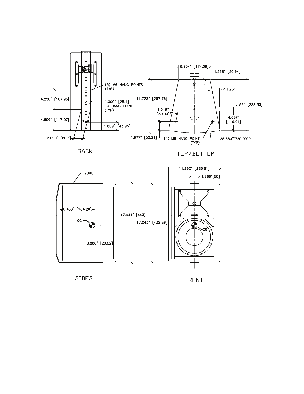
VERIS 8
VERIS 8 Notes:
The VERIS 8 has 9 x M6 hang points plus 4 x M6 rear mounting points for OmniMount™ 30 Series
inserts. The rear mounting points also accept the V-HSS handle and stand socket accessory. A steel
yoke bracket allowing 0°, 10° and 20° angles is included. For yoke mounting instructions, refer to the
supplementary instruction sheet included with this model.
Community VERIS Series - Operation and Installation Manual - Page 32
Page 33

VERIS 26
VERIS 26 Notes:
The VERIS 26 has 9 x M6 hang points plus 4 x M6 rear mounting points for OmniMount™ 30 Series
inserts. The rear mounting points also accept the V-HSS handle and stand socket accessory. A steel
yoke bracket allowing 0°, 10° and 20° angles is included. For yoke mounting instructions, refer to the
supplementary instruction sheet included with this model.
Community VERIS Series - Operation and Installation Manual - Page 33
Page 34

VERIS 28
VERIS 28 Notes:
The VERIS 28 has 9 x M6 hang points, 4 x M6 rear mounting points to accept the V-HSS handle and
stand socket accessory, plus 4 x M8 rear mounting points for OmniMount™ 60 Series inserts. A steel
yoke bracket allowing 0°, 10° and 20° angles is included. For yoke mounting instructions, refer to the
supplementary instruction sheet included with this model.
Community VERIS Series - Operation and Installation Manual - Page 34
Page 35

VERIS 12
VERIS 12 Notes:
The VERIS 12 has a total of 13 x M10 hang points plus 4 x M8 rear mounting points for OmniMount™
60 Series inserts.
Community VERIS Series - Operation and Installation Manual - Page 35
Page 36

VERIS 15
VERIS 15 Notes:
The VERIS 15 has a total of 13 x M10 hang points plus 4 x M8 rear mounting points for OmniMount™
60 Series inserts.
Community VERIS Series - Operation and Installation Manual - Page 36
Page 37

VERIS 32
VERIS 32 Notes:
The VERIS 32 has a total of 13 x M10 hang points plus 4 x M8 rear mounting points for OmniMount™
60 Series inserts.
Community VERIS Series - Operation and Installation Manual - Page 37
Page 38

VERIS 35
VERIS 35 Notes:
The VERIS 35 has a total of 13 x M10 hang points plus 4 x M8 rear mounting points for OmniMount™
60 Series inserts.
Community VERIS Series - Operation and Installation Manual - Page 38
Page 39

VERIS 210S
VERIS 210S Notes:
The VERIS 210S subwoofer has a total of 8 x M10 hang points, 4 on each side.
Community VERIS Series - Operation and Installation Manual - Page 39
Page 40

VERIS 212S
VERIS 212S Notes:
The VERIS 212S subwoofer has a total of 8 x M10 hang points, 4 on each side.
Community VERIS Series - Operation and Installation Manual - Page 40
Page 41

SERVICING VERIS LOUDSPEAKERS
Any driver service required is done from the front of the enclosure by removing the screws
around the edge of the grille. Crossovers and connections may be accessed by removing
the rear connector plate. For warranty repair, contact Community directly or ask us for the
location of your nearest Authorized Service Center.
WARRANTY INFORMATION AND SERVICE
Transferable Warranty "(Limited)” Valid in the USA Only
Community loudspeaker systems are warranted in the USA to be free from manufacturing
defects in materials and workmanship for a period of five years, as determined by one of
the following two methods, whichever is longer:
Starting from the date of retail purchase, as noted on the sales receipt from an
authorized Community dealer,
OR
Starting from the date of manufacture, determined by the serial number, if the
sales receipt is not available.
This warranty applies to the product; therefore, the remainder of the warranty period will
be automatically transferred to any subsequent owner.
This warranty applies only to failure of a Community loudspeaker caused by defects in
materials and workmanship during the stated warranty period. It does not apply to a unit
that has been subjected to abuse, accident, modification, improper handling/installation, or
repairs made without factory authorization or by anyone other than authorized Community
Field Service Stations. This warranty is void if the serial number has been defaced, altered
or removed.
Products covered by this warranty will be repaired or replaced at the option of Community,
without charge for materials or labor, provided all the terms of this warranty have been
met.
Obtaining Warranty Service
Warranty service may be obtained from the factory, or from an authorized Field Service
Station.
To obtain factory or field warranty service for products purchased in the United States,
return the product for inspection to the address below, freight prepaid, in the original
packaging. If the original packaging is not available, call or write Community Warranty
Service to obtain proper packaging materials or hand carry the product to the nearest Field
Service Station.
Factory Service Center:
Community Warranty Service
333 East Fifth Street
Chester, PA 19013-4511 USA
Field Service Station:
Call (610) 876-3400 for the nearest Authorized Field Service Station
Community VERIS Series - Operation and Installation Manual - Page 41
Page 42

For factory service, please call (610) 876-3400 for a Return Authorization (R/A) number
before shipping. The following information must be included in the package:
Owner’s complete name, daytime phone number, return street address and return
authorization number.
The serial number of the product being returned and a copy of the retail sales
receipt, if possible.
A complete description of the problem(s) experienced, including a brief description
of how the equipment is being used and with what brand, model and output power
of amplifier.
Upon receipt, the service center will determine if the problem is covered under warranty. If
covered under this warranty, the product will be repaired or replaced, at Community’s
option, and returned to the owner freight prepaid. If the problem is not covered under this
warranty, the owner will be notified of the problem with an estimate of the repair costs.
Consequential and Incidental Damages: Community shall not be liable for any
consequential or incidental damages including, without limitation, injury to persons,
property, or loss of use. Some states do not allow the exclusion or limitations of
consequential or incidental damages, so the above limitations and exclusions may not
apply.
This Community warranty is not extended by the length of time which an owner is deprived
of the use of the product. Repairs and replacement parts provided under the terms of this
warranty shall carry only the remaining portion of the warranty.
Community reserves the right to change the design of any product from time to time,
without notice and with no obligation to make corresponding changes in products previously
manufactured.
While this warranty gives specific legal rights, there may also be other rights that vary from
state to state. No action to enforce this warranty shall be permitted ninety days after
expiration of the warranty period.
Warranty Information and Service for Countries Other Than the USA
To obtain specific warranty information and available service locations for countries other
than the United States of America, contact the authorized Community Distributor for your
specific country or region.
SUMMING THINGS UP
VERIS loudspeakers and accessories are intelligently designed to provide you with effective
solutions for common and not-so-common sound reinforcement problems. These greatlooking and superb-sounding building blocks can be utilized in a wide variety of ways. By
giving careful consideration to your application needs, and taking the time to properly
position, focus, adjust, and equalize your system, VERIS products will provide years of
satisfying service. If questions or special needs arise at any time, the professional staff at
Community will be happy to offer experienced technical advice to assist you.
Community VERIS Series - Operation and Installation Manual - Page 42
∫
Page 43

NOTES
Community VERIS Series - Operation and Installation Manual - Page 43
Page 44

Community Professional Loudspeakers
333 East Fifth Street, Chester, PA 19013-4511 USA
Tel: 1-(610) 876-3400 | Fax: 1-(610) 874-0190
www.communitypro.com
© 2009 All Rights Reserved
20090804
Page 45

VERIS 6/8/26/28
)
E
Yoke Mounting Bracket
The compact VERIS models VERIS 6, VERIS 8, VERIS 26 and VERIS 28 conveniently include a yoke-style
mounting bracket for horizontal or vertical mounting, plus optional stand-offs to achieve a 10° or 20°
downward vertical tilt. The yoke bracket is fitted with a series of mounting holes as shown in Figure 1 to
allow the installer to vary the distance from the enclosure to the mounting surface in order to suit the
requirements of the installation. It is engineered to provide a high margin of safety when supporting a
VERIS 6/8/26/28 loudspeaker. Yokes are manufactured of steel, covered with a durable powder-coat finish,
and are included with the loudspeaker in either black or white to match the color of the enclosure.
Figure 1: VERIS Loudspeaker and Mounting Yoke
SERIES OF YOKE MOUNTING HOLES TO
VA R Y THE DISTANCE OF THE ENCLOSURE
TO THE MOUNTIN G SURFACE
VERIS 8
LOUDSPEAKER
Warning: VERIS rigging fittings are rated at a Working Load Limit of 100 lbs (45 kg) with a 10:1
safety margin. No single rigging fitting should ever be subjected to a load that is greater than 50
lbs. When multiple enclosures are suspended one above the other, it is the installer’s responsibility
to insure that the combined weight load does not exceed the Working Load Limit on any one rigging fitting.
This is particularly important if the enclosures are angled steeply downward (or upward), as most or all of
the weight may be supported by the rear (or front) points only. Failure to heed this warning could result in
injury or death!
“LONG CORNER”
OF YOKE
10° OR 20° METAL STAND-OFF
(FOR DOWNWARD VERTICAL TILT
YOKE BRACKET
“SHORT CORNER”
OF YOK
Page 46

]
Each VERIS 6, VERIS 8, VERIS 26 and VERIS 28 loudspeaker includes an optional U-shaped 10° metal standoff for vertical mounting of the enclosure at a 10° downward tilt and a 20° metal stand-off for vertical
mounting of the enclosure at a 20° downward tilt. If your installation requires a downward vertical tilt,
select the appropriate stand-off. When placed in the “U” position, the 10° stand-off has a shorter base than
the 20° stand-off.
Figure 2: Metal Stand-Off Dimensions
SLOT .413" [10.5] WIDE
X 1.595" [40.5] LONG
1.969" [50]
5°
(TYP)
1.500" [38.1]
1.969" [50]
.985" [25]
1.150" [29.21]
.985" [25]
2.162" [54.9]
1.150" [29.21]
BOTH ENDS
10° Metal Stand-Off
SLOT .413" [10.5] WIDE
X 1.595" [40.5] LONG
10°
(TYP)
2.162" [54.9
BOTH ENDS
20° Metal Stand-Off
3.00" [76.2]
NOTE:
0.413" HOLES/SLOTS ACCEPT 3/8" AND 10MM FASTENERS
When placed in the “U” position, the 10° stand-off has a shorter
base than the 20° stand-off
VERIS 6/8/26/28 Yoke Mounting Bracket Instruction Guide Page 2
Page 47

When placed on its side, the mounting yoke is asymmetrical. The yoke bracket has a discernable “long
corner” (10°) and short corner (20°) as depicted in Figure 3 below. For installations where a 10 or 20
degree downward vertical tilt is desired using one of the metal stand-offs, pay special attention to the
orientation of the yoke in relation to the “long corner” and “short corner” as shown in the assembly diagrams
in this instruction guide.
Figure 3: Mounting Yoke — Side View
Short Corner
Long Corner
20°
The hardware required to attach the yoke bracket and optional stand-offs to the loudspeaker is included. No
additional hardware is provided to attach the yoke bracket to the mounting surface. Such hardware must be
supplied by the installer and should be sized and rated for the weight load of the loudspeaker, keeping in
mind that additional torque load may occur when focusing the loudspeaker within the yoke assembly. The
installer is solely responsible for determining if the mounting surface is capable of safely supporting the
weight load of the loudspeaker, for selecting appropriate hardware for the installation, and for using the yoke
mounting bracket correctly and safely.
Assembling the yoke and/or optional stand-offs to the VERIS loudspeaker is relatively straightforward. There
are four mounting options for each loudspeaker:
Horizontal 0° mounting
Vertical 0° mounting
Vertical 10° downward tilt mounting
Vertical 20° downward tilt mounting
Verify your loudspeaker model, choose your mounting option, and then follow the appropriate assembly
diagram on the following pages in this instruction guide.
10°
VERIS 6/8/26/28 Parts List
Loudspeaker System (1) M6 x 30mm Hex Bolt (2)
Operation Manual (1) M10 x 30mm Hex Bolt (1)
Warranty Card (1) M10 Hex Nut (1)
Metal Yoke Mounting Bracket (1) 6mm Lock Washer (2)
10° Metal Stand-off (1) 6mm Flat Washer (2)
20° Metal Stand-off (1) 10mm Lock Washer (1)
Rubber Washer (2) 10mm Flat Washer (2)
The installer must supply all other hardware for the installation.
CAUTION: All rigging fittings must be fitted with either optional mounting hardware or they must
remain sealed with the flat-head Allen screws that come installed in the enclosure.
VERIS 6/8/26/28 Yoke Mounting Bracket Instruction Guide Page 3
Page 48

VERIS 6
Figure 4: VERIS 6 Mounting Yoke Dimensions
15.944" [404.98]
9.374" [238.11]
1.879” [47.73]
20°
.591" [15] (TYP)
2.309" [58.64]
2.899" [73.65]
5.112" [129.85]
11.635" [295.54]
9.004" [228.69]
6.940" [176.29]
(2 ) HOLES
.413" [10.5]
DIA
7.972" [202.49]
11.045" [280.54]
3.879" [98.53]
.512"
13mm
DIA
HOLE
10°
(3) SLOTS .413" [10.5] WIDE
X 1.595" [40.5] LONG
1.969" [50]
(2) SLOTS .413" [10.5] WIDE
X .610" [15.5] LONG
(4) HOLES .256" [6.5] DIA
NOTE:
0.256" HOLES ACCEPT 1/4" AND 6MM FASTENERS
0.413" HOLES/SLOTS ACCEPT 3/8" AND 10MM FASTENERS
0.512" HOLES ACCEPT 1/2" AND 12MM FASTENERS
VERIS 6/8/26/28 Yoke Mounting Bracket Instruction Guide Page 4
Page 49

VERIS 6
Figure 5: VERIS 6 Yoke — Horizontal Mounting Assembly
M6 x 30mm HEX BOLT
6mm LOCK WASHER
6mm FLAT WASHER
BLACK
RUBBER
WASHER
6mm FLAT WASHER
6mm LOCK WASHER
M6 x 30mm HEX BOLT
BLACK RUBBER WASHER
YOKE
Figure 6: VERIS 6 Yoke — Vertical Mounting Assembly
M6 x 30mm HEX BOLT
6mm LOCK WASHER
6mm FLAT WASHER
BLACK RUBBER WASHER
BLACK
RUBBER
WASHER
YOKE
6mm FLAT WASHER
6mm LOCK WASHER
M6 x 30 mm HEX BOLT
VERIS 6/8/26/28 Yoke Mounting Bracket Instruction Guide Page 5
Page 50

F
VERIS 6
Figure 7: VERIS 6 Yoke — Yoke Orientation for Downward Vertical Tilt Mounting
20°
NOTE ORIENTATION
OF YOKE
20° METAL STAND-OFF
Figure 8: VERIS 6 Yoke — 10° Downward Vertical Tilt Mounting Assembly
10°
NOTE ORIENTATION
OF YOKE
10° METAL STAND-OF
M6 x 30mm HEX BOLT
6mm LOCK WASHER
6mm FLAT WASHER
BLACK RUBBER WASHER
10mm FLAT WASHER
BLACK
RUBBER
WASHER
6mm FLAT WASHER
M10 HEX NUT
10mm LOCK WASHER
10° METAL STAND-OFF
YOKE
10mm FLAT WASHER
M10 x 30mm HEX BOLT
Note the orientation of the
yoke with the “long corner” at
the bottom, and the correct
slot on the yoke onto which to
connect the 10° metal standoff, in order to achieve a 10°
downward vertical tilt.
6mm LOCK WASHER
M6 x 30mm HEX BOLT
VERIS 6/8/26/28 Yoke Mounting Bracket Instruction Guide Page 6
Page 51

VERIS 6
Figure 9: VERIS 6 Yoke — 20° Downward Vertical Tilt Mounting Assembly
M6 x 30mm HEX BOLT
6mm LOCK WASHER
6mm FLAT WASHER
BLACK RUBBER WASHER
M10 HEX NUT
10mm LOCK WASHER
10mm FLAT WASHER
20° METAL STAND-OFF
BLACK
RUBBER
WASHER
YOKE
6mm FLAT WASHER
6mm LOCK WASHER
M6 x 30mm HEX BOLT
10mm FLAT WASHER
M10 x 30mm LONG
HEX BOLT
Note the orientation of the
yoke with the “short corner”
at the bottom, and the correct
slot on the yoke onto which to
connect the 20° metal standoff, in order to achieve a 20°
downward vertical tilt.
VERIS 6/8/26/28 Yoke Mounting Bracket Instruction Guide Page 7
Page 52

]
VERIS 8
10.324" [262.24]
Figure 10: VERIS 8 Mounting Yoke Dimensions
17.441" [443]
20°
.591" [15] (TYP)
(2) SLOTS .413" [10.5] WIDE
X .610" [15.5] LONG
2.309" [58.64]
2.899" [73.65]
5.112" [129.85]
1.879" [47.73]
13.132" [333.56]
10.329" [262.36]
7.689" [195.3]
.413"
10.5mm
DIA
HOLE
.512"
13mm
DIA
HOLE
3.879" [98.53]
10°
(4) SLOTS .413" [10.5 ] WIDE
X 1.595" [40.5] LONG
1.969" [50
(4) .256" [6.5] DIA HOLES
8.721" [221.5]
12.542" [318.56]
NOTE:
0.256" HOLES ACCEPT 1/4" AND 6MM FASTENERS
0.413" HOLES/SLOTS ACCEPT 3/8" AND 10MM FASTENERS
0.512" HOLES ACCEPT 1/2" AND 12MM FASTENERS
VERIS 6/8/26/28 Yoke Mounting Bracket Instruction Guide Page 8
Page 53

R
M
VERIS 8
Figure 11: VERIS 8 Yoke — Horizontal Mounting Assembly
6 x 30mm HEX BOLT
6mm LOCK WASHER
6mm FLAT WASHER
BLACK
RUBBER
WASHER
YOKE
BLACK RUBBER WASHER
6mm FLAT WASHER
6mm FLAT WASHE
M6 x 30mm HEX BOLT
Figure 12: VERIS 8 Yoke — Vertical Mounting Assembly
M6 x 30mm HEX BOLT
6mm LOCK WASHER
6mm FLAT WASHER
BLACK RUBBER WASHER
BLACK
RUBBER
WASHER
YOKE
6mm FLAT WASHER
6mm LOCK WASHER
M6 x 30mm HEX BOLT
VERIS 6/8/26/28 Yoke Mounting Bracket Instruction Guide Page 9
Page 54

T
VERIS 8
Figure 13: VERIS 8 Yoke — Yoke Orientation for Downward Vertical Tilt Mounting
10°
20°
NOTE ORIENTATION
OF YOKE
NOTE ORIENTATION
OF YOKE
20° METAL STAND-OFF
10° METAL STAND-OFF
Figure 14: VERIS 8 Yoke — 10° Downward Vertical Tilt Mounting Assembly
M6 x 30mm HEX BOLT
6mm LOCK WASHER
6mm FLAT WASHER
BLACK RUBBE R WASHER
M10 HEX NUT
10mm LOCK WASHER
10mm FLAT WASHER
10mm FLAT WASHER
M10 x 30mm LONG HEX BOL
10° METAL STAND-OFF
BLACK
RUBBER
WASHER
Note the orientation of the
yoke with the “long corner” at
the bottom, and the correct
YOKE
6mm FLAT WASHER
6mm LOCK WASHER
M6 x 30mm HEX BOLT
VERIS 6/8/26/28 Yoke Mounting Bracket Instruction Guide Page 10
slot on the yoke onto which to
connect the 10° metal standoff, in order to achieve a 10°
downward vertical tilt.
Page 55

T
VERIS 8
Figure 15: VERIS 8 Yoke — 20° Downward Vertical Tilt Mounting Assembly
M6 x 30mm HEX BOLT
6mm LOCK WASHER
6mm FLAT WASHER
BLACK RUBBER WASHER
M10 HEX NUT
BLACK
RUBBER
WASHER
10mm LOCK WASHER
10mm FLAT WASHER
10mm FLAT WASHER
M10 x 30mm LONG HEX BOL
20° METAL STAND-OFF
6mm FLAT WASHER
6mm LOCK WASHER
M6 x 30mm HEX BOLT
YOKE
Note the orientation of the
yoke with the “short corner”
at the bottom, and the correct
slot on the yoke onto which to
connect the 20° metal standoff, in order to achieve a 20°
downward vertical tilt.
VERIS 6/8/26/28 Yoke Mounting Bracket Instruction Guide Page 11
Page 56

X
VERIS 26
Figure 16: VERIS 26 Mounting Yoke Dimensions
9.400" [238.76]
1.912" [48.56]
23.031" [584.99]
3.915" [99.45]
20°
2.934" [74.53]
(2) SLOTS
.413" [10.5] WIDE
.610" [15.5] LONG
2.722" [69.14]
5.147" [130.73]
15.854" [402.7]
11. 5 16" [292.5]
7.360" [186.94]
9.893" [251.29]
18.706" [475.13]
.512"
13mm
DIA
HOLE
10°
(7) SLOTS .413" [10.5] WIDE
X 1.595" [40.5] LONG
(4) .256" [6.5}
DIA HOLES
1.969" [50]
13.138" [333.7]
18.067 " [458.9]
NOTE:
0.256" HOLES ACCEPT 1/4" AND 6MM FASTENERS
0.413" HOLES/SLOTS ACCEPT 3/8" AND 10MM FASTENERS
0.512" HOLES ACCEPT 1/2" AND 12MM FASTENERS
VERIS 6/8/26/28 Yoke Mounting Bracket Instruction Guide Page 12
Page 57
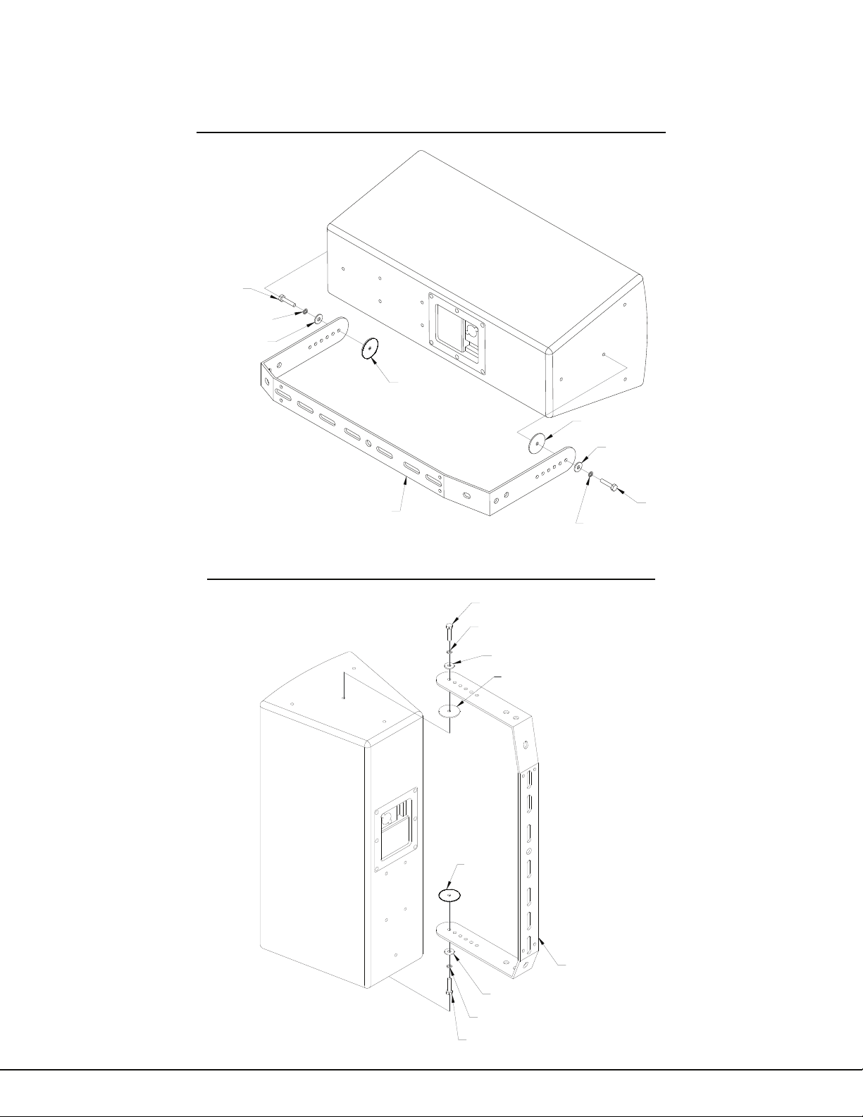
VERIS 26
Figure 17: VERIS 26 Yoke — Horizontal Mounting Assembly
M6 x 30mm HEX BOLT
6mm LOCK WASHER
6mm FLAT WASHER
BLACK
RUBBER
WASHER
BLACK RUBBER WASHER
6mm FLAT WASHER
YOKE
6mm LOCK WASHER
Figure 18: VERIS 26 Yoke — Vertical Mounting Assembly
M6 x 30mm HEX BOLT
6mm LOCK WASHER
6mm FLAT WASHER
BLACK RUBBER WASHER
M6 x 30mm HEX BOLT
BLACK
RUBBER
WASHER
YOKE
6mm FLAT WASHER
6mm LOCK WASHER
M6 x 30mm HEX BOLT
VERIS 6/8/26/28 Yoke Mounting Bracket Instruction Guide Page 13
Page 58

F
VERIS 26
Figure 19: VERIS 26 Yoke — Yoke Orientation for Downward Vertical Tilt Mounting
20°
NOTE ORIENTATION
OF YOKE
10°
NOTE ORIENTATION
OF YOKE
20° METAL STAND-OFF
10° METAL STAND-OF
Figure 20: VERIS 26 Yoke — 10° Downward Vertical Tilt Mounting Assembly
M6 x 30mm HEX BOLT
6mm LOCK WASHER
6mm FLAT WASHER
BLACK RUBBER WASHER
M10 HEX NUT
10mm LOCK WASHER
10mm FLAT WASHER
10mm FLAT WASHER
M10 x 30mm HEX BOLT
BLACK
RUBBER
WASHER
10° METAL STAND-OFF
Note the orientation of the
YOKE
yoke with the “long corner” at
the bottom, and the correct
slot on the yoke onto which to
6mm FLAT WASHER
6mm LOCK WASHER
M6 x 30mm HEX BOLT
connect the 10° metal standoff, in order to achieve a 10°
downward vertical tilt.
VERIS 6/8/26/28 Yoke Mounting Bracket Instruction Guide Page 14
Page 59

VERIS 26
Figure 21: VERIS 26 Yoke — 20° Downward Vertical Tilt Mounting Assembly
M6 x 30mm HEX BOLT
6mm LOCK WASHER
6mm FLAT WASHER
BLACK RUBBER WASHER
M10 HEX NUT
BLACK
RUBBER
WASHER
YOKE
6mm FLAT WASHER
6mm LOCK WASHER
M6 x 30mm HEX BOLT
10mm LOCK WASHER
10mm FLAT WASHER
10mm FLAT WASHER
M10 x 30mm HEX BOLT
20° METAL STAND-OFF
Note the orientation of the
yoke with the “short corner”
at the bottom, and the correct
slot on the yoke onto which to
connect the 20° metal standoff, in order to achieve a 20°
downward vertical tilt.
VERIS 6/8/26/28 Yoke Mounting Bracket Instruction Guide Page 15
Page 60

E
VERIS 28
10.364" [263.24]
Figure 22: VERIS 28 Mounting Yoke Dimensions
26.023" [660.99]
1.912" [48.56]
3.925" [99.7]
20°
5.152" [130.85]
2.939" [74.65]
5.020" [127.5]
15.010" [381.25]
12.283" [311.98]
9.577" [243.26]
7.364" [187.06]
11.251" [285.77]
13.741" [349.01]
17.035" [432.69]
21.084" [535.54]
19.060" [484.11]
.413"
10.5mm
DIA
HOLE
.512"
13mm
DIA
HOLE
10°
(8 ) SLOTS .413" [10.5] WIDE
X 1.595" [40.5] LONG
(2) SLOTS .413" [10.5 ] WID
X .610" [15.5] LONG
1.969" [50]
(4 ) .256" [6.5]
DIA HOLES
21.004" [533.49]
NOTE:
0.256" HOLES ACCEPT 1/4" AND 6MM FASTENERS
0.413" HOLES/SLOTS ACCEPT 3/8" AND 10MM FASTENERS
0.512" HOLES ACCEPT 1/2" AND 12MM FASTENERS
VERIS 6/8/26/28 Yoke Mounting Bracket Instruction Guide Page 16
Page 61

M
R
VERIS 28
Figure 23: VERIS 28 Yoke — Horizontal Mounting Assembly
6 x 30mm HEX BOLT
6mm LOCK WASHER
6mm FLAT WA SHER
BLACK
RUBBER
WASHER
BLACK
RUBBER
WASHER
6mm FLAT WASHER
YOKE
6mm LOCK WAS HE R
M6 x 30mm HEX BOLT
Figure 24: VERIS 28 Yoke — Vertical Mounting Assembly
M6 x 30mm HEX BOLT
6mm LOCK WASHER
6mm FLAT WASHER
BLACK RUBBER WASHE
BLACK
RUBBER
WASHER
YOKE
6mm FLAT WASHER
6mm LOCK WASHER
M6 x 30mm HEX BOLT
VERIS 6/8/26/28 Yoke Mounting Bracket Instruction Guide Page 17
Page 62

F
T
VERIS 28
Figure 25: VERIS 28 Yoke — Yoke Orientation for Downward Vertical Tilt Mounting
NOTE ORIENTATION
NOTE ORIENTATION
OF YOKE
OF YOKE
20°
10°
10° METAL STAND-OF
20° METAL STAND-OFF
Figure 26: VERIS 28 Yoke — 10° Downward Vertical Tilt Mounting Assembly
M6 x 30mm HEX BOLT
6mm LOCK WASHER
6mm FLAT WASHE R
BLACK RUBBER WASHER
M10 HEX NUT
10mm LOCK WAS HER
10mm FLAT WASHER
10mm FLAT WASHE R
M10 x 30mm HEX BOL
10° METAL STAND-OFF
Note the orientation of the
YOKE
yoke with the “long corner” at
the bottom, and the correct
slot on the yoke onto which to
6mm FLAT WASHE R
6mm LOCK WASHER
M6 x 30mm HEX BOLT
connect the 10° metal standoff, in order to achieve a 10°
downward vertical tilt.
VERIS 6/8/26/28 Yoke Mounting Bracket Instruction Guide Page 18
Page 63

T
VERIS 28
Figure 27: VERIS 28 Yoke — 20° Downward Vertical Tilt Mounting Assembly
M6 x 30mm HEX BOLT
6mm LOCK WASHER
6mm FLAT WASHER
BLACK RUBBER WASHER
M10 HEX NUT
10mm FLAT WASHER
BLACK
RUBBER
WASHER
6mm FLAT WASHER
6mm LOCK WASHER
M6 x 30mm HEX BOLT
10mm LOCK WASHER
20° METAL STAND-OFF
10mm FLAT WASHER
M10 x 30mm HEX BOL
YOKE
Note the orientation of the
yoke with the “short corner”
at the bottom, and the correct
slot on the yoke onto which to
connect the 20° metal standoff, in order to achieve a 20°
downward vertical tilt.
VERIS 6/8/26/28 Yoke Mounting Bracket Instruction Guide Page 19
Page 64

VERIS 6/8/26/28 Yoke Assembly Instructions
1. Assembling the yoke and/or optional stand-offs to the VERIS loudspeaker is relatively straightforward.
There are four mounting options for each loudspeaker:
Horizontal 0° mounting
Vertical 0° mounting
Vertical 10° downward tilt mounting
Vertical 20° downward tilt mounting
Choose your mounting option and then follow the appropriate assembly diagram in this instruction guide.
2. For vertical mounting of the loudspeaker at a downward tilt, select either the 10° or 20° metal stand-off
and attach it to the yoke by using the M10 x 30mm hex bolt, two flat washers, a lockwasher and M10 hex
nut, as depicted in the appropriate assembly diagram for your loudspeaker model. Pay careful attention to
the orientation of the yoke (short corner and long corner) in relation to the enclosure and the correct slot on
the yoke into which the stand-off should be connected. The orientation of the yoke and the correct slot
position varies by loudspeaker model. For horizontal and vertical mounting at 0°, the stand-offs are not
needed.
3. Before installing the loudspeaker in the yoke, the yoke (or yoke and metal stand-off assembly) should
first be attached to the mounting surface. No hardware is provided for this purpose. Such hardware must
be supplied by the installer, and should be rated for the weight load of the enclosures. The installer is solely
responsible for determining if the hardware used to mount the yoke is adequately sized and rated, and if the
structure to which it is attached is capable of safely supporting the weight load of the enclosure.
4. Installing the loudspeaker in the yoke is straightforward. First remove two of the flat-head Allen screws
that come installed in the loudspeaker, one each in the center of the top and bottom panels.
5. A series of holes are provided to allow the enclosure to be positioned at varying distances from the
mounting surface. Note that the closer the yoke is to the rear of the enclosure, the less the range of motion
will be. Determine which pair of holes will be used, making sure to leave enough clearance for the
loudspeaker wire and connector(s).
6. Next, fit each of the two M6 x 30mm bolts with a lock washer and a flat washer. Place the two large
rubber washers between the yoke and the loudspeaker, then pass each bolt through the yoke bracket and
the rubber washer into the loudspeaker’s rigging fitting. Tighten the fasteners until snug. After focusing the
loudspeaker in the desired position, the bolts should be tightened to a torque of approximately 12 to 15 footpounds. Do not overtighten!
Caution: Installation of loudspeakers should only be performed by trained and
qualified personnel. It is strongly recommended that a licensed and certified
professional structural engineer approve the mounting design.
Community Professional Loudspeakers · 333 East Fifth Street, Chester, PA 19013 USA
Phone (610) 876-3400 · Fax (610) 874-0190 · www.communitypro.com
V6/8/26/28IG 20090727
 Loading...