

Page 1
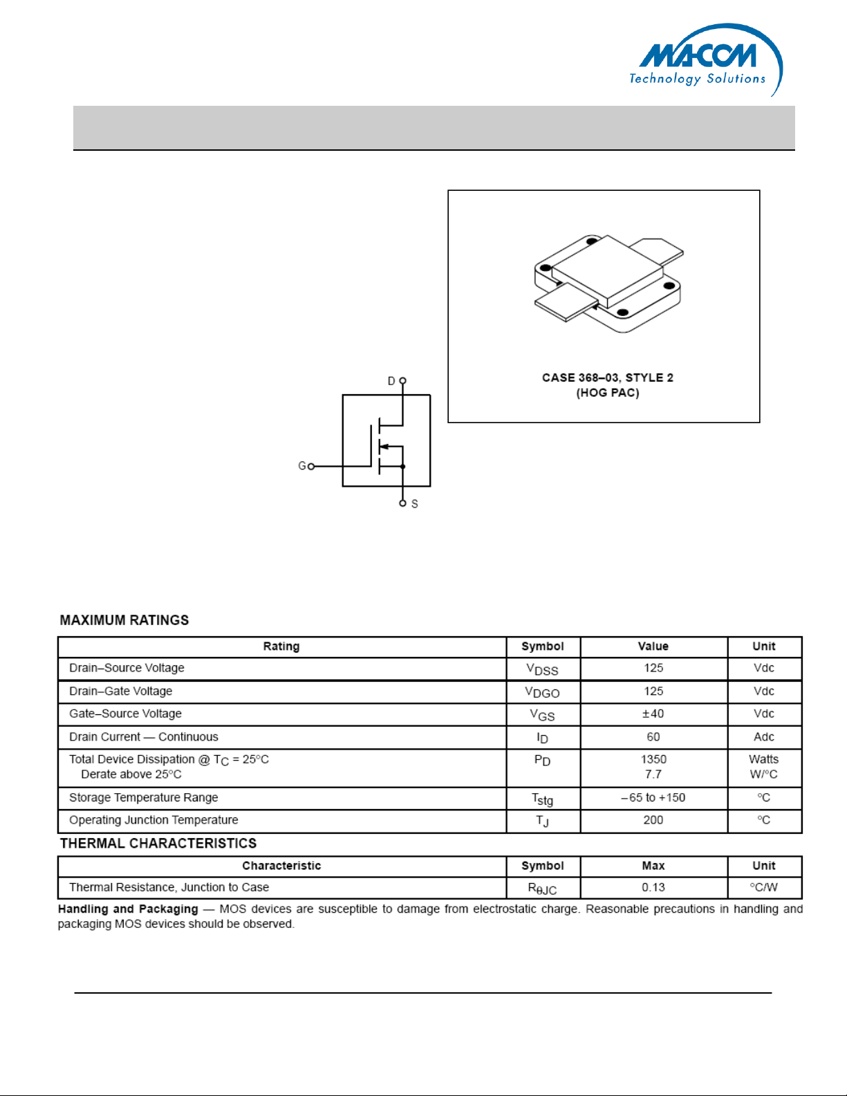
MRF154
Broadband RF Power MOSFET
600W, to 80MHz, 50V
Designed primarily for linear large signal output stages in
the 2.0 to 100 MHz frequency range.
N–Channel enhancement mode MOSFET
• Specified 50 volts, 30 MHz characteristics
Output power = 600 watts
Power gain = 17 dB (typ.)
Efficiency = 45% (typ.)
M/A-COM Products
Released - Rev. 07.07
Product Image
1
ADVANCED: Data Sheets contain information regarding a product M/A-COM Technology Solutions
is considering for development. Performance is based on target specifications, simulated results,
and/or prototype measurements. Commitment to develop is not guaranteed.
PRELIMINARY: Data Sheets contain information regarding a product M/A-COM Technology
Solutions has under development. Performance is based on engineering tests. Specifications are
typical. Mechanical outline has been fixed. Engineering samples and/or test data may be available.
Commitment to produce in volume is not guaranteed.
• North America Tel: 800.366.2266 / Fax: 978.366.2266
• Europe Tel: 44.1908.574.200 / Fax: 44.1908.574.300
• Asia/Pacific Tel: 81.44.844.8296 / Fax: 81.44.844.8298
Visit www.macomtech.com for additional data sheets and product information.
M/A-COM Technology Solutions Inc. and its affiliates reserve the right to make
changes to the product(s) or information contained herein without notice.
Page 2
MRF154
Broadband RF Power MOSFET
600W, to 80MHz, 50V
M/A-COM Products
Released - Rev. 07.07
2
ADVANCED: Data Sheets contain information regarding a product M/A-COM Technology Solutions
is considering for development. Performance is based on target specifications, simulated results,
and/or prototype measurements. Commitment to develop is not guaranteed.
PRELIMINARY: Data Sheets contain information regarding a product M/A-COM Technology
Solutions has under development. Performance is based on engineering tests. Specifications are
typical. Mechanical outline has been fixed. Engineering samples and/or test data may be available.
Commitment to produce in volume is not guaranteed.
• North America Tel: 800.366.2266 / Fax: 978.366.2266
• Europe Tel: 44.1908.574.200 / Fax: 44.1908.574.300
• Asia/Pacific Tel: 81.44.844.8296 / Fax: 81.44.844.8298
Visit www.macomtech.com for additional data sheets and product information.
M/A-COM Technology Solutions Inc. and its affiliates reserve the right to make
changes to the product(s) or information contained herein without notice.
Page 3
MRF154
Broadband RF Power MOSFET
600W, to 80MHz, 50V
M/A-COM Products
Released - Rev. 07.07
3
ADVANCED: Data Sheets contain information regarding a product M/A-COM Technology Solutions
is considering for development. Performance is based on target specifications, simulated results,
and/or prototype measurements. Commitment to develop is not guaranteed.
PRELIMINARY: Data Sheets contain information regarding a product M/A-COM Technology
Solutions has under development. Performance is based on engineering tests. Specifications are
typical. Mechanical outline has been fixed. Engineering samples and/or test data may be available.
Commitment to produce in volume is not guaranteed.
• North America Tel: 800.366.2266 / Fax: 978.366.2266
• Europe Tel: 44.1908.574.200 / Fax: 44.1908.574.300
• Asia/Pacific Tel: 81.44.844.8296 / Fax: 81.44.844.8298
Visit www.macomtech.com for additional data sheets and product information.
M/A-COM Technology Solutions Inc. and its affiliates reserve the right to make
changes to the product(s) or information contained herein without notice.
Page 4

MRF154
Broadband RF Power MOSFET
600W, to 80MHz, 50V
M/A-COM Products
Released - Rev. 07.07
4
ADVANCED: Data Sheets contain information regarding a product M/A-COM Technology Solutions
is considering for development. Performance is based on target specifications, simulated results,
and/or prototype measurements. Commitment to develop is not guaranteed.
PRELIMINARY: Data Sheets contain information regarding a product M/A-COM Technology
Solutions has under development. Performance is based on engineering tests. Specifications are
typical. Mechanical outline has been fixed. Engineering samples and/or test data may be available.
Commitment to produce in volume is not guaranteed.
• North America Tel: 800.366.2266 / Fax: 978.366.2266
• Europe Tel: 44.1908.574.200 / Fax: 44.1908.574.300
• Asia/Pacific Tel: 81.44.844.8296 / Fax: 81.44.844.8298
Visit www.macomtech.com for additional data sheets and product information.
M/A-COM Technology Solutions Inc. and its affiliates reserve the right to make
changes to the product(s) or information contained herein without notice.
Page 5

MRF154
Broadband RF Power MOSFET
600W, to 80MHz, 50V
M/A-COM Products
Released - Rev. 07.07
5
ADVANCED: Data Sheets contain information regarding a product M/A-COM Technology Solutions
is considering for development. Performance is based on target specifications, simulated results,
and/or prototype measurements. Commitment to develop is not guaranteed.
PRELIMINARY: Data Sheets contain information regarding a product M/A-COM Technology
Solutions has under development. Performance is based on engineering tests. Specifications are
typical. Mechanical outline has been fixed. Engineering samples and/or test data may be available.
Commitment to produce in volume is not guaranteed.
• North America Tel: 800.366.2266 / Fax: 978.366.2266
• Europe Tel: 44.1908.574.200 / Fax: 44.1908.574.300
• Asia/Pacific Tel: 81.44.844.8296 / Fax: 81.44.844.8298
Visit www.macomtech.com for additional data sheets and product information.
M/A-COM Technology Solutions Inc. and its affiliates reserve the right to make
changes to the product(s) or information contained herein without notice.
Page 6

MRF154
Broadband RF Power MOSFET
600W, to 80MHz, 50V
M/A-COM Products
Released - Rev. 07.07
6
ADVANCED: Data Sheets contain information regarding a product M/A-COM Technology Solutions
is considering for development. Performance is based on target specifications, simulated results,
and/or prototype measurements. Commitment to develop is not guaranteed.
PRELIMINARY: Data Sheets contain information regarding a product M/A-COM Technology
Solutions has under development. Performance is based on engineering tests. Specifications are
typical. Mechanical outline has been fixed. Engineering samples and/or test data may be available.
Commitment to produce in volume is not guaranteed.
• North America Tel: 800.366.2266 / Fax: 978.366.2266
• Europe Tel: 44.1908.574.200 / Fax: 44.1908.574.300
• Asia/Pacific Tel: 81.44.844.8296 / Fax: 81.44.844.8298
Visit www.macomtech.com for additional data sheets and product information.
M/A-COM Technology Solutions Inc. and its affiliates reserve the right to make
changes to the product(s) or information contained herein without notice.
Page 7

MRF154
Broadband RF Power MOSFET
600W, to 80MHz, 50V
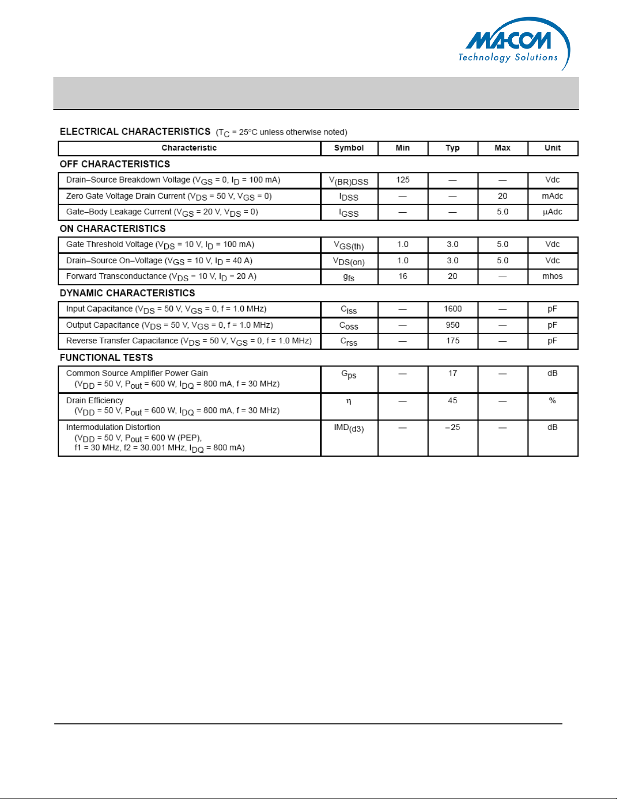
RF POWER MOSFET CONSIDERATIONS
The physical structure of a MOSFET results in capacitors
between the terminals. The metal oxide gate structure determines the capacitors from gate–to–drain (Cgd), and
gate–to–source (Cgs). The PN junction formed during the
fabrication of the RF MOSFET results in a junction capacitance from drain–to–source (Cds).
These capacitances are characterized as input (Ciss),
output (Coss) and reverse transfer (Crss) capacitances on
data sheets. The relationships between the inter–terminal
capacitances and those given on data sheets are shown
below. The
Ciss can be specified in two ways:
1.Drain shorted to source and positive voltage at the gate.
2.Positive voltage of the drain in respect to source and
zero volts at the gate. In the latter case the numbers are
lower. However, neither method represents the actual operating conditions in RF applications.
LINEARITY AND GAIN CHARACTERISTICS
In addition to the typical IMD and power gain data presented, Figure 5 may give the designer additional information on the capabilities of this device. The graph represents
the small signal unity current gain frequency at a given
drain current level. This is equivalent to fT for bipolar transistors. Since this test is performed at a fast sweep speed,
heating of the device does not occur. Thus, in normal use,
the higher temperatures may degrade these characteristics
to some extent.
DRAIN CHARACTERISTICS
One figure of merit for a FET is its static resistance in the
full–on condition. This on–resistance, VDS(on), occurs in
the linear region of the output characteristic and is specified
under specific test conditions for gate–source voltage and
drain current. For MOSFETs, VDS(on) has a positive temperature coefficient and constitutes an important design
consideration at high temperatures, because it contributes
to the power dissipation within the device.
M/A-COM Products
Released - Rev. 07.07
GATE CHARACTERISTICS
The gate of the RF MOSFET is a polysilicon material, and
is electrically isolated from the source by a layer of oxide.
The input resistance is very high — on the order of 109
ohms
— resulting in a leakage current of a few nanoamperes.
Gate control is achieved by applying a positive voltage
slightly in excess of the gate–to–source threshold voltage,
VGS(th).
Gate Voltage Rating — Never exceed the gate voltage
rating. Exceeding the rated VGS can result in permanent
damage to the oxide layer in the gate region.
Gate Termination — The gates of these devices are essentially capacitors. Circuits that leave the gate open–
circuited or floating should be avoided. These conditions
can result in turn–on of the devices due to voltage build–u p
on the input capacitor due to leakage currents or pickup.
Gate Protection — These devices do not have an internal
monolithic zener diode from gate–to–source. If gate protection is required, an external zener diode is recommended.
MOUNTING OF HIGH POWER RF
POWER TRANSISTORS
The package of this device is designed for conduction
cooling. It is extremely important to minimize the thermal
resistance between the device flange and the heat dissipator.
Since the device mounting flange is made of soft copper,
itmay be deformed during various stages of handling or
during transportation. It is recommended that the user
makes a final inspection on this before the device installation. ±0.0005, is considered sufficient for the flange bottom.
The same applies to the heat dissipator in the device
mounting area. If copper heatsink is not used, a copper
head spreader is strongly recommended between the device mounting surfaces and the main heatsink. It should be
at least 1/4, thick and extend at least one inch from the
flange edges. A thin layer of thermal compound in all interfaces is, of course, essential. The recommended torque on
the 4–40 mounting screws should be in the area of 4–5
lbs.–inch, and spring type lock washers along with flat
washers are recommended.
For die temperature calculations, the Δ temperature from a
corner mounting screw area to the bottom center of the
flange is approximately 5°C and 10°C under normal operating conditions (dissipation 150 W and 300 W respectively).
The main heat dissipater must be sufficiently large and
have low Rθ for moderate air velocity, unless liquid cooling
is employed.
7
ADVANCED: Data Sheets contain information regarding a product M/A-COM Technology Solutions
is considering for development. Performance is based on target specifications, simulated results,
and/or prototype measurements. Commitment to develop is not guaranteed.
PRELIMINARY: Data Sheets contain information regarding a product M/A-COM Technology
Solutions has under development. Performance is based on engineering tests. Specifications are
typical. Mechanical outline has been fixed. Engineering samples and/or test data may be available.
Commitment to produce in volume is not guaranteed.
• North America Tel: 800.366.2266 / Fax: 978.366.2266
• Europe Tel: 44.1908.574.200 / Fax: 44.1908.574.300
• Asia/Pacific Tel: 81.44.844.8296 / Fax: 81.44.844.8298
Visit www.macomtech.com for additional data sheets and product information.
M/A-COM Technology Solutions Inc. and its affiliates reserve the right to make
changes to the product(s) or information contained herein without notice.
Page 8

MRF154
Broadband RF Power MOSFET
600W, to 80MHz, 50V
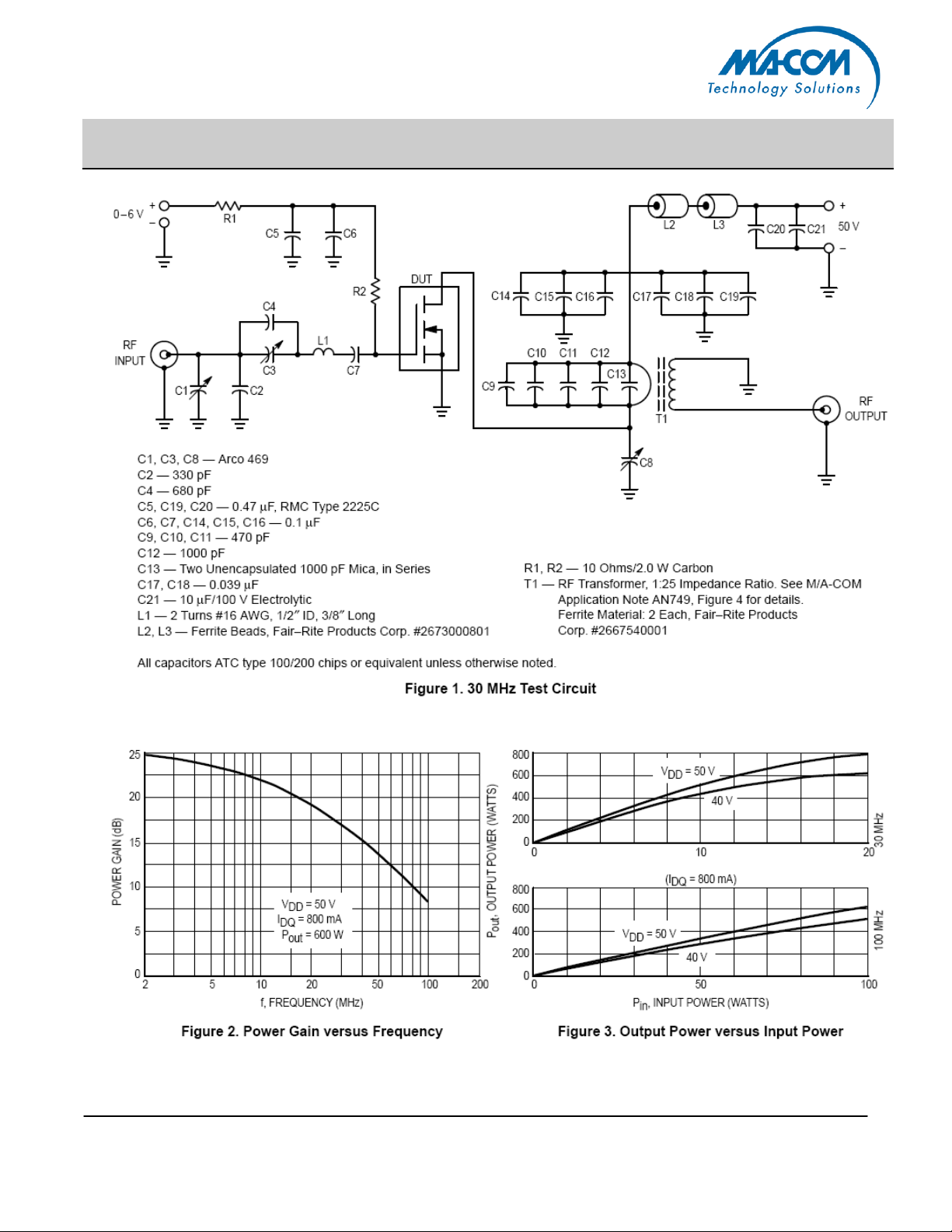
CIRCUIT CONSIDERATIONS
At high power levels (500 W and up), the circuit layout
becomes critical due to the low impedance levels an d high
RF currents associated with the output matching. Some of
the components, such as capacitors and inductors must
also withstand these currents. The component losses are
directly proportional to the operating frequency. The manufacturers
M/A-COM Products
Released - Rev. 07.07
specifications on capacitor ratings should be consulted on
these aspects prior to design.
Push–pull circuits are less critical in general, since the
ground referenced RF loops are practically eliminated, and
the impedance levels are higher for a given power output.
High power broadband transformers are also easier to design than comparable LC matching networks.
8
ADVANCED: Data Sheets contain information regarding a product M/A-COM Technology Solutions
is considering for development. Performance is based on target specifications, simulated results,
and/or prototype measurements. Commitment to develop is not guaranteed.
PRELIMINARY: Data Sheets contain information regarding a product M/A-COM Technology
Solutions has under development. Performance is based on engineering tests. Specifications are
typical. Mechanical outline has been fixed. Engineering samples and/or test data may be available.
Commitment to produce in volume is not guaranteed.
• North America Tel: 800.366.2266 / Fax: 978.366.2266
• Europe Tel: 44.1908.574.200 / Fax: 44.1908.574.300
• Asia/Pacific Tel: 81.44.844.8296 / Fax: 81.44.844.8298
Visit www.macomtech.com for additional data sheets and product information.
M/A-COM Technology Solutions Inc. and its affiliates reserve the right to make
changes to the product(s) or information contained herein without notice.
Page 9

MRF154
Broadband RF Power MOSFET
600W, to 80MHz, 50V
M/A-COM Products
Released - Rev. 07.07
9
ADVANCED: Data Sheets contain information regarding a product M/A-COM Technology Solutions
is considering for development. Performance is based on target specifications, simulated results,
and/or prototype measurements. Commitment to develop is not guaranteed.
PRELIMINARY: Data Sheets contain information regarding a product M/A-COM Technology
Solutions has under development. Performance is based on engineering tests. Specifications are
typical. Mechanical outline has been fixed. Engineering samples and/or test data may be available.
Commitment to produce in volume is not guaranteed.
• North America Tel: 800.366.2266 / Fax: 978.366.2266
• Europe Tel: 44.1908.574.200 / Fax: 44.1908.574.300
• Asia/Pacific Tel: 81.44.844.8296 / Fax: 81.44.844.8298
Visit www.macomtech.com for additional data sheets and product information.
M/A-COM Technology Solutions Inc. and its affiliates reserve the right to make
changes to the product(s) or information contained herein without notice.
 Loading...