

Page 1
FL1 LOW PASS FILTERS
Broadband amplifiers, by definition, provide little, if any, suppression of harmonic
energy. The output of the amplifier will contain harmonics of the input signal.
Thus, if direct operation into an antenna is expected, filtering of the amplifier
output is necessary to meet FCC regulations for spectral purity. A five element,
low pass filter will provide more than sufficient harmonic attenuation. The low
pass filter will attenuate signals above the desired output frequency.
Filter Design
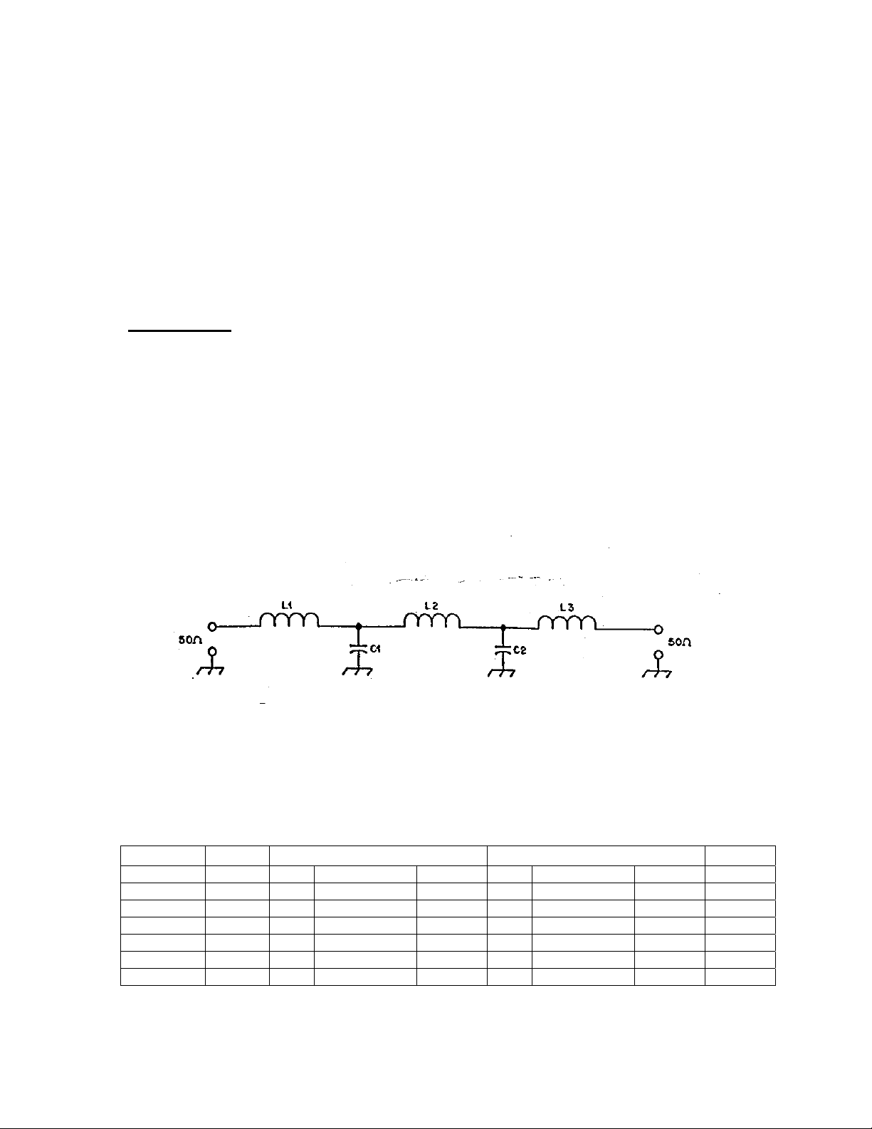
The five element, low pass filter design is derived from information contained in
the ARRL Handbook. The filter schematic is shown in Figure 1. The various
filter parameters are shown in Table 1. The capacitance values derived for C1
and C2 are not standard values for some of the filters. In order to achieve the
closest value for the filter, standard values are placed in parallel. Provision has
been made on the PC board to accommodate the parallel values. When a
capacitance value requires parallel values, the capacitors are identified as C1A
and C1B for the parallel combination of C1. C2A and C2B are the parallel
combination of C2. These combinations are shown in Table 2.
Figure 1 - FL1 Schematic Diagram
Table 1 – FL1 Filter Parameters
BAND Fcutoff L1,L3 L2 C1,C2
(meters) (MHz) (uH) No. of Turns Toroid (uH) No. of Turns Toroid (pf)
160 2.1 8.1 23 T-106-2 11.4 28 T-106-2 1653
80 4.1 4.1 16 T-106-2 5.8 20 T-106-2 847
40 7.4 2.3 12 T-106-2 3.2 14 T-106-2 470
20 14.450 1.18 9 T-106-6 1.65 11 T-106-6 240
15 21.550 0.79 7 T-106-6 1.11 8 T-106-6 161
10 29.8 0.57 6 T-106-6 0.80 7 T-106-6 117
1
Page 2
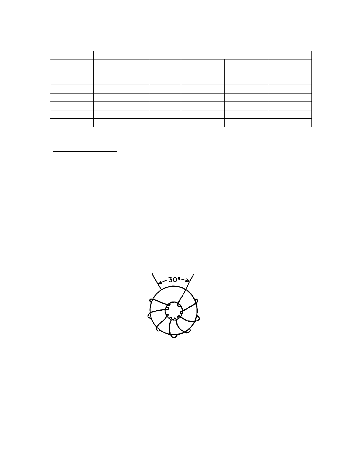
Table 2 – Parallel Capacitance Values
Desired Value Parallel Values
BAND C1, C2 C1A C1B C2A C2B
(meters) (pf) (pf) (pf) (pf) (pf)
160 1653 1500 150 1500 150
80 847 820 27 820 27
40 470 470 -- 470 -20 240 240 -- 240 -15 161 110 51 110 51
10 117 100 18 100 18
Construction Hints
The effective inductance of a toroid coil depends in part on the distributed
capacitance between the coil turns and between the ends of the winding. The
distributed capacitance should be kept as low as possible. The pictorial
illustration in Figure 2 show the inductor turns distributed uniformly around the
toroid core, but a gap of approximately 30 degrees is maintained between the
ends of the winding. This method is recommended to reduce the distributed
capacitance of the winding. The closer the ends of the winding are to one
another, the greater the unwanted capacitance. Also, in order to achieve the
desired toroid inductance, the winding should be spread over the core as shown
in Figure 2.
Figure 2 – Toroid Winding Pictorial
2
Page 3

The proper method for counting the turns on a toroidal inductor is shown in
Figure 3. The core is shown as it would appear when stood on its edge with the
narrow dimension toward the viewer. In this example, a four-turn winding has
been placed on the core.
Figure 3 – Toroid Turns Counting Pictorial
Filter Construction
The construction of the filter is fairly simple but requires some care. A
component layout pictorial is shown in Figure 4. For identification purposes, the
foil side of the PC board is the bottom. The components are placed on the
topside of the PC board and soldered on the bottom. The PC board is the same
for all frequency bands. The toroid cores are identified by the color of the core.
The T-106-2 is gray in color and the T-106-6 is yellow.
Figure 4 – Component Layout Pictorial
3
Page 4

The capacitors C1 (or C1A and C1B) and C2 (or C2A and C2B) should be
mounted on the PC board first. Refer to Table 2 for the proper values and the
component layout pictorial in Figure 4 for proper placement. Next wind the toroid
with the proper number of turns using the #18 AWG enameled wire included.
The wire should follow the contour of the core and be snug. Refer to Figure 2 for
the proper number of windings and the construction hints for the toroid winding
procedures. After winding the toroids, scrape off enough of the enamel coating
on the wire for soldering purposes. Then mount and solder the toroid to the PC
board. The toroid is mounted to the PC board using a 4-40 x ¾ inch bolt and
KEP nut with a large fiber washer. Refer to the toroid mounting pictorial in Figure
5.
Figure 5 – Toroid Mounting Pictorial
Since the filter circuit is symmetrical, the input and output can be reversed. 50
ohm coax should be used for the connections as shown in the component layout
pictorial in Figure 4. The shield of the coax should connect to the large ground
foil on the PC board. The filter should be connected as close as possible to the
output of the power amplifier. This distance should be 6 inches or less. Connect
the filter between the output of the amplifier and the antenna as shown in Figure
6. No tuning of the filter is necessary if care is exercised in the construction.
Figure 6 – Filter Installation
4
Page 5

Filter Parts List
160 Meter Filter Board Part Number FL1-160
3 each T-106-2 Toroid Cores
2 each 1500 pf Silver Mica Capacitors 500 WVDC
2 each 150 pf Silver Mica Capacitors 500 WVDC
3 each 60 inches #18 AWB enameled wire
3 each 4-40 x ¾” bolt
3 each 4-40 Kep Nut
3 each Fiber Washer
1 each PC Board (FL1)
80 Meter Filter Board Part Number FL1-80
3 each T-106-2 Toroid Cores
2 each 820 pf Silver Mica Capacitors 500 WVDC
2 each 27 pf Silver Mica Capacitors 500 WVDC
3 each 40 inches #18 AWB enameled wire
3 each 4-40 x ¾” bolt
3 each 4-40 Kep Nut
3 each Fiber Washer
1 each PC Board (FL1)
40 Meter Filter Board Part Number FL1-40
3 each T-106-2 Toroid Cores
2 each 470 pf Silver Mica Capacitors 500 WVDC
3 each 28 inches #18 AWB enameled wire
3 each 4-40 x ¾” bolt
3 each 4-40 Kep Nut
3 each Fiber Washer
1 each PC Board (FL1)
20 Meter Filter Board Part Number FL1-20
3 each T-106-6 Toroid Cores
2 each 240 pf Silver Mica Capacitors 500 WVDC
3 each 22 inches #18 AWB enameled wire
3 each 4-40 x ¾” bolt
3 each 4-40 Kep Nut
3 each Fiber Washer
1 each PC Board (FL1)
5
Page 6

15 Meter Filter Board Part Number FL1-15
3 each T-106-6 Toroid Cores
2 each 110 pf Silver Mica Capacitors 500 WVDC
2 each 51 pf Silver Mica Capacitors 500 WVDC
3 each 18 inches #18 AWB enameled wire
3 each 4-40 x ¾” bolt
3 each 4-40 Kep Nut
3 each Fiber Washer
1 each PC Board (FL1)
10 Meter Filter Board Part Number FL1-10
3 each T-106-6 Toroid Cores
2 each 100 pf Silver Mica Capacitors 500 WVDC
2 each 18 pf Silver Mica Capacitors 500 WVDC
3 each 15 inches #18 AWB enameled wire
3 each 4-40 x ¾” bolt
3 each 4-40 Kep Nut
3 each Fiber Washer
1 each PC Board (FL1)
6
 Loading...