

Page 1
2N4401
Low Power Bipolar Transistors
Page <1> 12/05/08 V1.1
Features:
• NPN Silicon Planar Epitaxial Transistors.
• General Purpose Switching Applications.
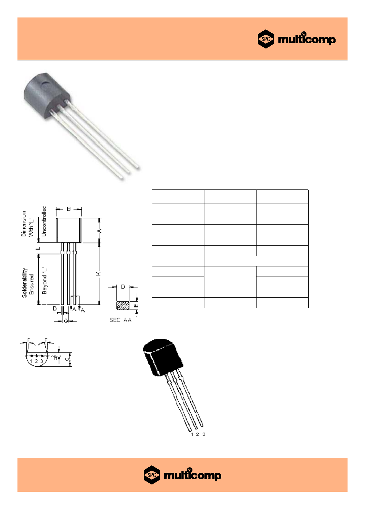
TO-92 Plastic Package
Dimensions Minimum Maximum
A 4.32 5.33
B 4.45 5.20
C 3.18 4.19
D 0.41 0.55
E 0.35 0.50
F 5°
G
1.14
1.40
H 1.53
K 12.70 -
L 1.982 2.082
Dimensions : Millimetres
Pin Configuration:
1. Emitter
2. Base
3. Collector
Page 2
2N4401
Low Power Bipolar Transistors
Page <2> 12/05/08 V1.1
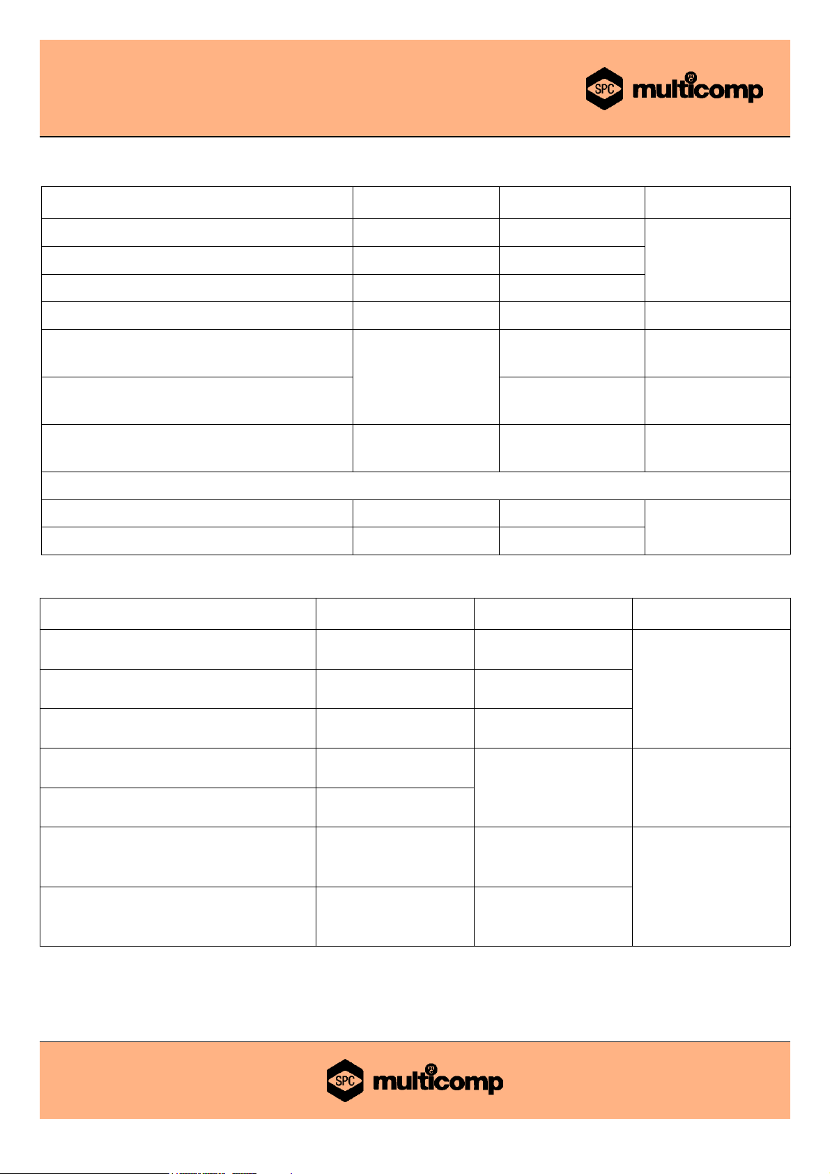
Absolute Maximum Ratings
Rating Symbol 2N4401 Unit
Collector-Emitter Voltage
V
CEO
40
VCollector-Base Voltage
V
CBO
60
Emitter-Base Voltage
V
EBO
6
Collector Current Continuous
I
C
600 mA
Power Dissipation at Ta= 25°C
Derate above 25°C
P
D
625
5.0
mW
mW/°C
Power Dissipation at Tc= 25°C
Derate above 25°C
1.5
12
W
W/°C
Operating and Storage JunctionTemperature Range
Tj, T
stg
-55 to +150 °C
Thermal Resistance
Junction to Case
R
th (j-c)
83.3
°C/W
Junction to Ambient
R
th (j-a)
200
Electrical Characteristics (Ta= 25°C unless otherwise specified)
Characteristic Symbol 2N4401 Unit
Collector Emitter Voltage
IC= 1mA, IB= 0
BV
CEO
*
>40
V
Collector Base Voltage
I
C
= 100µA, IE= 0
BV
CBO
>60
Emitter Base Voltage
IE= 100µA, IC= 0
BV
EBO
>6
Base Cut off Current
V
CE
= 35V, VEB= 0.4V
I
BEV
<0.1
µA
Collector Cut off Current
VCE= 35V, VEB= 0.4V
I
CEX
Collector Emitter Saturation Voltage
IC= 150mA, IB= 15mA
I
C
= 500mA, IB= 50mA
V
CE (Sat)
*
<0.4
<0.75
V
Base Emitter Saturation Voltage
I
C
= 150mA, IB= 15mA
I
C
= 500mA, IB= 50mA
V
BE (Sat)
*
0.75 - 0.95
<1.2
*Pulse Test : Pulse Width: ≤300µs, Duty ≤2.0%
Page 3

2N4401
Low Power Bipolar Transistors
Page <3> 12/05/08 V1.1
Electrical Characteristics (Ta= 25°C unless otherwise specified)
Characteristic Symbol 2N4401 Unit
DC Current Gain
I
C
= 0.1mA, VCE= 1V
I
C
= 1mA, VCE= 1V
I
C
= 10mA, VCE= 1V
IC= 150mA, VCE= 1V*
I
C
= 500mA, VCE= 2V*
h
FE
>20
>40
>80
100 - 300
>40
-
Dynamic Characteristics
Small Signal Current Gain
IC= 1mA, VCE= 10V, f = 1KHz
h
fe
40 - 500 -
Input Impedance
I
C
= 1mA, VCE= 10V, f = 1KHz
h
ie
1.0 - 15
kΩ
Voltage Feedback Ratio
IC= 1mA, VCE= 10V, f = 1KHz
h
re
0.1 - 8.0
x10
-4
Output Impedance
IC= 1mA, VCE= 10V, f = 1KHz
h
oe
1.0 - 30
µΩ
Collector-Base Capacitance
VCB= 5V, IE= 0, f = 100KHz
V
CB
= 10V, IE= 0, f = 140KHz
C
cb
<6.5
pF
Emitter-Base Capacitance
VEB= 0.5V, IC= 0, f = 100kHz
C
eb
<30
Transition Frequency
IC= 20mA, VCE= 10V, f = 100MHz
f
T
>250 MHz
Switching Characteristics
VCC= 30V, VEB= 2V
I
C
= 150mA, IB1= 15mA
Delay Time
t
d
<15
ns
Rise Time
t
r
<20
VCC= 30V, IC= 150mA
I
B1
= IB2= 15mA
Storage time
t
s
<225
ns
Fall Time
t
f
<30
*Pulse Test : Pulse Width: ≤300µs, Duty ≤2.0%
Page 4

2N4401
Low Power Bipolar Transistors
Page <4> 12/05/08 V1.1
DC Current Gain
h
FE
, DC Current Gain (Normalized)
ICCollector Current (mA)
DC Current Gain
V
CE
, Collector-Emitter Voltage (V)
IBBase Current (mA)
On Voltages
Voltage (V)
ICCollector Current (mA)
Page 5

2N4401
Low Power Bipolar Transistors
Page <5> 12/05/08 V1.1
DC Current Gain
h
FE
, DC Current Gain (Normalized)
ICCollector Current (mA)
Collector Saturation Region
V
CE
, Collector-Emitter Voltage (V)
IBBase Current (mA)
Page 6

2N4401
Low Power Bipolar Transistors
Page <6> 12/05/08 V1.1
ICCollector Current (mA)
Voltage (V)
On Voltages
Part Number Table
Package Part Number
TO-92 2N4401
Page 7

For enquiries from all other markets
2N4401
Low Power Bipolar Transistors
Page <7> 12/05/08 V1.1
Notes:
International Sales Offices:
AUSTRALIA – Farnell
Tel No: ++61 1300 361 005
Fax No: ++61 1300 361 225
FRANCE
– Farnell
Tel No: ++ 33 474 68 99 99
Fax No: ++ 33 474 68 99 90
NORWAY
– Farnell
Tel No: 800 146 70
Fax No: 800 146 76
AUSTRIA
– Farnell
Tel No: ++ 43 662 2180 680
Fax No: ++ 43 662 2180 670
GERMANY – Farnell
Tel No: ++ 49 89 61 39 39 39
Fax No: ++ 49 89 613 59 01
PORTUGAL – Farnell
Tel No: ++ 34 93 475 8804
Fax No: ++ 34 93 474 5288
RUSSIA – Farnell
Tel No: ++ 44 870 1200 208
Fax No: ++ 44 870 1200 209
ESTONIA
– Farnell
Tel No: ++ 358 9 560 7780
Fax No: ++ 358 9 345 5411
NETHERLANDS
– Farnell
Tel No: ++ 31 30 241 7373
Fax No: ++ 31 30 241 7333
UK – Farnell
Tel No: ++ 44 8701 200 200
Fax No: ++ 44 8701 200 201
SINGAPORE
–
Farnell-Newark
Tel No: ++ 65 6788 0200
Fax No: ++ 65 6788 0300
HONG KONG
–
Farnell-Newark
Tel No: ++ 852 2268 9888
Fax No: ++ 852 2268 9899
HUNGARY
- Farnell
Tel No: ++ 44 870 1200 208
Fax No: ++ 44 870 1200 209
BELGIUM – Farnell
Tel No: ++ 32 3 475 2810
Fax No: ++ 32 3 227 3648
BRAZIL
– Farnell-Newark
Tel No: ++ 55 11 4066 9400
Fax No: ++ 55 11 4066 9410
IRELAND – Farnell
Tel No: ++ 353 1 830 9277
Fax No: ++ 353 1 830 9016
INDIA
- Farnell
Tel No: ++ 44 870 1200 208
Fax No: ++ 44 870 1200 209
ISRAEL – Farnell
Tel No: ++ 180 937 0015
Fax No: ++ 180 937 0014
SPAIN
– Farnell
Tel No: 901 20 20 80
Fax No: 901 20 20 90
CHINA
– Farnell-Newark
Tel No: ++86 10 6238 5152
Fax No: ++86 10 6238 5022
CZECH REPUBLIC
- Farnell
Tel No: ++ 44 870 1200 208
Fax No: ++ 44 870 1200 209
ITALY – Farnell
Tel No: ++ 39 02 93 995 200
Fax No: ++ 39 02 93 995 300
SWEDEN – Farnell
Tel No: ++ 46 8 730 50 00
Fax No: ++ 46 8 83 52 62
MALAYSIA
–
Farnell-Newark
Tel No: ++ 60 3 7873 8000
Fax No: ++ 60 3 7873 7000
SWITZERLAND
– Farnell
Tel No: ++ 44 204 64 64
Fax No: ++ 44 204 64 54
DENMARK – Farnell
Tel No: ++ 45 44 53 66 44
Fax No: ++ 45 44 53 66 06
UK – CPC
++ 44 8701 202 530
++ 44 8701 202 531
USA –
Newark
Tel No: 800 463 9275
NEW ZEALAND
– Farnell
Tel No: 0800 90 80 80
Fax No: 0800 90 80 81
EXPORT
– Farnell
Tel No: ++ 44 8701 200 208
Fax No: ++ 44 8701 200 209
export
FINLAND – Farnell
Tel No: ++ 358 9 560 7780
Fax No: ++ 358 9 345 5411
Disclaimer This data sheet and its contents (the "Information") belong to the Premier Farnell Group (the "Group") or are licensed to it. No licence is granted for the use of it other than for information purposes
in connection with the products to which it relates. No licence of any intellectual property rights is granted. The Information is subject to change without notice and replaces all data sheets previously supplied.
The Information supplied is believed to be accurate but the Group assumes no responsibility for its accuracy or completeness, any error in or omission from it or for any use made of it. Users of this data
sheet should check for themselves the Information and the suitability of the products for their purpose and not make any assumptions based on information included or omitted. Liability for loss or damage
resulting from any reliance on the Information or use of it (including liability resulting from negligence or where the Group was aware of the possibility of such loss or damage arising) is excluded.
This will not operate to limit or restrict the Group's liability for death or personal injury resulting from its negligence. SPC Multicomp is the registered trademark of the Group. © Premier Farnell plc 2008.
http://www.farnell.com
http://www.newark.com
http://www.cpc.co.uk
 Loading...