

Page 1
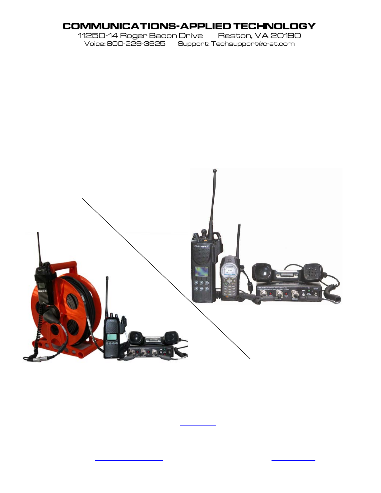
Setup and Operati ng Procedures
ICRI/2P™
Incident Commanders’ R a dio I nterface™
A Rapidly Deployable, Radio Interoperability Solution for Public Safety Personnel
Revision I
3/2009
COMMUNICATIONS-APPLIED TECHNOLOGY CO., INC.
C-AT TECHNICAL SUPPORT at 800-229-3925 x23 (voice) 703-471-4428 (fax), or
MANUFACTURED BY
RESTON, VA., USA
CAGE CODE: 0EEY2
www.c-at.com
http://
If you have any questions, please contact:
Page 2

TABLE OF CONTENTS:
THEORY OF OPERATION ........................................................................................................3
PRE-OPERATIONAL ACTIVITIES ..........................................................................................4
INTEROPERABILITY DOS AND DON’TS ..............................................................................5
1.0 SET-UP AND USE INSTRUCTIONS ...............................................................................6
2.0 CONTROLS AND INDICATORS ....................................................................................7
FRONT PANEL ............................................................................................................................... 7
REAR PANEL ................................................................................................................................. 8
3.0 ICRI POWER ......................................................................................................................9
POWER THE ICRI WITH INTERNAL 9V BATTERY: ........................................................................... 9
POWER THE ICRI WITH THE OPTIONAL C-AT BATTERY PACK (8 “AA” CELLS) ........................... 10
POWER THE ICRI-2P WITH CIGARETTE LIGHTER OR ALLIGATOR CLIPS CABLE (P/N 179.0730).... 11
4.0 PORTABLE RADIO INTERFACE ................................................................................12
CONNECTING THE PORTABLE RADIO............................................................................................ 12
OPERATING THE PORTABLE RADIO AFTER CABLE CONNECTION ................................................... 14
USING A NEXTEL™
SETTING THE RADIO TO BRIDGE THROUGH THE ICRI ................................................................... 15
TROUBLESHOOTING RADIO SETUP ............................................................................................... 15
PHONE IN DIRECTCONNECT™ MODE ........................................................... 14
5.0 ICRI “P-O-T-S” PHONE LINK ......................................................................................16
CONNECTING A LAND LINE TELEPHONE TO THE ICRI-2P ............................................................. 16
CONNECTING A CELLULAR TELEPHONE TO THE ICRI-2P ............................................................. 17
6.0 THE LOCAL HANDSET .................................................................................................18
USING THE HANDSET ................................................................................................................... 18
ADJUSTING THE VOLUME ............................................................................................................ 18
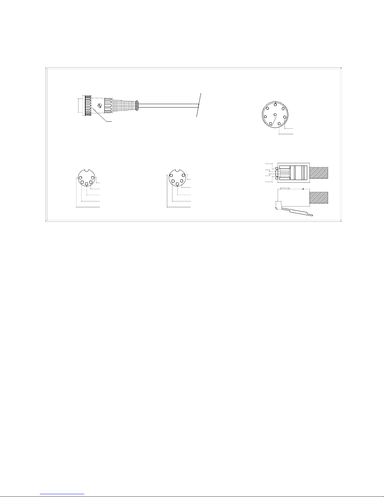
APPENDIX A: CONNECTOR PIN-OUT DATA .....................................................................19
APPENDIX B: ICRI BOARD ADJUSTMENTS ......................................................................20
APPENDIX C: ICRI OPTIONS .................................................................................................22
CONNECTING EXTERNAL SPEAKERS ........................................................................................... 22
ICRI UNIT IDENTIFIER ................................................................................................................ 22
250’ RADIO EXTENSION INTERFACE (CABLE REEL) P/N 179.6213 ............................................. 23
SET-UP OF THE CABLE-REEL ........................................................................................................ 24
APPENDIX D: PART NUMBERS FOR ICRI, ACCESSORIES AND RADIO CABLES..27
ICRI CONFIGURATIONS .............................................................................................................. 27
ICRI OPTIONS ............................................................................................................................. 28
INTERFACE CABLES FOR STANDARD DIN CONNECTOR ICRI ...................................................... 30
APPENDIX E: FCC 15.21 INFORMATION TO USER: ........................................................34
Page 3

THEORY OF OPERATION
The “2P” can provide a communications bridge, or link, between two public s afety agencies with
otherwise incompatible radios; can quickly establish the link as a tactical situation rapidly unfolds;
and requires minimal resources to enable it initially, or to maintain its operation over many hours.
The 2P will provide full operational capabilities moments after arrival on-scene, and remain
operational for 30+ hours powered by 8 “AA” batteries, or 6 hours powered only by an internal 9V
alkaline battery.
The 2P performs two primary functions for public safety personnel:
• Distributes the audio received from one two-way radio, handset/headset, or telephone, to other
devices connected to the 2P.
• Utilizes this same incoming audio to “key” the other radios or telephones connected to the
ICRI. The radios can be portables, mobile, NEXTEL “Direct Connect” phones, or a
combination. Landline telephones, cell phones, STU, STE or sat ellite phones can also be
connected to the ICRI.
The ICRI-2P circuitry does not attempt to modify or digitally process the incoming audio, so that
unnecessary delays are not inserted into the audio transfer or “keying” processes. Radios, telephones,
and/or recording devices connected to the I CRI ar e provided with the incoming a udio, essentially in
real-time. An audio “buffer” preserves the first syllables of incoming audio processed through
“trunking” radio systems.
This version of the ICRI contains two circuits that key the radios connected to the ICRI; these circuits
are commonly referred to as “VOX” or “voice-activated switches.” Only the VOX directly connected
to the incoming audio is used to key each of the other radios simulta neous ly ( all o thers are temporarily
disabled, to prevent a second “voice” from causing a disruption of communication).The ICRI uses
these circuits to perform other controlling functions as well.
- 3 -
Page 4

PRE-OPERATIONAL ACTIVITIES
Some pre-planning is necessary to ready the ICRI for rapid deployment. The following should be
accounted for before placing the ICRI on-line:
1. Determine what the power source will be for the ICRI. Verify that a “fresh,” 9V, al kaline
battery is available or that one of the external power source option are available.
2. Determine what brand and model of radios will be connected to the ICRI and that an
“interface” cable for each radio is available.
3. If radios are not maintained with the I CRI, advise participating agencies that they will need to
supply a “spare” radio, for the radio interoperability.
4. Verify that the radios are known to operate prope rly and have at least one fully charged battery
or other reliable power source.
The “2P” can be powered by an internal 9-volt battery or an external DC source up to 20 VDC.
Among the power sources that can be used to power the ICRI are:
12 volt vehicle battery
Vehicle cigarette lighter
115v AC (with an external adapter)
BA590 “military”
Commercial dry-cell or other battery (7.2V or greater)
C-AT 12 volt battery pack (uses 8 “AA” batteries)
Single, 9V alkaline battery
The ICRI’s internal reg ulated power supply is reverse polarity protected, but it is important to check
polarity of DC supplies before connecting them to the ICRI.
- 4 -
Page 5

INTEROPERABILITY DOS AND DON’TS
These “universal” rules will help to ensure that the part of communications interopera bility will w ork
properly.
1. Maintain COMSEC when forming interoperability bridges.
2. Verify that only one interopera bility bridg e in the area is using the radio fre quencies that y ou
will be using.
3. Audio and RF cables should be separated from AC power cables by 12” (use an external DC
source or batteries when you cannot maintain the separation).
4. When plugging in two or more radios within the same radio band (i.e. VHF) into a radio
bridge, like the ICRI, provide as much vertical separation as possible to reduce the chance for
interference due to the transmitted signal from one radio re ducing the rece ive se nsitivi ty of the
other “in band” radios. Consider using external mobile antennas connected to the radios if
necessary. Use only bridge interconnect cables that are well shielded.
5. Some bridge cables contain in-line, audio amplifiers for radios designed with low audio levels.
It is best to rout those cables away from radio antenna s and conne ctors ---lots of RF and distort
the audio amplifier’s output to the bridge.
6. Don’t use “SCAN” mode for any radios connected to a radio bridge. This is particularly
important when you are using the bridge as a tactical repeater, where two or more radios have
similar channel programming. If both radios are capable of hearing the same signal, they will
key each other up "ping-pong,” interfering with the function of the bridge.
7. When using a remote device to control an interoperability bridg e, verify conf iguration of talk
groups with on-scene commander. Do not change talk g roups setting s without conf irmation
from local personnel to avoid inadvertently r emoving necessary personnel from r adio traffic.
- 5 -
Page 6
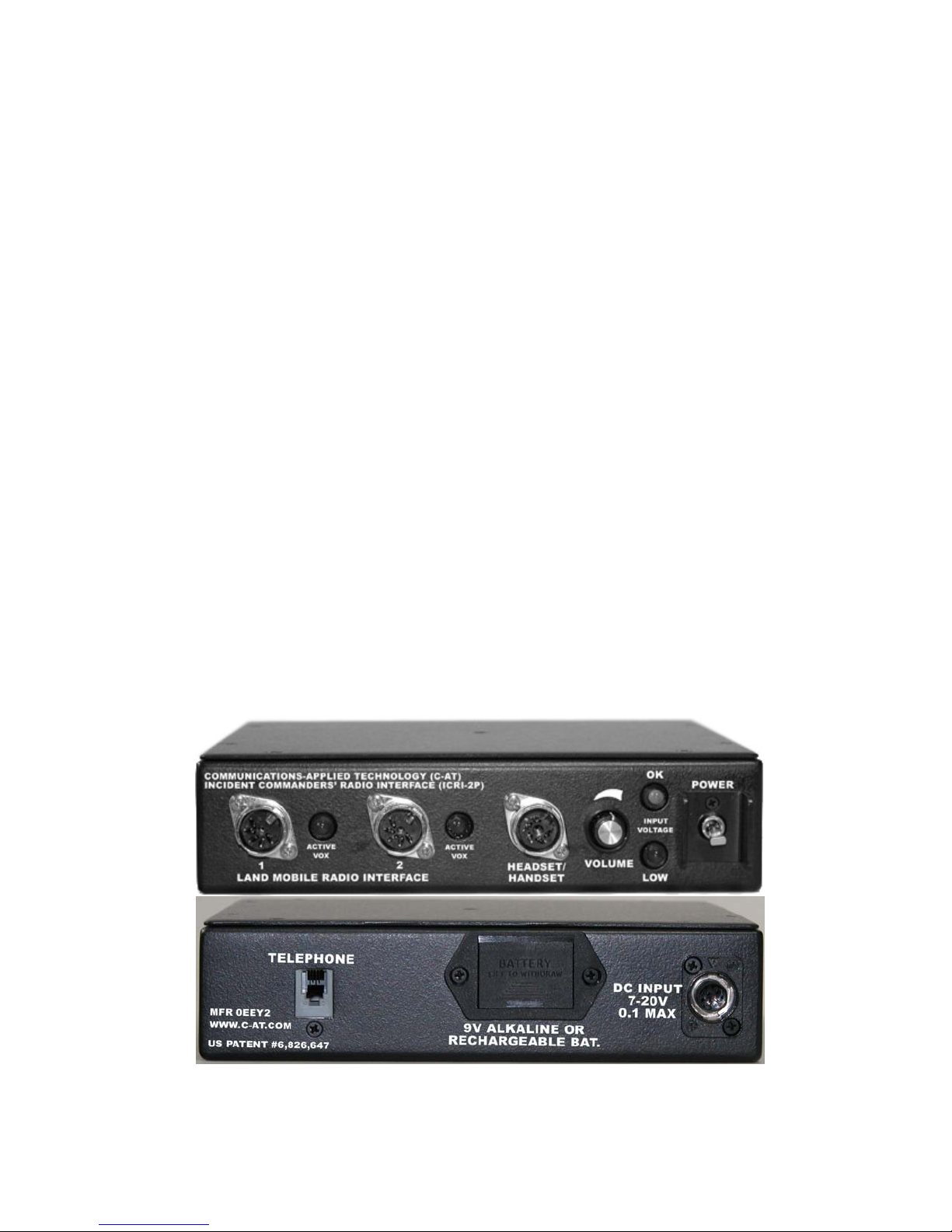
1.0 Set-up and Use Instructions
As a minimum, the following will be required for ICRI operation:
• ICRI assembly
• A 9V alkaline battery or power supply with interconnect cable to ICRI
• Two radio interface cables or a rad io in terface cab le an d a cell phone cable (no ext ernal
cable needed for land-line phone connection)
• Two radios and/or a phone
Determine power method and connect to ICRI. Insert 9V battery into housing on rear of I CRI -2P if
needed.
Place the POWER switch in the “ON” position; the “OK” LED should be lit. This will provide at
least 6 hours of continuous use.
Check the radios’ transmit and receive functions, battery and channel selection.
Connect one interface cable to the ICRI and one radio
Connect the handset.
Set the volume controls for the radios and handset to a position. Mid way between fully
CLOCKWISE and fully COUNTER-CLOCKWISE
NOTE: A radio’s internal speaker will be disabled when the interconnect cable has been attached,
so you must use the handse t, or a second radio on the same channel to verify the communications
link.
Active VOX will light when the radio is transmitting.
Repeat with the other radio/phone to be used.
FIGURE 1: ICRI/2P FRONT AND REAR PANEL
- 6 -
Page 7
2.0 Controls and Indicators
Front Panel
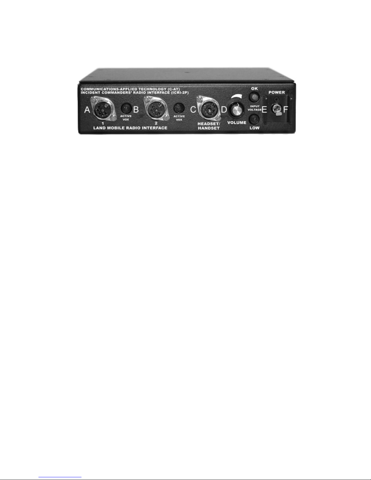
FIGURE 2: FRONT PANEL
RADIO INTERFACE JACKS (1 and 2) A
The two radio interface jacks on this unit are a 5-pin 180° locking-DIN ty pe jack. Make sure the interface
cable is fully seated before use. The radio’s internal speaker and hand mic functions are disabled. Use the
ICRI hand set t o talk/listen if using the ICRI as a base station (a remote speaker jack is an ICRI option ).
Pinout:
1- Ground
2- Audio from radio
3- Audio to radio
4- No connection
5- P-T-T Enable
VOICE ACTIVATED CIRCUIT (VOX) LED INDICATOR: B
When lit (only one at a time) indicates the VOX, of the “inputting” radio, is active. If the VOX stays
permanently lit, you may need to turn down the volume of the radios until the light is lit only during input.
HANDSET INTERFACE JACK C
This five pin, 24 0° connecto r suppo rts the ha ndse t (p/ n 280.0125 only; other ICRI handset models are not
compatible).
Pinout:
1- Ground
2- Audio from handset’s microphone to the ICRI/radios
3- PTT
4- Audio to the handset’s speaker from the ICRI/radios (+)
5- Audio to the handset’s speaker from the ICRI/radios (-)
HANDSET VOLUME CONTROL D
This knob co ntrols the vol ume to the handse t only . Turn clockwise for more volume and counterclo ckwi se
for less volume.
To adjust the volume of the radios, use the corresponding radio’s volume knob.
POWER STATUS INDICATOR LIGHT: E
When lit the ICRI-2P is powered up. The low voltage light will light when the voltage is below 7.5V. If
using internal battery power, there will be approximately 6 hours of operation before the battery will need to
be replaced.
POWER SWITCH: F
This two-position switch is used to turn the ICRI “ON” and “OFF.” Th ere is no microprocessor “boot”
time. If the unit is turned off, it will immediately resume the bridge link when turned back on.
- 7 -
Page 8
Rear Panel
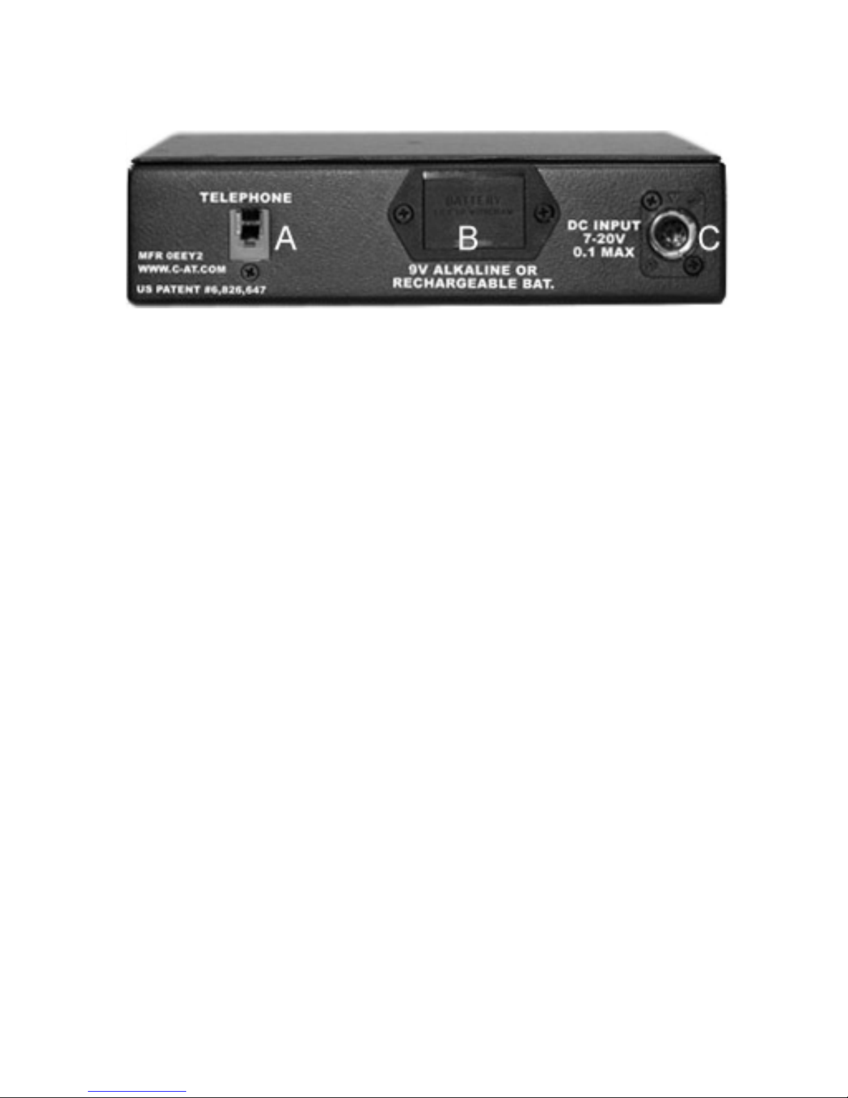
FIGURE 3: REAR PANEL
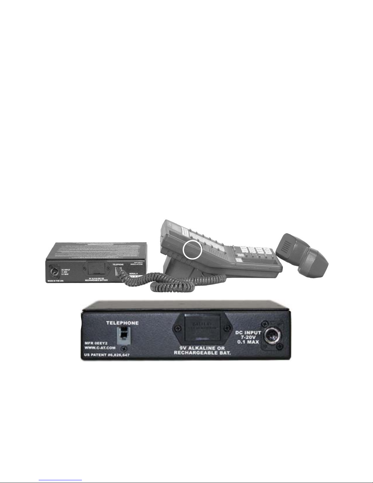
RJ22 TELEPHONE JACK: A
This RJ22 (4 wires) jack supports the connection of the ICRI to a land-line tele phone through the
telephone’s handset wiring (using the coiled cord between the telephone’s base with touchpad and
the handset) or the 2.5mm jack on a cell phone (using C-AT interconnect cable P/N 179.0693).
A phone connected to the ICRI will be used for dialing and other keypad functions since the
speaker and mic functions are disabled. Use the ICRI’s handset to talk/listen to the remote
individual, if using the ICRI as a base station.
INTERNAL 9V BATTERY: B
Housing holds a single, 9V, alkaline battery. A “fresh” battery will provide approximately 6 hours
of run time during full operation
DC INPUT JACK: C
This is a 2-pin locking-type jack is the input. Use the C-AT supplied power supply or contact C-
AT for additional power options. An eight “AA” battery pack is available for 30 hours of run
time, as well as AC or DC power option.
Pinout:
1 - +7 to +20 VDC
2 - Ground
Note: See appendix C for pinout.
- 8 -
Page 9
3.0 ICRI Power
Select the power source to be used
Single, 9V alkaline battery
C-AT 12 volt battery pack (uses batteries)
12 volt vehicle battery
Vehicle cigarette lighter
115v AC (with an external adapter)
BA590 “military”
Commercial dry-cell or other battery (7.2V or greater)
Power the ICRI with internal 9V battery:
A single 9V alkaline battery will power the ICRI for at least 6 hours of continuous use.
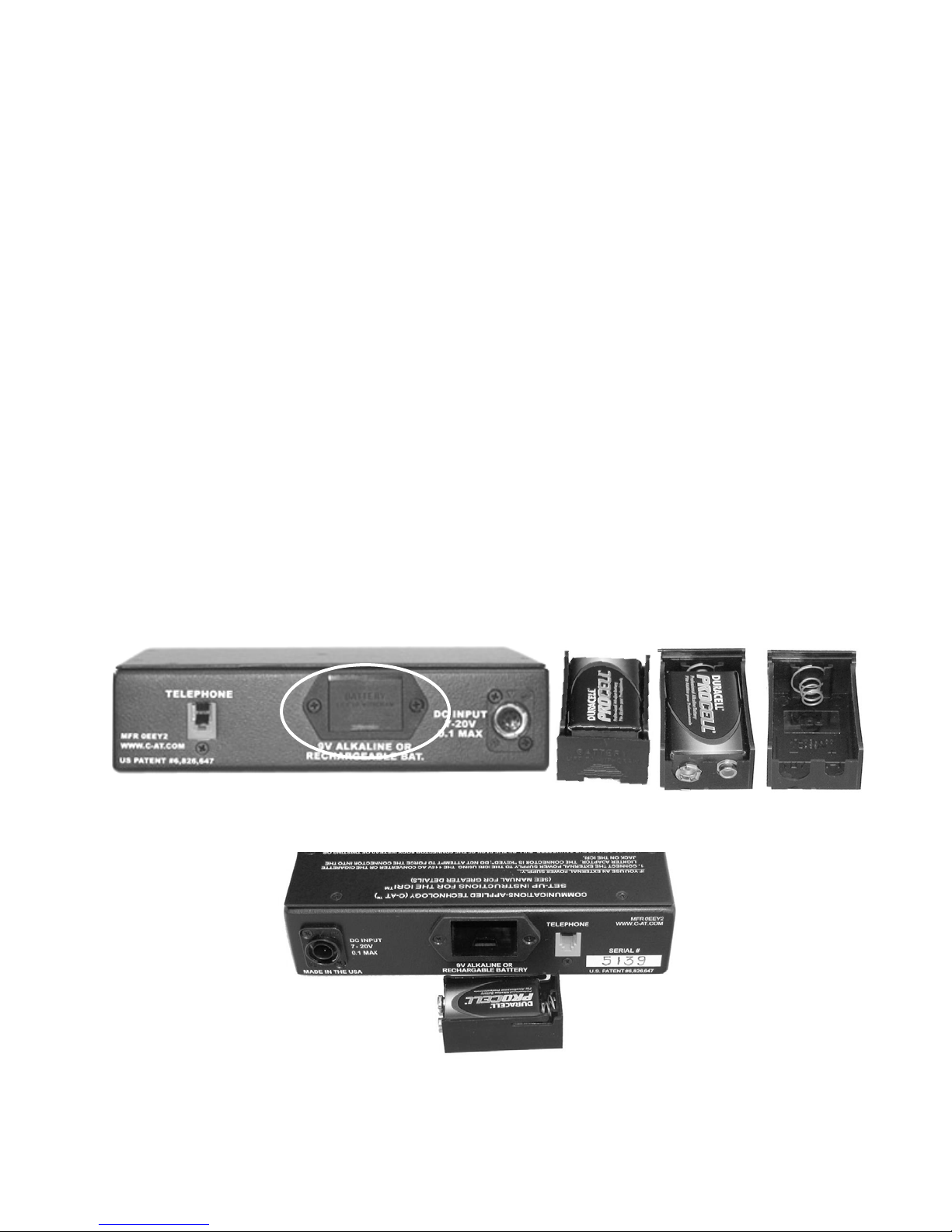
To install the 9V ba ttery , re move the battery housing from the rear of the ICRI by pushing up on the
compartment “door” and then pulling it out.
Place the 9V battery in the housing as indicated in Figure 5.
Reinsert the battery housing into the ICRI. Be sure that the battery housing is firmly seated in the
ICRI.
NOTE: The word “Battery” on the end of the holder m ust be right side up before attempting to
install the battery holder.
FIGURE 4: INTERNAL 9V BATTERY HOLDER
INSTALLED
FIGURE 5: 9V ALKALINE BATTERY
AND HOLDER
FIGURE 6: 9V HOLDER WITH BATTERY READY TO BE I N S TALLED
IN ICRI-2P REAR COMPARTMENT
- 9 -
Page 10
Power the ICRI with the optional C-AT battery pack (8 “AA” cells)
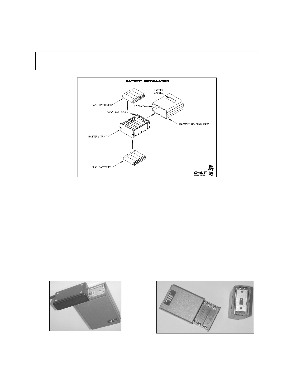
The battery housing is comprised of two parts: the exterior case and an internal tray.
NO TOOLS ARE NEEDED TO REMOVE THE TRAY AND REPLACE THE BATTERIES.
FIGURE 7: BATTERY INSTALLATION (DRAWING)
Hold the battery hous ing securely in the palm of the hand with metal batter y te rminal plate f acing up.
Push firmly on the center of the battery terminal plate, until the battery tray is released.
Remove old batteries and discard properly.
Replace the eight "AA” alkaline batteries, observing polarity markings within the tray.
Note: There is a “key” tab on the side of the tray and a “keyway” inside of case.
To reinsert the tray, make sure the tray’s key goes in the matching slot side of the case. Insert the tray
into the housing from the bottom end of the case, pushing the tray until it “locks” into place
To reinstall the assembled battery pac k onto the adapter, align the slots on the top of the battery pack
with the slide rails on the ada pter. Slide the ba ttery pack onto the adaptor until it “locks” in place and
the edges of the battery pack are aligned with the edges of the adaptor. (Figure 8)
FIGURE 8: BATTERY CASE
FIGURE 9: BATTERY CASE (INTERIOR)
- 10 -
Page 11
Power the ICRI-2P with cigarette lighter or alligator clips cable (P/N 179.0730)
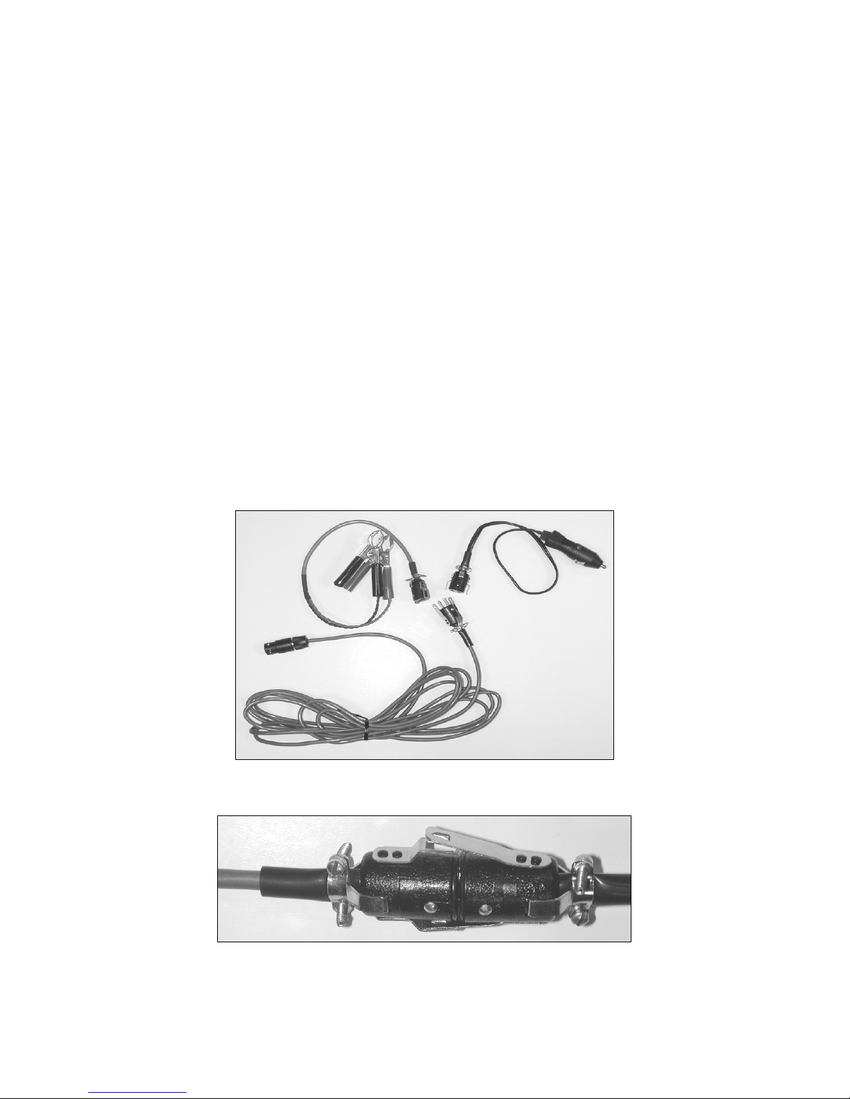
NOTE: The cable assembly consists of three subassemblies: (a) the universal interconnect cable,
(b) the cigarette lighter plug with locking in-line jack and (c) the alligator clips with locking inline jack.
After selecting the DC source, conn ect the in-line jack to the in-line plug. Note that the pins are
polarized and the connection is made so that the jack’s locking “blades” slide between the “blades”
on the plug and the body of the plug.
Connect the assembled cable to the DC source.
Connect the other end of the assembled cable to the ICRI’s rear panel jack labeled DC INPUT.
Note: Care should be taken to align the arrow on the plug with the arrow on the jack before
attempting to insert the plug.
To remove the plug, hold the fluted part of the plug’s barrel and pull straight out.
To separate the in-line socket, gently lift one of the blades from the plug so that the locking
mechanism is released. Then pull the plug and socket apart.
FIGURE 10: DC POWER SUPPLY SUB-ASSEMBLIES
FIGURE 11: IN-LINE PLUG ASSEMBLY
- 11 -
Page 12
4.0 Portable Radio Interface
NOTE: Radio interconnect cables are generally specific to a radio brand and m odel, although
some manu facturer’s use the same conn ector for several radio models. Interco nnect cables
provided by C-AT have a seven-digit part n umber label on the cable. A chart, crossing these
numbers with the radio brands/models appear in Appendix A of this manual. Contact C-AT for
set-up instructions for your specific mobile radios.
Connecting the portable radio
Connect the radio specific end of the ICRI interconnect cable onto the radio, as y ou would install a
speaker/microphone.
If present, tighten connector's locking screws (optional); it is important that th e connector be f irmly
seated against the electrical terminals on the body of the radio, so t hat good electrical contact is
made.
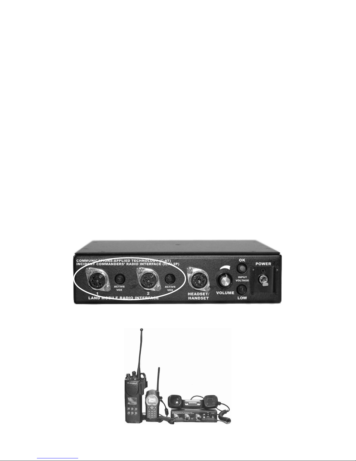
Connect the other end of the interconnect cable to RADIO INTERFACE jacks labeled “1” or “2.”
NOTE: The plug on the interconnect cable and the jack on the ICRI ar e “keyed.” Be sur e to
align the key before inserting the plug on to the connector or the connection may be damaged.
After the plug is fully seated on the jack, the locking ring on the plug should be turned clockwise
until the ring cannot be turned further---about 1/8th turn.
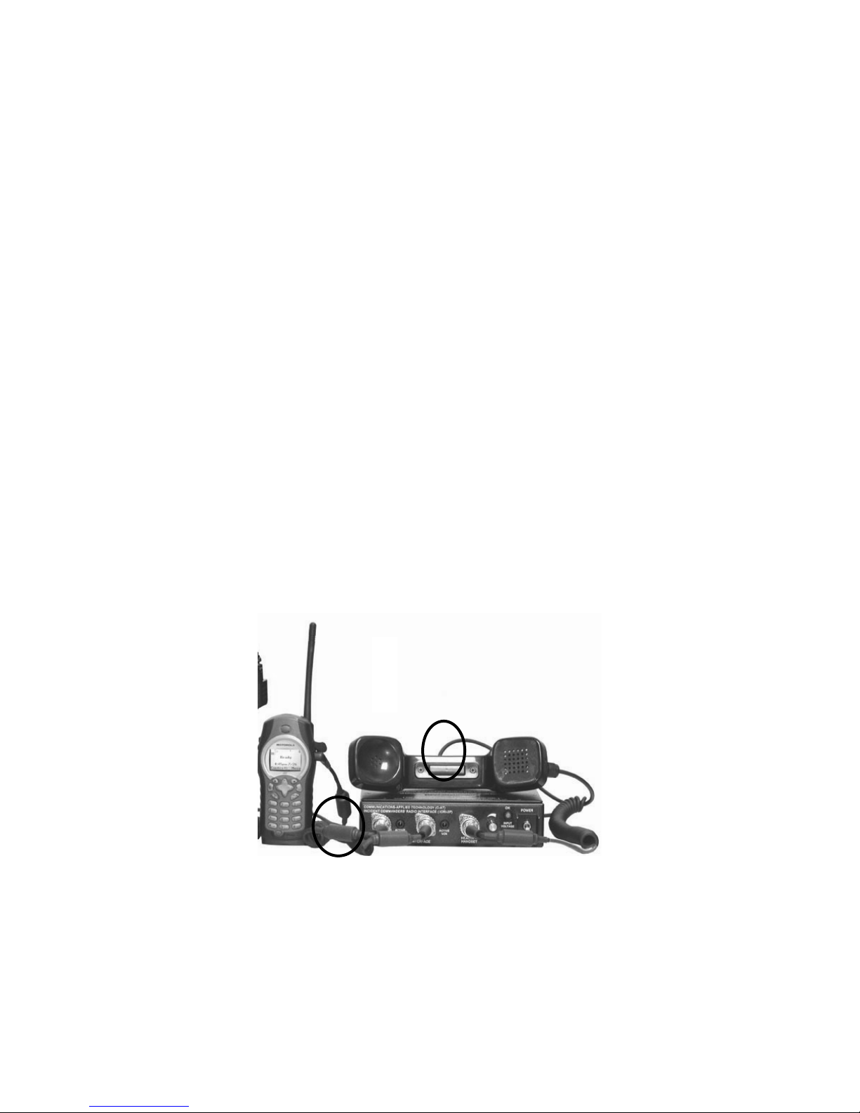
FIGURE 13: TWO RADIOS CONNECTED TO ICRI/2P
FIGURE 12: ICRI-2P INTERFACE JACKS
- 12 -
Page 13
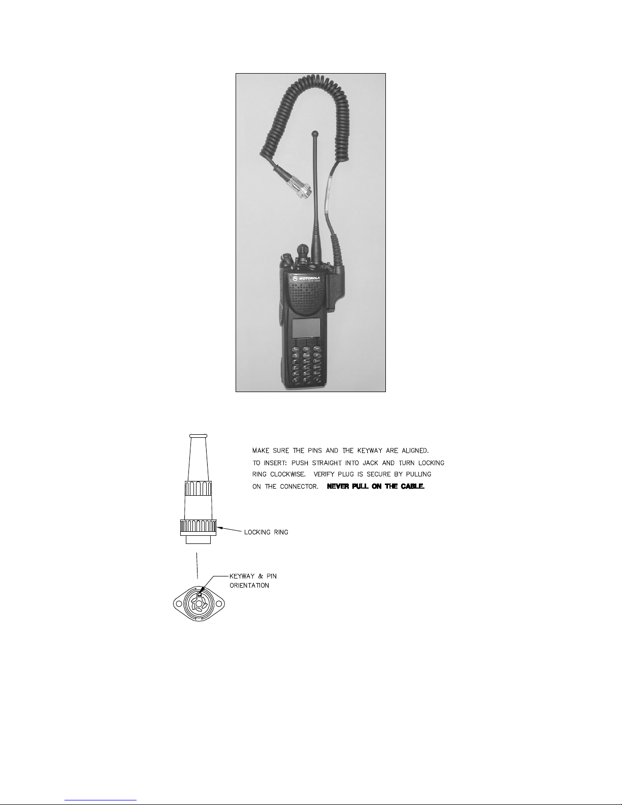
FIGURE 14: RADIO WITH IC RI CABLE ATTATCHED
FIGURE 15: JACK ASSEMBLY (DRAWING)
To disconnect the connector for cable storage, push inward on the locking ring with minimal for ce,
and at the same time turn the ring counter-clockwise 1/8 turn to release the locki ng mechanism.
Then, holding the metal barrel of the connector, pull the connector straight out of the jack.
- 13 -
Page 14
Operating the portable radio after cable connection
After a radio is connected to the ICRI, the ra dio’s internal speaker and micr ophone is disabled. The
user will be unable to hear any audio or speak from the connected radio.
To verify the radio is transmitting and receiving properly, use the local handset (See Section 6.
Using the Local Handset)
Using a Nextel™ phone in DirectConnect™ mode
When connecting a Nextel handset, the connection is made through the handset's "headset" jack .
This connection is the 2.5mm jack on the Nextel Falcon (i530) series phones/handsets.
NOTE: At this point, the speaker and mic of the Nextel have been disabled; you will be able to
communicate through the ICRI handset.
Connect the other end of the interconnect cable to either LAND MOBILE RADIO INTERFACE
jack on the ICRI.
Set the Nextel into DirectConnect mode and program the desired Nextel “talkgroup” or
DirectConnect number.
Program the phone to stay in DirectConnect mode (See Nextel manual for directions).
NOTE: A Nextel i90 series phone should not be connected to an ICRI for DirectConnect
operation. Software in the i90 is not compatible with radio interoperability.
Audio received from the other connected radios or the ICRI ha ndset will be heard by Nextel phone
users via the Nextel network.
FIGURE 16: CONNECT TO N EXTEL™ DIRECT CONNECT™
- 14 -
Page 15

Setting the radio to bridge through the ICRI
Set the volume control on each connected radios to mid position between fully CLOCKWISE and
COUNTER-CLOCKWISE.
Set each radio to the desired channel. (They IAN not be on the same channel/frequency)
Because the ICRI is connected to the radio via the spea ker jack, the audio path on the attached radio
is disrupted. You will be unable to hear or speak through that radio. I f you can hear or talk through
the radio, the cable may not be properly attached to your radio.
The LED directly beside the interface jack will light a s audio is tr ansmitted f rom the r adio thr ough
the ICRI.
Troubleshooting radio setup
NOTE: See Interoperability DO’s and DONT’S in Appendix E.
1. Verify the radio can function normally with a speaker-mic attached.
2. Verify the radio has a charged battery.
3. Verify to the interconnect cable is firmly connected to the radio and the ICRI.
The ICRI use locking ring to secure the connector, use the radio connector locking mechanism if
provided
- 15 -
Page 16
5.0 ICRI “P-O-T-S” Phone Link
(POTS=Plain Old Telephone System)
The ICRI-2P is equipped with an RJ-22 jack located on the rear of the unit. This jack will provide
the user the ability connect a standard telephone handset, cellular telephone, military STU/STE
telephone to the ICRI and quickly establish a “patch” with radios also connect to the ICRI.
NOTE: Contact C-AT if you need a connection for a Nokia TM or other cell phone wi thout a
Tip/Ring, 2.5mm handset jack.
Connecting a land line telephone to the ICRI-2P
NOTE: Do not remove the telephone’s handset from its cradle
Disconnect the coiled cable from the telephone’s handset; do not disconnect the cable from the base
of the telephone.
Plug the cable directly into the jack on the rear of the I CRI -2P; the jack is labeled “TELEPHONE”
NOTE: The plug and jack are “keyed” and must be aligned.
FIGURE 17: ICRI-2P CONNECTED TO PHONE CORD
FIGURE 18: TELEPHONE INTERFACE JACK
Remove the telephone handset from the telephone base, a dial tone should be hea rd in the earp hones
of the portable radio and in the earpiece of the "local" handset.
Dial the telephone number of another telephone.
To receive an incoming call, the handset must be on the telephone base and an individual must be
available to take the phone “off hook.”
- 16 -
Page 17
Connecting a cellular telephone to the ICRI-2P
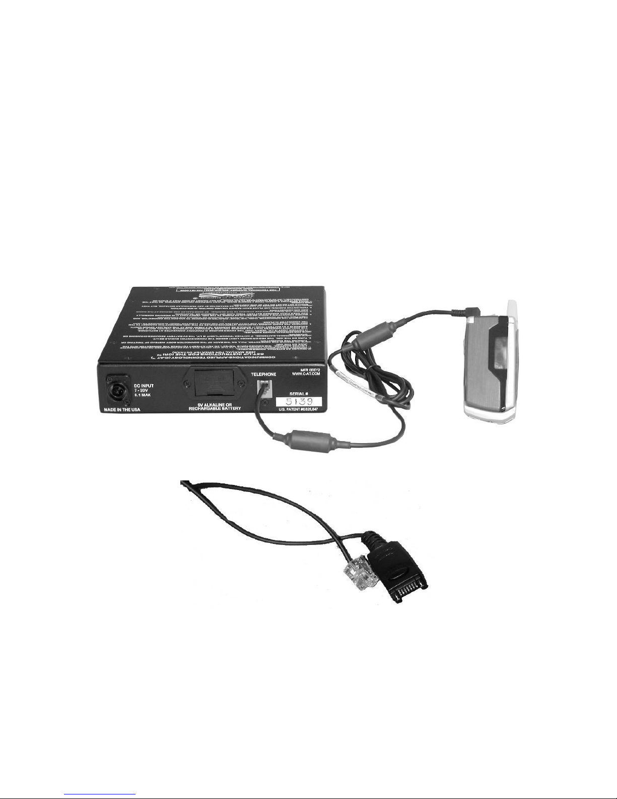
When connecting to a cellular telephone using the interface cable, P/N 179.0693, insert the 2.5mm
(1/16”) plug into the headset jack on the cellular telephone. Be sure it is fully pushed into the
telephone jack; See FIGURE 19.
Set cell phone’s speaker/earphone audio to a mid-level setting following the cell phone
manufacturer's instructions.
The call phone should be in the "auto answer" mode. See phone's instruction manual for the
procedure.
Dial a remote telephone or wait for an incoming call from another telephone.
To receive an incoming call, the phone must be set to auto answer, or an individual must be available
to answer the phone by pressing SEND or equivalent.
FIGURE 19: ICRI-2P CONNECTED TO CELL PHONE
FIGURE 20: RJ-10 CABLE FOR NOKIA™
- 17 -
Page 18
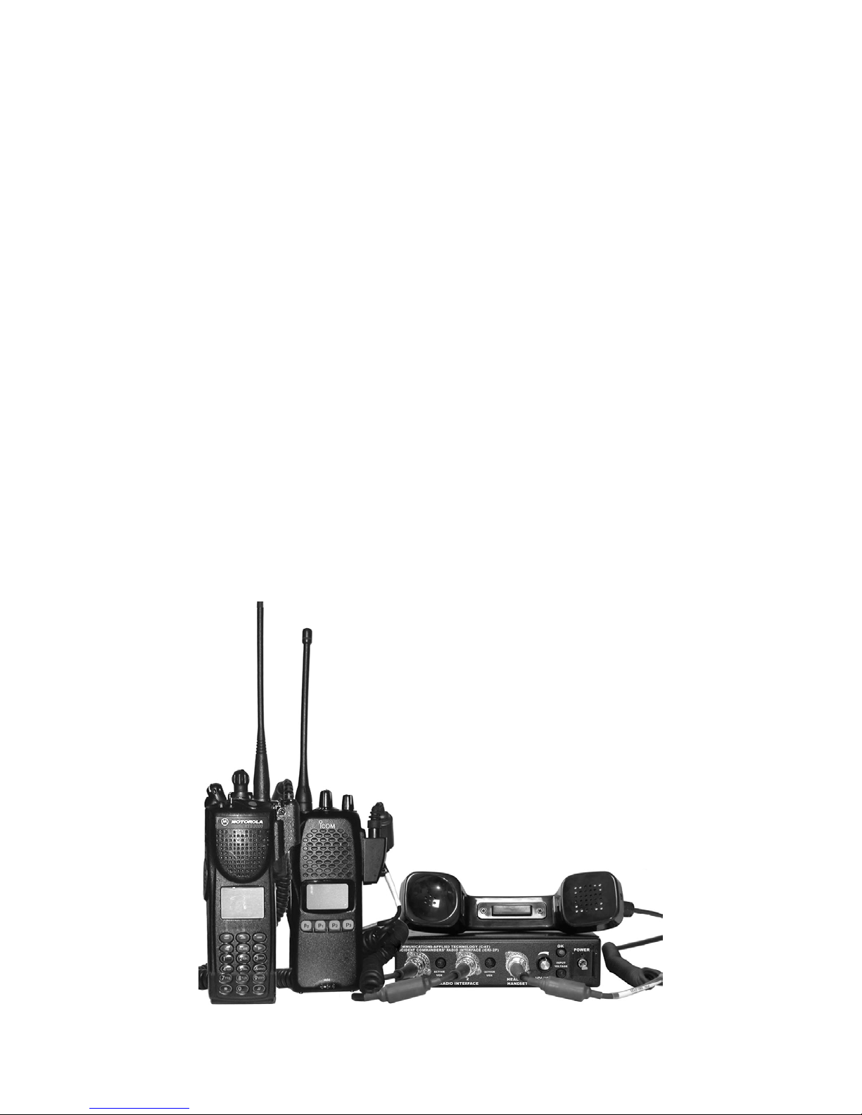
6.0 The Local Handset
The handset provides the user with a local interface to the ICRI , without using a radio. It w ill allow
an individual to hear and respond to all audio transmitted through the ICRI from the radios and
telephone connected to the ICRI.
Using the handset
Connect the handset to the jack labeled “Handset.”
Make sure to properly align the pins of the plug before inserting into the jack.
After the plug is fully seated on the jack, the locking ring on the plug should be turned clockwise
until the ring cannot be turned further.
Adjusting the volume
The audio level to the handset speaker can be adjusted by the rotating the volume knob above the
jack. Counterclockwise decreases the audio level, and clockwise increases the listening level.
Set the audio level to mid position.
The handset microphone is enabled when the push-to-talk bar in the center of the handset is
depressed and held down.
FIGURE 21: LOCAL HANDSET CONNECTED TO ICRI
- 18 -
Page 19
5
3
4
8
2
1
6
7
FROM THIS POINT (WIRED SIDE).
TO ICRI
ALL CONNECTOR INFORMATION VIEWED
RJ22 CONNECTOR
3- GROUND
2- AUDIO TO ICRI
1- GROUND
4- AUDI O FROM ICRI
NEUTRIX #FI8 -QTY 1
2-GND(-)
1-POWER(+)
NEUTRIX #BS1 -QTY 2
3-8 - N/C
NEUTRIX #SC8 -QTY 1
NEUTRIX #SR8 -QTY 1
POWER CONNECTOR
SWITCHCRAFT # 05CL5M
RADIO INTERFACE
4
2
1
1- GND
5-P-T-T
5
3
180°
2-AUDIO FROM RADIO
4- SABER P-T-T ONLY
4
2
3
5
1
240°
3-PTT
2- ELECTRET MIC
4-AUDIO HI+
1- GND
SWITCHCRAFT # 12CL5M
HANDSET INTERFACE
3-AUDIO TO RADIO 5-AUDIO HI-
APPENDIX A: CONNECTOR 2 P PIN-OUT DATA
FIGURE 22: ICRI 2 P PIN OUT DATA
- 19 -
Page 20
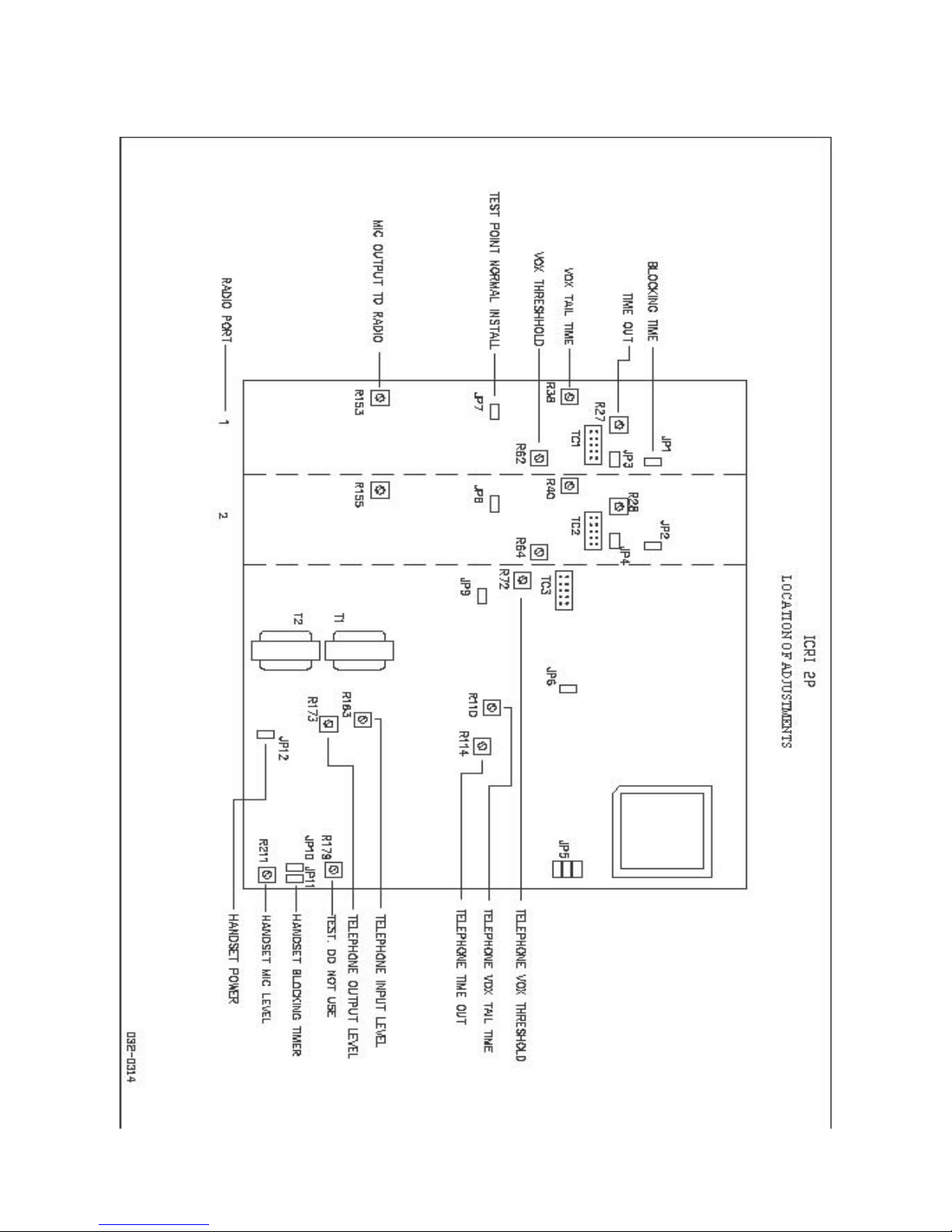
APPENDIX C: ICRI BOARD ADJUSTMENTS
- 20 -
Page 21
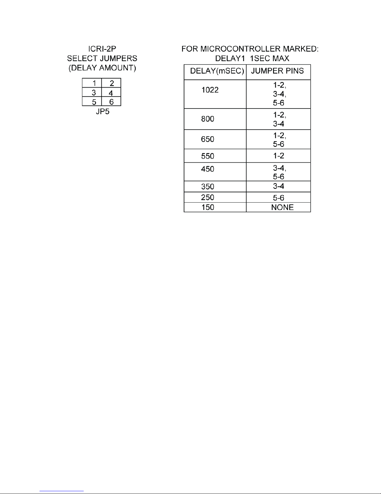
NOTES FOR ICRI-2P CONFIGURATION DRAWING:
INPUT BLOCKING TIME JUMPERS:
With jumpers "on,” the ICRI will respond to a new voice signal approximately 0.8 seconds after
the last transmission has ended. This is the standard configuration. With the jumper removed,
this time is extended to approximately 2 seconds. During this time, no new PTT can be initiated
by any input except the handset. JP1: PORT 1, JP2: PORT 2.
TIME OUT TIMER DEFEAT:
With this jumper "off,” the telephone or radio input channel will be temporarily disabled after a
timed period of continuous activity. The timing range is approximately 30 seconds to 2 minutes,
as set by time out timer adjust controls. If the input signal is removed for approximately 5
seconds, the time out timer resets and operation returns to normal. Installation of defeat jumper
turns off the time out timer and the channel will never be disabled.
HANDSET CIRCUIT POWER CONTROL:
If the handset circuit will not be used, JP12 can be removed to turn off power to the circuit and
extend battery life.
AUDIO BUFFER DELAY CIRCUIT POWER CONTROL:
If the audio delay will not be used, JP5 can be removed to extend battery life.
- 21 -
Page 22
APPENDIX D: ICRI OPTIONS
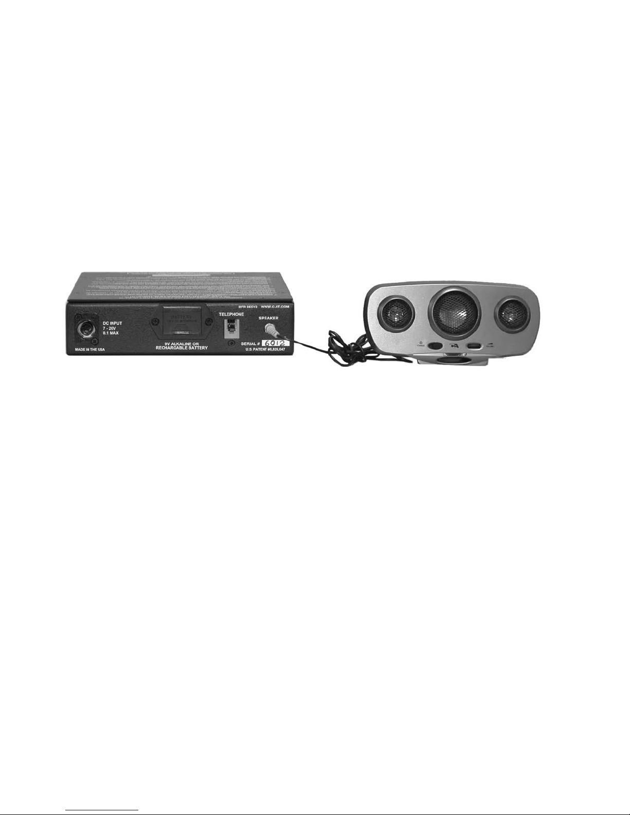
Connecting External Speakers
Connecting the ICRI to external speakers via the optional speaker assembly and cables permits the
user to continuously monitor all radio traffic crossing the ICRI. The two separate speaker jacks
allow the user to monitor both talk groups simultaneously.
To utilize the speaker function, connect the supplied speaker cable to one of the speaker jacks and
the input jack of your amplified speaker. Operate your speakers as normal, usin g their external
power source and on/off function to control volume level and output. The ICRI will function as
normal and does not require any modifications.
FIGURE 23: ICRI SPEAKER CABLE CONNECTED TO SPEAKER JACKS
ICRI Unit Identifier
The ICRI has a “ Unit/Voice ID” announcement that sounds every 10 minutes. Each I CRI delivered
has a unique ID (for example, “NJICS Northeast Region Box 201”). This func tion will not i nterr upt
any current audio activity, but will wait for activity to cease before sounding. The Unit/Voice I D is
also transmitted each time the ICRI is turned on.
If needed, this function can be temporarily muted. This unit has been configured with a THREE
position power switch. This switch serves three functions. It is used to turn the ICRI “ON” and “OFF” and
turn to the BRIDGE I D ON a nd OFF. There is no delay or “reboot” time when switching between the three
positions..
Up: Unit and BRIDGE ID ON
Center: OFF
Down: Unit ON, BRIDGE ID OFF
- 22 -
Page 23
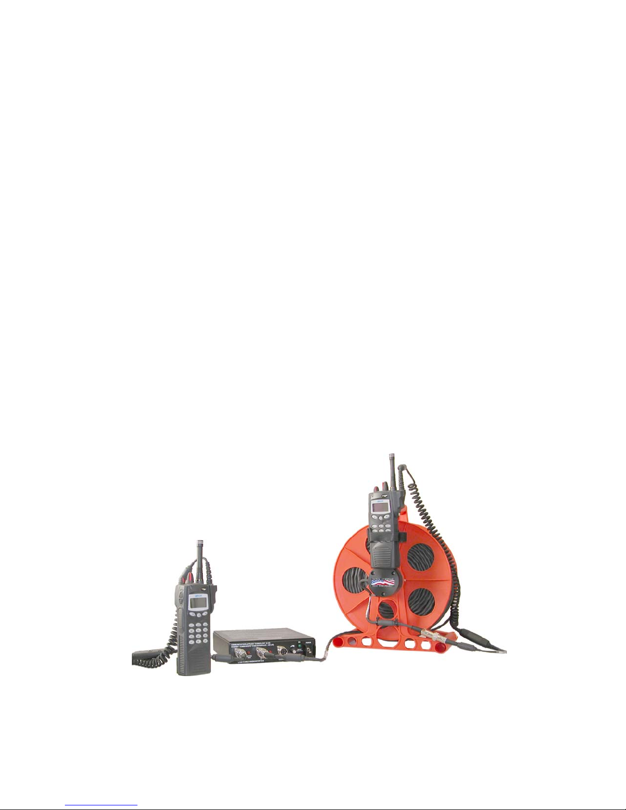
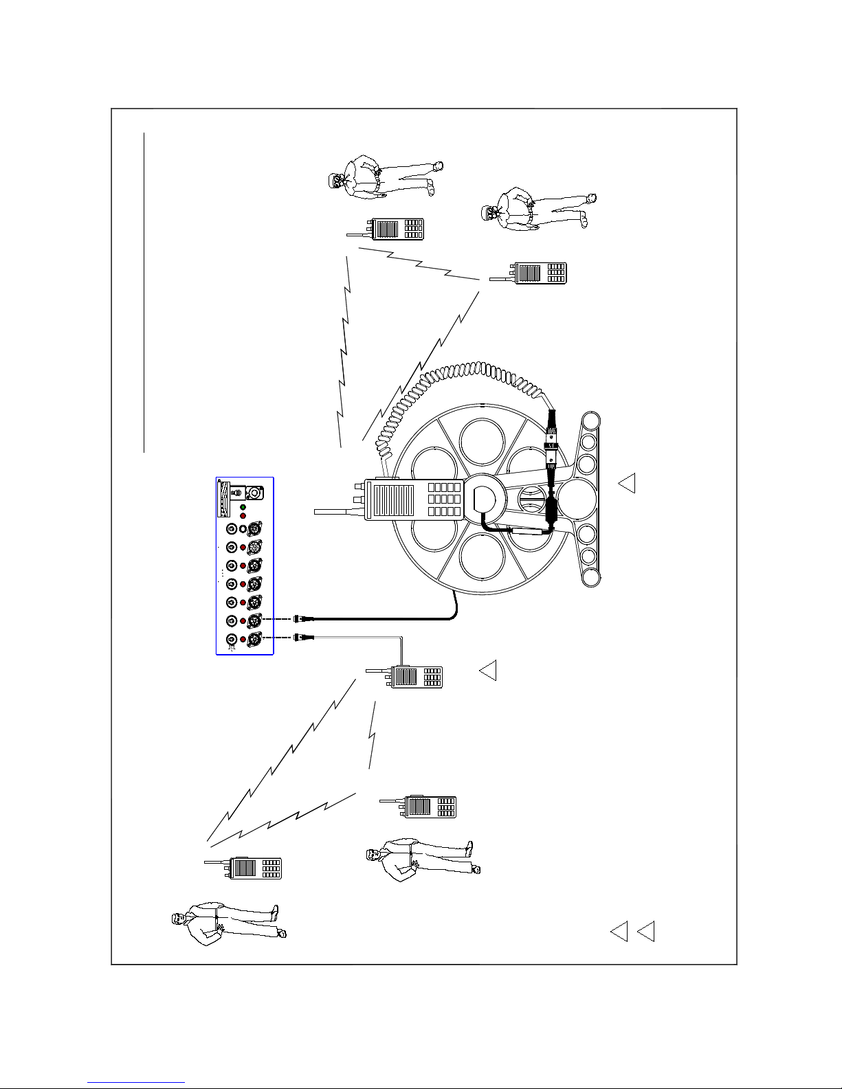
250’ Radio Extension Interface (Cable Reel) P/N 179.6213
Positioning one or more of the radios, to be connected to the ICRI at a distance greater than th e
length of the interface cable may be desirable for one of several operational reasons:
1. The personnel associated with a radio will be located inside a building for which there is
poor RF coverage from the ICRI’s location.
2. The personnel associated with a radio will be located inside a tunnel or other below grade
area for which there is poor RF coverage from the ICRI’s location.
3. Radios operating in very close pr oximity to one anothe r, neg ative ly affe ct the perf orman ce of
other another, such as receiver desensing.
The personnel—equipped with compatible radios—in the same general location of the reel-mounted
radio, will be able to communicate with those operating radios or the handset also connected to the
ICRI.
The extension cable is inserted between the ICRI and the radio interface cable that is usually
connected directly to one of the radio ports on the ICRI front panel.
NOTE: Multiple reels of cable can be linked together for requirement of greater distance than 250
feet. There will be no degradation of the communications link for up to 2000 feet of ca ble, B UT it
is important to note that if the cable is run near a source of high electrical energy, “noise” from
such a device can be expected to be induced into the cable and r educe---possibly significa ntly---the
quality of the communications.
It is strongly recommended tha t the ra dio link be tested befor e the pe rsonnel ente r the a rea of poor
RF propagation, so that any defects with the cable or the connections will be noted before a safety
issue arises--due to a lack of radio communications.
FIGURE 24: CABLE REEL CON N ECTOR
- 23 -
Page 24
Set-up of the cable-reel
Equipment required: ICRI, ca ble-reel, radio interface cable for radio to be placed in the area of poor
RF coverage.
1. Place the radio on the right angle support and secure it in-place with the Velcro™ strap.
2. Connect the cable end that exits from the side of the reel to the radio interface cable. Be sure
to align the keyway and secure the connectors together with the locking ring on the male
connector.
3. Connect the unspooled cable to a radio port on the ICRI. Be sure to align the keyway and
secure the connectors together with the locking ring on the male connector.
4. Unreel the desired length of cable—this may be all the cable if the distance is unknown.
5. If needed, connect additional cable reels between the ICRI and the first reel (up to eight for a
total distance of 200’ feet).
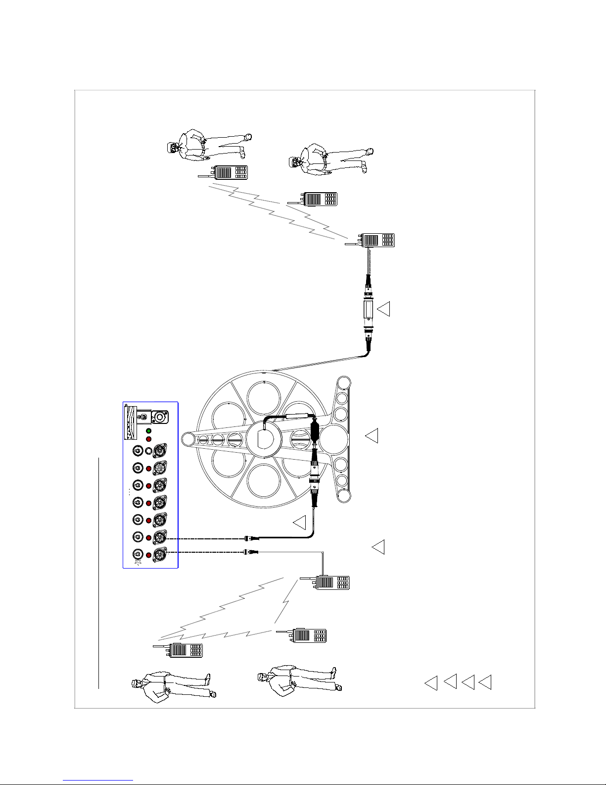
NOTE: If the cable will be used to place a radio in a stairwell, or on a building roof, hill or tree
top to enhance the operating range of the radio, then it may be preferable to have the cable reel
located beside the ICRI and the radio connected to the unspooled end of the cable. In this case,
reversal cables are needed.
Set-up of the cable-reel with reversal cables:
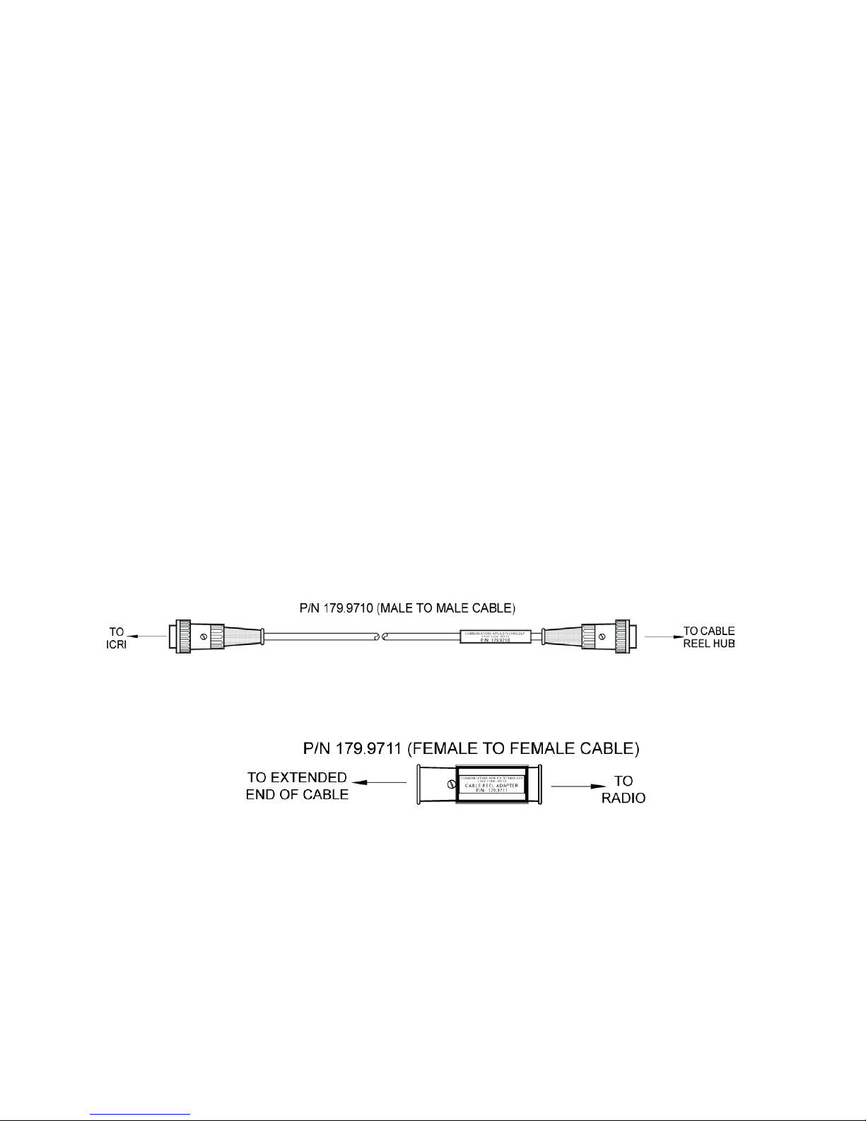
Attach one end of cable “A” to the male connector located near the center hub on the reel. Attach the
other end of cable “A” to an ICRI radio port.
A
Attach one end of adapter “B” t o the female conn ector at the “free” end of the cable. Attach the
other end of adapter “B” to a radio interface cable.
B
With this configuration, the cable reel will remain with the ICRI unit and the radio would travel to
the incident site or remote location for better operating range of the radio.
FIGURE 25: EXTENSION CABLE
- 24 -
Page 25
ICRI (ALL VERSIONS)
COMMUNICAT I ONS-APPLIED TE CHNOLOGY
CAGE COD E: 0EEY2
P/N: 179.9711
CABLE REEL ADAPTER
MAY BE A MOBILE RADIO
4
OR TRUNKED CHANNEL
CHANNEL 1 SIMPLEX
4
CHANNEL 2
SIMPLEX
CHANNEL 2
SIMPLEX
SIMPLEX
P/N 179.9711 REVERSAL ADAPTER "B"
1
TO RADIO
CABLE REEL
2
3
MULTIPLE REELS CAN BE CONNECTED TO EX TEND DISTANCE TO RADIO UP TO 2000 FEET. (ONLY 1 SET OF REV ER SAL ADAPTORS REQUIRED)
2
1
P/N 179.9710 REVERSAL ADAPTER "A"
CHANNEL 1 SIMPLEX
OR TRUNKED CHANNEL
OR TRUNKED CHANNEL
001-0692-2 SPECIAL OPS REEL AT ICRI CONFIGURATION
3
250 FEET
CHANNEL 2
COMMUNICATIONS - APPLIED TECHNOLOGY
(NOT TO SCALE)
INCIDENT COMMANDER WITH RADIO
CHANNEL 1 SIMPLEX
S.O./SURVEY TEAM
ICRI with Attachments
TACTICAL / 1 RESPONSE
ST
RADIO INTEROPERABILITY
TALK 2
MADE IN USA
ON
OFF
VOX
COMMUNICATIONS-APPL IED TECHNOLOGY (C-AT )
INCIDENT COMMANDERS' RADIO INTERFACE ( I C R I )
TM
TM
ACTIVE
TALK 1
1 2
INPUT VOLTAGE
LOW OK
LAND MOBILE RADIO INTERFACE
1 2 3 4 5
HANDSET
U.S. PATENT #6,826, 647CAGE CODE: 0EEY2 www.c-at.com
TELEPHONE
DC INPUT
7 - 20V
0.2A MAX
- 25 -
Page 26
ICRI (ALL VERSIONS)
CHANNEL 1 SIMPLEX
OR TRUNKED CHANNEL
MAY BE A MOBI L E RADIO
2
2
1
MULTIPLE REELS CAN BE CONNECTED TO EXTEND DISTANCE TO RADIO UP TO 2000 FEET.
CHANNEL 1 SIMPLEX
OR TRUNKED CHANNEL
CHANNEL 2 SIMPLEX
OR TRUNKED CHANNEL
TO RADIO
CABLE REEL
001-0692 SPECIAL OPS RADIOS AT REEL CONFIGURATION
1
250 FEET
CHANNEL 2 SIMPLEX
CHANNEL 2 SIMPLEX
COMMUNICATIONS - APPLIED TECHNOLOGY
(NOT TO SCALE)
INCIDENT COMMANDER WITH RADIO
CHANNEL 1 SIMPLEX
S.O./SURVEY TEAM
ICRI with Attachments
TACTICAL / 1 RESPONSE
ST
RADIO INTEROPERABILITY
TALK 2
MADE IN USA
ON
OFF
VOX
COMMUNICATIONS-APPLIED TECHNOLOGY (C-AT )
INCIDENT COMMANDERS' RADIO INTERF ACE ( I C R I )
TM
TM
ACTIVE
TALK 1
1 2
INPUT VOLTAGE
LOW OK
LAND MOBILE RADIO INTERFACE
1 2 3 4 5
HANDSET
U.S. PATENT #6,826,647CAGE CODE: 0EEY2 www.c-at.com
TELEPHONE
DC INPUT
7 - 20V
0.2A MAX
- 26 -
Page 27

APPENDIX D: PART NUMBERS FOR ICRI, ACCESSORIES AND RADIO
PORTABLE ICRI
GROUPS
NUMBER
ICRI-G2, 1 radio I/O port to MSAT G2 satellite radio only. Eliminates double PTT.
1
500.7500
INTERNAL 9V BATTERY
1
500.9286
padded carrying case
1
500.9250
padded carrying case.
2
500.9260
BACKPACKABLE VERSION.
2
500.9280
BACKPACKABLE VERSION.
2
500.9288
ICRI-1E 2 talk, 5 radio ports + 1 handset port + 1 telephone port
4
500.9288
ICRI, 5 radio I/O ports + 1 handset I/O port + 1 telephone I/O port.
4
500.9330
ICRI, 5 radio Post Standard Chassis w/mil-spec connector
4
500.9274
(includes audio buffer delays P/N 500.9311).
4
500.9336
RACK MOUNTABLE ICRI
configuration.
2
500.9261
mountable, (includes audio buffer delays P/N 500.9311),
2
500.9262
configuration (includes audio buffer delays P/N 500.9311).
2
500.9265
configuration (includes audio buffer delays P/N 500.9311).
4
500.9335
CABLES
ICRI Configurations
ICRI-2P, 2 radio I/O ports + 1 handset I/O port + 1 RJ22 phone I/O port, WITH
ICRI, 5 radio I/O ports + 1 handset I/O port + and 1 telephone I/O port, with
ICRI, 5 radio I/O ports + 1 handset I/O port + 1 telephone I/O port, supplied with
ICRI-WF, 5 radio I/O ports + 1 handset I/O port + and 1 telephone I/O port,
ICRI-1.3, 5 radio I/O ports + 1 handset I/O port + and 1 telephone I/O port,
ICRI, 10 radio + 1 handset + 1 telephone I/O port in PelicanTM 1550 configuration
TALK
PART
ICRI, 5 radio + 1 handset + 1 telephone I/O port in 19", 2 U high, rack mount
ICRI, 10 radio ports+1 handset I/O port and 1 telephone I/O port, 3U X19”, rack
ICRI, 10 radio + 1 handset + 1 telephone I/O port in 19", 2 U high, rack mount
ICRI, 10 radio + 1 handset + 1 telephone I/O port in 19", 2 U high, rack mount
- 27 -
Page 28

POWER OPTIONS
PART
NUMBER
ICRI to 8 “AA” battery pack adaptor cable (use with 160.3611)
180.0450
8 “AA” battery pack (requires 180.0450)
160.3611
DC input cable, dual mode (alligator clips and vehicle cigarette lighter plug)
179.0730
DC Input Cable w/ Neutrik Connector one end, S&T, 15' LG
179.0731
customized for other radios.
179.0759
115V AC adaptor (in-line switching power supply)
320.0431
Internal rechargeable LiIon battery (use with 500.9280)
500.9281
TRANSIT/STORAGE CASES OPTIONS
Waterproof case (PelicanTM 1550) with fitted foam insert
990.0602
Waterproof case (PelicanTM 1600) with fitted foam insert
990.0601
connection
990.0603
Waterproof Case(Pelican 1400) without foam
990.0609
MISC OPTIONS
any radio interface cable)
179.6213
Portable speaker, battery or AC powered with audio and power adapter cables
131.0155
Radio port to speaker cable
178.0200
Telephone port to speaker cable
178.0652
8 pin DIN(telephone port) to speaker cable
179.0653
ICRI-to-ICRI link cable to expand # of linked radios
179.0656
ICRI-to-ICRI dedicated link port (RJ-45 connector) interface cable
179.0692
ICRI, RJ - 45 link port to dual talk speaker port adapter
179.0696
MODIFIED RJ 22 "LISTEN ONLY" COILED CORD
179.0697
ICRI-to-ICRI link port (RJ-45 bulkhead connector) (includes link cable P/N 179.0692)
179.0800
Four talk group link configuration switch
179.0810
250’ universal extension cable upgrade to slip ring version
179.6000
ICRI handset with noise-canceling mic, PTT bar, and coiled cord
280.0125
Lightweight headset with supra aural speaker and boom-mounted microphone
281.9137
Remote headset jack with push-to-talk switch/hot mic-PTT switch 20' coiled cord
295.0150
Peltor to ICRI adaptor cable and phantom power supply
295.3000
Remote (RF) control functions (DTMF)
500.9291
Unit ID broadcast (Custom Digitized Voice Message)
500.9292
Message)
500.9293
All call function with customized alert tone(for rack-mount ICRI only)
500.9297
All call function without customized alert tone (for rack-mount ICRI only)
500.9298
Audio buffer delay for all radio ports
500.9311
Speaker port for use with amplified speakers or recording devices (3.5mm jack)
500.9312
Radio interface extension cable (10 feet)
179.6206-10
ICRI Options
External power, 20' interface cable with alligator clips 179.0758
Battery eliminator assembly for Pelican 1610 ICRI and 5 XTS-1500 radios, may be
Waterproof case (PelicanTM 1610) with fitted foam insert , 5 antenna connections, power
250’ universal extension cable with reel, slip ring, and radio “holder” (used in conjunction with
Remote RF control functions (DTMF) with Unit ID Broadcast (Custom Digitized Voice
- 28 -
Page 29

TELEPHONE OPTIONS
NUMBER
Telephone handset, SAT phone, INMARSAT (generic, acoustic coupler) interface cable
179.0655
Direct connection cable to generic, 2.5 mm plug cellular telephone headset jack
179.0672
Direct connection for modular handset jack interface cable for ICRI, din connection
179.0676
2.5mm to RJ 10 interface cable and Sectera secure phone
179.0693
Direct connection interface cable to generic, 2.5 mm plug cellular telephone jack for use with
RJ series port P/N 179.0801
179.0693
NOKIA 5100, 6100, 7100 interface for ICRI
179.0760
cable P/N 179.0693)
179.0801
Direct connection cable to NokiaTM cellular telephone headset jack
179.0802
Iridium LEMO adaptor interface cable
179.0806
Iridium Satellite phone Lemo adapter for DIN phone interface cable
179.0806
MSV G2 interface cable for radio PTT mode
179.1204
PSTN Analog telephone (RJ-11) Internal circuit with auto-answer
500.9290
CABLE REEL ADAPTOR OPTIONS
Adapter - Reel at ICRI - Handset Port to Cable Reel
179.6217
Adapter - Reverse Gender - Male to Male
179.6208
Adapter - Reverse Gender -Female to Female
179.6209
Adapter - Reel at ICRI - Cable Reel to Handset
179.6218
Adapter - Reel down Range - Handset Port to Cable Reel
179.6219
Adapter - Reel down Range - Cable Reel to Handset
179.6220
ANTENNAS
INTERNET/COMPUTER OPTIONS
Functions. Two Talk Group Configuration.
500.9304
ATA VoIP interface with DTMF keypad
500.9295
VOIP interface without DTMF keypad
500.9296
Functions. Four Talk Group Configuration.
500.9305
Direct connection modular telephone handset jack (RJ series -for cell phone connection use
PART
VHF 1/4 wave, magnetic-mount antenna 125.0601
UHF 1/4 wave, magnetic-mount antenna 125.0602
800MHz 1/4 wave, magnetic-mount antenna 125.0603
Network based computer control of ICRI. Controls Talk Group settings and All Call
Network based computer control of ICRI. Controls Talk Group settings and All Call
- 29 -
Page 30

Interface Cables for Standard DIN Connector ICRI
BENDIX KING™ Relm
PART
NUMBER
EMV Mobile interface cable
179.0669
EMH/GMH/LMH series interface cable
179.0670
EP, LP, GP series, PRC 127 interface cable
179.0671
DPH 50102S-04 interface cable
179.0744
EMU Mobile series interface cable
179.0674
EPU, LPV series interface cable
179.0675
DPU (P-25) interface cable
179.0745
Relm RPU/RPV 416 series interface cable
179.0643
PRC-127 radio interface cable**use 179.0671
179.0740
DATRON™
G25RPV100 Guardian interface cable, Datron G25AP5001
1179.2730
G25RMV100 interface cable
179.G25RMV
EF JOHNSON™
EF Johnson™ 7780 and Motorola™ T5000 interface cable
179.0847
5300 series interface cable
179.0642
8500 series (VIKING) interface cable
179.0742
9755 interface through speaker mic port interface cable
179.0820
9755 interface through accessory port interface cable
179.0821
MPA radio interface cable/amplifier
179.0660
MRK radio interface cable/amplifier
179.0661
LPE 200 radio interface cable/amplifier
179.0662
MA/COM COM-NET ERICSSON - EDACS 300P
179.0665
500M interface cable
179.0668
Panther 500P and KPC radio interface cable/amplifier
179.0732
Jaguar 700P, P7100, and P7200 series radio interface cable/amplifier
179.0733
Panther 600 radio interface cable/amplifier
179.0738
affected by ICRI link) 37 pin
179.0743
P5400/5450 series radio interface cable/amplifier
179.5300
FIRECOM interface cable, Accessory plug to radio port
179.1197
Firecom Intercom Telephone port to ICRI cable, (2) 3.5mm plugs to 8 pin din
179.1206
ERICSSON™ MA/COM™
Orion mobile interf ace cable (“Y” cable/box so normal func tion of radio microphone is not
FIRECOM™
- 30 -
Page 31

ICOM™
F50/F60/F80 interface cable
179.016
F3, F3S, F4, F4S, F4TR, F10, IC-H2, H6, J12, M5, U12, U16 interface cable
179.0737
F11, F11S, F14, F21, F21S, F33GS, F33GT, F43GS, F43GT, F43TR interface cable
179.0748
F3G, F3GS, F4G, F4GS interface cable
179.0749
ICOM™F30G, F30GS, F40G, F31GS, GT, M88, M87 interface cable
179.0754
A3 interface cable
179.0826
A200 interface cable
179.0827
ICOM A110, F 320/402/410/420/601/610/1010/1020, F420 interface cable with OPC617 adaptor
interface cable
179.4200
ICOM™ IC-F1821D interface cable
179.F1821
ICOM™ IC-F70DT interface cable
179.F70DT
KENWOOD™
TK190, 280/290, 380/390 480/481, 2140/3140, 2180/3180, 5210, 5400 radio interface cable
179.0136
TK 690/790/890 radio interface cable
179.0679
TK 780/880 and KCT-19 interface cable
179.0770
TK 760/780/880 and KCT-19 interface cable
179.0771
TK 880 hand mic/rear speaker interface version
179.0830
TK 6110 interface cable
179.0832
TK 8150 interface cable, ("Y" cable/box so normal function of radio is not affected by ICRI link)
179.0870
TK 8150 interface cable for use without handset
179.0871
272G/372G, 3130/3131
179.6013
TK 5710 interface cable
179.TK5710
TK 208, 220, 240D, 248,250,260,270,308, 320,340D, 348, 350, 353, 360, 370, 430, 431,
- 31 -
Page 32

MOTOROLA™
MX-300/350 interface cable
179.0121
MARATRAC, SPECTRA 44/50 PIN interface cable
179.0161
EX500/600 interface cable
179.0601
5000, XTS-1500, XTS-2500 and EF Johnson 5100 interface cable
179.0630
GTX, LTS 2000, CP 200, GP 300, P 1225 portable radio interface cable, SP50
179.0634
MCS-2000 interface cable (“Y” cable/box so normal function of radio is not affe cted b y ICRI l ink)
179.0635
Spectra interface cable (“Y” cable/box so normal function of radio is not affected by ICRI link)
Customer needs to specify 15 pin or 25 pin
179.0636
MICOM 2E (HF) interface cable
179.0638
VISAR interface cable
179.0639
RADIUS P-200 interface cable
179.0640
STX, STX-800, STX-821 series interface cable
179.0680
Radius M1225 Mobile interface cable
179.0690
CDM 1550 with RJ 45 connection
179.0698
ICRI interface to Motorola TRBO
179.0708
Astro/Saber, Saber I, II, and III interface cable
179.0710
HT 750, HT 1250, MTX 8250 interface cable
179.0735
Motorola™ Maxtrac 20 pin interface cable
179.0739
Motorola XTVA Vehicle Radio interface cable
179.0790
Motorola™ T5000 intercom interface cable
179.0847
Interface Cable for Motorola MTP850
179.0850
Motorola™ MC-900, interface cable for ICRI
179.0890
XTL 5000 adapter (uses 15 pin Spectra) interface cable
179.0931
XTL 5000 adapter (to use with 179.0636-15) interface cable
179.0931
XTL 5000 W4 interface cable
179.0932
XTL 5000 direct interface cable with ignition sense and speaker leads
179.0933
XTL5000, XTL 2500, XTL 1500, PM 1500 w/ speaker and ignition leads
179.0933
XTL 2500 interface cable
179.0935
PM1500 interface cable with speaker and ignition sensing leads
179.0936
XTVA interface cable
179.1911
XTVA interface cable (suitcase version)
179.1913
GP 350 interface cable
179.6018
PR400
179.6020
MD XPR 6550 interface cable
179.6550
NEXTEL™
i1000, R750 cell phone/radio interface cable for iDEN mode
179.0678
i205, I305, I530, I730 cell phone/radio interface cable for iDEN mode
179.0883
MT-2000, JT-1000, HT-1000, MTS-2000, MTX-6000, MTX-838, MTX-8000, XTS-3000, XTS-
MT-1000, HT-600, HT-2000, MT-300, MTX-800, MTX CLASSIC, MTX-820S, MTX-900 &
Maxtrac, CDM-1250, GM 300, GM 350, GM 600, CM 200, CM 300, G TX 800 Mobile, and
SP10/21, XTN446/500/600, Pro 1150/2150, CP100, PMR446, XU1100/2600, CLS 1110/1410,
- 32 -
Page 33

YEASU/VERTEX™
VX-500/510/520 and Maxon SP 120/30/40 interface cable
179.0138
MAXON SP2550/2850,SL70W,EP4800/TP4800/TP4801
179.0139
VX-600/800/900 interface cable
179.0741
VX 10/300/400/VXF-1 interface cable, VX-210, 210A 131, 160, 180, 410, 420
179.0746
Standard Vertex™ Radio HX340 interface for ICRI
179.0747
Yaesu/Vertex™ VX-7R interface cable
179.0751
Standard Horizon HX-230/240/250/255 Interface cable
179.0752
Yaesu/Vertex™ series VX 820/920 interface cable
179.092
VX 3000/3100/3200 interface cable
179.0924
Yaesu/Vertex™ Standard # FPH2070 interface cable
179.207
VX-420 interface cable for ICRI, Same as 179.0746
179.2100
VX 4000, 4204 interface cable
179.965
VX 4100/4200 Interface cable
179.9652
HX581T interface cable
179.CMP
TAIT™
TOPA-AA-0036 interface cable
179.0860
Interface to Tait Orca Radio interface cable
179.0917
TAIT 8000/8200 interface cable
179.1189
TM9155 interface cable
179.TM9155
TP9160 interface cable
179.0916
Thales™ P25 radio interface cable
179.0622
Body Wire interface 3.5 mm to 5 pin interface cable
179.0004
works with radio having 5 or 6 pin jack connectors
179.0600
PRR interface cable
179.0603
disassembly
179.0734
Tekk XT-800 interface cable
179.0799
FRS interface (Radio Shack, Motorola etc) 089-1171
179.0910
Bowman interface cable
179.0950
Midland™ MO-1032 interface cable
179.1032
Ritron Model JMD-Xn interface cable
179.8087
ALINCO DJ 596 interface cable
179.DJ596
Yaesu/Vertex™ series VX-210, VX-210A, VX-400, VX-131, VX-160, VX-180, VX-410, VX-417,
MISCELLANEOUS CABLES
SINCGARS, PRC-117, MBITR and other “green gear” radio interface cable (U-229/U connector
Universal radio interface cable (requires radio speaker/mic assembly to be provided for
NOTE: Please contact C-AT if you require an interface cable for a radio not listed or for current
pricing and options
- 33 -
Page 34

APPENDIX F: FCC 15.21 INFORMATION TO USER:
Caution! Change or modification not expressly approved by the party Communications-Applied
Technology could void the user’s authority to operate the equipment.
15.105(b) Information to User:
NOTE: This equipment has been tested and found to comply with the limits for a Class B digital
device, pursuant to part 15 of the FCC Rules. These limits are designed to provide reasonable
protection against harmful inte rference in a residential installation . This equipment gene rates, uses
and can radiate radio frequency energy and, if not installed and used in accordance with the
instructions, may cause harmful interference to radio communications. However, there is no
guarantee that interference will not occur in a particular installation. If this equipment does cause
harmful interference to radio or television reception, which can be determined by turning the
equipment off and on, the user is encouraged to try to c orrect the interference by one or more of the
following measures:
1. Reorient or relocate the receiving antenna.
2. Increase the separation between the equipment and receiver.
3. Connect the equipment into an outlet on a circuit different from that to which the receiver is
connected.
4. Consult the dealer or an experienced radio/TV technician for help.
- 34 -
 Loading...