


Table of Contents
•Tools and Material Requirements…………………………………..2
•M2M-W02 Unit Overview……..…………………………………. 3
•M2M-W02 LED Overview …… ………………………….………4
•M2M-W02 Installation Overview…………………………….…..5
•Step by Step installation …………………………………………... 6
-Aligning and Mounting the unit………………….………..6
-Pulling Wires…………………………….………….….…..7
-Connecting Wires……………………………….…..……..7
-Clean up and weather protect………………………...….9
-Calibration………………………………………..….……..9
-Verification…………...………………….…………..……10
1
M2M-W02 (Wireless Monitor Controller)
INSTALLATION GUIDE
This is a Step by Step guide to help you correctly install the M2M-
W02 controller. Please note that not all sites are the same, and
that this guide only deals with a couple of site possibilities.
Tools and Material Requirements:
•Flat head screwdriver
•Small Phillips head screwdriver
(preferably magnetic)
•Open end connectors (minimum
of 8 per site)
•Female connectors (minimum of 4
per site)
•Drill with approximately 13/16
hole bit, or multi hole bit.
•Silicone tube w/ gun
•3 to 4 self tapping metal screws
•Nipple w/ nut to pull wires through
•Wire cutter, stripper, and crimper
2
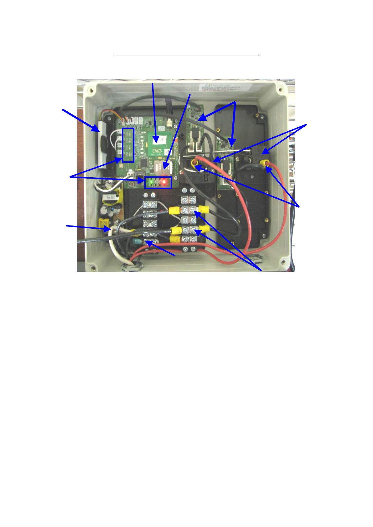
Battery
LED’s
Neutral
M2M-W02 Unit Overview
Cellular Module
SIM card
Current Sensors
Relays
Relay
Outputs
Power
Relay Inputs
Battery: So the controller will stay online in case utility power is lost
Current Sensors: Measures the amp reading during each on/off cycle
Cellular Module: Communicates with the cellular network to send and receive data
SIM card: Is the unique cellular address specific to the controller (same as a phone number)
Relays: The main control for turning the lights on and off
Relay Outputs: Wires going to the lights, once relays are activated voltage will flow throw these
wires to the lights.
Relay Inputs: Coming off the breakers to the relays, source voltage to the lights
Power: Connects to the Utility power from the breaker to power the controller
Neutral: Return path for the voltage, connects with the neutral from the breaker box
LED’s: Indicators to let you know what the controller is currently doing at any given time.
3
Relay
“on”
signal
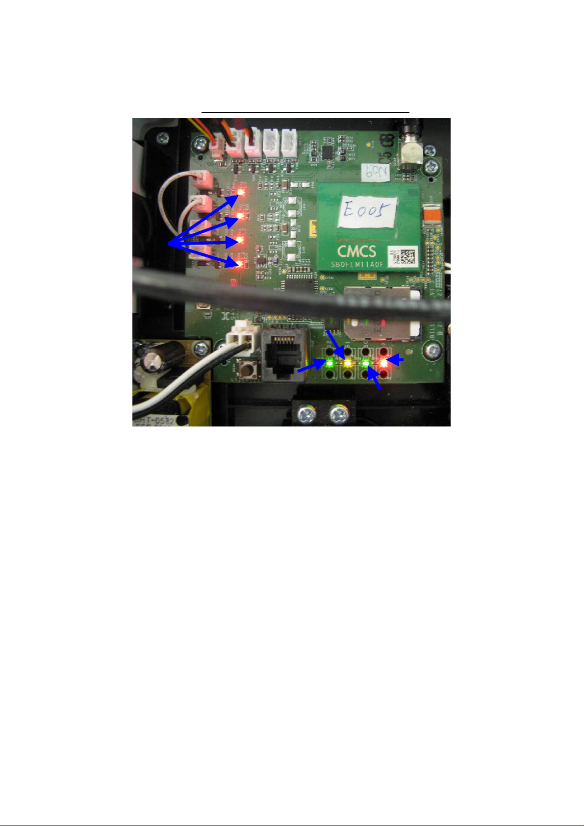
LED’s Overview
Cellular
Connection
Receiving signal
Utility
Power
System Heartbeat
• Utility Power: (Red LED) Solid when the controller is connected to utility power
• System Heartbeat: (Green flashing LED) Flashes whenever the system is powered and
operating properly
• Receiving Signal: (Yellow LED) Shows when the controller is currently receiving a message
• Cellular Connection: (Green LED) Flashes if the controller is trying to connect or Solid when
connected to a cellular connection
• Relay “on” signal: (Red LED’s) Solid if the corresponding relays are on
During the calibration process there are a couple of combinations to the LED’s that also mean
something:
• When you receive system information messages you will notice that the Yellow LED will first
turn on showing it is receiving a message, but then both the middle LED’s will then flash
together for about 1 minute while it processes the message.
• Also, after you press the calibrate button the middle two LED’s should flash rapidly together
for about 20 minutes while the lights are warming up. And that is also when the Relay “on”
LED’s should also light up
4

Installation Overview
1. Activate the SIM card in the M2M-W02 monitor.
2. Turn all breakers off.
3. Determine where to mount the M2M-W02 monitor based on the site. Select a location where the M2M-W02 can
be mounted firmly in place, not interfere with access to (or the operation of) other equipment and where you will
have easy access to the required utility power.
4. Mark where to make a hole through the M2M-W02 enclosure for mounting.
5. BEFORE DRILLING any holes in the M2M-W02 enclosure remove the base plates inside the M2M-W02 monitor
with a magnetic Phillips head screwdriver (7 small screws).
6. Once the M2M-W02 enclosure is empty, drill the hole you marked in Step 4 through the enclosure and the
breaker box and drill 3 or 4 self-tapping screws into the M2M-W02 enclosure for mounting.
7. Securely mount the M2M-W02 enclosure to the breaker box and replace the base plates.
8. Pull wires through the True Tracker: Controller AC; Neutral; Relay Inputs (from circuit bre aker to relay) and
Relay Outputs (from relay to lights).
9. Refer to the wiring diagram that matches the site configuration and connect each wire inside the M2M-W02
enclosure as shown in the wiring diagram.
10. Seal the outside edges of the enclosure with silicone to protect from the environment.
11. Wrap the wires into the breaker box with electric tape or a tie wrap so they are neat and easy to work with in the
future.
12. Turn circuit breakers back on (Look for red and green LEDs to illuminate inside of the M2M-W02 monitor)
13. After the red LED inside of the M2M-W02 monitor is illuminated, plug in the Battery
14. After the green LED stops flashing and is solid green the M2M-W02 monitor has connected to the cellular
network.
15. Call Commtiva Technology Corp. to have information sent to the M2M-W02 monitor to enable it for operation.
You will need to provide site and location information such as number of panels, number of lights on each panel
and the SIM card number associated with the M2M-W02 Monitor.
16. Once the M2M-W02 monitor receives the required information the Yellow LED will light up.
17. Shortly after the Yellow LED illuminates the 2 middle LEDs (1 will be Yellow and 1 will be green) will flash
simultaneously for about 1 minute.
18. Once the 2 middle LEDs (1 will be Yellow and 1 will be green) stop flashing press the Brown calibrate button on
the main controller board. This will turn the billboard lights on for 20 minutes. During this time the 2 middle LEDs
(1 will be Yellow and 1 will be green) will flash rapidly and the relay “ON” LEDs will light up.
– SEE LED’s Overview on previous page
19. Verify that the M2M-W02 monitor is operational by confirming that the billboard lights are ON, or use an amp
clamp or current meter to see if the output wires are drawing any current. If the lights are on they should be
drawing current. You can figure about 4 amps per bulb on a 120V setup or 2 amps on a 240V setup.
20. After you have verified the M2M-W02 monitor is operational fasten the enclosure lid securely so no moisture can
get in.
5

STEP BY STEP GUIDE
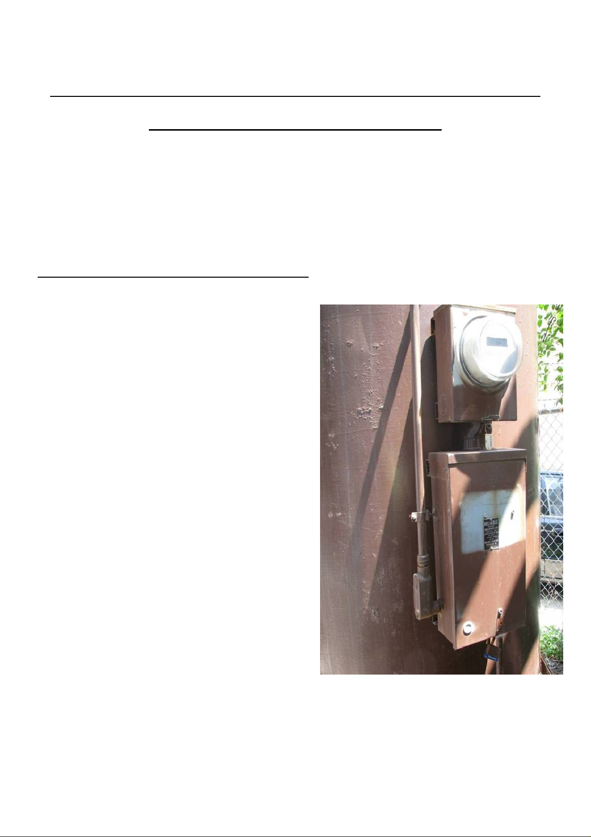
As soon as you reach your work area the first thing
you should do is shut off each breaker to avoid
electrical shock (Illustration 6.1). You can also take
the top cover off of the M2M-W02 unit right away.
Keep in mind what is behind the door, as
there are only two places you can drill a
hole in back of the M2M-W02 enclosure
(see the red circles in Illustration 6.3). Try
to make it easy to reach each all of the
wires you need: Utility power, Neutral,
inputs and outputs off the relay(s).
In order to drill a hole you must take off
the base plates inside the enclosure, to
avoid damaging any parts while you drill
the hole.
Illustration 6.1 Illustration 6.2
Aligning and Mounting the Unit
Once the breakers are off a good place to start is to
find out where to mount the unit, in this example
(Illustration 6.2) it is mounted on the front of the
box. But in other cases it will also fit on the side or
the bottom of the box. Where it is mounted doesn’t
matter as long as it fits and can be mounted firmly.
If you are installing the unit on the front as shown,
be sure to leave room and extend the wires a bit
longer to allow the door to open and close with
ease.
6
Illustration 6.3
Be sure to mark where your going to drill
the hole before you take off the base plates.
(Illustration 6.3) There are 7 small screws
(blue circles in Illustration) that hold the
base plates on. It is best to use a magnetic
Philips screwdriver for these screws
because of their size.
The hole can be drilled in either the right or
left opening.
Be sure to also drill 3 or 4 self-tapping
screws into the box to mount it firmly. Once
it is mounted firmly you can then replace
the base plates that you took out earlier.

Pulling Wires
The example on the left is a 240v single face
board. So you will only need 6 wires to go from
the box and into the M2M-W02 Module. For
each additional relay in the box there will be 4
more additional wires to go to the M2M-W02
module on a 240v system (2 relay inputs and 2
outputs).
One of the wires you will need is utility power,
coming from the auxiliary breaker.
Connecting Wires
Now it is time to connect the wires to the
controller. (refer to Illustration 7.2) Begin by
pulling each wire through the hole you created
into the enclosure. The Utility power and
neutral will hook up next to each other on the
first connector block. Each will use an open end
connector. On the True Tracker, black is for the
power and white is for neutral.
The relay input wires will connect into the next
connector block using an open end connector.
For a detailed diagram on how you wire
different configurations please refer to the wiring
and configuration diagrams provided in the
Quick Install Guide that is in every M2M-W02
box.
The relay outputs will connect into the relays on
the module using a female connector.
Illustration 7.1
The relay inputs come off the breakers and
go to the relay inside the box (Illustration
7.1). Refer to the example on the right. You
will need one relay input for each relay in the
True Tracker. You will also need an output
wire for each relay that will deliver the
electricity to the lights when the relays are
on.
Another wire that you will need to go into the
unit is the neutral. Make sure that the exposed
copper is not corroded if you are using the
original wire.
Neutral (white)
Illustration 7.2
Utility power (black)
Relay outputs
Relay inputs
While making all of these connections inside the
True Tracker, try to keep each individual wire
neat and tucked away to prevent any
complications with future repairs.
7

North
15A
South
15A
East
15A
West
15A
120V 4Panel
Neutral
To lights
Auxiliar
y
15A
Neutral
R
3
Pan
el 4
S
3
R
2
Pan
el 3
R
0
S
2
Pan
el 2
R
If you have a 2 or more face board
however the order in which you
connect the wires does matter. In
this example (refer to Illustration
R0R1R2R3
S0
S1
S2
S3
8.1) you will see 4 relays inside the
M2M-W02 module. If you were to
have a 4 face board you would
connect the lowest panel number to
Relay 0 or “R0”. And the highest
S
0
panel number to relay 3 or “R3”
For Example if the panel numbers
were 2111, 2112, 2113, and 2114.
2111 relay outputs would connect
to R0 while 2112 would connect to
S1
1
R1, 2113 to R2, and 2114 to R3.
As for the relay input wires simply
follow from the relay to the
connection block to see which
Pane
wires match up.
l 1
Illustration 8.2 is a 2 face
board 240v. Again the
lower panel number would
go to the lower relay
numbers.
For example, if your panel
numbers where 2140 and
2141. Panel 2140 would
connect to R0 an R1 while
panel 2141 would connect
to R2 and R3.
Also keep in mind that
these relays are not
actually numbered and this
diagram is simply for
reference.
NORTH
30A
Nort
h
30A
SOUTH
30A
Sout
h
30A
Auxiliar
y
15A
240V 2Panel
R0R1R2R3
S0
S1
S2
S3
S0
R0
Neutral
S2
R3 R2 R1
Pane
8
l 2
Pane
l 1

Clean up and Weather Protect
Once the unit is wired make sure to seal around
the entire enclosure with silicone to prevent
moisture from getting inside. (refer to Illustration
9.1)
Be sure to remember to plug in the battery after
you turn the power on and you see the red light
on the controller board.
Illustration 9.1
Now would also be a good time to make
everything neat and easy to work on next time it
may need maintenance. This may also prevent
wires from stretching or breaking every time the
door is opened. You can also turn the power
back on at this time.
Illustration 9.4
Calibration
Once you have the power turned on you will
notice two lights right away, the red light, which
is utility power and the green light, which
indicates whether or not the module is
connected to a cellular network. If the green
light is flashing that means it is trying to connect
and once it is solid means it is connected.
Once it is fully connected to a cellular network
you can then get the information sent to the
module. (refer to LED overview for LED
information)
To get the information sent to the controller
please contact Commtiva via telephone
(815)344-0678. Commtiva will need to know
the panel numbers, how many lights are on
each panel the location of the board, and the
SIM card number. They will then program the
controller and set it up for operation. You will
know when the controller has received the
information when the yellow light on the board
turns on.
Illustration 9.2 Illustration 9.3
9

The 2 middle LED’s should then flash
simultaneously for about 1 minute. Once they
stop flashing together you can then press the
Brown calibrate button. (Blue circle in Illustration
9.4)
After you press the calibrate button on the
M2M-W02 board and you have verified that it is
working properly you can now put the cover
back on the unit make sure the lid is fastened
securely to ensure no moisture can get in.
Once the button is pressed you will notice red
LED’s turn on for each relay.
Pressing the calibrate button will turn on the
billboard lights for 20 minutes to allow them to
warm up. During this time the middle 2 LED’s
should flash rapidly. The module will then go
through a 10 minute sampling to take a current
reading and calibrate itself. You do not have to
wait for the module to complete this warm up
before you verify that it is working.
Verification
A quick and easy way to see if the module is
working is to see if the lights are turned on after
you press the calibrate button. Usually during
the daytime however it is hard to tell if they are
on.
The other easy alternative is to use an amp
clamp or current meter (refer to illustration 10.1)
to see if the output wires are drawing any
current. If the lights are on then they should be
drawing current. You can figure about 4 amps
per bulb on a 120V setup, or 2 amps on a 240V
setup.
Congratulations on installing the M2M-W02
successfully!
Illustration 10.2
10
Illustration 10.1

FEDERAL COMMUNICATIONS COMMISSION INTERFERENCE STATEMENT
This equipment has been tested and found to comply with the limits for a
Class B digital device, pursuant to Part 15 of the FCC Rules. These limits
are designed to provide reasonable protection against harmful
interference in a residential installation. This equipment generates, uses
and can radiate radio frequency energy and, if not installed and used in
accordance with the instructions, may cause harmful interference to radio
communications. However, there is no guarantee that interference will not
occur in a particular installation. If this equipment does cause harmful
interference to radio or television reception, which can be determined by
turning the equipment off and on, the user is encouraged to try to correct
the interference by one or more of the following measures:
– Reorient or relocate the receiving antenna.
– Increase the separation between the equipment and receiver.
– Connect the equipment into an outlet on a circuit different from that to
which the receiver is connected.
– Consult the dealer or an experienced radio/TV technician for help.
CAUTION:
Any changes or modifications not expressly approved by the party
responsible for compliance could void the user's authority to operate the
equipment.
This device complies with Part 15 of the FCC Rules. Operation is subject
to the following two conditions:
(1) This device may not cause harmful interference and
(2) This device must accept any interference received, including
interference that may cause undesired operation.
FCC RF Radiation Exposure Statement
This equipment complies with FCC RF radiation exposure limits set forth for an
uncontrolled environment. This equipment must be installed and operated in
accordance with provided instructions and must not be co-located or operating
in conjunction with any other antenna or transmitter. End-users and installers
must be provide with antenna installation instructions and transmitter operating
conditions for satisfying RF exposure compliance.
RF exposure warningThis equipment must be installed and operated

in accordance with provided instructions and the antenna(s) used for
this transmitter must be installed to provide a separation distance of
at least 20 cm from all persons and must not be co-located or
operating in conjunction with any other antenna or transmitter.
End-users and installers must be provide with antenna installation
instructions and transmitter operating conditions for satisfying RF
exposure compliance
 Loading...