

Page 1
Software Reference Guide
Revision 11/07/2013
Page 2

Spotcheck Reference Guide
Page 3

COPYRIGHT © 2013 Bently Nevada, Inc & GE Energy (New Zealand) Ltd.
All rights reserved.
No part of this document may be reproduced, stored in a retrieval
system, or transmitted in any form or by any means, electronic,
mechanical, photocopy, recording or otherwise without the prior written
permission of Bently Nevada.
The information provided in this document is subject to change without
notice. Names and data used in examples are fictitious unless otherwise
noted. This document is distributed as is, without warranty of any kind,
either expressed or implied, respecting the contents of this document,
including but not limited to implied warranties for the document’s
quality, performance, merchantability, or fitness for any particular
purpose. Neither GE Energy (New Zealand) Ltd, nor its employees,
dealers, agents or distributors shall be liable to the user of this document
or any other person or entity with respect to any liability, loss or damage
caused or alleged to be caused directly or indirectly by this document.
Disclaimer
Information in this document is subject to change without notice. Names
and data used in examples are fictitious unless otherwise noted. This
document is distributed as is, without warranty of any kind, either
expressed or implied, respecting the contents of this document,
including but not limited to implied warranties for the document’s
quality, performance, merchantability, or fitness for any particular
purpose. Neither GE Energy (New Zealand) Ltd nor its employees,
dealers, or distributors shall be liable to the user of this document or any
other person or entity with respect to any liability, loss, or damage
caused or alleged to be caused directly or indirectly by this document.
Spotcheck Reference Guide
Page 4

Contents
SECTION 1: INTRODUCTION .......................................................................... 1
PRODUCT SUPPORT ...................................................................................................................1
ISO 10816-3:2009 Category and Definition .......................................................1
PRODUCT OVERVIEW .................................................................................................................2
STANDARD FEATURES ................................................................................................................3
UNITS OF MEASURE ...................................................................................................................4
STANDARD KIT ITEMS ................................................................................................................4
PRECAUTIONS..............................................................................................................................5
INSTRUMENT INPUT AND OUTPUT PORTS ..............................................................................6
FRONT PANEL..............................................................................................................................7
BATTERY PACK ............................................................................................................................8
Charge Battery Pack......................................................................................................8
Remove Battery Pack ....................................................................................................9
SECTION 2: INSTRUMENT BASICS ............................................................... 10
POWER ON/OFF ...................................................................................................................... 10
ACCELEROMETER SENSOR ..................................................................................................... 11
Sensor Guidelines ........................................................................................................ 12
VIBRATION OVERALL MEASUREMENTS ................................................................................ 13
DISPLACEMENT, VELOCITY, ACCELERATION ........................................................................ 14
TAKE VIBRATION OVERALL MEASUREMENT ........................................................................ 15
Tips for Taking Measurements .............................................................................. 16
ISO 10816-3 Vibration Alarms ............................................................................... 17
CHECK STATUS OF BEARING ................................................................................................. 19
Bearing Alarms.............................................................................................................. 20
TAKE TEMPERATURE MEASUREMENT ................................................................................... 22
Laser Safety .................................................................................................................... 25
SECTION 3: SUPPLEMENTAL READING ....................................................... 26
ISO 10816-3 MACHINE GROUPS OVERVIEW .................................................................. 26
ISO 10816-3 SUPPORT CLASSES OVERVIEW .................................................................. 27
ASSESS BEARING STATE ......................................................................................................... 28
APPENDIX: SPOTCHECK SPECIFICATIONS ................................................. 29
SERVICING AND MAINTENANCE ............................................................................................ 31
INDEX ............................................................................................................... 32
Spotcheck Reference Guide
Page 5

Section 1: Introduction
Section 1: Introduction
Please read this guide thoroughly before operating your new Spotcheck
device, and retain for future reference.
IMPORTANT! It is essential to follow all appropriate safety
precautions when working near rotating machinery!
LASER RADIATION
DO NOT STARE INTO BEAM
CLASS 2 LASER
Product Support
If you have questions that are not answered by this reference guide,
please contact help@commtest.com for assistance. Alternatively, visit
our website at http://www.commtest.com for additional resources and
telephone contact details.
ISO 10816-3:2009 Category and Definition
Mechanical vibration. Evaluation of machine vibration by measurements
on non-rotating parts. Part 3: Industrial machines with nominal power
above 15 kW and nominal speeds between 120 RPM and 15 000 RPM
when measured in situ.
Spotcheck Instrument Reference Guide 1
Page 6

Section 1: Introduction
Product Overview
The Spotcheck device is a microprocessor-controlled, handheld
machinery condition monitoring tool capable of measuring mechanical
vibrations using an attached accelerometer sensor and temperature via
an integrated infrared thermal sensor.
By comparing vibration velocity levels (inches per second RMS) against
the international ISO 10816-3:2009 standard, the device is also able to
display simple machinery health alarms.
When measuring bearing vibrations, alarms may indicate existing or
approaching bearing failures or seizures. These alarms are generated by
analyzing velocity (BV, in ips RMS) or acceleration (BG, in g RMS)
measurements at the higher frequencies typically associated with
bearing defects (above 1 kHz).
In addition to its vibration measurement abilities, the Spotcheck device
includes an integrated non-contact IR thermal sensor and laser pointer.
This sensor allows temperature measurements to be taken from
distances up to 2 meters (6.5 feet) away, locating potential mechanical
problems before expensive failures occur.
These measurement capabilities allow users of the Spotcheck device to
evaluate the condition of machinery in the field and determine whether
further mechanical investigation is required.
Spotcheck Instrument Reference Guide 2
Page 7
Section 1: Introduction
Standard Features
Standard features on the Spotcheck device include:
• Overall Vibration Measurement. The Spotcheck device
measures overall vibration values for rotating machinery in
velocity (ips RMS), acceleration (g peak) and displacement (mil
Temperature values are displayed in Celsius (°C) or Fahrenheit (°F) units.
An integrated laser pointer is used to indicate the measurement location
on the surface being tested. This feature is typically used to measure
bearing temperatures.
peak-to-peak).
When measuring velocity, pressing the VIBRATION key will
'hold' the current measurement value onscreen and indicate an
alarm status according to the ISO 10816-3:2009 standard.
Pressing the SELECT key repeatedly will toggle between the
'machine groups' and 'support classes' that apply to this ISO
standard (machine groups and support classes are explained in
the 'Understanding ISO 10816-3 Vibration Alarms' section).
• Bearing Status Check. The Spotcheck device is able to measure
bearing vibration levels in velocity (ips RMS) and acceleration (g
RMS).
NOTE: Vibration acceleration and velocity levels for bearing
measurements include only frequencies between 1 kHz and 12
kHz.
When measuring bearing acceleration or velocity, pressing the
BEARING key will 'hold' the current measurement value
onscreen and indicate its alarm status. Pressing the SELECT
key repeatedly will toggle between bearing machine speeds,
allowing the selection of a bearing speed that most closely
approximates the speed of the bearing shaft.
• Temperature Measurement. The device's non-contact IR
temperature sensor measures surface temperatures between 20 °C and 120 °C (-4 °F to 248 °F) from distances of up to 2
meters or 6.5 feet.
Spotcheck Instrument Reference Guide 3
Page 8

Section 1: Introduction
Units of Measure
The Units of Measure are factory-configured to be either imperial or
metric, however you can change this according to your preference. The
table shows how the values are displayed in units.
Unit of Measure Metric Imperial
Acceleration g peak g peak
Velocity mm/s rms in/s rms
Displacement µm p-p mils p-p
Temperature °C °F
Standard Kit Items
The following kit items are included in your kit when you purchase a
Spotcheck device:
• Spotcheck portable device
• 3.6 V, 1700 mA rechargeable Lithium battery pack
• 100 mV/g accelerometer sensor with integrated 80 cm cable
(BNC connector)
• Magnetic accelerometer base
• Accelerometer stinger probe attachment
• Mains battery charger (AC 100-240 V, 50/60 Hz input; 4.2 V DC
600 mA output)
• In-car battery charger (DC 12-24 V input; 4.2 V DC 600 mA
output)
• Instrument Reference Guide
• Hard carry case
NOTE: Thoroughly inspect your kit's contents upon receipt. If any
kit items are missing, please contact Commtest customer support
or your sales agent for assistance.
Spotcheck Instrument Reference Guide 4
Page 9
Section 1: Introduction
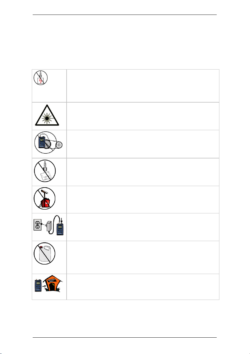
Precautions
Please read and understand this section before operating your
Spotcheck device. Heed all warnings and recommendations to prevent
data inaccuracy, damage to the instrument, or injury.
Do not attach sensors to any object with a high potential
voltage i.e. a voltage that exceeds 50 V DC or 32 V AC or
the ‘safety extra low voltage’ (SELV) defined by your local
power authority.
Do not stare directly into the laser pointer, or point the laser
at others. Doing so may cause permanent eyesight
damage.
Ensure the accelerometer cable cannot become entangled
with any rotating or moving machinery.
Do not bring any objects sensitive to magnetic fields near
the magnetic mounting bases (e.g. credit cards, floppy
disks, mechanical watches).
Do not operate the instrument in an explosive environment.
Use only an approved power adapter 4.2 V, 600 mA output,
center positive.
Use a mild detergent diluted in warm water to clean the
device. Do not use abrasive or polishing substances,
hydrocarbons, petrochemicals or solvents, as they will
degrade the plastic casing.
If the instrument malfunctions, return it to an authorized
dealer. Do not attempt to repair the instrument yourself as
this will void your warranty.
Spotcheck Instrument Reference Guide 5
Page 10

Section 1: Introduction
Instrument Input and Output Ports
The top panel of the instrument is equipped with the following Input and
Output ports:
Device Top Panel (I/O)
1. BNC sensor input
2. Charger power input socket (4.2 Volt, 600 mA input)
3. Non-contact infrared temperature sensor
4. Laser pointer
Spotcheck Instrument Reference Guide 6
Page 11

Section 1: Introduction
Front Panel
The table outlines the functions available on the front panel of the
Spotcheck device.
Instrument Front Panel
Function Description
Turns the instrument on and toggles selected values.
Activates the device's vibration measurement mode.
Holds or releases the current vibration reading on the LCD
screen. When taking Velocity measurements, pressing this
button will display an alarm value (see the
'Understanding ISO 10816-3 Vibration Alarms' section).
Activates the device's temperature sensor.
Enables/disables the laser pointer and holds/releases the
current temperature measurement on the LCD screen.
Activates the device's bearing measurement mode. When
taking a BG measurement, pressing this button will
display an alarm value (see the 'Understanding Bearing
Alarms' section).
Spotcheck Instrument Reference Guide 7
Page 12

Section 1: Introduction
Battery Pack
The Spotcheck device is powered by a removable, rechargeable LithiumIon 3 V, 1700 mA battery pack. Once fully charged, the battery pack will
allow the device to operate continuously for up to 48 hours.
The battery's current charge level is indicated by a battery icon in the
upper right-hand corner of the LCD screen.
Charge Battery Pack
Battery Level Indicator (Top Right)
To charge the battery pack:
1. Connect the AC power adapter included with the device to a
powered outlet (100-240 Volt, 50/60 Hz).
2. Connect the charger power output plug to the device's charger
input socket — The included DC in-car charger may be used to
charge the battery pack in a vehicle with a 12 V negative-chassis
power system.
3. Connect the in-car charger's DC output to the device's charger
power socket.
Bi-color LEDs on the battery chargers indicate the battery's charge state
when connected and powered: orange when the battery is charging and
green once the charge cycle has completed.
A full battery charge from empty will complete in approximately three
hours.
IMPORTANT! Use only the AC mains or DC in-car battery chargers
included in your Spotcheck device kit. Other chargers may damage
the device and/or battery pack and may void your warranty.
Charge the battery pack for two hours before or during your first use of
the device. Replacement battery packs are available from Commtest
Instruments.
Spotcheck Instrument Reference Guide 8
Page 13

Section 1: Introduction
Remove Battery Pack
To remove the battery pack:
1. Open the rear battery compartment by pressing the cover firmly
then sliding downward.
2. Set the battery cover aside and remove the battery from its
compartment.
3. Disconnect the power plug and socket (positive and negative are
indicated by color and the socket and plug can be connected in only
one direction).
Replacement batteries (part number SPOT0503) are available from
authorized Commtest Instruments distributors.
WARNING! Power should not be supplied to the device when
removing the battery. Unplug any connected charger before
proceeding.
WARNING! Damaged batteries should not be re-inserted into the
Spotcheck device.
WARNING! Dispose of damaged batteries responsibly and in
accordance with local regulations.
WARNING! Do not disassemble the battery pack or dispose of in
fire.
Spotcheck Instrument Reference Guide 9
Page 14

Section 2: Instrument Basics
Section 2: Instrument Basics
This section describes how to use the measurement and analysis
functions of your Spotcheck device. You will learn to:
• Power up the instrument and turn it off
• Attach the accelerometer sensor and stinger probe
• Take a vibration overall measurement
• Evaluate a vibration overall measurement alarm
• Take a bearing BG and BV vibration measurement
• Evaluate a bearing BG and BV alarm
• Take a temperature measurement
Power On/Off
To switch on your Spotcheck device, press and hold the SELECT key
for more than 1 second to power on the Spotcheck device.
To switch off you device, press and hold the SELECT key then press
either the BEARING key or the VIBRATION key to power off the
Spotcheck device.
NOTE: The Spotcheck device will power down automatically if no
keypad buttons are pressed for 3 minutes.
Spotcheck Instrument Reference Guide 10
Page 15

Section 2: Instrument Basics
Accelerometer Sensor
The accelerometer sensor is connected to the device via BNC, then
attached to the machinery being measured using the included magnetic
mount or a stud.
1. Attach the sensor cable plug to the BNC connector by inserting and
gently turning clockwise. Remove by turning in an anti-clockwise
direction then pulling away.
2. Screw the accelerometer in a clockwise direction onto the magnetic
3. If the measurement location is smaller than the magnetic base of
4. Remove the accelerometer sensor from the magnetic base by
5. Screw the stinger probe onto the end of the accelerometer in a
6. Press the tip of the stinger probe firmly against the surface being
WARNING! Do NOT remove the connector by pulling the sensor
cable. This may damage the cable. Always remove by gripping the
BNC connector then gently twisting in an anti-clockwise direction
for one quarter of a turn before pulling away.
base. Attach the base and sensor to the measurement point.
the accelerometer, use the included stinger probe.
unscrewing in an anti-clockwise direction.
clockwise direction.
measured.
Spotcheck Instrument Reference Guide 11
Stinger Probe
Page 16

Section 2: Instrument Basics
Sensor Guidelines
When attaching your accelerometer sensor using its magnetic base or a
stud, the following guidelines should be observed:
• Attach the accelerometer to a sturdy, rigidly mounted and non-
flexible structure, where vibration from the rotating part of the
machine will be accurately transmitted. Do not attach sensors
to sheet metal, guards, or any machine structure which is not
closely coupled to the source of vibration in the spinning rotor,
as the vibration of such a structure will be different to the
vibration source.
• The attachment structure must be at least 10 times heavier
than the accelerometer itself. Do not mount the accelerometer
on lightweight motors or similar parts as the weight of the
accelerometer will distort the vibration signal. Use the stinger
probe for small structures or small/inaccessible measurement
points.
• Attach the accelerometer as closely as possible to, and in line
with, the centerline of the bearings in order to avoid distorted
signals.
• The mounting surface should be flat and smooth where the
accelerometer makes contact. Attach the accelerometer using
the supplied magnetic accelerometer base or a threaded stud
on the machine surface. The accelerometer should not move
independently of the machine part it is attached to, nor should
the accelerometer cable.
• Ensure the accelerometer is oriented correctly as vibration can
differ greatly with respect to direction.
• If you are undertaking an ongoing study of a particular
measurement point, always attach the accelerometer at exactly
the same position used for previous measurements (mark the
position if necessary).
• Keep the accelerometer clear from other cables, ensuring it is
not twisted, kinked or tangled.
Spotcheck Instrument Reference Guide 12
Page 17

Section 2: Instrument Basics
Vibration Overall Measurements
The Spotcheck device measures broadband frequencies to generate a
machine's ‘overall’ summed vibration level. High overall vibration levels
are typically an indicator of unbalance, mechanical failure or wear.
If overall vibration measurements are taken at regular intervals (weekly,
for example) and noted, an historical trend of typical or ‘normal’ machine
vibration levels can be generated. This is called a ‘baseline’. When new
measurements are compared with this baseline value any significant
increases in the overall vibration level of the component can more easily
be identified.
As always, when determining the state of mechanical components you
must use common sense. In addition to measured vibration levels you
should visually inspect machinery for dirt, wear or movement; listen for
unusual mechanical noises and vibrations, and feel for temperature
changes.
NOTE: The Spotcheck device includes a temperature sensor that
can be used to identify temperature baseline values. These
temperature values can be used in conjunction with vibration
baselines to more effectively monitor machinery condition over
time. See the 'Take a Temperature Measurement' section for more
information.
Spotcheck Instrument Reference Guide 13
Page 18

Section 2: Instrument Basics
Displacement, Velocity, Acceleration
The Spotcheck device measures in displacement, velocity and
acceleration.
• Displacement is a measurement of the distance between two
points in mil (thousandth of an inch). In this case between the
resting position of the vibration sensor and its position of
maximum excursion during movement (caused by motion of the
machinery it is attached to).
• Velocity is a measurement of the rate of change of
displacement in inches per second, or the speed of the vibration
sensor in a particular direction. For example, if an object is
moving Northward, the velocity of the object in the North
direction is its speed, but its velocity in the East or West
direction is zero, and its velocity in the South direction is the
negative of its speed.
• Acceleration is a measurement of the rate of velocity change of
the vibration sensor around its rest location in g. That is, the rate
at which the sensor is gaining or losing speed in a particular
direction.
Spotcheck Instrument Reference Guide 14
Page 19

Section 2: Instrument Basics
Take Vibration Overall Measurement
The steps below assume that you have already successfully connected
and mounted the accelerometer sensor (or are holding the stinger probe
tip against the machinery surface).
1. Press and hold the SELECT key for 1 second to power on the
Spotcheck device — The velocity measurement type will be selected
('Vel' will be displayed in the LCD screen's top left-hand corner). A
vibration measurement numeric value will be shown in the center of
the screen.
NOTE: If the sensor has not been connected to the device, or if a
sensor fault is detected, the device will display a sensor query icon
on the LCD screen.
Sensor Alert Icon
2. Press the SELECT key repeatedly to toggle between the device's
available measurement types: 'Vel' (velocity in ips RMS), 'Disp'
(displacement in mil peak-to-peak) and 'Acc' (acceleration in g peak).
3. Press the VIBRATION key to hold the value being shown
onscreen, and again to return to the active measurement mode.
Spotcheck Instrument Reference Guide 15
Page 20

Section 2: Instrument Basics
Tips for Taking Measurements
Here are some tips for taking measurements:
• You should always take measurements using the machine
operating mode that is typical for that machine (using a typical
load and running speed). This will ensure that the loads on the
components, such as bearings, are the same as those that
define their wear. For multi-operating mode machines it is best
to take measurements when the loads on the bearings are at a
maximum and to take all future measurements in the same
mode.
• When taking the measurement, try not to lean on the machine
and do not put heavy objects (e.g. heavy tool boxes) on it since
this will change the vibratory behavior of the machine.
• If there are machines operating nearby that might affect the
vibration of the machine you are measuring, stop those
surrounding machines if possible.
• In addition to the measurements that you will be taking, if
possible, stop and listen to the sound of the machine; look for
loose bolts and oil leaks; take note of any machine parts that
are vibrating visibly; feel for hot bearings and manually ‘feel’ the
vibration (e.g. with a screwdriver) to look for symptoms that
might later aid vibration analysis. This should be done only if it is
safe to do so.
• If you have a stroboscope you may wish to use it to ‘freeze’
rotating shafts, belts, couplings etc. to observe their operating
shapes and relative speeds.
Spotcheck Instrument Reference Guide 16
Page 21

Section 2: Instrument Basics
ISO 10816-3 Vibration Alarms
If a velocity measurement is taken and the VIBRATION key is then
pressed, the measured value will be retained on the LCD screen (placed
on 'hold'). A vibration alarm level using the ISO 10816-3:2009 standard
will also be displayed on the LCD screen. Three alarm levels are possible
and may be shown:
• OK (indicated by a tick icon)
• Alert (indicated by a single bell icon)
• Danger (indicated by two bell icons)
The alarm level displayed is only applicable to the machine group
(determined by the machinery's size and power) and support class
(determined by the support structure the machinery has been mounted
to: rigid, or flexible) specified in the bottom left-hand corner of the
screen.
You must manually cycle through the four machine group and support
class options available. Press the SELECT key repeatedly until the
machine and support type combination most appropriate for the
machinery being measured is displayed.
The four available combinations are:
• ISO 1 & 3 - R
• ISO 1 & 3 - F
• ISO 2 & 4 - R
• ISO 2 & 4 - F
The first two numbers indicate the machine group applicable to the
alarm, and the last letter the support class.
Spotcheck Instrument Reference Guide 17
Page 22

Section 2: Instrument Basics
Machine Groups
The following machine groups are available:
• Group 1. These are large machines with rated power output
above 300 kW and shaft diameters greater than or equal to 315
mm. These machines are typically equipped with sleeve
bearings and operate at speeds between 120 RPM and 15 000
RPM.
• Group 2. These are medium sized machines with rated power
output between 15 kW and 300 kW and shaft diameters of
between 160 mm and 315 mm. These machines are typically
equipped with element bearings and operate at speeds greater
than 600 RPM.
• Group 3. Pumps with multi-vane impellers and separate drive
motors (centrifugal, mixed flow or axial flow) with rated power
above 15 kW.
• Group 4. Pumps with multi-vane impellers with integrated drive
motors (centrifugal, mixed flow or axial flow) with rated power
Support Class
above 15 kW.
The following support classes are available:
• R (Rigid). Appropriate for machinery mounted on rigid
mountings, such as steel or concrete.
• F (Flexible). Appropriate for machinery mounted on flexible
mountings, such as rubber or springs.
NOTE: A quick reference list of these values is printed on the
device's rear label. For more information on machine groups and
support classes, see the 'ISO 10816-3 Machine Groups Overview'
section and the 'ISO 10816-3 Support Classes Overview' section.
Using a combination of the vibration level, the machine group and the
support class, alarms are generated as follows:
Spotcheck Instrument Reference Guide 18
Page 23

Section 2: Instrument Basics
Check Status of Bearing
The steps below assume you have already successfully connected and
mounted the accelerometer sensor (or are holding the stinger probe tip
against the machinery surface).
1. Press and hold the SELECT key for 1 second to power on the
Spotcheck device.
2. Press the BEARING key. The BG measurement type will be
selected ('Bg' will be displayed in the LCD screen's top left-hand
corner). A vibration measurement numeric value will be shown in the
center of the screen.
3. Press the SELECT key to toggle between the device's two
4. Press the BEARING key to hold the value being shown onscreen,
NOTE: If the sensor has not been connected to the device, or if a
sensor fault is detected, the device will display a sensor query icon
on the LCD screen.
Sensor Alert Icon
available bearing measurement types: 'Bg' (acceleration in g RMS),
'Bv' (velocity in ips RMS).
and again to return to the active measurement mode.
Spotcheck Instrument Reference Guide 19
Page 24

Section 2: Instrument Basics
Bearing Alarms
If a bearing vibration measurement is taken and the BEARING key is
then pressed, the measured value will be retained on the LCD screen
(placed on 'hold'). A vibration alarm level will also be displayed on the
LCD screen. Three alarm levels are possible and may be shown:
• OK (indicated by a tick icon)
• Alert (indicated by a single bell icon)
• Danger (indicated by two bell icons)
Bearing alarm values displayed by the Spotcheck device are based on
'rule of thumb' tables and should therefore be used as simple indicators
of potential problems. They should not be used as the sole determinant
of a component's condition.
Acceleration Alarms (BG)
When taking a BG (bearing acceleration) reading, the alarm level
displayed by pressing the BEARING key is only applicable to the
bearing shaft speed specified in the bottom left-hand corner of the LCD
screen.
You must manually cycle through the five bearing shaft speed options
available. Press the SELECT key repeatedly until the shaft speed
most appropriate for the machinery being measured is displayed.
The five available shaft speeds are:
• RPM:<500. Suitable for shafts rotating at below 500 RPM.
• RPM:<1000. Suitable for shafts rotating at between 500 RPM
and 1000 RPM.
• RPM:<2000. Suitable for shafts rotating at between 1000 RPM
and 2000 RPM.
• RPM:<5000. Suitable for shafts rotating at between 2000 RPM
and 5000 RPM.
• RPM:<10000. Suitable for shafts rotating at between 5000 RPM
Spotcheck Instrument Reference Guide 20
and 10 000 RPM.
Page 25

Section 2: Instrument Basics
BG alarms are based on acceleration readings taken between 1 kHz and
12 kHz. These are the frequencies in which bearing failures are typically
most easily detected. The alarms are generated using the following
vibration level against shaft speed matrix:
Velocity Alarms (BV)
BV alarms are based on velocity readings in ips RMS taken between 1
kHz and 12 kHz. Like BG alarms, BV alarms are based on established
'rule of thumb' measurement levels that have traditionally given reliable
indications of a bearing's condition with up to 90% accuracy.
These alarms are generated using the following vibration levels:
• OK. Bearing velocity levels of less than 0.04 ips RMS suggesting
correctly greased bearings operating normally.
• Warning. Bearing velocity levels of between 0.04 ips RMS and
0.08 ips RMS indicating the existence of internal surface wear
that may not be detectable by the human eye, actual bearing
damage or poorly/ungreased bearings.
• Danger. Bearing velocity levels above 0.08 ips RMS suggesting
Spotcheck Instrument Reference Guide 21
that a bearing failure may occur imminently.
Page 26

Section 2: Instrument Basics
Take Temperature Measurement
Heat is a strong indicator of a failing component or unbalance. Bearing
heat is typically generated by friction between surfaces resulting from
damage or poor lubrication. As surface contact increases, temperatures
will rise until a bearing failure occurs.
By regularly monitoring and noting the temperature of a rotating
component it becomes possible to ‘trend’ its temperature over time and
identify when the component may require attention (as indicated by an
unusual increase in temperature).
If comparing the casing temperatures of several identical components
(such as bearings or drives) under identical loads it is also possible to
identify components that are notably warmer than their companions,
suggesting mechanical deterioration.
NOTE: If establishing a temperature trend it is important that the
same physical location is sampled each time a measurement is
taken, and that measurements are taken from the same distance.
WARNING! The Spotcheck device's laser pointer will energize
automatically when measuring temperatures. Direct the laser lens
away from yourself and others in the vicinity before proceeding
with the steps below. Ensure you are familiar with the laser safety
guidelines described in the 'Laser Safety' section.
Spotcheck Instrument Reference Guide 22
Page 27

Section 2: Instrument Basics
To take a temperature measurement:
1. Press and hold the SELECT key for 1 second to power on the
Spotcheck device.
2. Press the TEMPERATURE key. The temperature measurement
mode will be selected ('Temp' will be displayed in the screen's top
left-hand corner). A temperature measurement numeric value will
be shown in the center of the LCD screen. This is the temperature in
front of the device's IR temperature sensor. Ambient temperature
will be displayed in the bottom left-hand corner and the
measurement unit in the bottom right-hand corner.
NOTE: The default temperature unit is degrees Celsius. To change
to Fahrenheit, press the SELECT key.
3. Point the laser guide at the surface to be measured. The laser
provides a visual indication of the field of view of the infrared
thermometer sensor. Ensure the surface is within the device's 2
meter (6.5 foot) effective range. The LCD screen will display the
surface temperature of the target surface.
NOTE: The temperature range supported by the IR sensor is -20 °C
to 120 °C (-4 °F to 248 °F).
4. Press the TEMPERATURE key to hold the value being shown
onscreen, and again to return to the active measurement mode.
Pressing this key will also disable and re-energize the laser pointer.
Accurate temperature measurement using an IR sensor depends largely
on the size of the target and the distance between the target and the
thermal sensor. IR detectors have a circular, conical field of view: small
and narrow directly in front of the sensor and gradually spreading wider
as the distance between the sensor and the target increases.
For this reason it is important that you consider the distance between
the Spotcheck device and the equipment being measured. At a distance
of 250 mm or 10 inches the sensor's field of field is a small circle with a
diameter of approximately 31.25 mm (1.2 inches). This is suitable for
many smaller bearings. However, at a distance of 2000 mm or 79 inches
(the device's maximum range) the field of view is a much larger 250 mm
(9.8 inches) in diameter.
Spotcheck Instrument Reference Guide 23
Page 28

Section 2: Instrument Basics
NOTE: For maximum accuracy, the IR sensor should include only
the target surface in its field of view. For this reason
measurements of smaller objects should, if possible, be taken at
close range. Beyond 2 meters or 6.5 feet temperature readings of
even large targets may become unreliable.
Spotcheck Instrument Reference Guide 24
Page 29

Section 2: Instrument Basics
Laser Safety
When using the Spotcheck device's laser pointer, please observe the
following laser safety guidelines:
• Never point the laser beam at a person. The laser pointer is
designed to target inanimate objects.
• Laser pointers are not toys. Keep out of reach of minors and
children.
• Do not look into the laser beam or view directly with optical
instruments. Eye damage may result.
• Do not direct the laser pointer at reflective surfaces. Reflected
beams can act like direct beams.
Spotcheck Instrument Reference Guide 25
Page 30

Section 3: Supplemental Reading
Section 3: Supplemental Reading
This section discusses suitable machine groups and support classes for
the ISO 10816-3 standard and the significance of a machine's support
structure. Additionally, this section includes a primer on assessing roller
bearing states using vibration measurements.
ISO 10816-3 Machine Groups Overview
The ISO 10816-3 standard encompasses a broad range of industrial
plant machinery with nominal power above 15 kW and nominal speeds
of between 120 RPM and 15 000 RPM when measured in situ. Machinery
that this standard applies to includes:
• Steam turbines with nominal power of less than 50 MW
• Steam turbines with nominal power above 50 MW and speeds
of less than 1500 RPM or over 3600 RPM (excluding machines
included in ISO 10816-2)
• Rotating compressors
• Industrial gas turbines with nominal power of less than 3 MW
• Centrifugal, mix flow, or axial flow pumps
• Electric generators, excluding hydroelectric generators and
pump stations
• Electric motors of all types
• Blowers and fans
Spotcheck Instrument Reference Guide 26
Page 31

Section 3: Supplemental Reading
ISO 10816-3 Support Classes Overview
The ISO 10816-3 standard classifies machinery according to its
mounting style, whether flexible or rigid. This is done as mounting type
typically reflects the location of the machinery's rigid-structure
resonances relative to basic machine running speed.
For example, a machine supported by flexible rubber mounts or a spring
will typically have resonances at lower running speeds. Vibrations may
be stronger at lower speeds, reducing as the machinery reaches its
operating speed. This type of machine is regarded as flexible by the ISO
standard.
Machinery mounted on flexible supports will also typically vibrate more
during run-up and coast-down.
Modern machines often operate at high speeds and are equipped with
flexible bearing supports and foundations. These can be treated as
flexible even when not mounted on rubber or springs.
Although the ISO 10816-3 standard allows for slightly higher vibration
limits when a machine's support is considered flexible rather than rigid,
resonant conditions (even at operating speeds) are regarded as
abnormal.
Spotcheck Instrument Reference Guide 27
Page 32

Section 3: Supplemental Reading
Assess Bearing State
When the rolling elements inside a bearing move, broadband noise and
vibration is generated. Noise and vibration levels will increase if the
bearing is not correctly greased, is overloaded (due to, for example,
misalignment) or has a damaged surface.
As the vibrations generated by bearing wear and damage are
broadband (that is, they cover a wide range of frequencies), any
frequency could be regarded as suitable for measurement. However, if
the chosen frequency band also contains low frequencies (below 1 kHz)
the measurement will not consist only of bearing frequencies. The
bearing condition may thereby become harder to interpret.
If the chosen frequency band contains only bearing frequencies the
bearing condition assessment will be more accurate. For this reason the
Spotcheck device measures only frequencies above 1 kHz when in its
bearing measurement mode.
High bearing readings can also be found in gearboxes and other
machines where steel meets steel and no bearing faults exist. The
reason for this is that these components naturally produce frequencies
in the same range as bearing faults.
Bearings should not typically be replaced only on the basis of a bearing
value displayed by the Spotcheck device. A high bearing vibration value
is merely an indicator that further analysis is required. Further analysis
will determine whether the elevated levels at specific frequencies
correspond with mathematically calculated bearing frequencies. More
advanced tools such as the vb7 and vb8 data analyzers, when used in
conjunction with the Ascent software, are ideal for this application.
Bearing condition values are influenced by bearing lubrication. If a high
value is displayed, the bearing should in the first instance be re-greased.
After greasing the bearing condition value will typically decrease.
However, if there is mechanical damage the value will quickly rise again.
Spotcheck Instrument Reference Guide 28
Page 33

Section 3: Supplemental Reading
Appendix: Spotcheck Specifications
The table lists the technical specifications for your Spotcheck device.
Specifications Spotcheck Device Remarks
Sensors
Sensor input 1 channel BNC
Sensor Accelerometer 100 mV/g IEPE/ICP© type. Top exit.
Vibration Acceleration 0 to 20 g Peak, 10 Hz to 12 kHz
Velocity 0 to 200 mm/s RMS, 10 Hz to 1000 Hz
Displacement 0 to 2000 µm Pk-Pk, 10 Hz to 1000 Hz
BG 0 to 20 g RMS, 1000 Hz to 12 kHz
BV 0 to 200 mm/s RMS, 1000 Hz to 12 kHz
Measurement Features
Accuracy ± 5%
Alarms Automatic Velocity Alarm Check
Automatic Bearing Alarm Check
Temperature -20 °C to 120 °C (-4 °F to 248 °F) Accuracy ± 2 °C. Built in IR sensor
Display & Communication
Display Monochromatic LCD LED backlit
Resolution 128 x 64 pixels
Viewing area 30 mm x 16 mm (1.2” x 0.6”)
Integrated 80 cm cable.
ISO 10816-3
BG and BV (proprietary)
with laser pointer
Spotcheck Instrument Reference Guide 29
Page 34

Section 3: Supplemental Reading
116 mm x 78 mm x 24 mm (4.6" x 3" x 0.9")
230 g (0.5 lb)
Laser
Type Compact laser diode Red
Frequency 650 nm
Class 2 IEC60825-
Power 1 mW (max)
Battery &
Charger
Battery type Custom Lithium Ion pack 3.6 V, 1700 mAh Rechargeable, user-replaceable
Operating time >48 hours
Charger type Internal charging, automatic control External Power pack 12 V DC, 3 A
Charge rate 600 mA nominal
Charge time 3 hours For complete charge
Mechanical
Size
Weight
Environment
Operating temp -10 °C to 50 °C (14 °F to 122 °F) Non-condensing atmosphere only
Storage
temperature
-20 °C to 60 °C (-4 °F to 140 °F)
1:1993+A1:1997+A2:2001
compliant
output, included in kit
128 mm (5") including BNC
connector
Including battery, sensor and cable
Sealing IP64 Dust tight, splashed water
Certification CE
Spotcheck Instrument Reference Guide 30
Page 35

Section 3: Supplemental Reading
Servicing and Maintenance
Servicing is not required to keep the Spotcheck device in proper
operating condition. In the event of a malfunction, the device should be
returned to GE Measurement & Control, New Zealand for inspection and
repair.
Do NOT open or disassemble. No user-serviceable parts.
Spotcheck Instrument Reference Guide 31
Page 36

Index
A
Acceleration • 14
Alarms
Vibration • 28
Appendix
Specifications • 29
Assessing Bearing State • 28
B
Battery • 8, 9
Bearings • 19, 28
C
Charging the Battery Pack • 8
Check the Status of a Bearing •
19
D
Displacement • 14
Displacement, Velocity and
Acceleration • 14
F
Front Panel • 7
I
Instrument I/O • 6
ISO 10816-3 • 26, 27
ISO 10816-3 Machine Groups
Overview • 18, 26
ISO 10816-3 Support Classes
Overview • 27
L
Laser
Safety • 1, 5, 22, 25
Laser Safety • 22, 25
P
Power • 10
Powering On/Off • 10
Precautions • 5
Product Overview • 2
R
Removing the Battery Pack • 9
S
Section 1
Introduction • 1
Section 2
Instrument Basics • 10
Section 3
Supplemental Reading • 26
Sensor Guidelines • 12
Servicing and Maintenance • 31
Standard Features • 3
Standard Kit Items • 4
T
Take a Temperature
Measurement • 13, 22
Take a Vibration Overall
Measurement • 15
The Battery Pack • 8
Tips for Taking Measurements •
16
U
Understanding Bearing Alarms
• 7, 20
Understanding ISO 10816-3
Vibration Alarms • 3, 7, 17
Using the Accelerometer Sensor
• 11
Using Vibration Overall
Measurements • 13
Spotcheck Instrument Reference Guide 32
Page 37

V
Velocity • 14
Vibration Overalls • 15
Spotcheck Instrument Reference Guide 33
 Loading...