

Page 1
Case Mounted Accelerometers
Datasheet
Bently Nevada Machinery Condition Monitoring
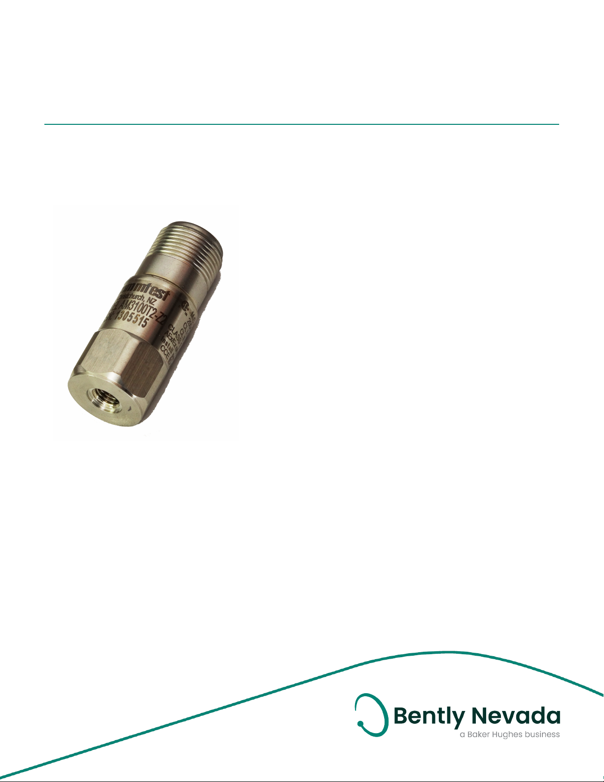
Description
The accelerometers in this sensor series offer a number of
features making them well suited for harsh industrial
environments and installation in locations with limited
available space.
These case-mounted accelerometers provide acceleration
measurements in units of g or m/s^2. The sensor has a
standardized output voltage proportional to the level of
acceleration which can interface to a variety of condition
monitoring solutions. The range of vibration frequencies
detected by these sensors spans from 0.2 – 14,000 Hz.
Features
l Rugged stainless design, corrosion resistant
l Hermetic seal, case isolated
l ESD protection
l Reverse wiring protection
l EMI / RFI shielded
l Hazardous area certifications
124M2609 Rev. C
Benefits
l Able to fit in small spaces
l Light weight for walk around programs
l Cross wiring will not harm sensor
l Prevents ground loops in permanent mount applications
l Can be hosed down or submersed with proper connector
l Can be used in applicable certified hazardous areas
Compliance
l See individual accelerometers for compliance.
Page 2

Case Mounted Accelerometers
Datasheet 124M2609 Rev. C
Ordering
Information
Accelerometer Part Number
AM3100T2-Z2
AS3100S2-Z2
AP3500S2-Z1
AP3500T2-Z1
AS3100S2-Z0
AM3100T2-Z0
Top exit sensor, 100 mV/g, Zone 2
rated
Side exit sensor, 100 mV/g, Zone 2
rated
Side exit sensor, 500 mV/g, Zone 1
rated
Top exit sensor, 500 mV/g, Zone 1
rated
Side exit sensor, 100 mV/g, Zone 0
rated
Top exit sensor, 100 mV/g, Zone 0
rated
Accessories supplied:
l 1/4-28 to 1/4-28 mounting stud
l calibration data
2/18
Page 3
Case Mounted Accelerometers
Datasheet 124M2609 Rev. C
AM3100T2-Z2
Specifications
Dynamic
Sensitivity, ± 5% @25°C 100 mV/g
Acceleration range 80 g peak
Amplitude nonlinearity 1%
±10%: 0.7-9,000 Hz
Frequency response
Resonant frequency 30 kHz
Transverse sensitivity, max ±5% of axial
Temperature response
Electrical
Voltage source 18-30 Vdc
Current regulating diode 2-10 mA
Broadband electrical noise @
2.5 Hz to 25 kHz
Spectral electrical noise @ 10 Hz 7 μg/√Hz
Spectral electrical noise @ 100 Hz
Spectral electrical noise @ 1000
Hz
Output Impedance, max 100 Ω
Bias output voltage 12 Vdc
Grounding
± 3 dB: 0.4-14,000
Hz
-55°C : -20%
+120°C : +10%
500 μg
4 μg/√Hz
2 μg/√Hz
case isolated,
internally shielded
Physical
Sensing element design
Weight 62 grams
Case material 316L Stainless Steel
Mounting
Connector
Recommended cabling
PZT ceramic /
shear
71/4-28 UNF
tapped hole
2-pin, MIL-C-5015
style
Shielded, twisted
pair, no longer
than 100 feet
Connections
Connector Pin Function
Shell ground
A power/signal
B common
Frequency response and spectral noise
values are typical.
Environmental
Temperature range -55°C to 120°C
Vibration limit 500 g peak
Shock limit 5,000 g peak
Electromagnetic sensitivity,
equiv g, max
Sealing hermetic base strain
sensitivity, max
70 μg/gauss
0.0002 g/μstrain
3/18
Page 4

Case Mounted Accelerometers
Datasheet 124M2609 Rev. C
Compliance and Certifications
This device complies with part 15 of the FCC
Rules. Operation is subject to the following
conditions: (1) This device may not cause
harmful interference, and (2) This device must
accept any interference received, including
interference that may cause undesired
operation.
European Community Directives
ATEX Directive 2014/34/EU
EMC Directive 2014/30/EU
LV Directive 2014/35/EU
Reach Directive 1907/2006/EC
ROHS Directive 2011/65/EU
Standards
EN 61326-1
EN 60079-0
EN 60079-15
EN60079-11
Hazardous Area Approvals
CSA/NRTL/C
Class I, Div 2, Groups A, B, C, D
Class I, Zone 2, AEx/Ex na II T4
Install per drawing 117M2767
4/18
Page 5
Case Mounted Accelerometers
Datasheet 124M2609 Rev. C
Physical
AS3100S2-Z0
Specifications
Dynamic
Sensitivity, ± 5% @25°C 100 mV/g
Acceleration range 80 g peak
Amplitude nonlinearity 1%
±10% : 1.0-5,000 Hz
Frequency response
Resonant frequency 22 kHz
Transverse sensitivity, max ±5% of axial
Temperature response
Electrical
Voltage source 18-30 Vdc
Current regulating diode 2-10 mA
Broadband electrical noise @
2.5 Hz to 25 kHz
Spectral electrical noise @ 10 Hz 10 μg/√Hz
Spectral electrical noise @ 100 Hz
Spectral electrical noise @ 1000
Hz
Output Impedance, max 100 Ω
Bias output voltage 12 Vdc
Grounding
± 3 dB : 0.7-10,000
Hz
-55°C: -8%
+120°C: +10%
700 μg
5 μg/√Hz
5 μg/√Hz
Case isolated,
internally shielded
Sensing element design
Weight 145 grams
Case material 316L Stainless Steel
Mounting
Connector
Recommended cabling
PZT ceramic /
shear
1/4-28 captive
hex head ascrew
2-pin, MIL-C-5015
style
Shielded, twisted
pair, no longer
than 100 feet
Connections
Connector Pin Function
Shell ground
A power/signal
B common
Frequency response and spectral noise
values are typical.
Environmental
Temperature range -50°C to 120°C
Vibration limit 500 g peak
Shock limit 5,000 g peak
Electromagnetic sensitivity,
equiv g, max
Sealing hermetic base strain
sensitivity, max
70 μg/gauss
0.0002 g/μstrain
5/18
Page 6

Case Mounted Accelerometers
Datasheet 124M2609 Rev. C
Compliance and Certifications
1. This device may not cause harmful
interference.
2. This device must accept any interference
received, including interference that may
cause undesired operation.
European Community Directives
ATEX Directive 2014/34/EU
EMC Directive 2014/30/EU
LV Directive 2014/35/EU
Reach Directive 1907/2006/EC
ROHS Directive 2011/65/EU
Standards
EN 61326-1
EN 60079-0
EN 60079-15
EN60079-11
Hazardous Area Approvals
CSA/NRTL/C
Class I, Div 1, Groups A, B, C, D
Class II, Div 1, Groups E, F, G
Class III, Div 1
Class I, Zone 0, Ex ia IIC T4
Class I, Zone 0, AEx ia IIC T4
ATEX
Ga Ex ia IIC T4
Install per drawing 117M4394
6/18
Page 7

Case Mounted Accelerometers
Datasheet 124M2609 Rev. C
Physical
AP3500S2-Z1
Specifications
Dynamic
Sensitivity, ± 5% @25°C 500 mV/g
Acceleration range 80 g peak
Amplitude nonlinearity 1%
±10% : 0.4-1,500 Hz
Frequency response
Resonant frequency 18 kHz
Transverse sensitivity, max ±7% of axial
Temperature response
Electrical
Voltage source 18-30 Vdc
Current regulating diode 2-10 mA
Broadband electrical noise @
2.5 Hz to 25 kHz
Spectral electrical noise @ 10 Hz 2 μg/√Hz
Spectral electrical noise @ 100 Hz
Spectral electrical noise @ 1000
Hz
Output Impedance, max 100 Ω
Bias output voltage 10 Vdc
Grounding
± 3 dB : 0.2-3,700
Hz
-55°C: -8%
+120°C: +5%
12 μg
0.6 μg/√Hz
0.2 μg/√Hz
case isolated,
internally shielded
Sensing element design
Weight 148 grams
Case material 316L Stainless Steel
Mounting
Connector
Recommended cabling
PZT ceramic /
shear
1/4-28 captive
hex head screw
2-pin, MIL-C-5015
style
shielded, twisted
pair, no longer
than 100 feet
Connections
Connector Pin Function
Shell ground
A power/signal
B common
Frequency response and spectral noise
values are typical.
Environmental
Temperature range -50°C to 120°C
Vibration limit 250 g peak
Shock limit 2,500 g peak
Electromagnetic sensitivity,
equiv g, max
Sealing hermetic base strain
sensitivity, max
5 μg/gauss
0.001 g/μstrain
7/18
Page 8

Case Mounted Accelerometers
Datasheet 124M2609 Rev. C
Compliance and Certifications
1. This device may not cause harmful
interference.
2. This device must accept any interference
received, including interference that may
cause undesired operation.
European Community Directives
ATEX Directive 2014/34/EU
EMC Directive 2014/30/EU
LV Directive 2014/35/EU
Reach Directive 1907/2006/EC
ROHS Directive 2011/65/EU
Standards
EN 61326-1
EN 60079-0
EN 60079-15
EN60079-11
Hazardous Area Approvals
CSA/NRTL/C
Class I, Div 1, Groups A, B, C, D
Class I, Zone 1: Ex ia IIC T4
Install per drawing 117M4393
8/18
Page 9

Case Mounted Accelerometers
Datasheet 124M2609 Rev. C
Physical
AS3100S2-Z0
Specifications
Dynamic
Sensitivity, ± 5% @25°C 100 mV/g
Acceleration range 80 g peak
Amplitude nonlinearity 1%
±10% : 1.0-5,000 Hz
Frequency response
Resonant frequency 22 kHz
Transverse sensitivity, max ±5% of axial
Temperature response
Electrical
Voltage source 18-30 Vdc
Current regulating diode 2-10 mA
Broadband electrical noise @
2.5 Hz to 25 kHz
Spectral electrical noise @ 10 Hz 10 μg/√Hz
Spectral electrical noise @ 100 Hz
Spectral electrical noise @ 1000
Hz
Output Impedance, max 100 Ω
Bias output voltage 12 Vdc
Grounding
± 3 dB : 0.7-10,000
Hz
-55°C: -8%
+120°C: +10%
700 μg
5 μg/√Hz
5 μg/√Hz
Case isolated,
internally shielded
Sensing element design
Weight 145 grams
Case material 316L Stainless Steel
Mounting
Connector
Recommended cabling
PZT ceramic /
shear
1/4-28 captive
hex head ascrew
2-pin, MIL-C-5015
style
Shielded, twisted
pair, no longer
than 100 feet
Connections
Connector Pin Function
Shell ground
A power/signal
B common
Frequency response and spectral noise
values are typical.
Environmental
Temperature range -50°C to 120°C
Vibration limit 500 g peak
Shock limit 5,000 g peak
Electromagnetic sensitivity,
equiv g, max
Sealing hermetic base strain
sensitivity, max
70 μg/gauss
0.0002 g/μstrain
9/18
Page 10

Case Mounted Accelerometers
Datasheet 124M2609 Rev. C
Compliance and Certifications
1. This device may not cause harmful
interference.
2. This device must accept any interference
received, including interference that may
cause undesired operation.
European Community Directives
ATEX Directive 2014/34/EU
EMC Directive 2014/30/EU
LV Directive 2014/35/EU
Reach Directive 1907/2006/EC
ROHS Directive 2011/65/EU
Standards
EN 61326-1
EN 60079-0
EN 60079-15
EN60079-11
Hazardous Area Approvals
CSA/NRTL/C
Class I, Div 1, Groups A, B, C, D
Class II, Div 1, Groups E, F, G
Class III, Div 1
Class I, Zone 0, Ex ia IIC T4
Class I, Zone 0, AEx ia IIC T4
ATEX
Ga Ex ia IIC T4
Install per drawing 117M4394
10/18
Page 11

Case Mounted Accelerometers
Datasheet 124M2609 Rev. C
Physical
AP3500T2-Z1
Specifications
Dynamic
Sensitivity, ± 5% @25°C 500 mV/g
Acceleration range 10 g peak
Amplitude nonlinearity 1%
±10% : 0.4-1,000 Hz
Frequency response
Resonant frequency 15 kHz
Transverse sensitivity, max ±5% of axial
Temperature response
Electrical
Voltage source 18-30 Vdc
Current regulating diode 2-10 mA
Broadband electrical noise @
2.5 Hz to 25 kHz
Spectral electrical noise @ 10 Hz 2 μg/√Hz
Spectral electrical noise @ 100 Hz
Spectral electrical noise @ 1000
Hz
Output Impedance, max 100 Ω
Bias output voltage 10 Vdc
Grounding
± 3 dB : 0.2-2,300
Hz
-55°C: -8%
+120°C: +10%
8 μg
0.4 μg/√Hz
0.2 μg/√Hz
case isolated,
internally shielded
Sensing element design
Weight 142 grams
Case material 316L Stainless Steel
Mounting
Connector
Recommended cabling
PZT ceramic /
shear
1/4-28 UNF
tapped hole
2-pin, MIL-C-5015
style
shielded, twisted
pair, no longer
than 100 feet
Connections
Connector Pin Function
Shell ground
A power/signal
B common
Frequency response and spectral noise
values are typical.
Environmental
Temperature range -50°C to 120°C
Vibration limit 250 g peak
Shock limit 5,000 g peak
Electromagnetic sensitivity,
equiv g, max
Sealing hermetic base strain
sensitivity, max
20 μg/gauss
0.0001 g/μstrain
11/18
Page 12

Case Mounted Accelerometers
Datasheet 124M2609 Rev. C
Compliance and Certifications
This device complies with part 15 of the FCC
Rules. Operation is subject to the following
conditions: (1) This device may not cause
harmful interference, and (2) This device must
accept any interference received, including
interference that may cause undesired
operation.
European Community Directives
ATEX Directive 2014/34/EU
EMC Directive 2014/30/EU
LV Directive 2014/35/EU
Reach Directive 1907/2006/EC
ROHS Directive 2011/65/EU
Standards
EN 61326-1
EN 60079-0
EN 60079-15
EN60079-11
Hazardous Area Approvals
CSA/NRTL/C
Class I, Div 1, Groups A, B, C, D
Class I, Zone 1, Ex ia IIC T4
Install per drawing 117M4393
12/18
Page 13

Case Mounted Accelerometers
Datasheet 124M2609 Rev. C
Physical
AS3100S2-Z2
Specifications
Dynamic
Sensitivity, ± 5% @25°C 100 mV/g
Acceleration range 80 g peak
Amplitude nonlinearity 1%
±10%: 1.0-5,000 Hz
Frequency response
Resonant frequency 22 kHz
Transverse sensitivity, max ±5% of axial
Temperature response
Electrical
Voltage source 18-30 Vdc
Current regulating diode 2-10 mA
Broadband electrical noise @
2.5 Hz to 25 kHz
Spectral electrical noise @ 10 Hz 10 μg/√Hz
Spectral electrical noise @ 100 Hz
Spectral electrical noise @ 1000
Hz
Output Impedance, max 100 Ω
Bias output voltage 12 Vdc
Grounding
± 3 dB: 0.5-10,000
Hz
-55°C: -20%
+120°C: +10%
700 μg
5 μg/√Hz
5 μg/√Hz
case isolated,
internally shielded
Sensing element design
Weight 62 grams
Case material 316L Stainless Steel
Mounting
Connector
Recommended cabling
PZT ceramic /
shear
1/4-28 UNF
tapped hole
2-pin, MIL-C-5015
style
Shielded, twisted
pair, no longer
than 100 feet
Connections
Connector Pin Function
Shell ground
A power/signal
B common
Frequency response and spectral noise
values are typical.
Environmental
Temperature range -55°C to 120°C
Vibration limit 500 g peak
Shock limit 5,000 g peak
Electromagnetic sensitivity,
equiv g, max
Sealing hermetic base strain
sensitivity, max
70 μg/gauss
0.0002 g/μstrain
13/18
Page 14

Case Mounted Accelerometers
Datasheet 124M2609 Rev. C
Compliance and Certifications
1. This device may not cause harmful
interference.
2. This device must accept any interference
received, including interference that may
cause undesired operation.
European Community Directives
ATEX Directive 2014/34/EU
EMC Directive 2014/30/EU
LV Directive 2014/35/EU
Reach Directive 1907/2006/EC
ROHS Directive 2011/65/EU
Standards
EN 61326-1
EN 60079-0
EN 60079-15
EN60079-11:2011
Hazardous Area Approvals
CSA/NRTL/C
Class I, Div 1, Groups A, B, C, D
Class I, Zone 2: AEx/Ex na II T4
Install per drawing 117M2767
14/18
Page 15

Case Mounted Accelerometers
Datasheet 124M2609 Rev. C
Graphs and Figures
Figure 1: AM3100T2-Z2 dimensions
Figure 2: AS3100S2-Z0 dimensions
15/18
Page 16

Case Mounted Accelerometers
Datasheet 124M2609 Rev. C
Figure 3: AM3100T2-Z0 dimensions
Figure 4: AP3500S2-Z1 dimensions
16/18
Page 17

Case Mounted Accelerometers
Datasheet 124M2609 Rev. C
Figure 5: AP3500T2-Z1 dimensions
Figure 6: AS3100S2-Z2 dimensions
17/18
Page 18

Case Mounted Accelerometers
Datasheet 124M2609 Rev. C
Copyright 2019 Baker Hughes Company. All rights reserved.
Bently Nevada and Orbit Logo are registered trademarks of Bently Nevada, a Baker Hughes Business, in the United
States and other countries. The Baker Hughes logo is a trademark of Baker Hughes Company. All other product and
company names are trademarks of their respective holders. Use of the trademarks does not imply any affiliation
with or endorsement by the respective holders.
Baker Hughes provides this information on an “as is” basis for general information purposes. Baker Hughes does not
make any representation as to the accuracy or completeness of the information and makes no warranties of any
kind, specific, implied or oral, to the fullest extent permissible by law, including those of merchantability and fitness
for a particular purpose or use. Baker Hughes hereby disclaims any and all liability for any direct, indirect,
consequential or special damages, claims for lost profits, or third party claims arising from the use of the
information, whether a claim is asserted in contract, tort, or otherwise. Baker Hughes reserves the right to make
changes in specifications and features shown herein, or discontinue the product described at any time without
notice or obligation. Contact your Baker Hughes representative for the most current information.
The information contained in this document is the property of BakerHughes and its affiliates; and is subject to
change without prior notice. It is being supplied as a service to our customers and may not be altered or its content
repackaged without the express written consent of Baker Hughes. This product or associated products may be
covered by one or more patents. See Bently.com/legal.
1631 Bently Parkway South, Minden, Nevada USA 89423
Phone: 1.775.782.3611 or 1.800.227.5514 (US only)
Bently.com
18/18
 Loading...