

Page 1

Operating Instructions
Thanks for purchasing our product.
Please be sure to read this instruction manual
carefully before using our product.
DaisyNET-TXRX operating instructions V 1.0.doc
Version 1.0
Model No.: DaisyNET-TX/RX
Page 2

Vers. 1.0 Page 2
Page 3

Introduction
DaisyNET-TX/RX is a pair of HDBaseT switcher / extender / splitter while using
CAT-5E/6 AWG 23 cable as transmission media.
Benefits from using DaisyNET-TX/RX:
1) The length of HDMI cable is fixed and unchangeable after it is produced.
Because the HDMI connector can only be soldered or terminated by professional
worker in factory, the users can not reduce or increase by themselves. However
CAT-5E/6E AWG 23 cables are available everywhere and be processed easily by
the user or installer.
2) By using DaisyNET-TX/RX, the transmission distance for 1080P reaches 100
meters. For general HDMI cables, cables must be customized when the length
over 10 meters.
3) DaisyNET-TX/RX has the ability of buffering and amplifying. Series connection of
DaisyNET-TX/RX achieves long distance transmission of HDBaseT signals.
When two pairs or more DaisyNET-TX/RX are stacked together, they can be
used to replace the centralized switching and distribution.
DaisyNET-TX/RX offers solutions for digital entertainment center, HDTV retail and
show site, HDTV, STB, DVD and Projector factory, noise, space and security concerns,
data center control, information distribution, conference room presentation, school and
corporate training environments.
Page 3 Vers. 1.0
Page 4

Contents
INTRODUCTION .................................................................................................. 3
CONTENTS ............................................................................................................ 4
HDMI SWITCHER AND EXTENDER ............................................................... 6
(BY SINGLE CAT-5E/6E AWG 23 CABLE) ....................................................... 6
■ PRODUCT OVERVIEW ( MODEL NUMBER: DAISYNET-TX/RX ) ....................... 6
■ FEATURES ........................................................................................................... 6
■ PACKAGE CONTENTS TRANSMITTER .................................................................. 8
■ PACKAGE CONTENTS RECEIVER ......................................................................... 8
■ PANEL DESCRIPTIONS ......................................................................................... 8
1. DaisyNET-TX ................................ ................................................................ 8
2. DaisyNET-RX ................................................................................................ 9
■ CONNECTIONS AND OPERATIONS ...................................................................... 10
■ CONNECTIONS DIAGRAM: ................................................................................ 10
OPERATION INSTRUCTION: .......................................................................... 11
1. “SHOWME” BUTTON. ...................................................................................... 11
2. RS232 CONTROL. ............................................................................................ 11
3. CONTROL SOFTWARE ....................................................................................... 12
■ SPECIFICATIONS................................................................................................ 17
■ TYPICAL APPLICATION ..................................................................................... 18
■ MAINTENANCE ................................................................................................. 18
■ PRODUCT SERVICE ........................................................................................... 18
● Provided Service .......................................................................................... 18
● Warranty ...................................................................................................... 19
● Warranty Limits And Exclusions .................................................................. 19
DEUTSCHE KURZANLEITUNG ..................................................................... 21
FUNKTION ........................................................................................................... 21
Vers. 1.0 Page 4
Page 5

Anschlüsse ....................................................................................................... 22
Inbetriebnahme ............................................................................................... 23
Verkabelung des Systems ................................................................................. 23
SYSTEM MIT 1 SENDER UND 1 EMPFÄNGER: ........................................................ 23
SYSTEM MIT MEHREREN SENDERN UND EINEM EMPFÄNGER: .............................. 23
SYSTEM MIT MEHREREN SENDERN UND MEHREREN EMPFÄNGERN: ..................... 24
BLOCKSCHALTBILD ............................................................................................. 24
EINSCHALTEN ...................................................................................................... 25
QUELLEN ANSCHLIEßEN (SENDER) ...................................................................... 25
EXTERNEN TASTER ANSCHLIEßEN (SENDER)........................................................ 25
Page 5 Vers. 1.0
Page 6

Figure 1
HDMI Switcher and Extender
(By single CAT-5E/6E AWG 23 cable)
■ Product Overview ( Model Number: DaisyNET-TX/RX )
■ Features
Use single UTP LAN cable (CAT-5E/6 AWG 23) to substitute HDMI cable to
achieve long distance transmission.
UTP cable termination follows the standard of IEEE-568B.
Transmission distance reaches up to 100 meters under the video format of
1080P.
Auto-adjustment of feedback, equalization and amplify, the user does not need to
care about the length of the cable.
HDMI V1.4 supported.
HDCP compliant.
Full HD support: 1080p@60Hz@48 b/pixels, 3D and 4Kx2K (max. 30 m)
With LED indicators to show the power status.
With ESD protection inside.
Mounting ears supplied.
Transfer 10M/100M Ethernet with the HDMI signal.
RS232 Port for firmware update or RS232 control.
This model could be cascaded.
Vers. 1.0 Page 6
Page 7

Notice
1. Do not expose this apparatus to
rain, moisture, dripping or
splashing and that no objects
filled with liquids, such as vases,
shall be placed on the apparatus.
6. Clean this apparatus
only with dry cloth.
2. Do not install or place this unit
in a bookcase, built-in cabinet or
in another confined space.
Ensure the unit is well ventilated.
3. To prevent risk of electric
shock or fire hazard due to
overheating, do not obstruct
the unit’s ventilation openings
with newspapers, tablecloths,
curtains, and similar items.
4. Do not install near any heat
sources such as radiators, heat
registers, stoves, or other
apparatus (including amplifiers)
that produce heat.
5. Do not place sources of naked
flames, such as lighted candles,
on the unit.
7. Unplug this apparatus
during lightning storms or
when unused for long
periods of time.
8. Protect the power cord
from being walked on or
pinched particularly at
plugs.
9. Only use attachments /
accessories specified by
the manufacturer.
10. Refer all servicing to
qualified service
personnel.
COMM-TEC reserves the right to make changes in the hardware, packaging and
any accompanying documentation without prior written notice.
Warning
To reduce the risk of fire, electric shock or product damage:
Page 7 Vers. 1.0
Page 8
■ Package Contents Transmitter
1 Main unit NO.1. P/N_DaisyNET-TX.
2 Operating instructions. P/N_INS_DaisyNET-TX/RX.
3 5VDC power supply P/N_VDC0503
■ Package Contents Receiver
1 Main unit NO.2. P/N_DaisyNET-RX.
2 Operating instructions. P/N_INS_DaisyNET-TX/RX.
3 5VDC power supply P/N_VDC0503
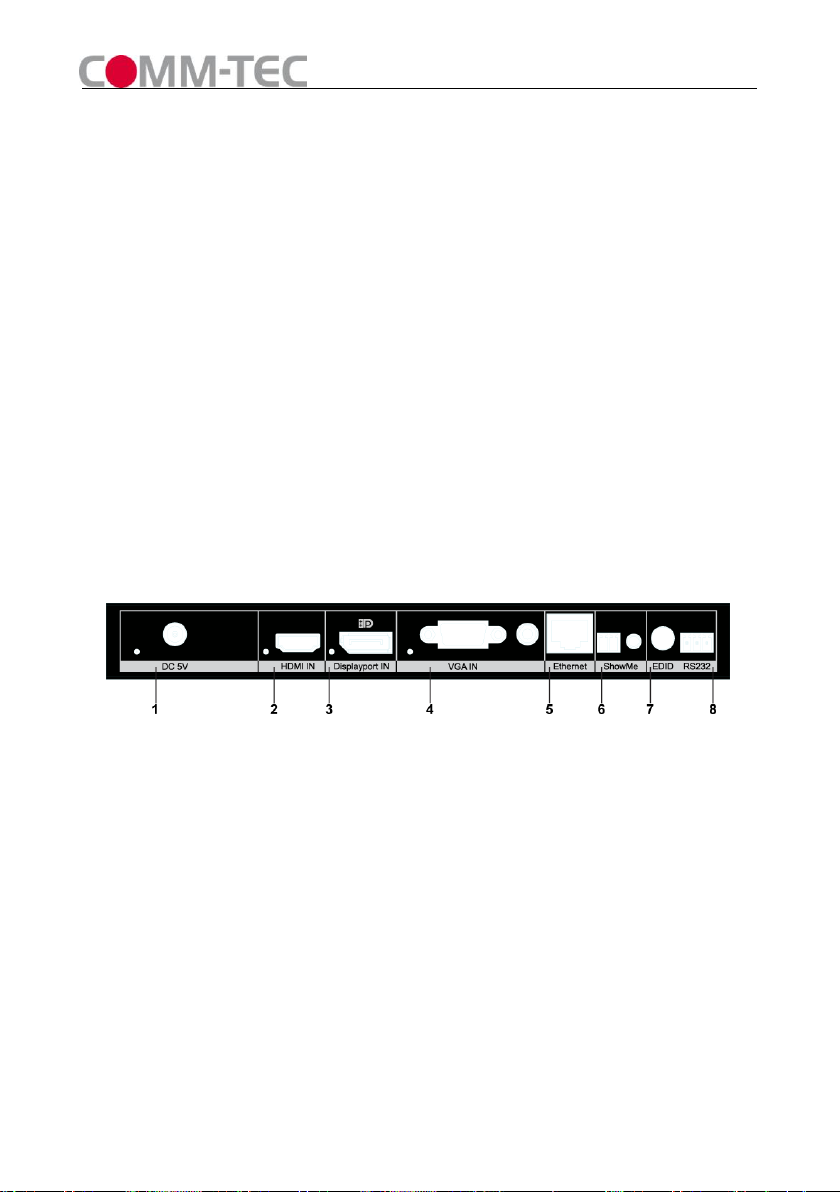
■ Panel Descriptions
1. DaisyNET-TX
Front Panel
1、5VDC Power and Indicator
2、HDMI Input and Indicator
3、Displayport Input and Indicator
4、VGA and Audio Input and Indicator
5、Ethernet Port
6、“ShowMe”Button and Extend Port
7、EDID and Update Switcher
8、RS232 Port
Vers. 1.0 Page 8
Figure 2
Page 9

1、UTP Input
2、UTP Output
2. DaisyNET-RX
1、5VDC Power and Indicator
2、HDMI Output and Indicator
3、Ethernet Port
4、Update Switcher
5、RS232 Port
Side Panel
Figure 3
Front Panel
Figure 4
Side Panel
Figure 5
1、UTP Input
2、UTP Output
Page 9 Vers. 1.0
Page 10

■ Connections and Operations
1) Use two DaisyNET-TXs and two DaisyNET-RXs for example.
2) Connect the HDMI/Displayport/VGA input source ( such as HD-DVD、PS3、
STB、PC etc. ) to DaisyNET-TX 1 and DaisyNET-TX2.
3) Connect the HDMI sink( such as HD-LCD、HD-DLP)to DaisyNET-RX1 and
DaisyNET-RX2.
4) Connect a CAT-5E/6E AWG 23 cable from UTP output of DaisyNET-TX 1 to UTP
input of DaisyNET-TX2.
5) Connect a CAT-5E/6E AWG 23 cable from UTP output of DaisyNET-TX 2 to UTP
input of DaisyNET-RX1.
6) Connect a CAT-5E/6E AWG 23 cable from UTP output of DaisyNET-RX1 to UTP
input of DaisyNET-RX2.
7) Connect Ethernet Port of DaisyNET-TX/RX to PC/Network Switch/Router.
Attention: Please insert and extract cables gently.
■ Connections Diagram:
Vers. 1.0 Page 10
Figure 6
Page 11

Operation Instruction:
1. “ShowMe” Button.
DaisyNET-TX has two statuses: HDBT Pass-through and Local Input.
At HDBT Pass-through status DaisyNET-TX is used as a HDBT Extender (All input
led indicators go out at this status).
Press “ShowMe” button to change to Local Input status.
At Local Input status DaisyNET-TX is used as a 3-Input Switcher.
Press “ShowMe” button to select input port.
To change back to HDBT Pass-through status you must press “ShowMe” button for
more than 3 seconds.
※“ShowMe” button also has an operation-cancel function.
For example: several DaisyNET-TXs are connected together, there is always one
DaisyNET-TX working at Local Input status and others working at HDBT
Pass-through status.
If you mistakenly press “ShowMe” button of a DaisyNET-TX working at HDBT
Pass-through status, the very DaisyNET-TX worked at Local Input status before will
change to HDBT Pass-through status.
To cancel this operation mistake, press “ShowMe” button for more than 3 seconds,
and all DaisyNET-TXs will recover their statuses before the press action.
2. RS232 Control.
For the command set please ask your certified dealer.
Page 11 Vers. 1.0
Page 12

3. Control Software
1) The Interface of PC Control Software
Figure 7
2) Connect COM Port
Connect RS232 port to PC.
Select COM Port and Click “Connect” button, if the COM Port is correct the Connect
status will change to Connected.
Figure 8
3) Set Rotary Switcher to position 9
Assign Address:
Type a 2-digit HEX number (from 00 to FF) in address column, click “Write” to set
Vers. 1.0 Page 12
Page 13

address.
Click “Read” button to get address.
RX LongCable Setting(only for DaisyNET-RX):
Turn ON or Turn OFF LongCable mode
FACTORY RESET:
Click “Reset” button to recover to factory settting.
Figure 9
4) Set Rotary Switcher to position 0~6(recommend 6)
Port Select(only for DaisyNET-TX):
Enter Address of DaisyNET-TX you want to control (If unit has no address you
must assign an address).
Click “Read” button to get current selected input port.
Select Port and click “Write” to set.
Figure 10
EDID Edit(only for HDMI and DP inputs of DaisyNET-TX):
Select HDMI or DP Port, click “Read” button to get current EDID.
Click “Save as” button to save EDID read from display equipment as “*.bin” file.
Click “Open” button to open saved “*.bin” file, select the Input Port in “Port Select”
Page 13 Vers. 1.0
Page 14

column.
Click “Write” button to set EDID of this Input Port the same as “*.bin” file.
Figure 11
5) EDID Copy
Connect DaisyNET-TX UTP OUT to DaisyNET-RX UTP IN.
Set both Rotary Switchers to position 6.
Connect RS232 port of DaisyNET-TX to PC and run PC control software.
Enter Address of DaisyNET-RX you want to read EDID from (If unit has no address
you must assign an address at first).
Select HDMI Port, click “Read” button to get EDID from the display connected to
DaisyNET-RX.
Enter Address of DaisyNET-TX you want to copy EDID to.
Select HDMI Port, click “Write” button to set EDID the same as the display.
6) Cascade Control
Connect DaisyNET-TXs and DaisyNET-RXs as below (all units must be assigned
different address at first).
Figure 12
Set Rotary Switchers of all units to position 6.
Choose one DaisyNET-TX (for example: TX3), connect its RS232 Port to PC,run
PC control software, you can control TX3 and units connected behind TX3’s UPT
OUT port(from TX4 to TXN and RX1 to RXN).
You cannot control units connected before TX3’s UTP IN port (TX1 and TX2).
Vers. 1.0 Page 14
Page 15

※ Setting Instruction:
#
Function
0
1080P stereo (Using Embedded EDID) (note1)
1
1080P 5.1ch (Using Embedded EDID) (note1)
2
1080P 7.1ch(Using Embedded EDID) (note1)
3
1080P 3D stereo (Using Embedded EDID) (note1)
4
1080P 3D 5.1ch (Using Embedded EDID) (note1)
5
1080P 3D 7.1ch (Using Embedded EDID) (note1)
6
Using the specified EDID (Can upload EDID data to
DaisyNET-TX via RS232/RS485) (note2)
7
Upgrade for HDBT RX chip (note3)
8
Upgrade for HDBT TX chip (note4)
9
Upgrade for MCU (note5)
1. Pin definition of extend port for “ShowMe”
2. Pin definition of RS232 Port
3. EDID and Update Switcher Instruction of DaisyNET-TX
Page 15 Vers. 1.0
Page 16

#
Function
0~6
Reserved
7
Upgrade for HDBT RX chip (note3)
8
Upgrade for HDBT TX chip (note4)
9
Upgrade for MCU(note5)
4. Update Switcher of Instruction DaisyNET-TX
Note 1: Only for HDMI Input of DaisyNET-TX.
Note 2: For HDMI and Displayport Input of DaisyNET-TX.
Note 3: Connect RS232 port to PC, use HDBT RX Update Kit to upgrade.
Note 4: Connect RS232 port to PC, use HDBT TX Update Kit to upgrade.
Note 5: Connect RS232 port to PC, use MCU Update Kit to upgrade.
Vers. 1.0 Page 16
Page 17

■ Specifications
Operating Temperature Range
0 to +35°C (32 to +95 °F)
Operating Humidity Range
5 to 90 % RH (no condensation)
Input Video Signal
0.5-1.0 volts p-p
Input DDC Signal
5 volts p-p (TTL)
Video Format Supported
HDMI:1080P/1080i/720P/576P/480P/576i/
480i
DisplayPort & VGA: 800x600/1024x768
1280x1024/1400 x1050/1600 x1200/
1920 x1080/1920 x1200
Output Video
HDMI 1.4 + HDCP
Output Audio
DTS-HD, Dolby-HD
Maximum Transmission Distance
100 meters @ CAT-5e/6 AWG 23
Power Supply
5VDC
Power Consumption
11Watts MAX(DaisyNET-TX)
12Watts MAX(DaisyNET-RX)
Dimensions
223mm H×109mm W×27mm D
Mass (Main unit)
1.3Kg (Pairs)
NOTE1: Specifications are subject to change without notice. Mass and dimensions are
approximate.
Page 17 Vers. 1.0
Page 18

■ Typical Application
Figure 13
■ Maintenance
Clean this unit with a soft, dry cloth. Never use alcohol, paint thinner or benzine to
clean this unit.
■ Product Service
● Provided Service
1) Damage Requiring service: The unit should be serviced by qualified service
personnel if:
The DC power supply cord or AC adaptor has been damaged;
Objects or liquids have gotten into the unit;
The unit has been exposed to rain;
The unit does not operate normally or exhibits a marked change in
performance;
The unit has been dropped or the cabinet damaged.
2) Servicing Personnel: Do not attempt to service the unit beyond that described
in these operating instructions. Refer all other servicing to authorized servicing
personnel.
3) Replacement parts: When parts need replacing ensure the service uses parts
specified by the manufacturer or parts that have the same characteristics as
the original parts. Unauthorized substitutes may result in fire, electric shock, or
other hazards.
Vers. 1.0 Page 18
Page 19

4) Safety check: After repairs or service, ask the service to perform safety
checks to confirm that the unit is in proper working condition.
● Warranty
If your product does not work properly because of a defect in materials or
workmanship, COMM-TEC (referred to as “the warrantor”) will, for the length of the
period indicated as below, Parts (2) Year which starts with the date of original
purchase (“Limited Warranty period”), at its option either (a) repair your product with
new or refurbished parts, or (b) replace it with a new or a refurbished product. The
decision to repair or replace will be made by the warrantor.
During the “Labor” Limited Warranty period there will be no charge for labor. During
the “Parts” warranty period, there will be no charge for parts. You must mail-in your
product during the warranty period. This Limited Warranty is extended only to the
original purchaser and only covers product purchased as new. A purchase receipt or
other proof of original purchase date is required for Limited Warranty service.
● Warranty Limits And Exclusions
1) This Limited Warranty ONLY COVERS failures due to defects in materials
or workmanship, and DOES NOT COVER normal wear and tear or
cosmetic damage. The Limited Warranty ALSO DOES NOT COVER
damages which occurred in shipment, or failures which are caused by products
not supplied by the warrantor, or failures which result from accidents, misuse,
abuse, neglect, mishandling, misapplication, alteration, faulty installation,
set-up adjustments, misadjustment of consumer controls, improper
maintenance, power line surge, lightning damage, modification, or service by
anyone other than a Factory Service Center or other Authorized Service, or
damage that is attributable to acts of God.
2) There are no express warranties except as listed under “limited warranty
coverage”. The warrantor is not liable for incidental or consequential
damages resulting from the use of this product, or arising out of any
breach of this warranty. (As examples, this excludes damages for lost time,
Page 19 Vers. 1.0
Page 20

cost of having someone remove or re-install an installed unit if applicable,
travel to and from the service location, loss of or damage to media or images,
data or other recorded content. The items listed are not exclusive, but are for
illustration only.)
3) Parts and service, which are not covered by this limited warranty, are your
responsibility.
Vers. 1.0 Page 20
Page 21

Deutsche Kurzanleitung
Funktion
Die DaisyNET Geräte erlauben, HDBaseT Signale durch kaskadieren von Geräten
(Daisy Chain) über sehr große Entfernungen zu übertragen. Dabei werden
preiswerte und leicht zu erhaltende Kabel verwendet. Die Anzahl der Geräte ist nicht
begrenzt, es können beliebig viele Geräte zusammengeschaltet werden. Das
geschieht ohne Konfiguration oder andere Anwendereingriffe. Die Geräte werden
verbunden, eingeschaltet und sind betriebsbereit.
Diese Anwendung unterscheidet zwei Gerätearten: Sender und Empfänger. Ein
Sender speist ein AV Signal ein, ein Empfänger gibt das Signal eines Senders
wieder.
Der Sender verfügt über drei verschiedene AV Anschlüsse zum Einspeisen von
Signalen:
HDMI Eingang
DisplayPort Eingang
VGA Eingang mit zusätzlichem Stereo Audio Eingang
Der Anwender kann jetzt auswählen, welchen der Eingänge er an die Empfänger
übertragen möchte. Das geschieht durch eine sogenannte ShowMe Taste, deutsch
Zeig-Mich Taste. Der gewählte Eingang wird durch eine LED am Sender signalisiert.
Sind mehrere Sender hintereinandergeschaltet, ist das Signal aktiv, das von dem
Sender kommt, an dem zuletzt die ShowMe Taste betätigt wurde.
Der Empfänger verfügt über eine HDMI Buchse, an die ein Display oder ein
Projektor angeschlossen wird. An dieser Buchse liegt das Signal an, das am Sender
angewählt wurde. Da es keine Skalierung gibt, liegt das Signal als HDMI Signal mit
der gleichen Auflösung an wie das aktivierte Signal des Senders hat.
Page 21 Vers. 1.0
Page 22

Auch die Empfänger können beliebig oft kaskadiert werden. Alle Empfänger geben
das gleiche Signal wieder.
Anschlüsse
1. DaisyNET-TX (Sender / Transmitter / Tx)
Front Ansicht
Figure 14
1、DC Anschluss für das Netzteil mit Überwurf Mutter und LED Anzeige
2、HDMI Eingang und LED Anzeige, leuchtet, wenn dieser Eingang aktiv ist
3、Displayport Eingang und LED Anzeige, leuchtet, wenn dieser Eingang aktiv ist
4、VGA und Audio Eingang mit LED Anzeige, leuchtet, wenn dieser Eingang aktiv ist
5、Ethernet Port
6、“ShowMe”Taster und Anschluss für externen Taster
7、Multifuktionsschalter für EDID und Update Einstellungen
8、RS232 Port
Seiten Ansicht
1、Link Eingang
2、Link Ausgang
Vers. 1.0 Page 22
Figure 15
Page 23

2. DaisyNET-RX (Empfänger / Receiver / Rx)
Front Ansicht
1、DC Anschluss für das Netzteil mit Überwurf Mutter und LED Anzeige
2、HDMI Ausgang und LED Anzeige
3、Ethernet Port
4、Multifunktionsschalter
5、RS232 Port
Seiten Ansicht
1、Link Eingang
2、Link Ausgang
Inbetriebnahme
Es wird empfohlen, die Geräte im ausgeschalteten Zustand zu verbinden.
Verkabelung des Systems
Figure 16
Figure 17
System mit 1 Sender und 1 Empfänger:
Verbinden Sie die beiden Geräte, in dem Sie ein CAT-5E oder CAT-6 Kabel
(AWG 23) am Sender und Empfänger anstecken. Dabei verbinden Sie den Link
Ausgang des Senders mit dem Link Eingang des Empfängers.
System mit mehreren Sendern und einem Empfänger:
Verbinden Sie alle Sender untereinander, in dem Sie jeweils ein CAT-5E oder CAT-6
Page 23 Vers. 1.0
Page 24

Kabel (AWG 23) an den Sendern anstecken. Dabei verbinden Sie den Link Ausgang
des ersten Senders mit dem Link Eingang des nächsten Senders. Das machen Sie
so oft, bis alle Sender untereinander verbunden sind. Dann verbinden Sie den Link
Ausgang des letzten Senders mit dem Link Eingang des Empfängers.
System mit mehreren Sendern und mehreren Empfängern:
Verbinden Sie alle Sender untereinander, in dem Sie jeweils ein CAT-5E oder CAT-6
Kabel (AWG 23) an den Sendern anstecken. Dabei verbinden Sie den Link Ausgang
des ersten Senders mit dem Link Eingang des nächsten Senders. Das machen Sie
so oft, bis alle Sender untereinander verbunden sind. Dann verbinden Sie den Link
Ausgang des letzten Senders mit dem Link Eingang des ersten Empfängers. Nun
verbinden Sie die Empfänger untereinander auf die gleiche Art wie die Sender:
Link Out des ersten Empfängers mit dem Link In des nächsten Empfängers. Und
auch das machen Sie so oft, bis alle Empfänger untereinander verbunden sind.
Blockschaltbild
Vers. 1.0 Page 24
Figure 18
Page 25

Einschalten
Schließen Sie nun die Netzteile an die Sender und Empfänger an, und ziehen Sie
die Überwurfmuttern handfest an. Bitte keine Zangen oder ähnliche Werkzeuge
dazu verwenden. Nach einstecken der Steckernetzteile ist die Anlage betriebsbereit.
Zu erkennen ist dies an den LEDs links neben dem DC Anschluss.
Quellen anschließen (Sender)
Bitte verwenden Sie zur Verbindung Ihrer Quellen mit den Sendern nur Markenkabel
(z. B. Gefen Kabel). Schließen Sie das Kabel an der Quelle und am Sender an.
Drücken Sie nun die ShowMe Taste so oft, bis die LED links unten an dem von
Ihnen genutzten Eingang des Senders leuchtet. Nach einer kurzen Verzögerung
(HDCP Handshake, EDID Kommunikation) kommt das Signal, das Sie einspeisen,
an der HDMI Buchse des Empfängers an und wird angezeigt.
Machen Sie dies für alle Quellen, die Sie benutzen wollen.
Externen Taster anschließen (Sender)
Schließen Sie die beiden Pole eines Tasters mit Hilfe eine passenden Kabels an
den mitgelieferten 2-poligen Phoenixstecker an. Dann stecken Sie den
Phoenixstecker in den Anschluss <ShowMe> auf der Front des Senders. Damit ist
der externe Taster dem eingebauten Taster parallel geschaltet. Sie dürfen nur
potenzialfreie Kontakte verwenden.
Page 25 Vers. 1.0
Page 26

Vers. 1.0 Page 26
Page 27

Page 27 Vers. 1.0
Page 28

COMM-TEC Vertriebsgesellschaft mbH
Siemens Str. 14
D-73066 Uhingen
f: +49 (7161) 3000 0
w: www.comm-tec.de
Vers. 1.0 Page 28
 Loading...