

Page 1
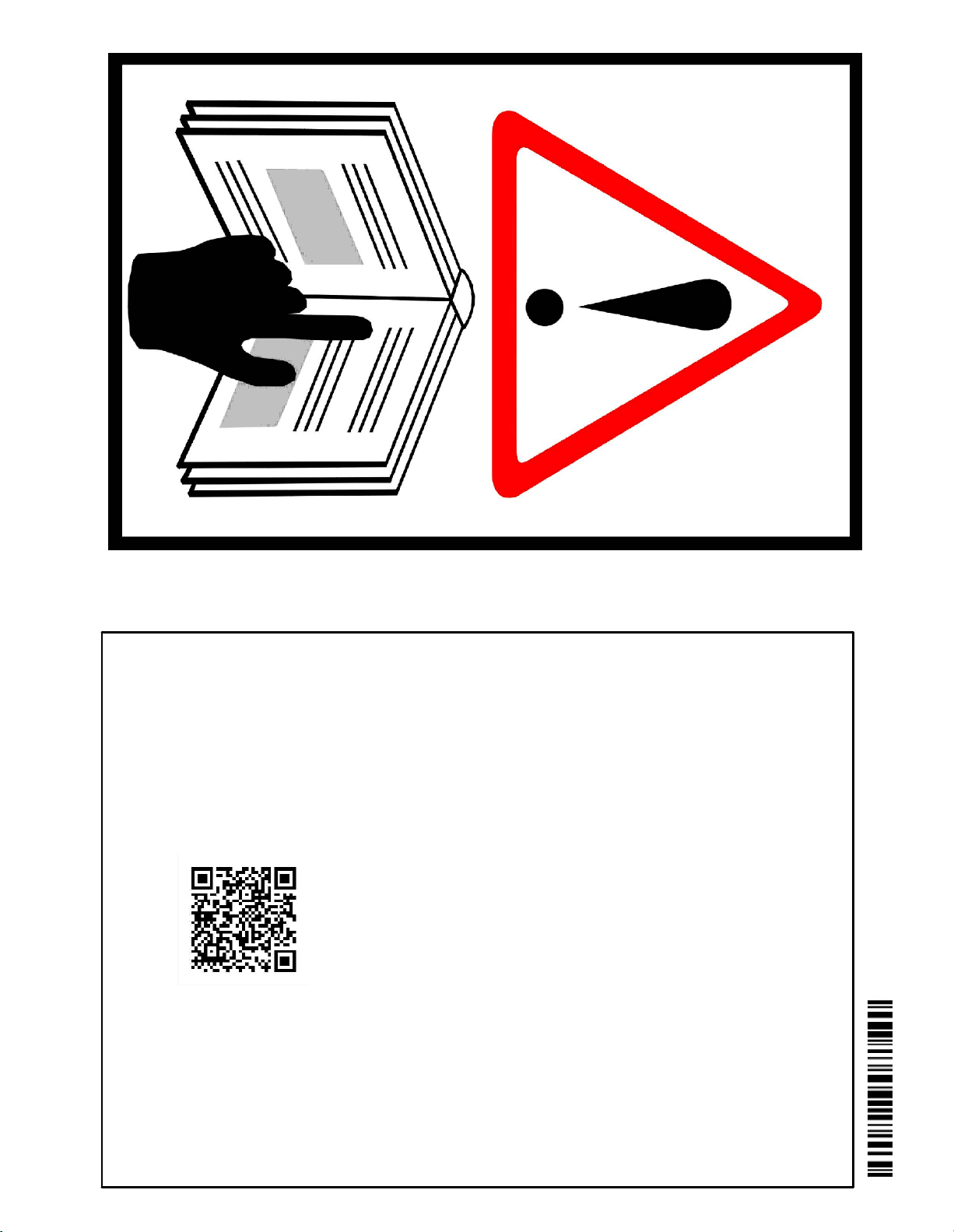
contained within this bulletin must always be followed and take
precedence over any information contained within the video.
Videos provide supplementary information - the instructions
BEFORE UNPACKING
AND ASSEMBLING
IMPORTANT!
THE ANTENNA
MANUAL FULLY
INSTRUCTIONS
INSTALLATION
READ THIS
7706805
Rev:
F
Page 2
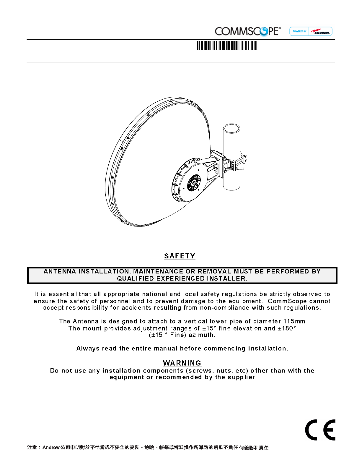
Installation Instructions
ValuLine
3ft (1.0m)
™ 3ft Antennas
This document is for the following:
VHLP(X)3-*** 1.0m ANTENNA
Bulletin
Model Version
7706805
05
Version
03
Status
Status
page
RE
RE
2 of 20
Rev
Rev
F
D
Andrew Solutions
Customer Service 24 hours
U.S.A., Canada, Mexico: 1-800-255-1479
or 1-888-235-5732
U.K.: 0800 250055
Other Europe: +44 592 782 612
Notice: Andrew disclaims any liability or responsibility for the results of improper or unsafe installation, inspection, maintenance, or removal practices.
Aviso: Andrews no acepta ninguna obligacion ni responsabilidad como resultado de practicas incorrectas o peligrosas de instalacion, inspecci6n, mantenimiento o retire.
Avis : Andrew decline toute responsabilite pour les consequences de procedures d'installation, d'inspection, d'entretien ou de retrait incorrectes ou dangereuses.
Hinweis: Andrew lehnt jede Haftung Oder Verantwortung fur Schaden ab, die aufgrund unsachgemaBer Installation, Uberprufung, Wartung Oder Demontage auftreten.
Atencao: A Andrew abdica do direito de toda responsabilidade pelos resultados de praticas inadequadas e sem seguranca de instalacao, inspecao, manutengao ou remocao.
Awertenza: Andrew declina eventual! responsabilita denvanti dell'esecuzione di procedure di installazione, ispezione, manutenzione e smontaggio improprie o poco sicure.
www.commscope.com\andrew
Visit our Web site at www.commscope.com\andrew or contact your local Andrew Solutions representative for more information.
© 2008 CommScope, Inc. All rights reserved.
Andrew Solutions is a trademark of CommScope. All trademarks identified by ® or ™ are registered trademarks or trademarks, respectively, of CommScope. This document is for planning purposes only and is not intended to modify or supplement
any specifications or warranties relating to Andrew Solutions products or services.
Page 3
INSTALLATION
INSTRUCTIONS
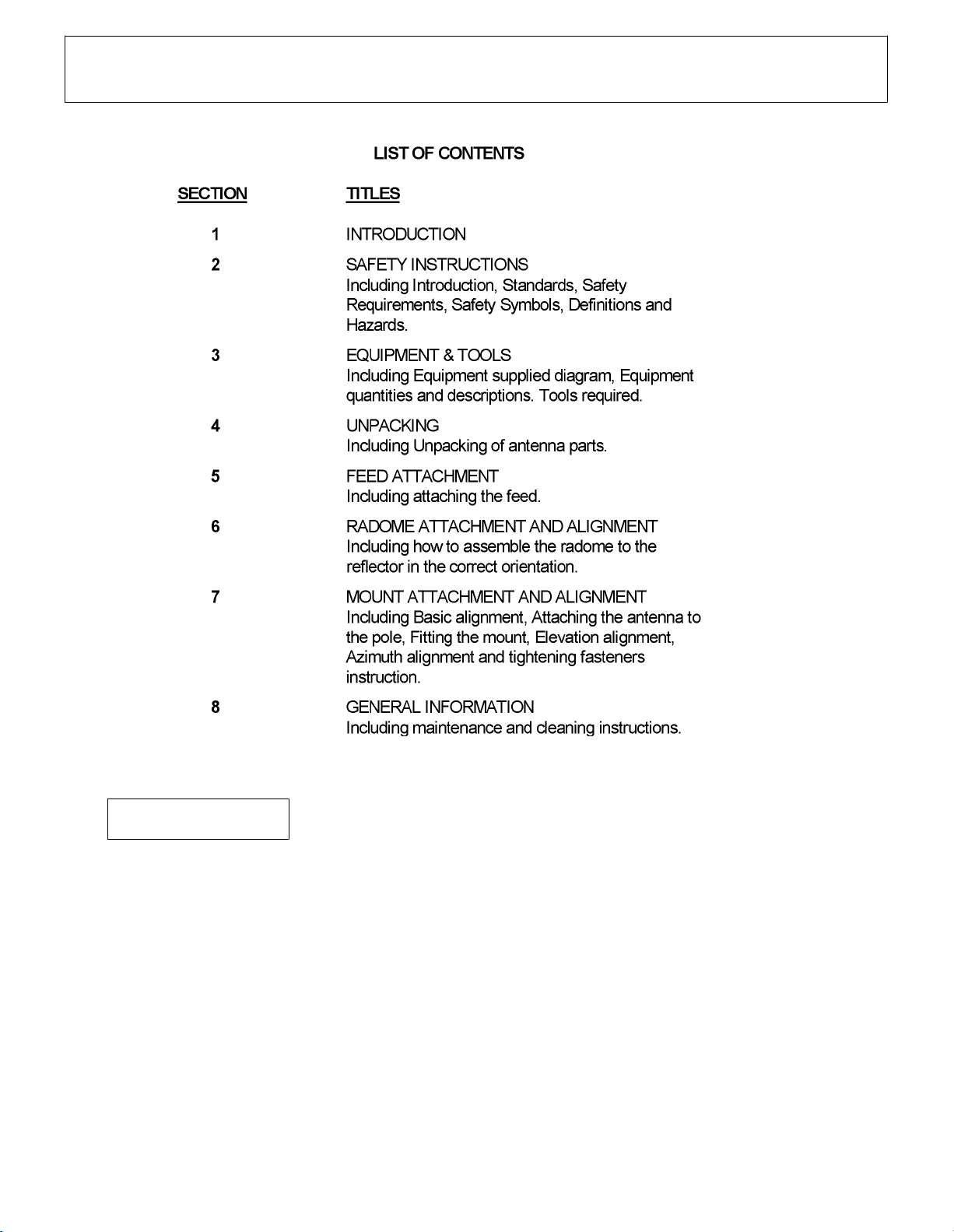
SECTION 1
CONTENTS & INTRODUCTION
7706805
Page 3 of 20
INTRODUCTION
This instruction describes how to assemble a VHLP(X)3 antenna.
The antenna can be mounted with the mount offset to the left or to the right. Offset
left is described in this bulletin, however the images showing offset right installation
are shown at the end of this document.
Page 4

INSTALLATION
INSTRUCTIONS
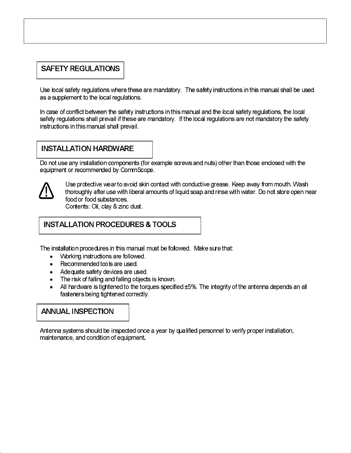
SECTION 2
SATETY INSTRUCTIONS
7706805
Page 4 of 20
Page 5
INSTALLATION
INSTRUCTIONS
SECTION 2
SAFETY INSTRUCTIONS
7706805
Page 5 of 20
Page 6
INSTALLATION
INSTRUCTIONS
SECTION 2
SAFETY INSTRUCTIONS
7706805
Page 6 of 20
Page 7

INSTALLATION
INSTRUCTIONS
EQUPMENT AND TOOLS
SECTION 3
Table 1 Supplied Equipment and Tools
Item
A
B
C
D
D1
E
F
G
G1
G2
G3
G4
G5
G6
H
Qty
1
4
1
1
1
1
1
1
2
2
4
2
2
1
1
2
1
2
2
2
1
4
4
4
2
2
2
1
1
1
16
16
16
Description
Reflector
Radome Rim
Radome
Feed
Feed Installation Kit
Mount: Elevation Adjustment Assembly
Mount: Azimuth Adjustment Clamp
Mount Hardware Kit
Conductive Grease (Tube)
Gloves
M10 x 100lg Hex Hd Screw, sst, pass
M10 Flat Washer, stl, sst, pass
M10 Lock Washer, sst, pass
M10 Hex Nut, stl, sst, pass
M10 x 35lg Hex Hd Screw, stl, galv
M10 Lock Washer, stl, galv
M10 Flat Washer, stl, galv
M10 x 140lg Eyebolt, stl, galv
M10 Lock Washer, stl, galv
M10 Flat washer, stl, galv
M10 Hex Nut, stl, galv
Pipe Clamp, stl, galv
M10 x 130lg Hex Hd Screw, stl, galv
M10 Lock Washer, stl, galv
M10 Hex Nut, stl, galv
M10 x 35lg Hex Hd Screw, sst, pass
M10 Lock Washer, sst, pass
M10 FlatWasher, sst, pass
M10 x 50lg Hex Hd Bolt, sst, pass
M10 Lock Washer, sst, pass
M10 FlatWasher, sst, pass
Radome Rim Assembly Hardware
#12 x 16lg Self Tapping Screw, sst, pass
M6 Lock Washer, sst, pass
M6 FlatWasher, sst, pass
7706805
Page 7 of 20
Contained in Kit Part No
VF-3-FR-14
7679156
7671897
7700025
7700748
Page 8

INSTALLATION
INSTRUCTIONS
Tools
TOOL REQUIRMENTS
SECTION 3
EQUIPMENT AND TOOLS
7706805
Page 8 of 20
Tools Required
Ring and Open Spanner (A/F)
Torque Wrench
Sockets (A/F)
Allen Key (A/F)
Torx Head Driver (T-20)
Cutting Pliers
Compass
General Toolbox
Posidrive/Philips Driver (No2)
Thread Diameter in MM
M4 M8
3mm 6mm 8mm
M10
17mm
17mm
Page 9

INSTALLATION
INSTRUCTIONS
Equipment
SECTION 3
EQUIPMENT AND TOOLS
7706805
Page 9 of 20
A
C
D
B
D1
E
TO
G1 G6
F
H
Page 10

INSTALLATION
INSTRUCTIONS
Unpacking
SECTION 4
UNPACKING
7706805
Page 10 of 20
Leave brace frame attached
to assist assembly of
feed and radome.
(not shown in bulletin views)
External carton hidden to show
internal shipping layout.
Handle reflector and radome with
care at all times.
Do not apply excessive weight on reflector
or radome.
Take care to place reflector and radome on clear
flat ground or use trestles during assembly.
Page 11

INSTALLATION
INSTRUCTIONS
SECTION 4
UNPACKING
7706805
Page 11 of 20
Antenna Offset Left
For installation of Transition unit see manual:
Installing an transition Unit to a 0.3m, 0.6m, 1.0m,
1.2m and 1.8m antenna.
Fit radio per instructions
For installation of Intregration unit see manual:
Installing an integrated Dual Polarization Unit to a
0.3m, 0.6m, 1.0m, 1.2m and 1.8m antenna.
Fit radio per instructions
Page 12

INSTALLATION
INSTRUCTIONS
FEED ATTACHEMENT AND ALIGNMENT
SECTION 5
Feed attachment and alignment
7706805
Page 12 of 20
6GHz, 7GHz and 11GHz Feed Assembly
1
D1
D
SEE SAFETY
NOTE PAGE 4
2
Apply conductive
grease to
surface indicated
Align slot with rib
Assemble 4x screws
Tighten screws to a torque of
1.4Nm
5%
6GHz, 7GHz and 11GHz feed shown assembled
13GHz to 38GHz Feed Assembly
1
D
D1
SEE SAFETY
NOTE PAGE 4
2
Apply conductive
grease to surface
indicated
Align notch with rib
Assemble 4x screws
Tighten screws to a torque of
1.4Nm
5%
13GHz and 38GHz feed shown assembled
Page 13

INSTALLATION
INSTRUCTIONS
RADOME ATTACHMENT AND ALIGNMENT
SECTION 6
Radome attachment and alignment
7706805
Page 13 of 20
B
Align rim edges with
notches in radome.
Note
: The Polystyrene radome is not packing material.
C
B
Rim edges aligned with
notches in radome.
Note position of
alignment arrow.
Page 14

INSTALLATION
INSTRUCTIONS
SECTION 6
RADOME ATTACHMENT AND ALIGNMENT
7706805
Page 14 of 20
Align holes in rim with
slots in reflector
Note position of radome
alignment arrow to reflector
H
Assemble 16x self tapping
screws, lock washers and
washers in a diagonal
sequence.
Tighten screws to a torque
of 2Nm
5%
Page 15

INSTALLATION
INSTRUCTIONS
SECTION 6
RADOME ATTACHMENT AND ALIGNMENT
7706805
Page 15 of 20
Carefully lay antenna on clear, flat ground.
Then remove brace and discard fixings.
Do not apply excessive weight to antenna assembly.
Page 16

INSTALLATION
INSTRUCTIONS
MOUNT ATTACHMENT AND ALIGNMENT
SECTION 7
Mount Attachment and Alignment
7706805
Page 16 of 20
st. st.
galv
galv
galv
G1
E
G3
G3
G2
st. st.
G1
galv
G3
Apply grease to
areas indicated
SEE SAFETY
NOTE PAGE 4
st. st.
G1
F1
G4
galv
galv
G2
galv
G3
G3
galv
Page 17

INSTALLATION
INSTRUCTIONS
SECTION 7
MOUNT ATTACHMENT AND ALIGNMENT
7706805
Page 17 of 20
SEE SAFETY
NOTE PAGE 4
st. st.
38Nm
Apply grease to surface
indicated
G5
5%
G6
G5
st. st.
38Nm
st. st.
38Nm
5%
5%
Page 18

INSTALLATION
INSTRUCTIONS
SLING
SECTION 7
MOUNT ATTACHMENT AND ALIGNMENT
90-120mm Pole
Secure assembled mount to pole ensuring
clamp bolts are seated correctly.
7706805
Page 18 of 20
galv
G4
38Nm
5%
NEVER WALK
UNDER HOISTED
LOADS
Loosen ½ turn,
do not remove.
This mount can only be used
for pole diameters from 90-120 mm
Pole to be structural engineer
approved rigid structural support
Elevation
2
adjustment nut
Loosen ½ turn,
1
do not remove.
1
Loosen ½ turn,
1
do not remove.
Elevation adjustment
Loosen 3 screws (1).
Adjust elevation by bolt head (2).
On completion tighten screws (1) to
38Nm ± 5%
Adjustment Range ±15°
Page 19

INSTALLATION
INSTRUCTIONS
SECTION 7
MOUNT ATTACHMENT AND ALIGNMENT
Loosen screws G1
Loosen screws G2
Pan Left
Pan Right
7706805
Page 19 of 20
Azimuth adjustment
Adjust eyebolt.
On completion tighten
screws
screw
Adjustment Range ±15°
G1
to 50Nm ± 5% and
G2
to 38Nm ± 5%
Torque to
38Nm
5%
Page 20

INSTALLATION
INSTRUCTIONS
8 General Information
8.1 General maintenance
The antenna is designed such that minimal maintenance is required. Other
than strong wind conditions the unit is not subject to abnormal forces and
regular inspection and maintenance should ensure trouble free operation.
8.2 Cleaning of Antenna
If subsequent cleaning of the antenna is required solvent based solutions
must not be used.
SECTION 8
GENERAL INFORMATION
7706805
Page 20 of 20
 Loading...