

Page 1
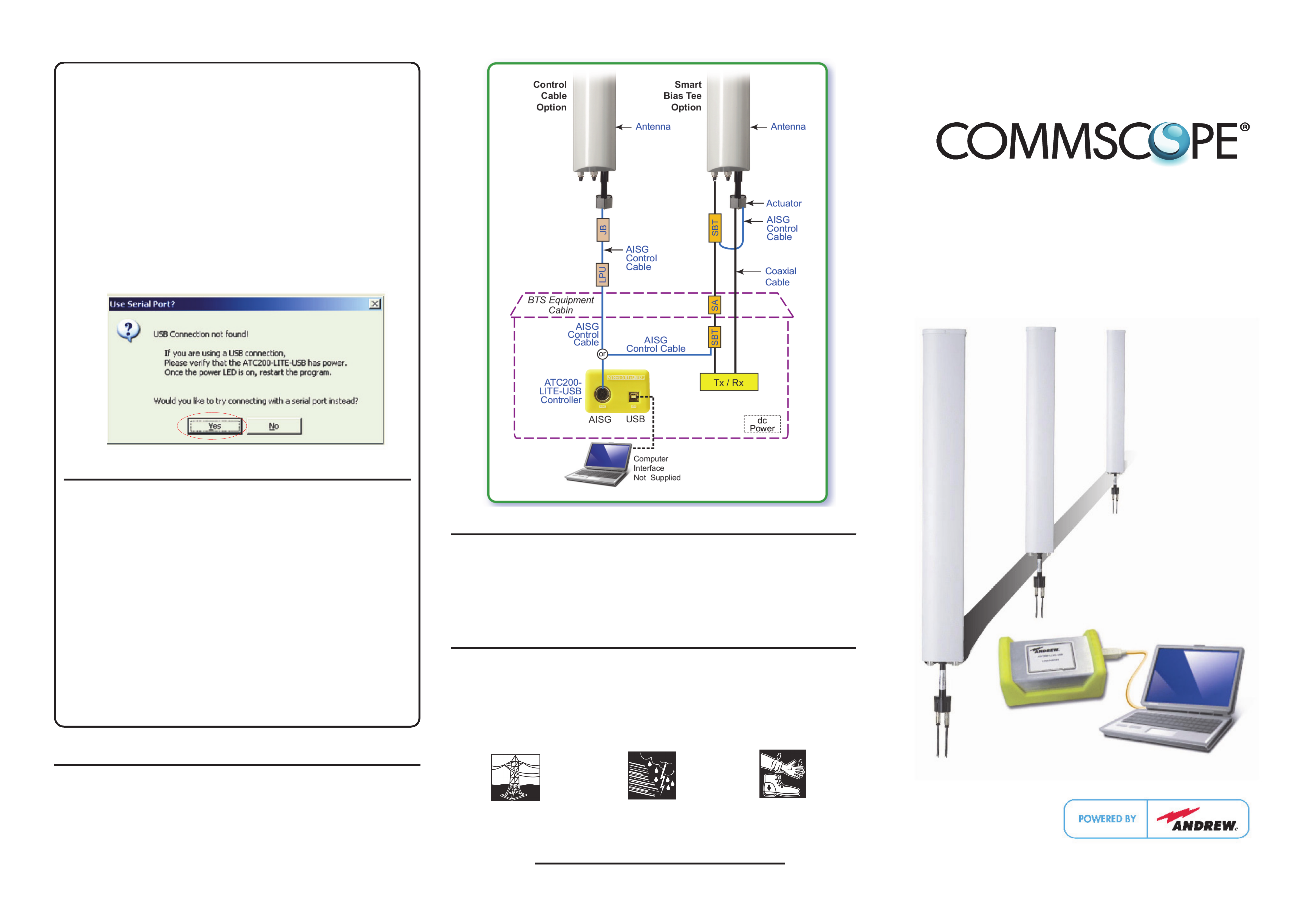
7. Setup for a serial connection.
• Verify that the controller is powered up and connected to the computer using
AN RS-232 serial cable and there is not a USB connection to the
controller.
• Start the ATCLite program. Since a USB connection is not detected, the
computer will prompt you to use a serial connection. Click
Yes
to allow the
computer to search for an available serial port. See Figure 6. COM1 is the
default used, if it is available. If COM1 is not available, the computer will
automatically search for the next available serial port in the range of 1-8.
• After the serial connection has been established, connect the desired length
RET control cable between the controller’s AISG connector and the first
component in the RET system (or actuator that is to be tested before antenna
is mounted on the tower).
8. Device search.
• After the serial or USB connection has been established and the controller
is connected to the RET device/system, a device search can be started. Refer
to the Equipment Installation Overview provided for additional information.
ATC200-LITE-USB
®
Teletilt Control System
Computer Interface Setup
Figure 6. ATC200-LITE-USB Serial Connection.
IMPORTANT Precautions
• Disconnect the ATC200-LITE-USB controller from the RET system at the end
of each session to prevent possible damage to RET devices.
• The controller MUST remain disconnected from the computer and it’s power
supply during the ATCLite software installation process.
• Before installing and operating the ATC200-LITE-USB controller, please
DOWN- LOAD the latest antenna definition file and ATCLite/ATM200 software
files from the Andrew→Products tab on www.commscope.com. Click on
Antennas→Base Station Antenna Systems→Teletilt RET System→Downloads
→Teletilt RET Products Software, Firmware, Tools, and Manuals.
Figure 7. Installed ATC200-LITE-USB Controller System.
WARRANTY NOTICE
Proper installation procedures must be followed when installing and operating RET
equipment. Failure to assure installations are done properly by trained installation personnel
and to follow procedures discussed in this bulletin may cause warranty for such products
to be void.
Andrew requires that all RET installations be pre-tested and configured prior to installation.
Failure to conduct pre-test and pre-installation procedures defined by Andrew will void
warranty.
• Please register online to receive E-mail notifications for updates made to the
software and antenna definition files. Andrew recommends that the website be
checked every 30 days for updated software/documentation.
CommScope
1100 CommScope Place SE P.O. Box 339, Hickory, NC 28603-0339
(828) 324-2200 (800) 982-1708
www.commscope.com/andrew
Notice: CommScope disclaims any liability or responsibility for the results of improper or unsafe installation, inspection, maintenance, or removal practices.
Aviso: CommScope no acepta ninguna obligación ni responsabilidad como resultado de prácticas incorrectas o peligrosas de instalación, inspección, mantenimiento o retiro.
Avis : CommScope décline toute responsabilité pour les conséquences de procédures d’installation, d’inspection, d’entretien ou de retrait incorrectes ou dangereuses.
Hinweis: CommScope lehnt jede Haftung oder Verantwortung für Schäden ab, die aufgrund unsachgemäßer Installation, Überprüfung, Wartung oder Demontage auftreten.
Atenção: A CommScope abdica do direito de toda responsabilidade pelos resultados de práticas inadequadas e sem segurança de instalação, inspeção, manutenção ou remoção.
Avvertenza: CommScope declina eventuali responsabilità derivanti dell’esecuzione di procedure di installazione, ispezione, manutenzione e smontaggio improprie o poco sicure.
注意:CommScope 公司申明对于不恰当或不安全的安装、检验、维修或拆卸 操作所导致的后果不负任何义务和责任。
Customer Service 24 hours
North America: +1-800-255-1479 (toll free)
Any country: +1-779-435-6500
email: acicustomersupportcenter@commscope.com
SAFETY NOTICE
The installation, maintenance, or removal of an antenna requires qualified, experienced
personnel. Andrew installation instructions are written for such installation personnel.
Antenna systems should be inspected once a year by qualified personnel to verify proper
installation, maintenance, and condition of equipment.
Andrew disclaims any liability or responsibility for the results of improper or unsafe
installation practices.
Wear shoes with rubber soles and Do not install near power lines.
heels. Wear protective clothing
including a long-sleeved shirt and
rubber gloves.
Power lines, telephone lines, and
guy wires look the same. Assume
any wire or line can electrocute
you.
Do not install on a wet or windy
day or when lightning or thunder
is in the area. Do not use metal
ladder.
@2013 CommScope Bulletin 639559
Installation Training Available at Andrew Institute
Bulletin 639559 • Revision F • August 2013
Page 2
ATC200-LITE-USB Program Installation and Controller Setup
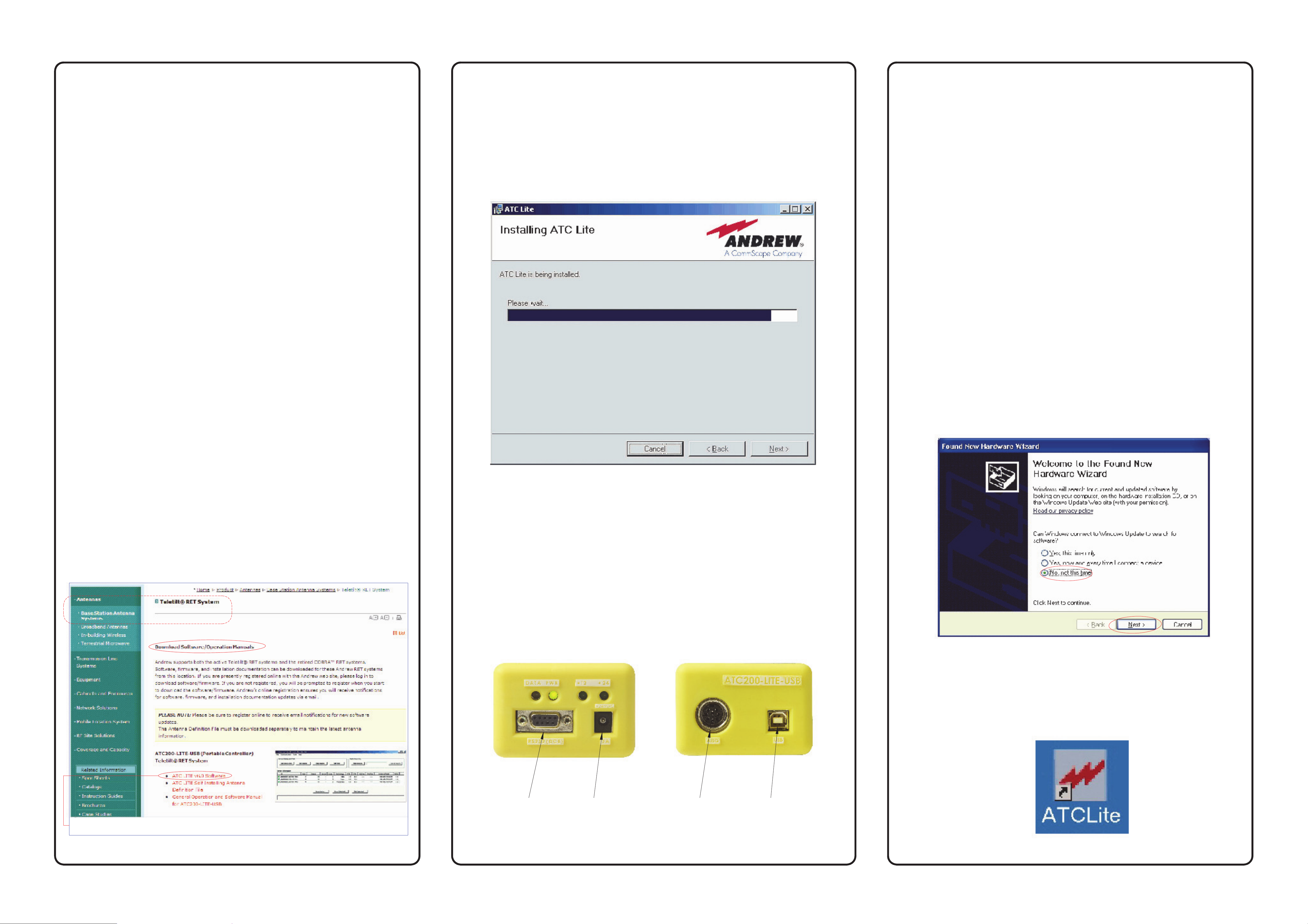
3. Program installation.
5. Setup for a USB connection and driver installation.
General information.1.
This bulletin provides a quick reference approach to establishing
communication between the ATC200-LITE-USB Teletilt controller and a
®
local PC/laptop (seeBulletin 639536 for the complete user guide). This
controller is equipped with both a USB port for user friendly connectivity to a
local PC/laptop and a serial port for applications where a USB port is not
available on the PC.
Pre-Installation Notes:
• Andrew recommends that you register online to receive notifications for
updates made to the software and antenna definition file. It is also
recommended that the Andrew web site be checked every 30 days for
updated software/documentation.
• Disconnect the controller from the computer and its power supply. Do not connect the
controller to the computer at any time during the software installation.
• Double-click on the setup file (eg.
ATC Lite W/"XX" Setup.msi
). Note that the number
preceding the file extension represents the software version.
• Follow the on-screen prompts to complete the software installation.
• Figure 2 shows the active installation screen.
This procedure is
only
required the first time the controller is accessed through
a USB connection.
Ensure there are no serial connections to the controller.
The ATCLITE software must be installed (but not running) prior to installing the
USB driver.
A. After the controller software has been installed, connect the supplied 24 Vdc
power converter to the dc IN port on the controller.
B. Connect the supplied USB cable to the controller and the local PC/laptop.
The PC will detect and notify you that it has found a new device.
C. Make the following selections to install the USB driver for the
ATC200-LITE-USB controller when prompted by the PC/laptop:
The controller MUST remain disconnected from the computer and its
•
power supply during the ATCLite software installation process.
• Before installing antennas equipped with actuators to the tower, each
actuator should be connected to the controller and tested for proper
operation. Refer to the ATC200-Lite-USB User Guide (Bulletin 639536) for
detailed guidance. Guides for system installation and operation instruction
are included with the ATC200-LITE-USB controller or Teletilt antenna.
• It is recommended that prior to antenna installation on the tower, the serial
number, antenna type, and location the antenna will be installed at on the
tower be recorded on the Site Configuration Worksheet provided.
• Site information can be saved on the PC/laptop for future reference. Although
data is stored in the actuator, it cannot be saved in the controller.
• Select
No, not this time
, and click on
Next
from the first screen. See Figure
4.
• Select
• Click on
Install from a list . . .
Browse
and locate the C:\Program Files\Andrew
, and click on
Corporation\ATCLite directory. Click on
Next
OK
, then click on
from the second screen.
Next
from the
third screen.
• When prompted, click on
the final screen.
Continue Anyway
, and then click on
Finish
from
D. After installing the USB driver, connect the desired length RET control cable
between the controller’s AISG connector and the first component in the
RET system (or actuator that is to be tested before the antenna is mounted
on the tower). See Figure 7.
2. Program download.
• Download the ATC Lite software zip file. From the Andrew→Products tab on
www. commscope.com, click on Antennas→Base Station Antenna Systems
→Teletilt RET System→Downloads→Teletilt RET Products Software,
Firmware, Tools, and Manuals. Select the
ATC Lite W/"XX" Software
link
(See Figure 1).
• This zip file can be placed in any directory on the PC’s local C:\ drive.
Double-click on the zip file to extract the ATC Lite setup file and its
supporting installation documentation. Double click on the setup file
(eg.
ATC Lite W/"XX" Setup.msi
) to begin the installation process. Note that
the number shown in the filename represents the software release version.
Figure 2. ATC200-LITE-USB Controller Installation Screen.
4. Controller interface connections.
• The controller serves as an interface between a local PC/laptop and the ATM200 RET
actuator/antenna system. The ATC200-LITE-USB controller provides signal level
conversion from a PC to RS-485 (used in the ATM200 actuators), as well as power
to the ATM200 actuators that are attached to the antennas.
• LEDs on the controller are used to indicate power and data communication. The
ATC200-LITE-USB controller is equipped with a USB port, as well as a RS-232 serial
port for flexibility in connecting to a PC. See Figure 3.
Figure 4. The New Hardware Wizard Installs the USB Driver.
6. After the USB driver has been installed and the controller is connected
to the RET device/system, the controller software can be launched at
any time.
Double click on the ATCLite icon (Figure 5) placed on the desktop to start
controller operation.
Click on software link, and choose Save to download the zipped file to your PC.
Figure 1. ATC200-LITE-USB Controller Software Download.
RS-232
Serial Port dc IN Port AISG Port
Figure 3. ATC200-LITE-USB Controller End Panels.
USB Port
Figure 5. ATCLite Application Icon.
 Loading...