

Page 1

SYSTIMAX® InstaPATCH® 360
Traffic Access Point (TAP)
Solution
Design Guide
www.commscope.com
Page 2

Contents
Introduction 3
How Does a TAP Work? 3
The TAP Ecosystem 4
InstaPATCH 360 TAP Module Family 4
InstaPATCH 360 TAP Fan-out Array Cords 5
InstaPATCH 360 TAP Pre-terminated Fiber Cables 5
Traffic Monitoring System 5
Fiber Cabling System Design with TAPs 6
Example 1—10Gbps Ethernet 6
Example 2—8Gbps Fibre Channel 8
Optical Channel Loss Evaluation with TAPs 10
Loss Evaluation of Main Traffic Channels 10
Loss Evaluation of Shorter Monitor Channels 11
Loss Evaluation of Longer Monitor Channels 12
TAP Installation 12
Ordering Information 13
References 15
2
Page 3

Introduction
The need for real-time network traffic monitoring in today’s intelligent data center has become
compelling. Data center network administrators need to gain better visibility of their networks,
optimize the performance of mission-critical applications and, more importantly, secure their
networks.
In fiber-optic networks, a traffic access point (TAP) can be integrated into the fiber cabling
infrastructure, enabling network traffic monitoring from physical layer (layer 1) and above
in real-time fashion with zero packet loss. Because TAPs continuously pass all traffic running
between the endpoint network devices with zero latency—while duplicating that exact same
traffic to the monitor ports simultaneously—TAPs are one of the most efficient ways to monitor
traffic and network link quality in data center and telecom carrier networks.
This design guide will help you understand and design fiber cabling systems using CommScope
SYSTIMAX® InstaPATCH® 360 TAP solutions to support applications and enable real-time
network traffic monitoring at the same time.
How Does a TAP Work?
TAP modules provide an important feature for data center monitoring and management. A TAP
module is a compact package of fiber-optic couplers or splitters that can be used to passively
divert a fixed percentage of light energy away from main transportation channels as a way
to monitor the traffic status or content in real time without disrupting the main channel traffic.
The optical couplers or splitters inside a TAP module are the key components that split the light
energy from the input port into two output ports according to designed split ratio.
Figure 1 shows example signal paths of 12-fiber multimode fiber (MMF) TAP Modules. On the
right side of the diagram the rear surface of the TAP modules provide one Multiple-Fiber PushOn/Pull-off (MPO) connector serving the main traffic channels for connecting to a trunk cable,
and another MPO connector (red) serving the monitoring channels for connecting to monitoring
equipment via MPO-LC array cords. On the left side of the diagram the front surface of the
modules provide 12 LC receptacles for patching.
Couplers are unidirectional components and are arranged in an alternating sequence for
duplex transceiver connectivity at the LC connectors. As shown in the upper part of Figure
1, Channel 1 of the LC connectors receives traffic from Channel 1 of the MAIN MPO port
after a portion of its optical signal is split into Channel 1 of the TAP MPO connector. Other
odd-numbered LC connectors follow the same signal flow. The lower part of Figure 1 shows
Channel 2 of the LC connectors, which serves only for signal input, and its signal is split
between Channel 2 of the MAIN MPO and the TAP MPO connectors. Other even-numbered
LC connectors follow the same signal flow.
3
Page 4

Figure 1. Fiber TAP signal path illustrations
TAP modules, therefore, must be tested or deployed with channel directionality in mind. The
transmitter (or the meter source) must always be connected to the input of the coupler. Also, the
receiver (or the meter detector) must always be connected to the outputs of the optical coupler.
Connecting in an opposite direction will not affect the main traffic, but will result in a lack of
output from the monitoring channels.
The TAP Ecosystem
The TAP ecosystem mainly consists of the InstaPATCH 360 pre-terminated fiber cables,
InstaPATCH 360 TAP modules, InstaPATCH 360 TAP Fan-out Array Cords, and the monitoring
equipment. The TAP modules, combined with the array cords, provide flexible choices to
network designers for various network configurations. The monitoring equipment is designed
to detect and analyze traffic collected from the TAP.
InstaPATCH 360 TAP Module Family
The optical TAP is a completely passive device integrated in the optical network physical layer
and is invisible to potential intruders. Due to different network application environments, the TAP
family has a variety of different formats, such as number of fibers, fiber type, and split ratio.
Figure 2 shows some examples of the CommScope TAP family, including combinations of
12-fiber or 24-fiber, MMF or Single-mode fiber (SMF), and 70/30 or 50/50 split ratio.
(a)
SMF 12-fiber,
Front view
Figure 2. Front and rear views of InstaPATCH 360TM TAP modules
(b)
SMF 12-fiber,
Rear view
(c)
MMF 24-fiber,
Front view
(d)
MMF 24-fiber,
Rear view
4
Page 5

The MMF TAPs are designed to operate at 850nm wavelength. The MMF TAP can be
deployed with bend-insensitive or traditional OM3 or OM4 fiber cabling. The single-mode
fiber TAPs are optimized for operation at 1310nm wavelength.
The designed split ratios of the TAP modules are selected for compatibility with the supported
applications. The available split ratios are 70/30 and 50/50. The first number of each split
ratio indicates the percent of the input power split off to the main channel output. The second
number indicates the percent of the input power split off to the monitor output. The optical
power budgets of some applications, such as those for Ethernet on MMF, are sufficiently robust
to support transmission through the higher loss of a 50% split or a 70% split, while others,
such as many of those for Fibre Channel on MMF, are not as robust and must rely on the
stronger signals from a 70% split. Refer to SYSTIMAX 360 Traffic Access Point (TAP) Solutions
Performance Specification Volume 5 for channel topology design limits for all supported
applications.
The InstaPATCH 360TM modules insert into the panel openings of InstaPATCH 360 shelves
and panels and can be placed side by side with InstaPATCH 360DM modules. This permits
flexibility in patch panel placement in new or retrofit situations. InstaPATCH 360TMs follow the
alpha/beta orientation conventions of Method B array polarity just like 360DMs.
1
InstaPATCH 360 TAP Fan-out Array Cords
In addition to the TAP modules, the InstaPATCH 360 TAP solution includes a family of MPOLC Fan-out Array Cords that provide great flexibility for network designers. The InstaPATCH
360 TAP Fan-out Array Cords are designed to be connected to the TAP port(s) of InstaPATCH
360 TAP modules, and pass network traffic to a third-party network monitoring system. The
InstaPATCH 360 TAP Fan-out Array Cords are configured as unpinned MPO to 12 simplex LC
array cord assemblies. They are available in Plenum or LSZH materials, and LazrSPEED 550
fiber (OM4) or TeraSPEED fiber (single-mode).
InstaPATCH 360 Pre-terminated Fiber Cables
InstaPATCH 360 cables terminated with unpinned MPO plugs attach to InstaPATCH 360TM
modules. They are available in Plenum or LSZH sheath materials. LazrSPEED 300 (OM3) and
LazrSPEED 550 (OM4) cables are used with multimode 360TM modules, and TeraSPEED
(OS2) cables are used with single-mode 360TM modules.
Traffic Monitoring System
Another major part of the monitoring system is the monitoring and analysis equipment, including
receivers, analysis hardware and software, as shown in Figure 3. The monitoring system
receives the signal from the TAP and analyzes the traffic. Commercially available monitoring
systems include those from Virtual Instruments®, GigaMON® and others.
5
Page 6
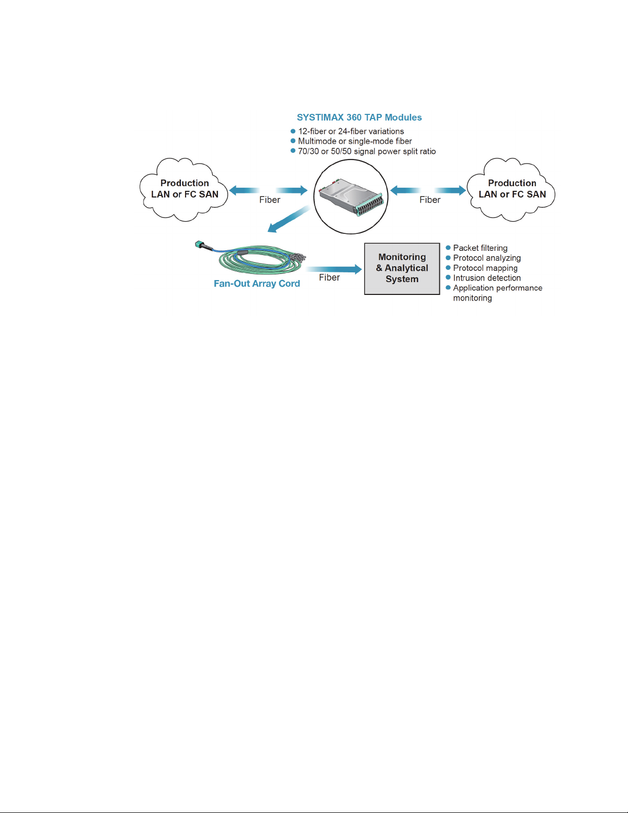
Figure 3. A typical TAP-based monitoring system
Fiber Cabling System Design with TAPs
While industry standards for Ethernet and Fibre Channel are not expressly designed to
support the added loss of TAPs, it is possible with careful engineering and high performance
cabling systems to deploy TAPs in networks and retain useful channel topologies.
approaching the design of a TAP solution for a particular application, many factors need
to be taken into consideration. These include the loss of the TAP splitter, length and number
of connections within the main and two monitor channels, the intended application (e.g.
8G Fibre Channel or 10G Ethernet), and the monitor equipment capability. Fortunately the
SYSTIMAX InstaPATCH 360 Fiber TAP Solution Performance Specification provides channel
topology limits that account for many of these factors to simplify the design process. The
following two sections provide practical design examples using this Performance Specification
for a 50/50 MMF TAP solution and a 70/30 MMF TAP solution.
Example 1—10Gbps Ethernet
Figure 4 shows an example of a 10Gbps Ethernet network retrofitted with an optical TAP. In
this case, an InstaPATCH 360 standard module (360DM module) located at the cross-connect
point—which is the middle point of the channel—is replaced with an InstaPATCH 360 TAP
module (360TM module).
3–5
When
6
Page 7

Figure 4. Retrofit example: 10GE channel with 50/50 TAP module replacing
MPO/LC module at central cross connect
A quick check of the Performance Specification reveals that the 10GBASE-S power budget
supports both 50/50 and 70/30 split ratios for the main channel. The ability to support a
50/50 split ratio also permits the monitor equipment to use minimally standards-compliant
transceivers, and therefore the monitor channels may also be designed using the same
topology limit tables as the main channel. This choice offers a straight forward design that
requires no design consultation with the monitor equipment company. In comparison, the
selection of the 70/30 split ratio, while improving the signal strength of the main channels,
requires better than minimally compliant transceivers in the monitor gear and therefore
necessarily involves consultation with the monitor gear company for design limits. Here we will
illustrate the design approach using a 50/50 split ratio TAP module.
Looking at Figure 4, determine the main channel length by adding up the cord and cable
lengths that form the main channel from left to right:
10m+80m+5m+80m+10m=185m
The length of the monitor channel from the left side is:
10m+80m+5m=95m
The length of the monitor channel from the right side is:
10m+80m+5m+5m=100m
In this network configuration, the main traffic channel has four MPO connections and four
LC connections (the connections to the active equipment are not counted), and the channel
length is 185m. The longer monitoring channel, which is the right side in this case, has three
MPO connections and three LC connections, and the channel length is 100m. The shorter
monitor channel, which is on the left side in this case, has three MPO connections and one
7
Page 8

LC connection, and the channel length is 95m. Of these three channels, the main channel is
the most demanding having both the longest length and the highest number of connections.
Table 1 is an extract from the SYSTIMAX InstaPATCH 360 Fiber Tap Solutions Performance
Specifications —Volume Five for 10GBASE-S on LazrSPEED 550 and the 50/50 split ratio
TAP. The cell at the intersection of 4 MPOs and 4 LCs indicates a supportable distance of
240 m, which greater than the length of the main channel, so the design is supportable with
LazrSPEED 550 cabling. Checking the LazrSPEED 300 capability in Table 2 we see that it
supports 130m with four MPO connections and four LC connections, so LazrSPEED 300 is not
an option for this channel topology.
LazrSPEED 550, 50/50 split ratio
# LC
Connections* with:
1 970 (295) 940 (285) 900 (275) 870 (265) 840 (255) 790 (240)
2 950 (290) 920 (280) 870 (265) 840 (255) 800 (245) 770 (235)
3 920 (280) 890 (270) 850 (260) 820 (250) 770 (235) 740 (225)
4 900 (275) 870 (265) 820 (250) 790 (240) 750 (230) 710 (215)
5 870 (265) 840 (255) 800 (245) 750 (230) 720 (220) 670 (205)
6 850 (260) 800 (245) 770 (235) 720 (220) 690 (210) 640 (195)
1 MPO 2 MPOs 3 MPOs 4 MPOs 5 MPOs 6 MPOs
Table 1. Channel topology limits for 10GBASE-S on LazrSPEED 550 for a 50% TAP
channel
LazrSPEED 300, 50/50 split ratio
# LC
Connections* with:
1 660 (200) 590 (180) 560 (170) 520 (160) 460 (140) 430 (130)
2 620 (190) 560 (170) 520 (160) 490 (150) 430 (130) 390 (120)
3 590 (180) 520 (160) 490 (150) 460 (140) 390 (120) 330 (100)
4 560 (170) 520 (160) 460 (140) 430 (130) 360 (110) 300 (90)
5 520 (160) 490 (150) 430 (130) 360 (110) 330 (100) 260 (80)
6 490 (150) 430 (130) 390 (120) 330 (100) 260 (80) 200 (60)
1 MPO 2 MPOs 3 MPOs 4 MPOs 5 MPOs 6 MPOs
Table 2. Channel topology limits for 10GBASE-S on LazrSPEED 300 for a 50% TAP
channel
Example 2—8Gbps Fibre Channel
Figure 5 shows an example of an 8G Fibre Channel (8GFC) link designed with an optical
TAP. The TAP is inserted into the fiber patch panel on the right side near the FC Storage Area
Network (SAN) switch.
8
Page 9

Figure 5. Example 8GFC channel with TAP placed near SAN switch.
A quick check of the Performance Specification reveals that the minimally standards-compliant
8GFC power budget for MMF supports only the 70% output of a 70/30 TAP module for
the main channels. The 30% output for the monitor channels requires better than minimally
standards-compliant transceivers in the monitor gear and therefore necessarily involves
consultation with the monitor gear company for design limits for the monitor channels. The
intended MMF bandwidth grade (i.e. LazrSPEED 550 (OM4), LazrSPEED 300 (OM3)), the
monitor channel lengths and maximum channel losses will be required by the monitor company
to perform the analysis. Section 5 provides guidance on how to determine the maximum
channel loss using the SYSTIMAX Solutions Link Loss Calculator2.
Looking at Figure 5, determine the main channel length by adding up the cord and cable
lengths that form the main channel from left to right:
10m+90m+10m=110m
The length of the monitor channel from the storage array side is:
10m+90m+10m=110m
The length of the monitor channel from the SAN switch side is:
10m+10m=20m
In this network configuration, the main traffic channel has two MPO connections and two
LC connections (the connections to the active equipment are not counted), and the channel
length is 110m. Table 3 is an extract from the SYSTIMAX InstaPATCH 360 Fiber Tap Solutions
Performance Specifications—Volume Five for 8GFC on LazrSPEED 550 and the 70/30 split
ratio TAP. The cell at the intersection of 2 MPOs and 2 LCs indicates a supportable distance
of 115 m, which is greater than the 110 m length of the main channels, so the design is
supportable with LazrSPEED 550 cabling for the main channels.
9
Page 10

The longer monitor channel has three low-loss MPO connections, one low-loss LC connection,
and the length is 110m. The shorter monitor channel has one low-loss MPO connection,
one low-loss LC connection, and the length is 20m. Follow the procedure of Section 5 to
provide the monitor company the information they need to evaluate your channel design for
compatibility with their equipment.
LazrSPEED 550, 70/30 split ratio, MAIN (70%) output
# LC
Connections* with:
1 480 (145) 430 (130) 360 (110) 280 (85) 200 (60) 100 (30)
2 440 (135) 380 (115) 310 (95) 230 (70) 130 (40) 0 (0)
3 390 (120) 330 (100) 250 (75) 150 (45) 30 (10) 0 (0)
4 340 (105) 280 (85) 180 (55) 70 (20) 0 (0) 0 (0)
5 300 (90) 210 (65) 100 (30) 0 (0) 0 (0) 0 (0)
6 250 (75) 130 (40) 0 (0) 0 (0) 0 (0) 0 (0)
Table 3. Channel topology limits for 8GFC on LazrSPEED 550 for 70% TAP channel
1 MPO 2 MPOs 3 MPOs 4 MPOs 5 MPOs 6 MPOs
Optical Channel Loss Evaluation with TAPs
The following subsections are presented in three parts, each of which examines one of the
three different channels topologies created when deploying TAPs—one main channel topology
and two monitor channel topologies. Channel loss evaluation of the two monitor channels
is necessary when designing channels with 70/30 TAP modules. Channel loss evaluation
provides the monitor equipment company information to evaluate the proposed channel for
interoperability with their equipment. This is because the high loss of a 30% split requires better
than minimally complaint receivers which are proprietary to the monitor company.
While the main channel loss is independent of the placement of the TAP module within the
channel, the monitor channel loss depends on the placement of the TAP module. This is
because there are two different channel topologies from monitor to each end of the channel.
These two monitor channel topologies are usually of different lengths. Consequently in the
following evaluation we refer to these two channel topologies as “shorter monitor channels”
and “longer monitor channels”.
Loss Evaluation of Main Traffic Channels
Figure 6 shows the main traffic channels of an optical link with a 70/30 TAP inserted. The
pink arrow shows one direction signal flow, but traffic in the other direction sees the same loss.
All cabling is LazrSPEED 550 (OM4). The trunk cable is 80m long, the LC/LC equipment
cords are 10m each. Using SYSTIMAX Solutions Link Loss Calculator Version 7.1 plug in the
following factors: a 70 percent TAP with two low-loss MPO connections, two low-loss LC
connections, and 100m of “LazrSPEED® with InstaPATCH @ 850nm” fiber cable. Using those
inputs, the maximum loss of the main channels is calculated as 2.88dB.
10
Page 11
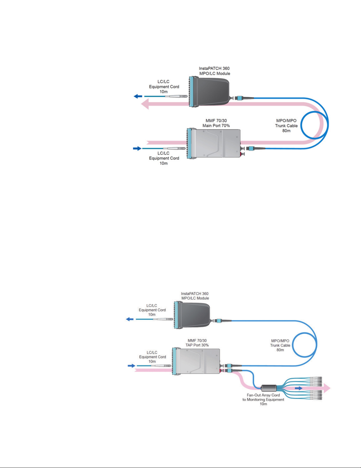
Figure 6. Illustration of the main traffic channel signal paths
Loss Evaluation of Shorter Monitor Channels
Figure 7 shows the monitor channel signal path from the end closest to the monitor. The
LC/LC equipment cord is 10m long, and the fan-out array cord connected to the monitoring
port is also 10m long. Using SYSTIMAX Solutions Link Loss Calculator, Version 7.1 plug in the
following factors: select the 30 percent TAP, one low-loss MPO connection, one low-loss LC
connection, and 20m “LazrSPEED® with InstaPATCH @ 850nm” fiber cable. Using those inputs
the maximum loss of the even-numbered monitor channels is calculated as 7.13dB.
Figure 7. Illustration of the monitor channel signal paths for signals from the near
end of the channel
11
Page 12

Loss Evaluation of Longer Monitor Channels
Figure 8 shows the monitor channel signal path from the end farthest from the monitor. The
trunk cable is 80m long. Both LC/LC equipment cord and fan-out array cord are 10m long.
Using SYSTIMAX Solutions Link Loss Calculator, Version 7.1 plug in the following factors: select
a 30 percent TAP, three low-loss MPO connections, one low-loss LC connection, and 100m
“LazrSPEED® with InstaPATCH @ 850nm” fiber cable. Using those inputs the maximum loss of
the odd-numbered monitor channels is calculated as 7.73dB.
Figure 8. Illustration of the monitor channel signal paths for signals from the far
end of the channel
Provide the calculated maximum losses, monitor channel lengths, and fiber type including
bandwidth grade of MMF (i.e. OM3 or OM4) to the monitor gear company for channel
evaluations when using 70/30 TAP modules.
TAP Installation
Please refer to the Instruction Sheet for InstaPATCH 360 TAP modules for detailed installation
information in eCatalog.
InstaPATCH 360 TAP solution should be utilized in conjunction with the InstaPATCH 360
pre-terminated fiber solutions. Due to the insertion losses of field-installable MPOs, it’s not
recommended to use InstaPATCH 360 TAP solution with fiber trunks terminated with field
installable MPOs.
12
Page 13

Ordering Information
InstaPATCH 360 TAP solution can be ordered by contacting CommScope Sales.
Please visit the CommScope eCatalog at the following link.
http://www.commscope.com/Product-Catalog/Enterprise/Product/Fiber/
MATERIAL ID PRODUCT CODE DESCRIPTION
760188284 360TM-12LC-LS-70:30 TAP module, 12F duplex LCs, OM4,
70/30 signal split (Main/TAP)
760188292 360TM-12LC-LS-50:50 TAP module, 12F duplex LCs, OM4,
50/50 signal split (Main/TAP)
760188300 360TM-12LC-SM-70:30 TAP module, 12F duplex LCs, OS2,
70/30 signal split (Main/TAP)
760188318 360TM-12LC-SM-50:50 TAP module, 12F duplex LCs, OS2,
50/50 signal split (Main/TAP)
760188607 360TM-24LC-LS-70:30 TAP module, 24F duplex LCs, OM4,
70/30 signal split (Main/TAP)
760188615 360TM-24LC-LS-50:50 TAP module, 24F duplex LCs, OM4,
50/50 signal split (Main/TAP)
760188623 360TM-24LC-SM-70:30 TAP module, 24F duplex LCs, OS2,
70/30 signal split (Main/TAP)
760188631 360TM-24LC-SM-50:50 TAP module, 24F duplex LCs, OS2,
50/50 signal split (Main/TAP)
Table 3. List of InstaPATCH 360 TAP modules
13
Page 14

MATERIAL ID PRODUCT CODE DESCRIPTION
760196501 360TM ARRAY, PLNM, LS,
MP(f)-LC(s), M05
760196519 360TM ARRAY, PLNM, LS,
MP(f)-LC(s), M06
760196527 360TM ARRAY, PLNM, LS,
MP(f)-LC(s), M07
760196642 360TM ARRAY, PLNM, LS,
MP(f)-LC(s), M19
760196659 360TM ARRAY, PLNM, LS,
MP(f)-LC(s), M20
760196303 360TM ARRAY, PLNM, SM,
MP(f)-LC(s), M05
760196311 360TM ARRAY, PLNM, SM,
MP(f)-LC(s), M06
760196329 360TM ARRAY, PLNM, SM,
MP(f)-LC(s), M07
760196444 360TM ARRAY, PLNM, SM,
MP(f)-LC(s), M19
760196451 360TM ARRAY, PLNM, SM,
MP(f)-LC(s), M20
760197327 360TM ARRAY, LSZH, LS,
MP(f)-LC(s), M05
760197335 360TM ARRAY, LSZH, LS,
MP(f)-LC(s), M06
760197343 360TM ARRAY, LSZH, LS,
MP(f)-LC(s), M07
760197467 360TM ARRAY, LSZH, LS,
MP(f)-LC(s), M19
760197475 360TM ARRAY, LSZH, LS,
MP(f)-LC(s), M20
760198143 360TM ARRAY, LSZH, SM,
MP(f)-LC(s), M05
760198150 360TM ARRAY, LSZH, SM,
MP(f)-LC(s), M06
760198168 360TM ARRAY, LSZH, SM,
MP(f)-LC(s), M07
760198283 360TM ARRAY, LSZH, SM,
MP(f)-LC(s), M19
760198291 360TM ARRAY, LSZH, SM,
MP(f)-LC(s), M20
Table 4. Partial list of InstaPATCH 360TM TAP Fan-out Array Cords with metric
lengths
Note: The available lengths of the array cords (partially listed here) are from 1 to 20 meters,
with an incremental length of 1 meter. Unlisted array cords are also available in lengths from
4 to 65 feet with an incremental length of 1 foot.
TAP fan-out cables, MPO (unpinned), 12
simplex LCs, OM4, plenum, 5m
TAP fan-out cables, MPO (unpinned), 12
simplex LCs, OM4, plenum, 6m
TAP fan-out cables, MPO (unpinned), 12
simplex LCs, OM4, plenum, 7m
TAP fan-out cables, MPO (unpinned), 12
simplex LCs, OM4, plenum, 19m
TAP fan-out cables, MPO (unpinned), 12
simplex LCs, OM4, plenum, 20m
TAP fan-out cables, MPO (unpinned), 12
simplex LCs, OS2, plenum, 5m
TAP fan-out cables, MPO (unpinned), 12
simplex LCs, OS2, plenum, 6m
TAP fan-out cables, MPO (unpinned), 12
simplex LCs, OS2, plenum, 7m
TAP fan-out cables, MPO (unpinned), 12
simplex LCs, OS2, plenum, 19m
TAP fan-out cables, MPO (unpinned), 12
simplex LCs, OS2, plenum, 20m
TAP fan-out cables, MPO (unpinned), 12
simplex LCs, OM4, LSZH, 5m
TAP fan-out cables, MPO (unpinned), 12
simplex LCs, OM4, LSZH, 6m
TAP fan-out cables, MPO (unpinned), 12
simplex LCs, OM4, LSZH, 7m
TAP fan-out cables, MPO (unpinned), 12
simplex LCs, OM4, LSZH, 19m
TAP fan-out cables, MPO (unpinned), 12
simplex LCs, OM4, LSZH, 20m
TAP fan-out cables, MPO (unpinned), 12
simplex LCs, OS2, LSZH, 5m
TAP fan-out cables, MPO (unpinned), 12
simplex LCs, OS2, LSZH, 6m
TAP fan-out cables, MPO (unpinned), 12
simplex LCs, OS2, LSZH, 7m
TAP fan-out cables, MPO (unpinned), 12
simplex LCs, OS2, LSZH, 19m
TAP fan-out cables, MPO (unpinned), 12
simplex LCs, OS2, LSZH, 20m
14
Page 15

References
1. SYSTIMAX® InstaPATCH® 360 Traffic Access Point (TAP) Solutions Performance
Specifications, Vol.5, June 18, 2014.
2. SYSTIMAX Solutions—Link Loss Calculator, Version 7.1.
3. IEEE 802.3, “IEEE standards for Ethernet”, December 2012.
4. ANSI/INCITS 479-2011, “Information technology—Fibre Channel—Physical Interfaces—
5 (FC-PI-5)”, November 2011.
5. INCITS/TR-46-2011, “Information technology—Fibre Channel Methodologies for Signal
Quality specification (FC-MSQS) (ANSI/INCITS Technical Report)”, 2011.
15
Page 16

We’re proud to be a part
of your network’s story.
Here at CommScope, we embrace our role as a
trusted resource, partner, and facilitator. We create the
infrastructure that connects the world and evolves with
every advance in technology. By investing all of our
capabilities, resources, relationships, and products into
your toughest challenges, we continue our long history
of solving problems together—paving the way for new
ideas and fresh ways of thinking.
We’re a trusted resource and partner around the
world because we’re invested in you: your people,
your networks, your success. It inspires us to build
relationships and infrastructure…connect people and
technologies across protocols, oceans, and time
zones…and share what we learn along the way.
This is our promise to you.
This is CommScope.
www.commscope.com
Visit our website or contact your local CommScope representative for more information.
© 2014 CommScope, Inc. All rights reserved.
All trademarks identified by ® or ™ are registered trademarks or trademarks, respectively, of CommScope, Inc.
This document is for planning purposes only and is not intended to modify or supplement any specifications or warranties relating to CommScope products or services.
CommScope is certified according to ISO 9001, TL 9000, and ISO 14001.
TP-108221-EN (09/14)
 Loading...