

Page 1
TECP-90-801 Issue 4 October 2017
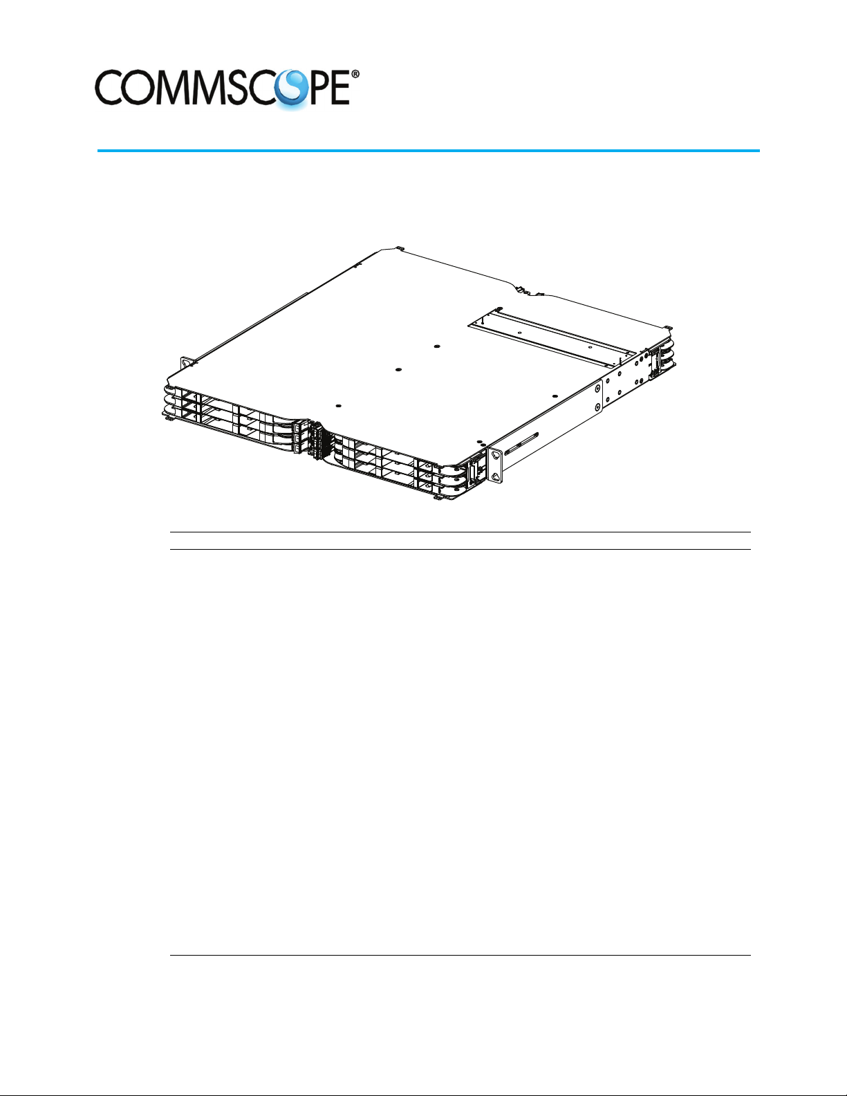
Quareo High Density Equipment Panel (HDEP)
User Manual
25111-A
Content Page
INTRODUCTION ............................................................................. 2
RELATED PUBLICATIONS ...................................................................... 3
1 PRODUCT DESCRIPTION .................................................................. 4
1.1 Physical Description ............................................................... 4
1.2 Panel Electronics ................................................................. 5
1.3 Status LEDs on Front Panel and Modules ................................................. 5
1.4 Specifications ................................................................... 6
2 UNPACKING AND INSPECTION .............................................................. 7
3 INSTALLATION......................................................................... 7
3.1 Overview ....................................................................... 8
3.2 Tools and Hardware Needed ......................................................... 8
3.3 Rack Installation ................................................................. 8
3.4 Installing the Vertical Cable Guides (VCGs) ...............................................10
3.5 Grounding the Panel ...............................................................13
3.6 Installing the Management Unit .......................................................13
3.7 Connecting the Ethernet Cable and AUX Power Cable ........................................14
3.8 Connecting the Control Cable .........................................................14
3.9 Connecting the Panel to the Quareo Network ..............................................15
4 INSTALLING MODULES AND IFC CABLES.......................................................15
5 TECHNICAL ASSISTANCE..................................................................16
300100102902 Rev D Page 1
This product is covered by one or more U.S.patents or their foreign equivalents. © 2017 CommScope.
For patents, see http://www.commscope.com/ProductPatent/ProductPatent.aspx All Rights Reserved.
Page 2
TECP-90-801 • Issue 4 • October 2017
INTRODUCTION
This manual describes the Quareo High Density Equipment Panel (HDEP) and documents all
procedures required in installing it. Included are the procedures required to mount the panel on
a rack, ground the panel, and install Vertical Cable Guides (VCGs).
Note: This manual does not contain instructions for installing modules in access trays.
Instructions unique to the various module types are provided through QR code access to
the CommScope Field Support Link. This online site contains videos, animations, and
other information for the module being installed. The QR code is a label on the top of the
panel; the Field Support Link is accessed using a visual recognition app on a smart phone.
Note: This manual does not contain instructions for the Web Interface used when the
panel is installed to configure it within the Quareo network. Instructions for this are
provided in TECP-90-805.
Revision History
ISSUE DATE REASON FOR CHANGE
1 5/2014 Original.
3 January 2017 Reformatted for CommScope.
4 October 2017 Updated to remove incorrect logo.
Trademark Information
CommScope (logo), CommScope, and Quareo are trademarks
Applicable Standards
UL 60950-1, 2nd Edition, 2007-03-27 (Information Technology Equipment - Safety - Part 1:
General Requirements)
CSA C22.2 No. 60950-1-07, 2nd Edition, 2007-03 (Information Technology Equipment Safety
- Part 1: General Requirements)
Admonishments
Important safety admonishments are used throughout this manual to warn of possible hazards to
persons or equipment. An admonishment identifies a possible hazard and then explains what
may happen if the hazard is not avoided. The admonishments — in the form of Dangers,
Warnings, and Cautions — must be followed at all times.
.
Danger: Danger
injury, death, or substantial property damage if the hazard is not avoided.
Warning: Warning
injury, death, or substantial property damage if the hazard is not avoided.
Page 2
© 2017 CommScope. All Rights Reserved.
is used to indicate the presence of a hazard that will cause severe personal
is used to indicate the presence of a hazard that can cause severe personal
Page 3
Caution: Caution is used to indicate the presence of a hazard that will or can cause minor
personal injury or property damage if the hazard is not avoided.
General Safety Precautions
Danger: To prevent electrical shock, never install panel in a wet location or during a lightning
storm. When installing or modifying telephone lines, disconnect lines at the network interface
before working with uninsulated lines or terminals.
TECP-90-801 • Issue 4 • October 2017
Caution: When
connecting the equipment to the power sources, check the equipment nameplate
rating to avoid overloading circuits which may cause damage to over-current protection devices
and supply wiring.
Caution: If
the panel is installed in a closed or multi-rack assembly, the operating temperature
of the rack environment may be greater than the ambient temperature. Be sure to install the
panel in an environment that is compatible with the maximum rated ambient temperature. See
Specifications.
Caution: Installation
of the equipment in a rack should be such that air flow to the equipment is
not compromised.
Caution: When
mounting equipment in the rack make sure mechanical loading is even to avoid
a hazardous condition, such as loading heavy equipment in the rack unevenly. The rack should
safely support the combined weight of all equipment it supports.
Caution: Reliable
earthing of rack-mounted equipment should be maintained. Particular
attention should be given to supply connections other than direct connections to the branch
circuit (e.g. use of power strips).
Caution: This
equipment is to be installed only in Restricted Access Areas (dedicated
equipment rooms, equipment closets, etc.) in accordance with Articles 110-16, 110-17, and 11018 of the National Electrical Code, ANSI/NFPA 70
RELATED PUBLICATIONS
Listed below are related manuals and their publication numbers. Copies of these publications can
be ordered by contacting the CommScope Technical Assistance (refer to Topic 5 on Page 16).
Title/Description Publication Number
Quareo High Density Equipment Panel Web Interface User Manual TECP-90-805
Quareo Management Unit Installation Manual TECP-90-806
© 2017 CommScope. All Rights Reserved.
Page 3
Page 4
TECP-90-801 • Issue 4 • October 2017
1 PRODUCT DESCRIPTION
1.1 Physical Description
The Quareo High Density Equipment Panel (HDEP) is a fiber optic connector panel with six
access trays, each providing a mounting location for one adapter pack or cabled module. A
single access tray provides 24 LC connections for a panel total capacity of 144 LC connections.
The panel has mounting brackets intended for a 19-inch (48. 26 cm) rack-mount. Extender
brackets
shipped with the ETSI extender brackets already installed. The panel may also be mounted in a
cabinet providing a 19-inch, 23-inch, or ETSI rack mount configuration.
This panel contains electronics that enable connection information to be acquired and supplied
to
physical layer management system. Refer to Topic 1.2 on Page 5.
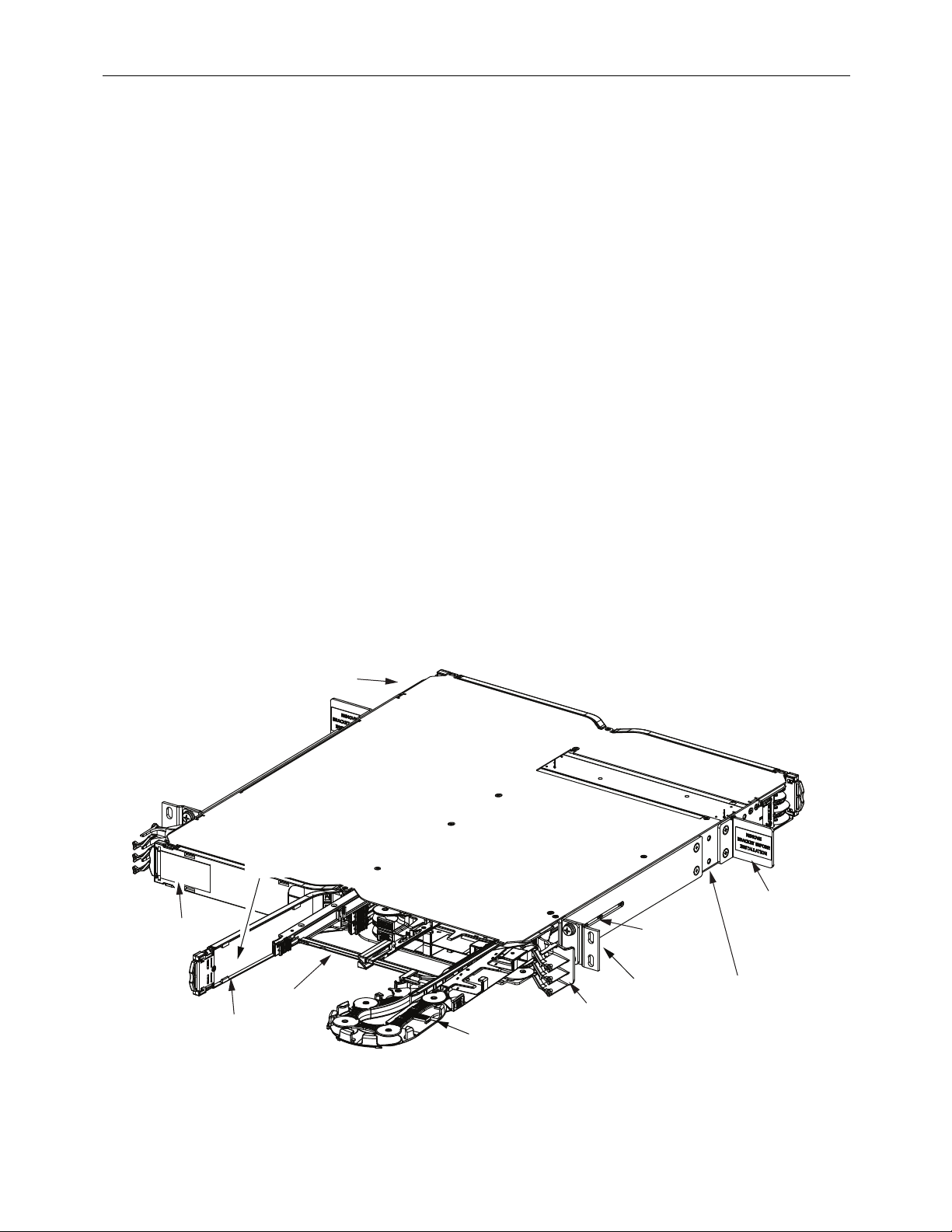
Figure 1 shows the main physical features of the 1RU panel, including the following:
configure the panel for an ETSI or 23-inch (58.42 cm) rack-mount. The panel is
the Infrastructure Configuration Manager (ICM), the central system software of the Quareo
QR CODE
ACCESS TRAY
• Access
• Access
• Designation
• QR
trays—hold adapter packs or cabled modules; open to front or rear of the panel.
tray doors—protect adapter pack or cabled module when access tray is closed.
cards—are used to record cable destinations.
code—is a label with a pattern recognizable by a visual recognition app on a smart
phone. The QR code causes the smart phone to link to the CommScope Field Support
Link, which contains user instructions specific to the 1RU panel.
GROUNDING
LOCATION
DESIGNATION CARDS
(LOCATED ON
BACKSIDE OF DOOR)
SHIPPING
BRACKET (2X)
REMOVED
BEFORE
INSTALLATION
RACK
OFFSET
SCREWDOWN
LOCATIONS
25316-C
DOOR (4X)
ACCESS
TRAY
CABLE
MANAGEMENT
LINKAGE
VERTICAL CABLE
GUIDE (4X)
(PROVIDED)
RACK
OFFSET
ADJUSTMENT
SLOT
MOUNTING
BRACKET
(WITH
EXTENSION)
Page 4
© 2017 CommScope. All Rights Reserved.
Figure 1. Quareo HDEP Physical Features
Page 5

TECP-90-801 • Issue 4 • October 2017
• Mounting brackets—are intended for a 19-inch (48. 26 cm) rack-mount. Extender
brackets configure the panel for an ETSI or 23-inch (58.42 cm) rack mount. The panel is
shipped with the ETSI extender brackets installed.
• Cable
or closed to ensure cables are not crimped or misaligned impeding tray movement.
• Rack
panel) provides offset options of 3, 4, 5, or 6.5 inches (7.62, 10.24, 12.7, or16.5 cm).
• Grounding
The Quareo HDEP is orderable with universal adapter packs designed to accept a variety of
connector
information, see Table 1. Adapter packs can be installed from the front or rear by snapping them
into position; no screws or tools are required. Cabled modules (ordered separately) are also
available
for this panel. For more information, see Table 1.
1.2 Panel Electronics
The Quareo HDEP has electronics that enable it to function by ICM in a Quareo physical
management system. A typical Quareo network includes both fiber and copper connector panels
and non-managed representations of the input and output devices (such as switches) to which
cables are connected.
Assuming all connections to the Quareo HDEP are made with managed modules and cables,
electronics provide an ICM user with the ability to know, on a real time basis, whether
these
each port of the Quareo HDEP is connected and to what it is connected (what other equipment
and port). On a network level, the user may plan future connections and disconnections of
equipment assisted by a dynamic schematic view of connectivity of the entire network.
management linkage—holds and repositions cables when access trays are opened
offset adjustment slot and rack offset screwdown locations—(on each side of
location—provides a mounting stud for a ground wire.
types. Available adapter pack types include LC-LC and MPO-MPO. For more
1.3 Status LEDs on Front Panel and Modules
The Quareo HDEP has six Light Emitting Diodes (LEDs) on the front middle of the panel
(Figure 2). These LEDs are identical in function. There is one LED for each access tray. The
LEDs have two states: unlit or lit (green).
FRONT MIDDLE OF PANEL
LEDs
Figure 2. Status LEDs
ONE
ACCESS
TRAY
25315-A
Page 5
© 2017 CommScope. All Rights Reserved.
Page 6

TECP-90-801 • Issue 4 • October 2017
The status LEDs on the front panel blink green at start-up. If a LED for a particular access tray
does not light at start-up, either there is no module installed in the access try or a module is
present but due to malfunction or mis-seating is unknown to the Quareo system. A blinking
green LED after start-up indicates an individual LED is lit for one of the connectors in the
module installed in that access tray. To identify which LED this is, open the access tray and
check the individual LEDs on the ports.
A LED lit for an individual port indicates that ICM has identified this port as requiring attention
for an active Work Order to be completed. The LED stays on until the entire Work Order is
successfully completed. There can be multiple steps in a Work Order such as Connect two ends
of cable, Disconnect two ends of cable, Insert one end of cable, Extract one end of cable, and so
on. LED blinking is different for Connect and Disconnect Work Orders. For a Connect Work
Order step, LEDs blink green on the two ports that need to be connected. For a Disconnect
Work Order step, LEDs blink yellow on the two ports that need to be disconnected.
A LED for an individual port or all LEDs for all ports on a particular module can also be lit for
identification purposes using the Quareo Panel Interface Web Browser.
1.4 Specifications
Table 1 lists specifications for the Quareo HDEP.
Table 1. Quareo High Density Equipment Panel
PARAMETER SPECIFICATION REMARKS
Electrical
Voltage 37-57 VDC, 48 VDC nominal
Input current 350mA (maximum (per IEEE 802.3af) at 48 VDC
Environmental
Operating conditions
Storage conditions
Mechanical
DimensionsDxWxH 13.35 in (33,9 cm) D x 19.01 in (48.29 cm)Wx1.7
Weight 4.1 lb. (1.86 kg.)
Components
Supported Adapter Packs* LC-LC 24 fibers (12 duplex ports)
+14F to +140F(10Cto+60C)
5% to 95% RH
40F to +158F(40C to +70C) 10% to 95% RH
in (4.32 cm) H
MPO-MPO 192 fibers (eight 24-fiber
No condensation
No condensation
ports)
Page 6
© 2017 CommScope. All Rights Reserved.
Page 7

TECP-90-801 • Issue 4 • October 2017
Table 1. Quareo High Density Equipment Panel
PARAMETER SPECIFICATION REMARKS
Supported Modules LC-MPO (straight configuration; left or right) 24 fibers (one 24-fiber rear
port)
LC-MPO (flipped configuration; left or right) 24 fibers (two 12-fiber rear
ports)
LC-MPO (10G HD; left or right) 24 fibers (two 12-fiber rear
ports)
LC cabled module Dual zip 24-fiber cable
2 UNPACKING AND INSPECTION
Unpack and inspect the various components as follows:
1. Inspect the exterior of the shipping container(s) for evidence of rough handling that may
have
damaged the components in the container.
2. Unpack each container while carefully checking the contents for damage and verify with
3. If damage is found or parts are missing, file a claim with the commercial carrier and notify
4. Refer to Topic 5 on Page 16 if you need to contact CommScope.
5. Save all shipping containers for use if the equipment requires shipment at a future date.
3 INSTALLATION
Warning: To prevent electrical shock, never install panel in a wet location or during a lightning
storm. When installing or modifying telephone lines, disconnect lines at the network interface
before working with uninsulated lines or terminals.
Caution: This
equipment rooms, equipment closets, etc.) in accordance with Articles 110-16, 110-17, and 11018 of the National Electrical Code, ANSI/NFPA 70.
Panel
Caution: If the panel is installed in a closed or multi-rack assembly, the operating temperature
of the rack environment may be greater than the ambient temperature. Be sure to install the
panel in an environment that is compatible with the maximum rated ambient temperature. See
Specifications.
the
packing slip.
CommScope
Customer Service. Save the damaged cartons for inspection by the carrier.
equipment is to be installed only in Restricted Access Areas (dedicated
© 2017 CommScope. All Rights Reserved.
Page 7
Page 8

TECP-90-801 • Issue 4 • October 2017
3.1 Overview
Installation involves the following:
• Mounting the panel on a rack;
• Grounding the panel;
• Connecting the network control cable;
• Connecting power;
• Connecting the panel to the Quareo network;
• Installing controlled modules and cables.
3.2 Tools and Hardware Needed
Tool and hardware requirements are listed in Table 2.
Table 2. Installation Tools and Hardware Needs
CONSIDERATION DESCRIPTION
Tools Needed #1 Phillips Screwdriver,
Rack Mounting 19” EIA/WECO/ETSI Rack Mounting. Use supplied #12-24 screws and #2
Grounding Secure panel to ground. Use #1 Phillips Screwdriver to tighten the 10-32
Incoming IFC Cable
Clamping
3.3 Rack Installation
The Quareo HDEP is shipped with extender brackets already attached for mounting the panel in
an ETSI equipment rack. The extender brackets may be removed for mounting the panel in a
19-inch (482.6mm) equipment rack. Mounting brackets for a 23-inch (58.42 cm) mounting are
supplied as ship along items.
Check the work order to determine the panel location in the rack or cabinet. Mounting hardware
shipped loose. Each panel is secured with either 12-24 screws, M6 hardware, or TrueNet
is
quick fit hardware depending on type of mounting used.
#2 Phillips Screwdriver,
3/16” Standard Screwdriver
Phillips Screwdriver to secure the panel to the rack or cabinet or use supplied
M6 screws, cage nuts and #2 Phillips Screwdriver to secure the panel to the
rack or cabinet or use TrueNet®Frame “quick fit” solution
screws through the ground lug (provided) into the panel ground PEM nuts.
Ground cables are NOT provided with the panel
Use supplied cable clamps and 3/16” standard screwdriver to secure the
incoming IFC cable
®
Use the following procedure to mount the panel (refer to Figure 3).
Page 8
© 2017 CommScope. All Rights Reserved.
Page 9

TECP-90-801 • Issue 4 • October 2017
Caution:
If panel is installed in a closed or multi-rack assembly, the operating temperature of the
rack environment may be greater than the ambient temperature. Be sure to install the panel in an
environment that is compatible with the maximum rated ambient temperature. See Specifications.
Caution: Installation of the equipment in a rack should be such that air flow to the equipment is
not compromised.
1. Obtain the following tools and equipment:
• Flat blade or Phillips screwdriver (type to match mounting screws)
• Locate mounting hardware required.
26574-A
LOCKWASHER
(4)
12-24 x 1/2 IN.
SCREW (4)
MOUNTING
BRACKET
RACK
FRONT
FLANGE
Figure 3. Mounting Panel
(Shown With 23-Inch Extender Brackets Installed)
2.
Determine what rack size is being used, and reconfigure the
mounting brackets if required
for the frame (or cabinet) in which the panel is being installed.
a. For an ETSI rack or cabinet, leave the panel as received from the factory with extender
brackets
attached.
b. For a19-inch rack or cabinet, remove the ETSI brackets and leave the inner mounting
brackets
in place.
c. For an 23-inch rack or cabinet, remove the ETSI brackets and in their place install the
23-inch
extender brackets (provided in ship along kit).
© 2017 CommScope. All Rights Reserved.
Page 9
Page 10

TECP-90-801 • Issue 4 • October 2017
3. Determine the rack offset position to be used. If other than the 3-inch position that the
panel is shipped in from the factory, remove the two screws holding the rack adjustment
bar, and slide it off the mounting posts and relocate onto the desired mounting posts.
Tighten down the screws in the new rack offset position.
Note: For
location of rack offset slot, see Figure 1 on Page 4.
4. Locate the equipment rack mounting space that is specified for the panel.
Note: Ethernet
Note: If
installing panel in a Q-Frame (Cross-Connect Solution), make ground connection
cabling distance to and from the panel should not exceed 328ft. (100m).
to panel before securing panel in the rack.
5. Place panel in the assigned mounting space and align the holes in the mounting brackets
the holes in the equipment rack. See Figure 3 on Page 9.
with
6. Secure panel to equipment rack using the appropriate hardware. Torque these screws to
approximately
Caution: When
27 pound-inches (3.1 Newton meters).
mounting equipment in the rack make sure mechanical loading is even to avoid
a hazardous condition, such as loading heavy equipment in the rack unevenly. The rack should
safely support the combined weight of all equipment it supports.
3.4 Installing the Vertical Cable Guides (VCGs)
Vertical Cable Guides (VCGs) are installed on the left and right sides of both the front and the
rear of the panel. Use the following procedure.
1. Orient the VCG with the panel as shown in Figure 4.
Note: The panel is shown here without extension brackets.
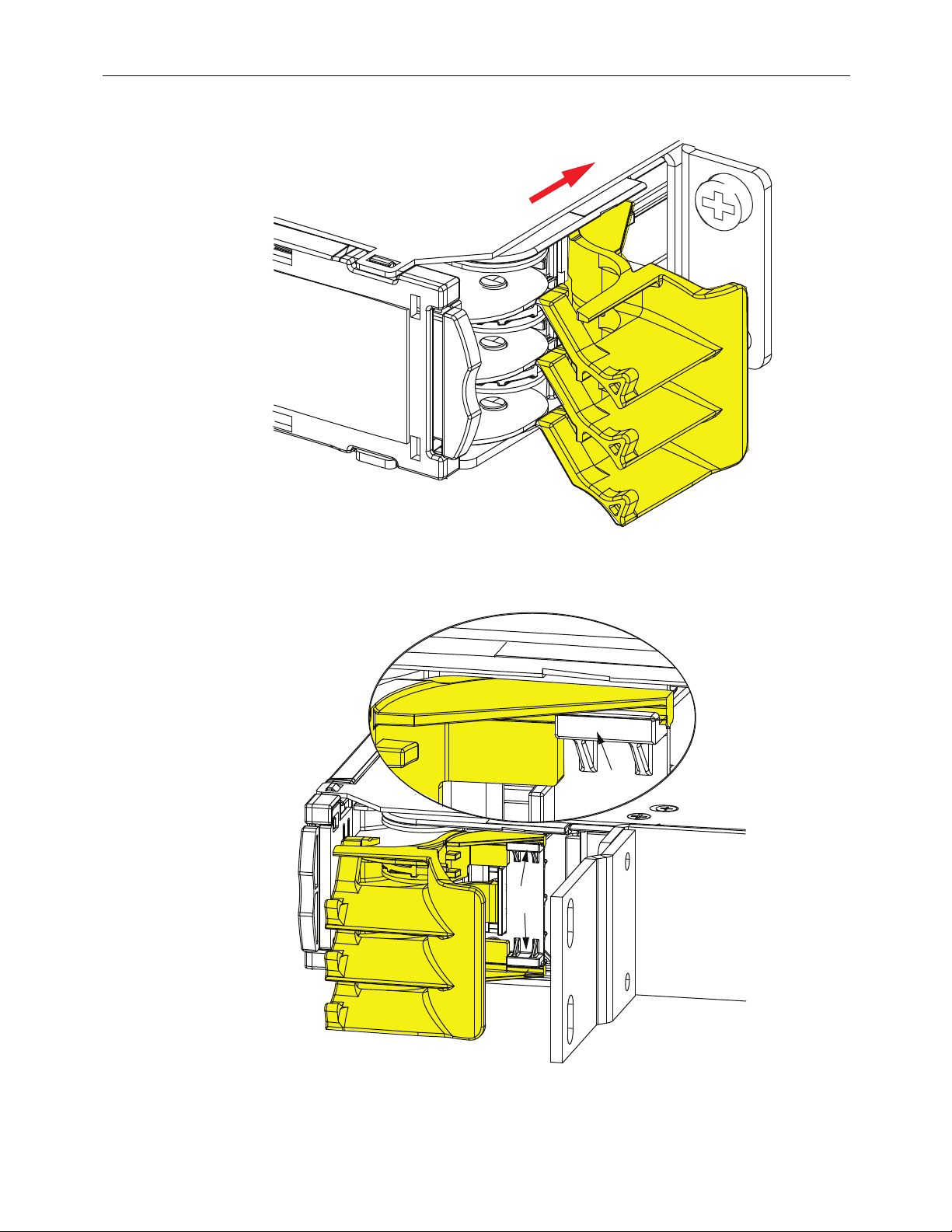
2. Insert the VCG into the panel using the orientation shown in Figure 5.
3. Press the VCG into position in the panel as shown in Figure 6.
Note: Make
sure the leading edge of the VCG is inserted under the guide rails as shown in
Figure 7.
Page 10
© 2017 CommScope. All Rights Reserved.
Page 11

FRONT VIEW
OF FRAME
TECP-90-801 • Issue 4 • October 2017
26575-A
VERTICAL
CABLE
GUIDE (VCG)
Figure 4. Orienting VCG With Panel (Shown Here Without Extension Bracket)
INSERTION POSITION
Figure 5. Inserting VCG in Panel
26576-A
Page 11
© 2017 CommScope. All Rights Reserved.
Page 12
TECP-90-801 • Issue 4 • October 2017
FINAL VCG POSITION
Figure 6. Pressing VCG Into Position
GUIDE
RAILS
GUIDE
RAILS
26577-A
FRAME
NOT
SHOWN
FOR
CLARITY
Page 12
© 2017 CommScope. All Rights Reserved.
25409-A
Figure 7. Make Sure to Insert VCGs Behind Guide Rails
Page 13

3.5 Grounding the Panel
A termination (for a 10-32 screw) is provided on the panel for a frame ground connection. The
connection must be made in accordance with local and national electrical codes.
1. Locate the ground location on the panel. See Figure 8.
2. Using AWG 14 (1.6mm) solid copper wire, secure a crimp lug to one end of the ground
wire
(installer provided). See Figure 8. Secure the crimp lug to panel with one 10-32
screw. Torque the screw to approximately 15 pound-inches (1.7 Newton meters).
TECP-90-801 • Issue 4 • October 2017
Caution:
Reliable earthing of rack-mounted equipment should be maintained. Particular attention
should be given to supply connections other than direct connections to the branch circuit (e.g. use
of power strips).
Note: To assure proper operation, the panel should be connected to a good earth ground.
There must be no switching or disconnecting devices in the grounding circuit conductor
between power source and point of connection to the grounding electrode conductor.
3. Connect the other end of the ground wire to the earth ground conductor. Ensure this
connection is made using methods and hardware that meets all applicable local and
national electrical codes.
Figure 8. HDEP Ground Location
© 2017 CommScope. All Rights Reserved.
Page 13
Page 14

TECP-90-801 • Issue 4 • October 2017
3.6 Installing the Management Unit
To install the Management Unit, refer to the separate instructions provided in TECP-90-805,
provided with the unit or via the QR code on the panel. The management unit contains the panel
controller and memory used to store system settings.
3.7 Connecting the Ethernet Cable and AUX Power Cable
Caution: When connecting the equipment to the power sources, check the equipment nameplate
rating to avoid overloading circuits which may cause damage to over-current protection devices
and supply wiring.
Each panel controller has two potential power sources. One is a Power over Ethernet (
PoE)
source, and the second is AUX power from an external source.
A RJ-45 connection to the panel is required to interface the Ethernet to the end user. Connect an
Ethernet cable to the RJ-45 port. If this connection originates at a PoE switch the panel is powered
over the Ethernet connection.
If only a PoE connection is made to the panel, the PoE connection powers the panel and the AUX
power
connection is not required. If both a PoE switch and an AUX power source connection is
made, the AUX power connection powers the controller. If a standard Ethernet (non PoE)
connection is made to the controller, the AUX power connection is required to power the
controller.
A PoE switch and an AUX power supply can simultaneously be connected. A PoE switch is
designed to shut power off when the presence of another power source (AUX power) is present.
If power is not provided through the AUX port, the controller assumes a PoE switch is the
voltage source. During the AUX power application to the controller, the transition from PoE to
AUX is seamless.
If AUX power is discontinued, there is an interruption of power and communications to the
controller
before power is supplied by the PoE switch. Refer to Management Unit Instructions
(TECP-90-806) for AUX power details.
3.8 Connecting the Control Cable
Connect the wiring to the Ethernet RJ45 jack on the PoE switch. Plug the other end of the
Ethernet cable into the controller at the front of the panel.
The Ethernet port supports a maximum cable length of 328 feet (100 meters) to a switch. Pins 1,
3, and 6 (See Figure 9) are used in 10BASE-T (10Mb/s) and 100BASE-TX (100Mb/s)
2,
networking. Set PoE switch to auto-negotiate, the controller Ethernet port supports 10/100Mb/s.
Page 14
© 2017 CommScope. All Rights Reserved.
Page 15

TECP-90-801 • Issue 4 • October 2017
PIN 1
PIN 8
RJ-JACK
Figure 9. RJ45 Connector Wiring
11899-A
When bringing Ethernet cable into the panel, make sure that cable is run vertically along the left
or right side of the bay. Route Ethernet Cable to the rear of the panel. Secure cable to panel
using tie points provided. Leave enough cable slack to make connection to the appropriate
location on the Controller.
Note: All
Ethernet or PoE cabling should be routed away from any sharp edges and
properly secured in place to prevent chafing and to provide strain relief. This may be
achieved by tie-wrapping the wires to the rack frame or by a similar means.
3.9 Connecting the Panel to the Quareo Network
After the Quareo HDEP has been physically installed on the rack, a software procedure must be
performed to access the panel controller and make the controller known on the Quareo network.
This procedure is done using a web browser to access the configuration web pages of the panel
controller. This can be done at the panel by connecting an ethernet cable from a computer to the
RJ-45 port of panel controller to gain network access to the controller. Once the IP address of
the panel is known, the user can input the address of the panel controller into the web browser to
access the configuration pages.
Instructions for performing the software procedure described above can be found in TECP-90-
which is available on the CommScope website.
805,
4 INSTALLING MODULES AND IFC CABLES
Note: Remove the dust cap, inspect, and clean MPO connector per ADCP-96-150
instructions before terminating. Remove the ferrule dust cap from one of the patch cord
connectors and then clean the connector as specified in the Optical Fiber Connector Wet
and Dry Cleaning Instructions (ADCP-90-159) or by locally approved procedures.
Modules available for use in the Quareo 1RU high density panel include the following:
• LC-LC adapter pack
• MPO-MPO adapter pack
• LC-MPO module
• LC cabled module
© 2017 CommScope. All Rights Reserved.
Page 15
Page 16

TECP-90-801 • Issue 4 • October 2017
In general, all modules are installed by opening the access tray, snapping the module into place
in the access tray, and routing the fiber cables through the access trays. Instructions unique to
the various module types are provided through QR code access to the CommScope Field
Support Link. This online site contains video, animations, and other information for the specific
module being installed.
The QR code is a label on the front of the panel; the Field Support Link is accessed using a
recognition app on a smart phone.
visual
5 TECHNICAL ASSISTANCE
http://www.commscope.com/SupportCenter
Page 16
 Loading...