

Page 1
Installation Instructions
ADCP-92-309
Issue 4, July 2016
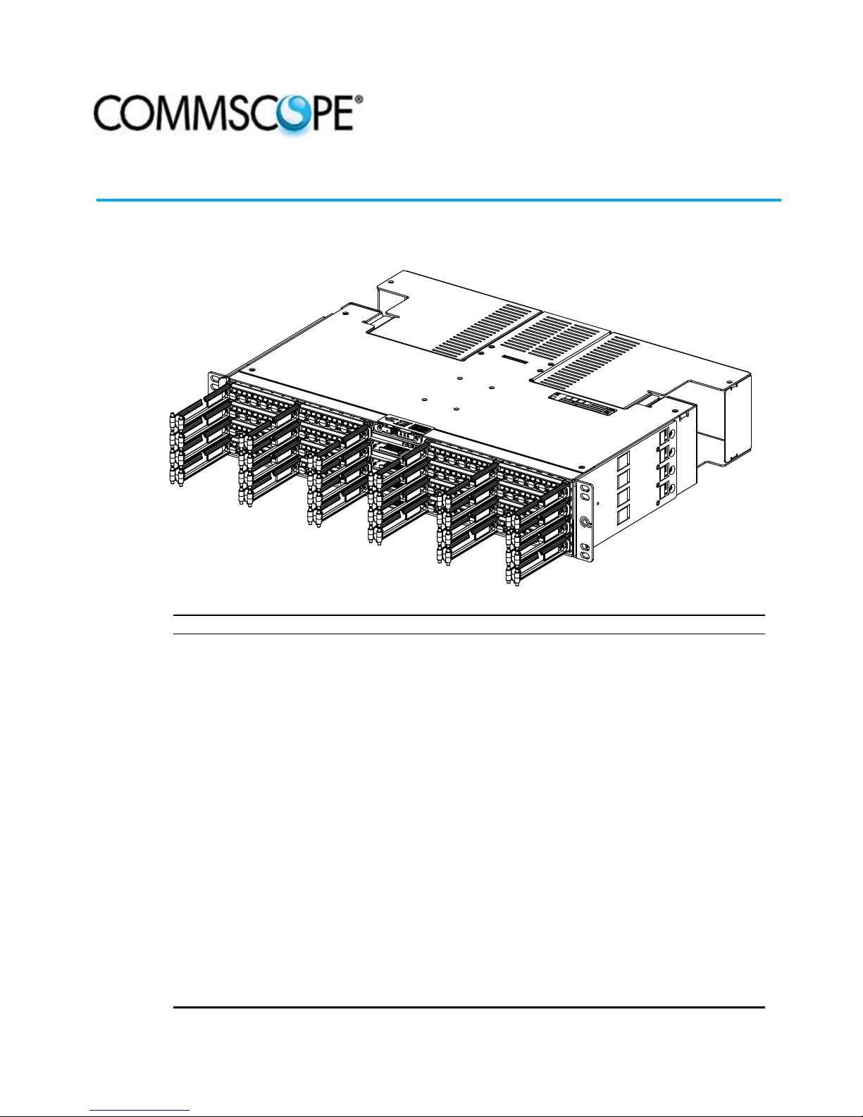
Quareo
Quareo 4000 Network Chassis
24749-A
Content Page
INTRODUCTION . . . . . . . . . . . . . . . . . . . . . . . . . . . . . . . . . . . . . . . . . . . . . . . . . . . . . . . . . . . . . . . . . . . . . . . . . . . . . .2
1 SPECIFICATIONS . . . . . . . . . . . . . . . . . . . . . . . . . . . . . . . . . . . . . . . . . . . . . . . . . . . . . . . . . . . . . . . . . . . . . . . .3
2 UNPACKING AND INSPECTION . . . . . . . . . . . . . . . . . . . . . . . . . . . . . . . . . . . . . . . . . . . . . . . . . . . . . . . . . . . . . . .3
3 CHASSIS INSTALLATION . . . . . . . . . . . . . . . . . . . . . . . . . . . . . . . . . . . . . . . . . . . . . . . . . . . . . . . . . . . . . . . . . . .4
3.1 Rack Installation . . . . . . . . . . . . . . . . . . . . . . . . . . . . . . . . . . . . . . . . . . . . . . . . . . . . . . . . . . . . . . . . . .4
3.2 Quareo Cross-Connect Solution Installation . . . . . . . . . . . . . . . . . . . . . . . . . . . . . . . . . . . . . . . . . . . . . . . .6
3.3 Grounding Chassis . . . . . . . . . . . . . . . . . . . . . . . . . . . . . . . . . . . . . . . . . . . . . . . . . . . . . . . . . . . . . . . . .7
3.4 Power Cabling . . . . . . . . . . . . . . . . . . . . . . . . . . . . . . . . . . . . . . . . . . . . . . . . . . . . . . . . . . . . . . . . . . . .8
3.4.1 AUX Power . . . . . . . . . . . . . . . . . . . . . . . . . . . . . . . . . . . . . . . . . . . . . . . . . . . . . . . . . . . . . . 9
3.4.2 Interface Connection Ethernet Port (RJ45 Connector) PoE Switch . . . . . . . . . . . . . . . . . . . . . . . . . 9
3.5 Blade Installation . . . . . . . . . . . . . . . . . . . . . . . . . . . . . . . . . . . . . . . . . . . . . . . . . . . . . . . . . . . . . . . . . .9
3.6 Cable Installation . . . . . . . . . . . . . . . . . . . . . . . . . . . . . . . . . . . . . . . . . . . . . . . . . . . . . . . . . . . . . . . . .11
3.6.1 LC or MPO Trunk Cable Installation. . . . . . . . . . . . . . . . . . . . . . . . . . . . . . . . . . . . . . . . . . . . . 11
3.6.2 LC Array Cable Installation . . . . . . . . . . . . . . . . . . . . . . . . . . . . . . . . . . . . . . . . . . . . . . . . . . 13
3.6.3 LC Trunk Cable Installation LC to LC Blade . . . . . . . . . . . . . . . . . . . . . . . . . . . . . . . . . . . . . . . 14
3.6.4 MPO Trunk Cable Installation MPO to MPO Blade . . . . . . . . . . . . . . . . . . . . . . . . . . . . . . . . . . . 18
3.6.5 MPO Trunk Cable Installation MPO to LC Blade . . . . . . . . . . . . . . . . . . . . . . . . . . . . . . . . . . . . 22
4 TECHNICAL ASSISTANCE. . . . . . . . . . . . . . . . . . . . . . . . . . . . . . . . . . . . . . . . . . . . . . . . . . . . . . . . . . . . . . . . . .24
300001739168 Rev B Page 1
www.commscope.com © 2016 CommScope. All Rights Reserved.
Page 2
ADCP-92-309 • Issue 4 • July 2016
INTRODUCTION
The Network Chassis is available as a
chassis may be operated as passive chassis, or may become part of a Managed System by
inserting controllers, a network chassis display board, and connecting the Ethernet port. This
document describes the installation of the chassis in a typical rack installation.
Trademark Information
CommScope (logo), CommScope, and Quareo are trademarks
Admonishments
Important safety admonishments are used throughout this manual to warn of possible hazards to
persons or equipment. An admonishment identifies a possible hazard and then explains what
may happen if the hazard is not avoided. The admonishments — in the form of Dangers,
Warnings, and Cautions — must be followed at all times.
Danger: Danger is used to indicate the presence of a hazard that will cause severe personal
injury, death, or substantial property damage if the hazard is not avoided.
Warning: Warning is used to indicate the presence of a hazard that can cause severe personal
injury, death, or substantial property damage if the hazard is not avoided.
2-blade 1RU, 4-blade 2RU, and 8-blade 4RU
.
. The network
Caution: Caution is used to indicate the presence of a hazard that will or can cause minor
personal injury or property damage if the hazard is not avoided.
General Safety Precautions
Warning: To prevent electrical shock, never install chassis in a wet location or during a
lightning storm. When installing or modifying telephone lines, disconnect lines at the network
interface before working with uninsulated lines or terminals.
Caution: When connecting the equipment to the power sources, check the equipment nameplate
rating to avoid overloading circuits which may cause damage to over-current protection devices
and supply wiring.
Caution: If the chassis is installed in a closed or multi-rack assembly, the operating
temperature of the rack environment may be greater than the ambient temperature. Be sure to
install the chassis in an environment that is compatible with the maximum rated ambient
temperature. See Specifications.
Caution: Installation of the equipment in a rack should be such that air f low to the equipmen t is
not compromised.
Page 2
© 2016 CommScope. All Rights Reserved.
Page 3
Caution: When mounting equipment in the rack make sure mechanical loading is even to avoid
a hazardous condition, such as loading heavy equipment in the rack unevenly. The rack should
safely support the combined weight of all equipment it supports.
Caution: Reliable earthing of rack-mounted equipment should be maintained. Particular
attention should be given to supply connections other than direct connections to the branch
circuit (e.g. use of power strips).
Caution: This equipment is to be installed only in Restricted Access Areas (dedicated
equipment rooms, equipment closets, etc.) in accordance with Articles 110-16, 110-17, an d 11018 of the National Electrical Code, ANSI/NFPA 70.
1 SPECIFICATIONS
Specifications for the chassis are listed in Table 1.
ADCP-92-309 • Issue 4 • July 2016
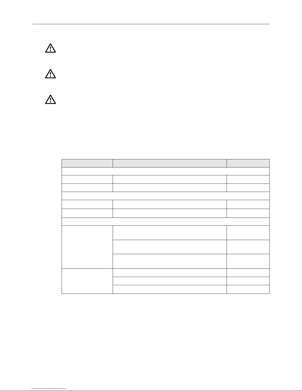
Table 1. Network Chassis Specifications
PARAMETER SPECIFICATION REMARKS
Power
Voltage
Input Current 270mA maximum (per IEEE 802.3af) At 48 VDC
Environmental
Operating Conditions
Storage Conditions
Mechanical
Dimensions D x W x H
Weight 4.1 lb. (1.86 kg.) Empty 1RU chassis
36–57 VDC nominal
+14F to +140F (
10C to +60C)
5% to 95% RH
40F to +158F (40C to +70C) 10% to 95% RH
x
13.35 in (33.9 cm) D
1.7 in (4.32 cm) H
13.35 in (33.9 cm) D
3.45 in (8.73 cm) H
13.35 in (33.9
6.95 in (17.65 cm) H
5.3 lb. (2.40 kg.) Empty 2RU chassis
6.8 lb. (3.08 kg.) Empty 4RU chassis
cm) D x 19.01 in (48.29 cm) W x
19.01 in (48.29 cm) W x
x
19.01 in (48.29 cm) W x
No Condensation
No Condensation
1RU chassis
2RU chassis
4RU chassis
2 UNPACKING AND INSPECTION
Unpack and inspect the various components as follows:
1. Inspect the exterior of the shipping container(s) for evidence of rough handling that may
have damaged the components in the container.
2. Unpack each container while carefully checking the contents for damage and verify with
the packing slip.
© 2016 CommScope. All Rights Reserved.
Page 3
Page 4
ADCP-92-309 • Issue 4 • July 2016
3. If damage is found or parts are missing, file a claim with the commercial carrier and notify
CommScope Customer Service. Save the damaged cartons for inspection by the carrier.
4. Refer to Section 4 Technical Assistance if you need to contact CommScope.
5. Save all shipping containers for use if the equipment requires shipment at a future date.
The following procedures provide the necessary instructions for installing and wiring a chassis
in an equipment rack.
Caution: This equipment is to be installed only in Restricted Access Areas (dedicated
equipment rooms, equipment closets, etc.) in accordance with Articles 110-16, 110-17, an d 11018 of the National Electrical Code, ANSI/NFPA 70.
3 CHASSIS INSTALLATION
Warning: To prevent electrical shock, never install chassis in a wet location or during a
lightning storm. When installing or modifying telephone lines, disconnect lines at the network
interface before working with uninsulated lines or terminals.
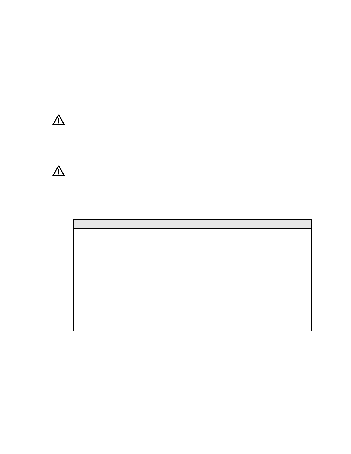
Tool and hardware requirements are listed in Table 2.
CONSIDERATION DESCRIPTION
Tools Needed #1 Phillips Screwdriver,
Rack Mounting 19” EIA/WECO/ETSI Rack Mounting
Grounding Secure chassis to ground. Use #1 Phillips Screwdriver to tighten the 10-32
Incoming IFC Cable
Clamping
3.1 Rack Installation
This procedure provides instructions for installing the chassis in a 19-inch (482.6mm)
equipment rack. Check the work order to determine the chassis location in the rack. Mounting
hardware is shipped loose. Each chassis is secured with either 12-24 screws, M6 hardware, or
®
TrueNet
quick fit hardware depending on the rack used.
Table 2. Installation Tools and Hardware Needs
#2 Phillips Screwdriver
3/16” Standard Screwdriver
Use supplied #12-24 screws and #2 Phillips Screwdriver to secure the chassis
to the rack or cabinet or
Use supplied M6 screws, cage nuts and #2 Phillips Screwdriver to secure the
chassis to the rack or cabinet or
Use TrueNet
screws through the ground lug (provided) into the chassis ground PEM nuts.
Ground cables are NOT provided with the chassis.
Use supplied cable clamps and 3/16” standard screwdriver to secure the
incoming IFC cable.
®
Frame “quick fit” solution.
1. Obtain the following tools and equipment:
• Flat blade or Phillips screwdriver (type to match mounting screws)
Page 4
© 2016 CommScope. All Rights Reserved.
Page 5
ADCP-92-309 • Issue 4 • July 2016
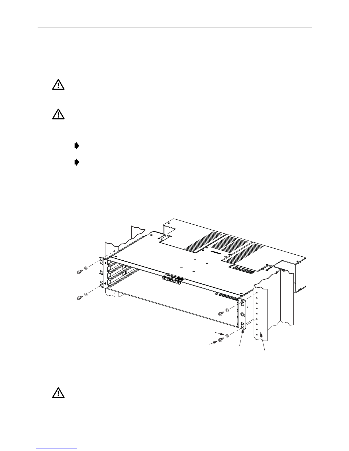
MOUNTING
BRACKET
12-24 x 1/2 IN.
SCREW (4)
24751-A
RACK
FRONT
FLANGE
LOCKWASHER
(4)
• Locate mounting hardware required.
2. Determine what rack size is being used. When installing in a 19-inch rack use the hardware
provided to attach the chassis to the rack.
Caution:
If chassis is installed in a closed or multi-rack a ssembly, the operating temp erature of the
rack environment may be greater than the ambi ent tempe rature. B e sure to i nstall the chass is in an
environment that is compatible with the maxim um ra ted amb ient t emp eratu re. See Sp ecif icatio ns.
Caution: Installation of the equipment in a rack should be such that air f low to the equipmen t is
not compromised.
3. Locate the equipment rack mounting space that is specified for the chassis.
Note: Ethernet cabling distance to and from the chassis should not exceed 328ft. (100m).
Note: If installing chassis in a Q-Frame (Cross-Connect Solution), make ground
connection to chassis before securing chassis in the rack.
4. Place chassis in the assigned mounting space and align the holes in the mounting brackets
with the holes in the equipment rack. See Figure 1.
5. Secure chassis to equipment rack using the appropriate hardware. Torque these screws to
approximately 27 pound-inches (3.1 Newton meters).
Caution: When mounting equipment in the rack make sure mechanical loading is even to avoid
a hazardous condition, such as loading heavy equipment in the rack unevenly. The rack should
safely support the combined weight of all equipment it supports.
Figure 1. Installing 2RU Chassis
© 2016 CommScope. All Rights Reserved.
Page 5
Page 6
ADCP-92-309 • Issue 4 • July 2016
FRONT VIEW
24732-A
1
2
3
4
5
6
7
8
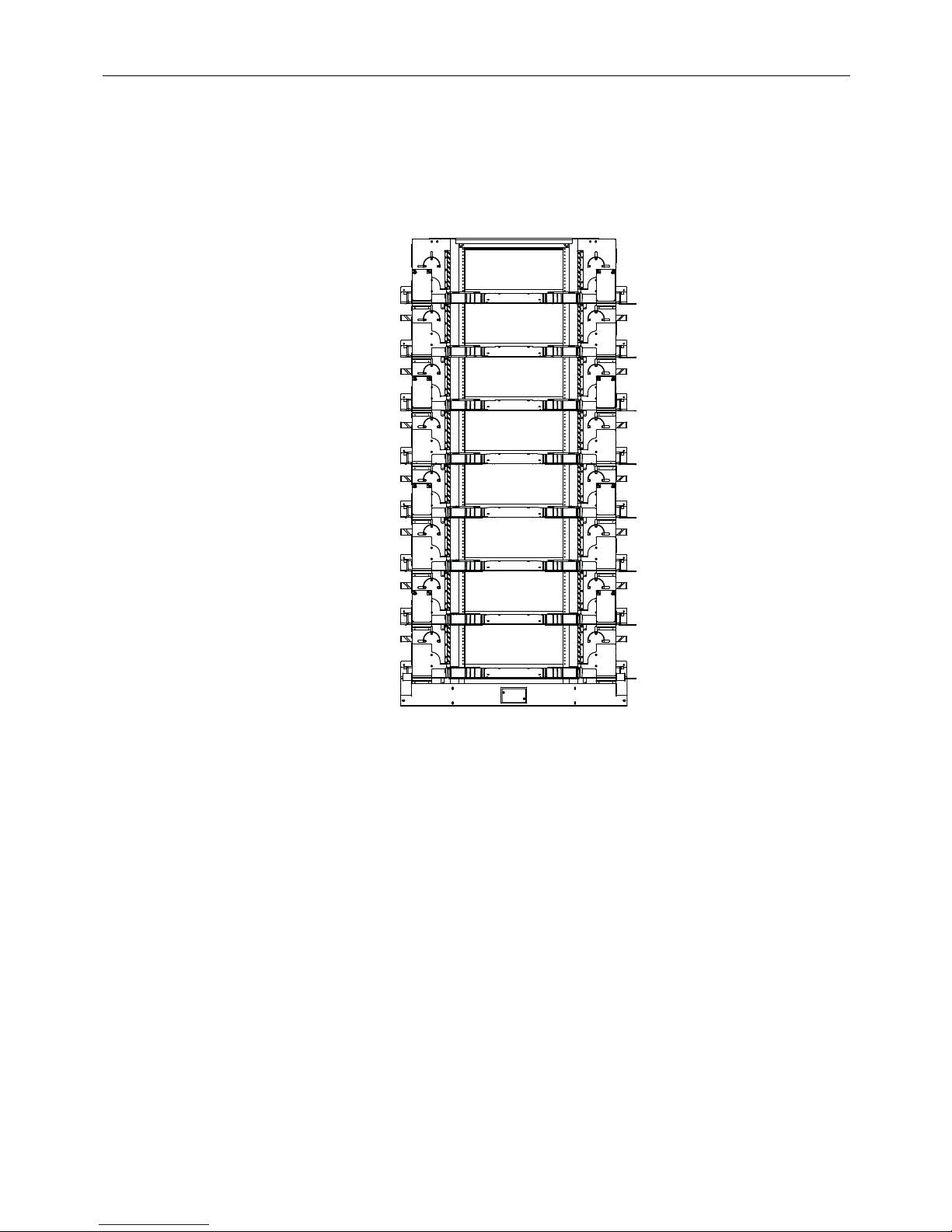
3.2 Quareo Cross-Connect Solution Installation
In the Quareo cross-connect solution frame there are eight spaces for mounting network chassis.
Consider them to be numbered one through eight starting at the top, see Figure 2.
Page 6
© 2016 CommScope. All Rights Reserved.
Figure 2. Quareo Cross-Connect Solution Frame
Page 7
ADCP-92-309 • Issue 4 • July 2016
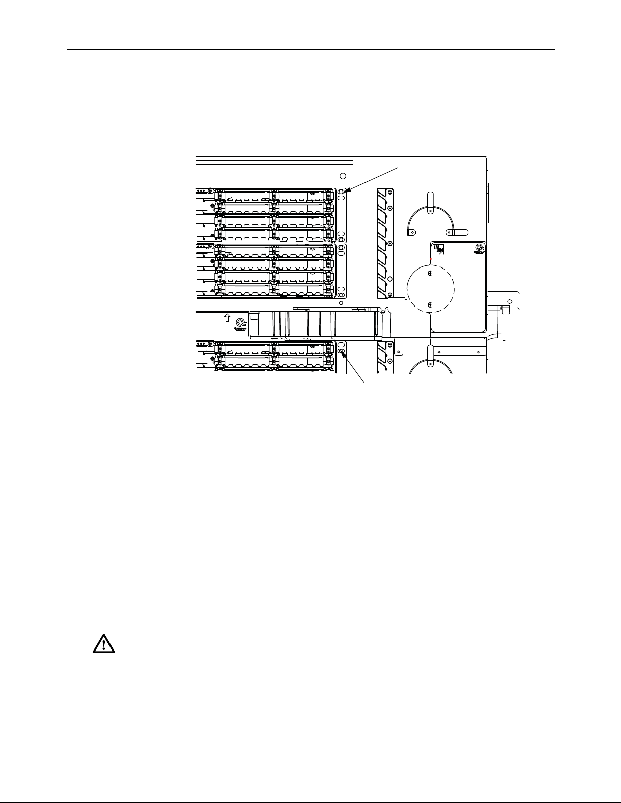
CHASSIS
MOUNTING
SCREW
SPACE
2
24731-A
SPACE
1
CHASSIS
MOUNTING
SCREW
When installing Quareo Network Chassis in the odd spaces (1, 3, 5, 7) the first chassis in each
space is secured using the top mounting hole in the chassis and the lowest hole in chassis. When
installing Quareo Network Chassis in the even spaces (2, 4, 6, 8) the first chassis in each space is
secured using the second mounting hole in the ch assis and the lowe st hole in ch assis. See
Figure 3
.
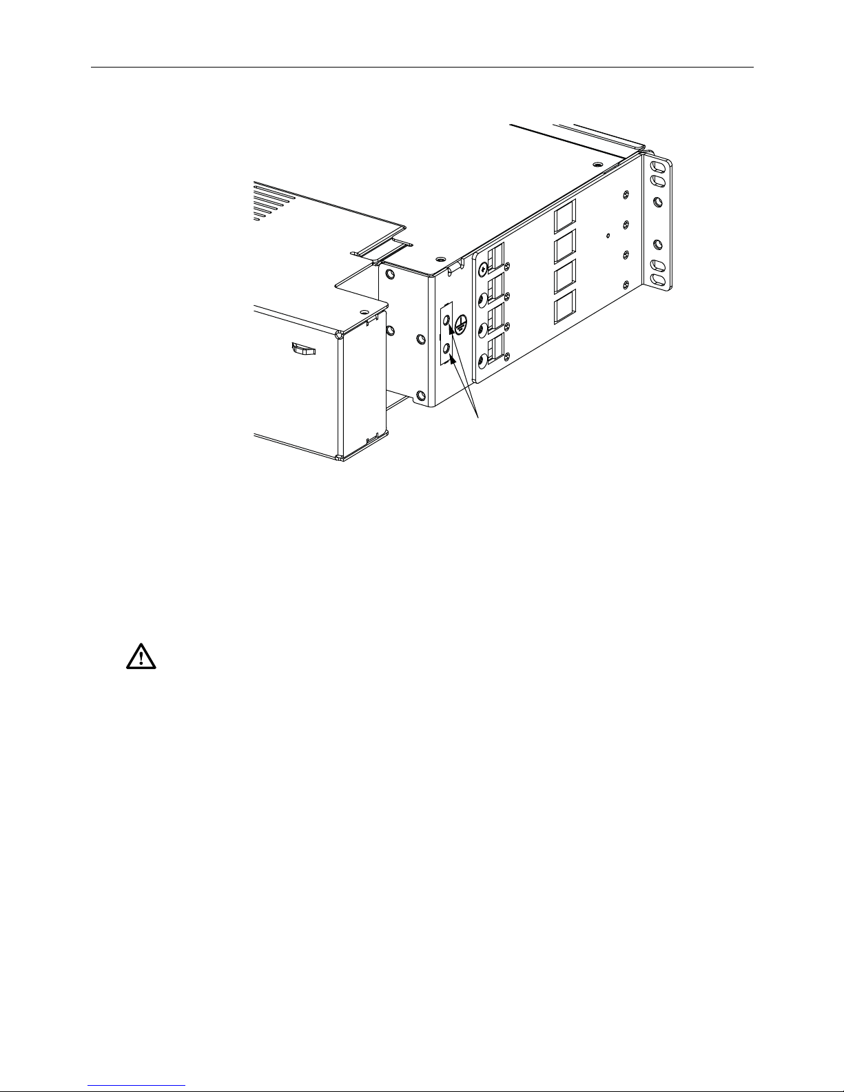
3.3 Grounding Chassis
This procedure establishes a ground connection between the chassis and the earth ground
connection. Frame ground terminations (10-32 screws) are provided on the chassis, for a frame
ground connection. This connection must be made in accordance with all local and national
electrical codes.
1. Locate ground location on chassis, see Figure 4. At grounding location remove protective
tape from chassis.
2. Using AWG 14 (1.6mm) solid copper wire, secure two hole ground lug to one end of the
ground wire (installer provided). Secure ground lug to chassis with two 10-32 screws.
Torque ground screws to approximately 15 pound-inches (1.7 Newton meters).
Caution:
should be given to supply connections other than direct connections to the branch circuit (e.g. use
of power strips).
3. To assure proper operation the chassis should be connected to a good earth ground. There
Reliable earthing of rack-mounted equipment should be maintained. Particula r attention
must be no switching or disconnecting devices in the grounding circuit conductor between
the power source and the point of connection to the grounding electrode conductor.
Figure 3. Network Chassis Mounting Hole Location
© 2016 CommScope. All Rights Reserved.
Page 7
Page 8
ADCP-92-309 • Issue 4 • July 2016
24739-A
GROUND
LOCATION
4. Connect the other end of the ground wire to the earth ground conductor. Ensure this
connection is made using methods and hardware that meets all applicable local and
national electrical codes.
3.4 Power Cabling
Caution: When connecting the equipment to the power sources, check the equipment nameplate
rating to avoid overloading circuits which may cause damage to over-current protection devices
and supply wiring.
Each chassis controller has two potential power sources. One is a Power over Ethernet (
source, and the second is AUX power from an external source.
A RJ-45 connection on the controller is requi red to inte rface the Et hernet to the end user . Connec t
an Ethernet cable to the RJ-45 port. If this connection originates at a PoE switch the controller is
powered over the Ethernet connection. If on ly a PoE connecti on is made to the controller, the PoE
connection powers the controller. The AUX power connection is not required for power. If both a
PoE switch and an AUX power source connection is made to the controller, the AUX power
connection powers the controller. If a standard Ethernet (non PoE) connection is made to the
controller, the AUX power connection is required to po wer the controller.
Figure 4. 2RU Chassis Ground Location
PoE)
A PoE switch and an AUX power supply can simultaneously be connected to the controller
module. A PoE switch is designed to shut power off when the presence o f another p ower source
(AUX power) is present. If power is not provided through the AUX port the controller assumes
a PoE switch is the voltage source. During the AUX power application to the controller the
Page 8
© 2016 CommScope. All Rights Reserved.
Page 9

ADCP-92-309 • Issue 4 • July 2016
RJ-JACK
PIN 1
PIN 8
11899-A
transition from PoE to AUX is seamless. If AUX power is discontinued there is an interruption
of power and communications to the controller before power is supplied by the PoE switch.
3.4.1 AUX Power
Refer to Chassis Controller Installation Instructions (ADCP-92-311) for AUX power details.
3.4.2 Interface Connection
Ethernet Port (RJ45 Connector) PoE Switch
Connect the wiring to the Ethernet RJ45 jack on the PoE switch. Plug the other end of the
Ethernet cable into the controller at the back of the chassis. The Ethernet port supports a
maximum cable length of 328 feet (100 meters) to a switch. Pins 1, 2, 3, and 6 (See Figure 5)
are used in 10BASE-T (10Mb/s) and 100BASE-T (100Mb/s) networking. Set PoE switch to
auto-negotiate, the controller Ethernet port supports 10/100Mb/s.
Figure 5. RJ45 Connector Wiring
When bringing Ethernet cable into the chassis, make sure that cable is run vertically along the
left or right side of the bay. Route Ethernet Cable to the rear of the chassis. Secure cable to
chassis using tie points provided. Leave enough cable slack to make connection to the
appropriate location on the Controller.
Note: All Ethernet or PoE cabling should be routed away from any sharp edges and
properly secured in place to prevent chafing and to provide strain relief. This may be
achieved by tie-wrapping the wires to the rack frame or by a similar means.
3.5 Blade Installation
Several single-mode or multimode blades are available for installation in the network chassis.
They are LC-to-MPO, LC-to-LC, and MPO-to-MPO. For cable clamping and management
reasons mixing of fiber cable fanout types in a single chassis is not recommended. A blank
cover (Catalog # QBCB-HR), one per slot is available to fill unused slots in the chassis. Blade
slots are numbered at the left side of chassis, starting with one at the top.
Note: Remove dust cap, inspect, and clean MPO connector per ADCP-96-150 instructions
before terminating. Remove the ferrule dust cap from one of the patch cord connectors and
then clean the connector as spe cified in the Optical Fiber Connector Wet and Dry Cleaning
Instructions (ADCP-90-159) or by locally approved procedures.
© 2016 CommScope. All Rights Reserved.
Page 9
Page 10

ADCP-92-309 • Issue 4 • July 2016
MODULES FULLY
INSERTED
MODULE
AT 3-INCH
DETENT
MODULE
AT 6-INCH
DETENT
24752-A
When the blade is fully pushed into the chassis it is connected to the back plane. The blade
remains connected to the back plane at the first detente position. When the blade is pulled out to
the second detent the blade is disconnected from the back plane. When the blade is fully pushed
into the chassis it is reconnected. Refer to
Figure 6
.
Figure 6. Fiber Blade Detents
Install blades starting at the bottom, filling the remaining slots until the chassis is full.
1. Align
blade
edges with slot in chassis and slide into chassis from the front.
2. Blade will snap into the chassis when it is inserted about half way.
3. Press in on the Latches on each side of the
4. Push in on second set of latches and push
blade
and push in to next detent.
blade
all the way into the chassis.
5. When blade is pushed all the way into the chassis it is connected to the back plane.
6. Route incoming fibers to chassis. See Section 3.6 Cable Installation.
a. If Managed Fiber Cables are used attach cables to appropriate adapters.
b. If LC to MPO blades are used attach MPO cables to appropriate adapters.
7. Make sure to route the Managed Fiber Cables right or left as determined by the side of the
chassis the cables are entering from. Route Managed Fiber Cables through cable
management system to the front of the chassis and attach to proper adapters.
Caution: If blades are in one of the detent positions when fiber connections are made, make
certain that there is enough slack in the cable so that when blade is pushed in fiber bend radius
is not compromised.
Page 10
© 2016 CommScope. All Rights Reserved.
Page 11

8. Install blank covers in unused slots by placing the right end into the recess on the right side
of the chassis, then push the left end (latch) into the left side of the slot. Remove blank
cover by sliding latch to the right and lifting cover out of the chassis.
Blade removal is the reverse of installation. Make certain that all data passing through a blade is
rerouted before beginning the removal process.
3.6 Cable Installation
Note: Remove the dust cap, inspect, and clean MPO connector per ADCP-96-150
instructions before terminating. Remove the ferrule dust cap from one of the patch cord
connectors and then clean the connector as specified in the Optical Fiber Connector Wet
and Dry Cleaning Instructions (ADCP-90-159) or by locally approved procedures.
Each fiber breakout should be secured to the rack above or below the chassis. Trunk cables enter
the chassis from the side near the rear. The method and location for securing the trunk cable is
dependent upon the cable type.
ADCP-92-309 • Issue 4 • July 2016
LC to LC Blade –
Secure individual fanouts to the rear of the blade or chassis using the retaining
clip or O-rings provided. Route trun k cable s fo r m ulti ple bla des into ch ass is at the re ar and sec ure
with hardware provided.
MPO to LC Blade –
Secure individual fanouts to the rear of the blade or chassis using the
retaining clip or O-rings provided. Route trunk cables for multiple blades into chassis at the rear
and secure with hardware provided.
MPO to MPO Blade –
Route trunk cable for multiple blad es through the grommets at the rear of
chassis and secure with hardware prov ided.
Some blades use Mille-Ties to secure cables to the sliding blade cable tie clip. Some LC to LC
blades use a fanout retainer and blade cable cover to hold fibers in place. From the tie point, the
optical fibers are routed to the adapters at the front of the blade.
Use procedure
Cable Installation
Use procedure
Trunk Cable Installation MPO to MPO Blade
MPO to LC Blade
Section 3.6.1 LC or MPO Trunk Cable Installation
when blade has the cable tie clip.
or
Section 3 .6.2 LC Array
Section 3.6.3 LC Trunk Cable Installation LC to LC Blade, Section 3.6.4 MPO
, or
Section 3.6.5 MPO Trunk Cable Installation
for blades without cable tie clip.
3.6.1 LC or MPO Trunk Cable Installation
When using trunk cables the fiber breakout is normally secured to the rack above or below the
chassis. A grommet or fanout secures the cables at the chassis entry point. From the entry point,
the optical fibers are routed to the adapters at the front of the blade.
Use the following procedure to install cable when blade has the cable tie clip:
1. Locate the cable entry location that is specified for cable installation as shown in Figure 7.
© 2016 CommScope. All Rights Reserved.
Page 11
Page 12

ADCP-92-309 • Issue 4 • July 2016
2. Route cables to chassis securing cables to rack per local practices.
3. Assemble grommets and cable clamps on fiber cables as shown in Figure 7.
CABLE TIE
8-INCH
(20 CM)
SERVICE
LOOP
SCREWS
CLIP
COVER
PLATE
CABLE
CLAMP
USE GROMMET FOR
SMALLER NUMBER
OF CABLES
24753-B
Figure 7. Cable Clamp Installation (LC to MPO Connector)
4. Cable clamps and several grommets are provided with the cable clamp kit for securing
cables to the chassis. More than one grommet may be needed to secure cables in the clamp.
5. Adjust cables leaving an 8-inch (20 cm) service loop within the chassis, this allows blades to
be withdrawn. Tighten compression fitting screw s to secur e cables a t the cable e ntry location .
6. Connect cables to the back of the blade:
a. Leave blade fully inserted in the chassis when connecting MPO connectors to MPO to
LC adapters.
b. Before connecting MPO connectors to MPO to MPO adapters pull blade out to the
second detent.
7. Use Mille-Ties to secure cables to cable tie clip. See Figure 8. Use Mille-Ties to bundle
cables together as necessary.
8. Close blade after installing Mille-Ties.
Page 12
© 2016 CommScope. All Rights Reserved.
Page 13

CABLE TIE
CLIP
MILLE-TIES
ADCP-92-309 • Issue 4 • July 2016
FIBER
FANOUT
24754-B
8-INCH
(20 CM)
SERVICE
LOOP
CABLE
CLAMPS
Figure 8. Cable Installation (MPO to MPO Connector)
3.6.2 LC Array Cable Installation
When using array cables the fiber fanout is normally secured to the chassis with retainers.
Mille-Ties are used to secure the cables to the sliding blade. From the tie point, the optical fibers
are routed to the adapters at the front of the blade.
Use the following procedure to install cable when blade has the cable tie clip:
1. Locate the cable entry location that is specified for cable installation as shown in Figure 9.
Note: To prevent cable congestion install blades and related fiber fanouts starting at the
bottom of the chassis working up the chassis until all slots are filled.
2. Route cables to chassis securing cables to rack per local practices.
3. Adjust cables leaving an 8-inch (20 cm) service loop within the chassis that allows blades
to be withdrawn.
4. Before connecting fibers to adapters pull blade out to the second detent.
5. Slide fiber fanout onto posts on chassis. After installing the last fiber fanout slide a fanout
retainer over each post.
6. Use Mille-Ties to secure cables to cable tie clip. See Figure 9. Use Mille-Ties to bundle
cables together as necessary.
7. Close blade after installing Mille-Ties.
© 2016 CommScope. All Rights Reserved.
Page 13
Page 14

ADCP-92-309 • Issue 4 • July 2016
CABLE TIE
MILLE-TIES
FIBER
FANOUT
24754-B
CLIP
8-INCH
(20 CM)
SERVICE
LOOP
CABLE
CLAMPS
Figure 9. LC Array Cable Installation
3.6.3 LC Trunk Cable Installation LC to LC Blade
When using trunk cables the fiber breakout is normally secured to the rack above or below the
chassis. A grommet fitting secures the cables at the chassis entry point. From the grommet, the
optical fibers are routed to the adapters at the front of the blade. A clip is installed on the rear of
the blade to secure fanout to the blade. Use the following procedure to install the cable:
1. Locate the cable entry location that is specified for cable installation.
Note: To prevent cable congestion install blades and related fiber fanouts starting at the
bottom of the chassis working up the chassis until all slots are filled.
2. Route cables to chassis securing cables and breakout to rack per local practices.
3. Assemble grommets and cable clamps on fiber cables as shown in Figure 10.
Page 14
© 2016 CommScope. All Rights Reserved.
Page 15

ADCP-92-309 • Issue 4 • July 2016
24905-A
USE GROMMET FOR
SMALLER NUMBER
OF CABLES
SCREWS
COVER
PLATE
CABLE
CLAMP
8-INCH
(20 CM)
SERVICE
LOOP
FIBER
COVER
24914-A
Figure 10. Cable Clamp Installation
4. Cable clamps and several grommets are provided with the cable clamp kit for securing
cables to the chassis. More than one grommet may be needed to secure cables in the clamp.
5. Remove cable covers from blades by sliding towards the rear of the blade and lifting out of
the retaining slot. See Figure 11.
Figure 11. Fiber Cover Removal
© 2016 CommScope. All Rights Reserved.
Page 15
Page 16

ADCP-92-309 • Issue 4 • July 2016
6. Place fanouts into retaining positions on rear of blade. Secure fanouts to blade with clips
provided. See
8-INCH
(20 CM)
SERVICE
LOOP
FANOUT
Figure 12
FANOUT
CLIP
for clip installation.
FIBER
BREAKOUT
24916-A
CABLE
CLAMPS
MILLE-TIES
Figure 12. Fanout Clip Installation
Page 16
© 2016 CommScope. All Rights Reserved.
Page 17

ADCP-92-309 • Issue 4 • July 2016
7. Adjust cables leaving an 8–inch (20 cm) service loop within the chassis, this allows blades
to be withdrawn. See Figure 13. Tighten compression fitting screws to secure cables at the
cable entry location.
FIBER
BREAKOUT
FANOUT
24917-A
8-INCH
(20 CM)
SERVICE
LOOP
CABLE
CLAMPS
MILLE-TIES
Figure 13. Cable Installation
Caution: Always allow sufficient fiber length to permit routing without severe bends. Non bendoptimized fibers may be permanently damaged if bent/curved to a radius of less than 1.5 in.
(3.81 cm).
8. Connect cables to the back of the adapters:
a. Pull blade out to the second detent.
b. Route fibers from the fanout to the adapters.
c. Remove the ferrule dust cap from one of the patch cord connectors and then clean the
connector as specified in the Optical Fiber Connector Wet and Dry Cleaning
Instructions (ADCP-90-159) or by locally approved procedures.
d. Insert connector into the adapter.
e. While holding fibers in place slide blade cover into slot. Pull cover to the front of the
blade and latch in place. See Figure 14.
9. Close blade.
© 2016 CommScope. All Rights Reserved.
Page 17
Page 18

ADCP-92-309 • Issue 4 • July 2016
LC
CONNECTORS
FANOUTS
24915-A
3.6.4 MPO Trunk Cable Installation MPO to MPO Blade
When using trunk cables the fiber breakout is normally secured to the rack above or below the
chassis. A grommet fitting secures the cables at the chassis entry point. From the grommet, the
optical fibers are routed to the adapters at the front of the blade. Use the following procedure to
install the cable:
1. Locate the cable entry location that is specified for cable installation.
2. Route cables to chassis securing cables and breakout to rack per local practices.
3. Assemble grommets and cable clamps on fiber cables as shown in Figure 15.
4. Cable clamps and several grommets are provided with the cable clamp kit for securing
cables to the chassis. More than one grommet may be needed to secure cables in the clamp.
Page 18
© 2016 CommScope. All Rights Reserved.
Figure 14. Fiber Placement on Blade
Page 19

ADCP-92-309 • Issue 4 • July 2016
24905-A
USE GROMMET FOR
SMALLER NUMBER
OF CABLES
SCREWS
COVER
PLATE
CABLE
CLAMP
8-INCH
(20 CM)
SERVICE
LOOP
Figure 15. Cable Clamp Installation
Caution: Always allow sufficient fiber length to permit routing without severe bends. Non bendoptimized fibers may be permanently damaged if bent/curved to a radius of less than 1.5 in.
(3.81 cm).
5. Connect cables to the back of the adapters:
a. Pull blade out to the second detent.
b. Remove dust cap, inspect, and clean MPO connector per ADCP-96-150 instructions
before terminating.
c. Insert connectors into the adapters.
© 2016 CommScope. All Rights Reserved.
Page 19
Page 20

ADCP-92-309 • Issue 4 • July 2016
24918-A
CABLE
CLAMP
8 MPO
CABLES
8-INCH
(20 CM)
SERVICE
LOOP
MILLE-TIES
FIBER
BREAKOUT
d. Route fibers between lances at the rear of the blade. Use a Millie-Tie to secure fibers
to the blade. See Figure 16.
Figure 16. Cable Placemen t
Page 20
© 2016 CommScope. All Rights Reserved.
Page 21

ADCP-92-309 • Issue 4 • July 2016
24919-A
CABLE
CLAMP
8 MPO
CABLES
8-INCH
(20 CM)
SERVICE
LOOP
MILLE-TIES
FIBER
BREAKOUT
6. Adjust cables leaving an 8–inch (20 cm) service loop within the chassis, this allows blades
to be withdrawn. See Figure 17. Tighten compression fitting screws to secure cables at the
cable entry location. Use a Millie-Tie to bundle fibers together.
Figure 17. Cable Installation
© 2016 CommScope. All Rights Reserved.
Page 21
Page 22

ADCP-92-309 • Issue 4 • July 2016
24905-A
USE GROMMET FOR
SMALLER NUMBER
OF CABLES
SCREWS
COVER
PLATE
CABLE
CLAMP
8-INCH
(20 CM)
SERVICE
LOOP
3.6.5 MPO Trunk Cable Installation MPO to LC Blade
When using trunk cables the fiber breakout is normally secured to the rack above or below the
chassis. A grommet fitting secures the cables at the chassis entry point. From the grommet, the
optical fibers are routed to the adapters at the front of the blade. Use the following procedure to
install the cable:
1. Locate the cable entry location that is specified for cable installation.
2. Route cables to chassis securing cables and breakout to rack per local practices.
3. Assemble grommets and cable clamps on fiber cables as shown in Figure 18.
4. Cable clamps and several grommets are provided with the cable clamp kit for securing
cables to the chassis. More than one grommet may be needed to secure cables in the clamp.
Caution: Always allow sufficient fiber length to permit routing without severe bends. Non bendoptimized fibers may be permanently damaged if bent/curved to a radius of less than 1.5 in.
(3.81 cm).
5. Connect cables to the back of the adapters:
6. Remove dust cap, inspect, and clean MPO connector per ADCP-96-150 instructions
Page 22
© 2016 CommScope. All Rights Reserved.
before terminating.
Figure 18. Cable Clamp Installation
Page 23

ADCP-92-309 • Issue 4 • July 2016
24920-A
CABLE
CLAMPS
8-INCH
(20 CM)
SERVICE
LOOP
MILLE-TIES
MPO
CONNECTOR
FIBER
BREAKOUT
7. Adjust cables leaving an 8–inch (20 cm) service loop within the chassis, this allows blades
to be withdrawn. See Figure 19. Tighten compression fitting screws to secure cables at the
cable entry location. Use a Millie-Tie to bundle fibers together.
Figure 19. Cable Installation
Complete chassis installation by installing controllers, chassis status board, and connecting
Ethernet port to the chassis controller. Refer to appropriate installation instructions for complete
details.
© 2016 CommScope. All Rights Reserved.
Page 23
Page 24

ADCP-92-309 • Issue 4 • July 2016
4 TECHNICAL ASSISTANCE
Contact the Technical Assistance Center (TAC) for technical question. Call 800.830.5056 or
send an email to TAC.Americas@commscope.com.
Page 24
Page 25

ADCP-92-309 • Issue 4 • July 2016
© 2016 CommScope. All Rights Reserved.
Page 25
 Loading...