

Page 1

Installation Instructions
TC-1426-IP
Ver 00, Issue 03, May 2019
www.commscope.com
OFDC-B8G
OUTDOOR FIBER DISTRIBUTION CLOSURE
Contents
1 General product information ������������������������������������������������ 1
2 Product image������������������������������������������������������������������������� 1
3 Warnings and caution ������������������������������������������������������������ 2
4 Kit content ������������������������������������������������������������������������������� 2
5 Closure preparation ���������������������������������������������������������������� 2
6 Feeder cable installation �������������������������������������������������������� 3
6.1 Feeder cable preparation ......................................................................... 3
6.2 Feeder cable installation ........................................................................... 3
6.3 Feeder cable ber routing ........................................................................ 3
7 Install branch cable ���������������������������������������������������������������� 4
8 Install organizer in housing ��������������������������������������������������� 4
1 General product information
The OFDC-B8G is the environmentally sealed enclosure for ber management system that provides the function of splicing
(66 splices and for repair up to 90) / patching and passive component integration in the external network.
The closure is sealed with gel for longitudinal seal and wrap around gel block for cable sealing (IP68) 2m water head.
The organizer is fully removable from the closure body and the addition of customers is transient free.
9 Install Drop cables (spliced) ��������������������������������� 5
9.1 Installing 1 cable per drop port ............................................................... 5
9.2 Installing 2 cables per drop port ............................................................ 6
10 Install Connectorized drop cable ������������������������������������������ 7
11 Install TAP’s/Splitters ������������������������������������������������������������� 7
12 Extra features �������������������������������������������������������������������������� 7
13 Mounting options������������������������������������������������������������������� 8
14 Overview of possibilities �������������������������������������������������������� 8
15 Trade-marks ��������������������������������������������������������������������������� 8
16 Contact information ��������������������������������������������������������������� 8
Cable diameters: 2 main cables: 11.5-15 mm
2 branch cables: 8-11 mm
8/16 drop cables: 0-5.5 mm
2 Product image
660003357
Rev. A
© 2019 CommScope, Inc. All Rights Reserved
Page 1 of 8
Page 2

3 Warnings and caution
3.1 Fiber optic cables may be damaged if bent or
curved to a radius that is less than the recommended
minimum bend radius. Always observe the recommended
bend radius limit when installing ber optic cables and patch
cords.
3.2 Exposure to laser radiation can seriously damage
the retina of the eye. Do not look into the ends of any optical
ber. Do not assume the laser power is turned o or that the
ber is disconnected at the other end.
5 Closure preparation
4 Kit content
The kit content is dierent for the patch application and
splice application:
4�1 SPLICE APPLICATION
(66 splices)
5.1 Open the closure by lifting the latches using a
screw driver.
4�2 PATCH APPLICATION
(66 splices + 8/16 Patch points)
5.2 Install the 2 screws (1-2 turns) and the wedge (If
needed).
Page 2 of 8
© 2019 CommScope, Inc. All Rights Reserved
5.3 Slide the gel block on to the organizer. Verify the
correct orientation: Head of the screw facing upwards.
Page 3

6 Feeder cable installation
(11�5-15 mm)
6�1 Feeder cable preparation
6.1.1 Make a window cut of 2m.
6�2 Feeder cable installation
6.2.1 Open the gel block.
45 mm
6.1.2 Cut the strength members at 45 mm from the
jacket end.
6.1.3 Install the cables to the metal bracket as shown.
Secure the cable with a hose clamps at the cable jacket (use a
piece of foam if the cable has a soft jacket). Secure the strength
members or aramid yarn with the metal plate and screw.
6.2.2 Install the assembly to the organizer (snap t at
both sides). Make sure that the ber bundles are free.
6�3 Feeder cable ber routing
6.3.1 Take out the ber tubes to be used and store the
remaining loops as shown. (Secure with cable ties)
6.3.2 Install blind plugs in the unused port(s) and close
the gel block with the top gel part.
© 2019 CommScope, Inc. All Rights Reserved
Page 3 of 8
Page 4
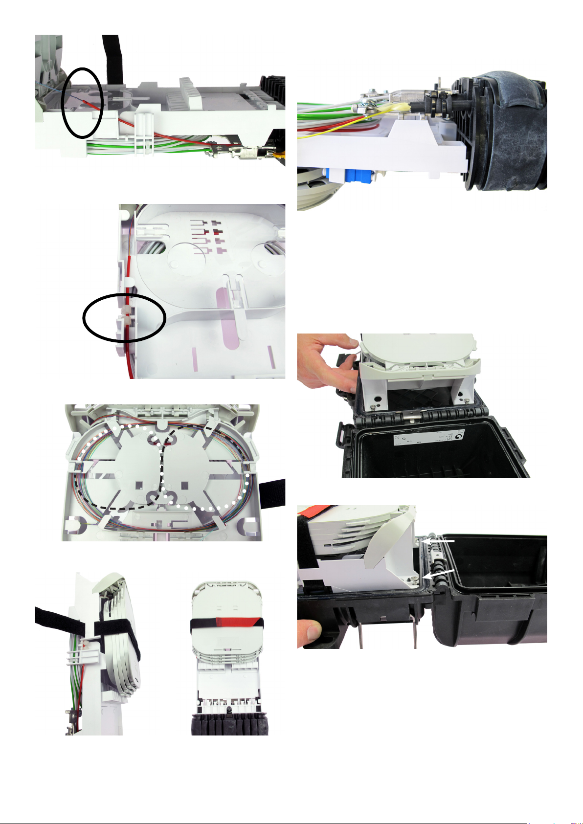
6.3.3 Strip the tube at 15 cm from the jacket end and
clean the bers before routing them to the tray.
7 Install branch cable (8-11 mm)
7.3.1 Remove the jacket over a length of 1 m (or 2 m if
window cut). Prepare the cable jacket with a piece of foam
and secure it with cable ties as shown.
7.3.2 Secure the strength member (35 mm) or aramid
yarn with the metal plate and screw.
7.3.3 Route the ber bundle and bers the same way as
for the main cable. (See section 6.3)
8 Install organizer in housing
6.3.4 Secure the loose tube with 2 cable ties as shown.
6.3.5 Store the bers on the tray. Changing direction is
possible with gure 8, see picture above.
8.1 Install the organizer in the housing as shown. Bring
in under an angle of 45°.
8.2 Tighten the 2 top screws.
6.3.6 Secure the trays as shown.
Page 4 of 8
© 2019 CommScope, Inc. All Rights Reserved
Page 5
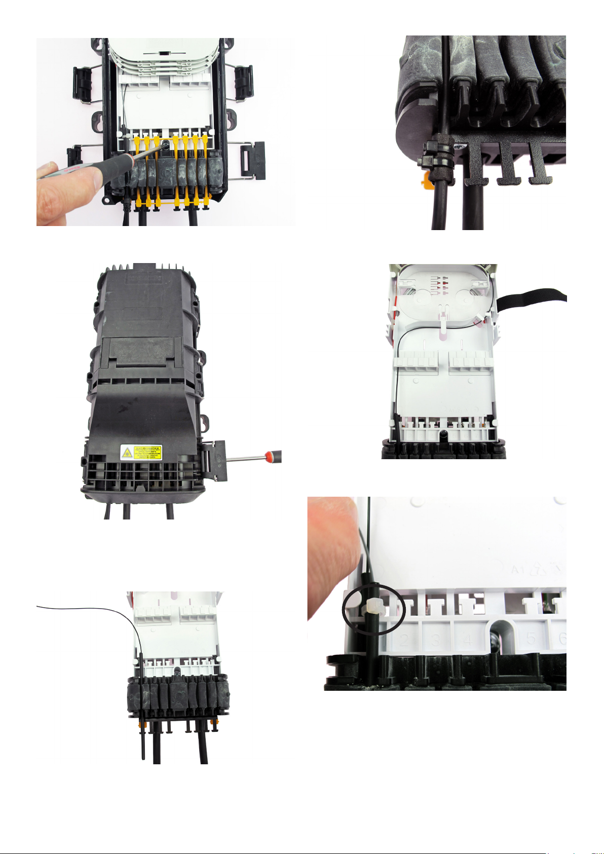
8.3 Tighten the bottom screw and install blind plugs in
the unused ports.
9.1.2 Install a wrap of foam at 80 mm from the jacket
end and secure the cable with 2 cable ties.
9.1.3 Route the ber(s) bundle to splice tray trough the
adapter holder.
8.4 Close the 6 hinges using a screw driver.
9 Install Drop cables (spliced)
9�1 Installing 1 cable per drop port (0-5�5 mm)
9.1.1 Remove the cable jacket over a length of 1 m.
9.1.4 Secure the cable to the T-shape with a cable tie.
Page 5 of 8
© 2019 CommScope, Inc. All Rights Reserved
Page 6

9.1.5 Route the ber into the correct tray using the
groove. Make the splices. Store the splice protector and the
ber overlength properly.
Note: The bottom tray can store 1 eld installable splitter +
18 splice protectors (2x9 double layer) smouv 45.
9.1.6 Other trays can store 12 splice protectors (single
layer) smouv 45.
9.2.2 Place the gel strip on top of the rst drop port.
9.2.3 Prepare the 2nd drop cable the same way as the
rst one. Put the cable on top of the gel strip and then push
the drop cable down.
9�2 Installing 2 cables per drop port
(0-5�5 mm)
In case 2 cables per drop port need to be installed, the use
of 2 cm gel strip is mandatory.
Gel strip to be ordered separately:
S1515-30X1.5X700-AUTO-N
9.2.1 Cut 2 cm of the gel strip.
Page 6 of 8
© 2019 CommScope, Inc. All Rights Reserved
9.2.4 Secure the drop cable with Cable ties as shown.
Page 7

10 Install Connectorized drop cable
12 Extra features
10.1 Install the pre-connectorized cable as shown.
Secure the cable jacket to the external bracket with foam and
cable ties. In case of eld installable connectors (FIC), store
900 µ overlength as shown. Install blind plugs in the unused
ports.
11 Install TAP’s/Splitters
Feeder ber
to splice tray
12.1 Demarcation cover
12.2 Top cover can be locked in open position.
11.1 Install the TAP-module/splitter as shown. For the
drop connection see section 10.
© 2019 CommScope, Inc. All Rights Reserved
Page 7 of 8
Page 8

13 Mounting options
• Wall xation: use mounting ears.
• Pole xation: use mounting ears in combination with
plastic or metal hose clamps.
• Strand mount: OFDC-C12 BRKSTRAND (To be ordered
separately).
15 Trade-marks
All trademarks identied by ® or ™ are registered
trademarks or trademarks, respectively, of CommScope,
Inc. This document is for planning purposes only and is
not intended to modify or supplement any specications
or warranties relating to CommScope products or services.
CommScope is committed to the highest standards of
business integrity and environmental sustainability, with a
number of CommScope’s facilities across the globe certied
in accordance with international standards, including ISO
9001, TL 9000, and ISO 14001.
Further information regarding CommScope’s commitment
can be found at
www.commscope.com/About-Us/Corporate-Responsibilityand-Sustainability.
This product may be covered by one or more U.S. patents or
their foreign equivalents. For patents, see www.cs-pat.com.
14 Overview of possibilities
1 2 3 4 5 6 7 8
16 Contact information
Visit our website or contact your local CommScope
representative for more information.
For technical assistance, customer service, or to report any
missing/damaged parts, visit us at:
http://www.commscope.com/SupportCenter
Port 1 + 2: Spliced
Port 3 + 4: TAP with SC APC connectors
Port 5: FIC with 900 µ overlength storage
Port 6: Pre-connectorized LC APC duplex
Port 7: SC UPC
Port 8: LC UPC duplex
Page 8 of 8
© 2019 CommScope, Inc. All Rights Reserved
 Loading...