

Page 1
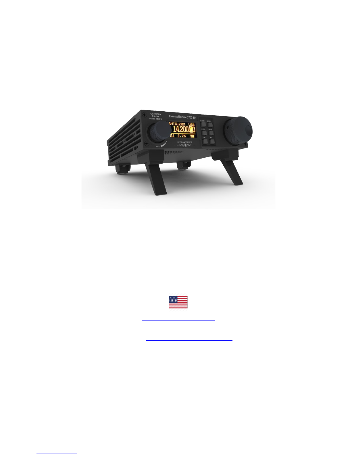
1
USER’s MANUAL
and
Knowledge Base
CommRadio
CTX-10 Amateur Radio Transceiver
AeroStream Communications – CommRadio Division
Commradio div. AeroStream Communicatons All Rights Reserved
No portion of this manual bay be reproduced without permission
CommRadio CTX-10 User Manual – Rev E4 - 15 NOV 2018
New Castle, Colorado USA
www.commradio.com
Email: [email protected]
Copyright © 2018
of CommRadio / AeroStream Communications
Page 2

2
Revision Status
REVISION
DATE
COMMENTS
PRELIM
05/05/2018
Pre-Release Copy
A1
05/15/2018
Initial Release
B
06/26/2018
Added FAQs, added more Tech Notes
C
07/27/2018
Multiple Updates per revised Firmware
D
07/28/2018
Added ATU information
E4
11/15/2018
[T] switch deactivation, non-iambic keyer, MEM, zero-beat
TX ON_OFF elimination, AGC OFF
CommRadio CTX-10 User Manual – Rev E4 - 15 NOV 2018
Page 3

3
Contents
CommRadio ........................................................................................................................ 1
CTX-10 Amateur Radio Transceiver ................................................................................... 1
Revision Status....................................................................................................................... 2
IMPORTANT WARNINGS .................................................................................................. 5
Introduction ............................................................................................................................ 7
Firmware, Manual Updates and Social Media ....................................................................... 8
Actions, Abbreviations & Symbols Used in this Manual ...................................................... 9
Quick Start Guides ............................................................................................................... 10
Quick Start Guide - Receiver Setup ................................................................................. 10
Quick Start Guide – CW Transceiver Setup .................................................................... 12
Quick Start Guide – SSB Transceiver Setup ................................................................... 14
Quick Start Guide – discussion of Digital Data Modes, directly connected to PC ......... 16
Display ................................................................................................................................. 19
Control Knob [M] ................................................................................................................ 20
Transmitter ........................................................................................................................... 21
Keyer ................................................................................................................................ 21
PTT AUDIO..................................................................................................................... 22
TUNING MODE ............................................................................................................. 22
Receiver ............................................................................................................................... 23
Filter ................................................................................................................................. 23
AGC Speed ...................................................................................................................... 23
SQUELCH ....................................................................................................................... 24
BRIGHTNESS ................................................................................................................. 24
STEP TIMING ................................................................................................................. 24
TIMEOUT........................................................................................................................ 24
RAPID TUNE .................................................................................................................. 25
Key Pad ................................................................................................................................ 26
Key Pad - BAND ............................................................................................................. 26
Key Pad – MODE (MODE select function) .................................................................... 26
Key Pad – MODE (Morse Code reader function) ........................................................... 26
Key Pad - STEP ............................................................................................................... 26
Key Pad - MEM ............................................................................................................... 27
Key Pad - <LEFT ARROW> ........................................................................................... 27
CommRadio CTX-10 User Manual – Rev E4 - 15 NOV 2018
Page 4

4
Key Pad - <RIGHT ARROW> (Tuning resolution function) ......................................... 28
Key Pad - <RIGHT ARROW> (Tuning Knob lock function)......................................... 28
Tuning Knob [T] .................................................................................................................. 28
Rear Panel ............................................................................................................................ 29
Power Input ...................................................................................................................... 29
USB .................................................................................................................................. 29
Headphone ....................................................................................................................... 29
SPKR................................................................................................................................ 29
KEY ................................................................................................................................. 30
ACC ................................................................................................................................. 30
MIC .................................................................................................................................. 31
HF .................................................................................................................................... 31
Ground ............................................................................................................................. 31
CTX-10 Technical Notes ..................................................................................................... 32
CTX-10 Power ................................................................................................................. 32
Battery Protection Circuit ................................................................................................ 32
Internal Li-ION Battery Charger ..................................................................................... 32
Monitoring Voltage Input at power jack and Battery Charging ...................................... 33
The Beauty of a COLD BOOT ........................................................................................ 33
Morse Code Reader.......................................................................................................... 33
Beware of interrupting a …Powering Down… Process .................................................. 33
The LOCK function ......................................................................................................... 33
USB Power Bricks for the CTX-10? ............................................................................... 34
Bar Armor for the CTX-10 .............................................................................................. 35
A Peek inside the CTX-10! .............................................................................................. 36
Ambient Noise Gate (ANG) – SSB Audio Processing .................................................... 37
Antenna Tuning Unit – ATU – Some details! ................................................................. 37
CTX-10 Frequently Asked Questions (FAQ) ...................................................................... 38
Q. What was the purpose of the piece of wire wrapped under the Control Knob? ......... 38
Q. The rear of the radio is marked 10 – 20 VDC for power input, but the User’s Guide
says 5 – 20 VDC. Which is it? ......................................................................................... 38
Q. When I whisper into the microphone nothing is transmitted. Is my radio broken? .... 38
Q. How should I clean and protect the finish of my radio? ............................................. 38
Q. How do I ‘Zero Beat’ an incoming CW signal that I want to answer? ....................... 39
CTX-10 Specifications......................................................................................................... 39
CommRadio CTX-10 User Manual – Rev E4 - 15 NOV 2018
Page 5

5
IMPORTANT WARNINGS
READ THIS MANUAL CAREFULLY to learn all of the features of the CTX-10. Understanding
that you’ll want to use the radio immediately, we’ve included several Quick Start Guides
right up front.
SAVE THIS MANUAL as it contains important safety and operating instructions.
FCC INFORMATION This equipment has been tested and found to comply with the limits
for a Class B digital device, pursuant to part 15 of the FCC Rules. These limits are designed
to provide reasonable protection against harmful interference in a residential installation.
This equipment generates, uses and can radiate radio frequency energy and, if not
installed and used in accordance with the instructions, may cause harmful interference to
radio communications. However, there is no guarantee that interference will not occur in
a particular installation. If this equipment does cause harmful interference to radio or
television reception, which can be determined by turning the equipment off and on, the
user is encouraged to try to correct the interference by one or more of the following
measures:
• Reorient or relocate the receiving antenna.
• Increase the separation between the equipment and receiver.
• Connect the equipment into an outlet on a circuit different from that to which the
receiver is connected.
• Consult the dealer or an experienced radio/TV technician for help.
CAUTION: Changes or modifications not expressly approved by
AeroStream/CommRadio could void the user's authority to operate this transceiver under
FCC regulations.
WARNING RF EXPOSURE! This device emits Radio Frequency (RF) energy. Extreme
caution should be observed when operating this device. If you have any questions
regarding RF exposure and safety standards please refer to the Federal Communications
Commission Office of Engineering and Technology’s report on Evaluating Compliance with
FCC Guidelines for Human Radio Frequency Electromagnetic Fields (OET Bulletin 85).
WARNING HIGH VOLTAGE! NEVER touch an antenna or internal antenna connector
during transmission. This may result in an electrical shock or burn.
WARNING! NEVER operate the transceiver while driving a vehicle. Safe driving requires
your full attention—anything less may result in an accident.
CommRadio CTX-10 User Manual – Rev E4 - 15 NOV 2018
Page 6

6
NEVER apply more than 20 V DC, such as a 24 V battery, to the power input jack on the
transceiver rear panel. This could cause a fire or damage the transceiver.
NEVER let metal, wire or other objects touch any internal part or connectors on the rear
panel of the transceiver. This may result in an electric shock or could cause a fire or
damage the transceiver.
NEVER expose the transceiver to rain, snow or any liquids.
TEMPERATURE RANGE - It is acceptable to charge and use the CTX-10 in the temperature
range of 0° – 45° C (32° - 113°F). It is acceptable to store the CTX-10 in the temperature
range of -20° to 45° C (-4° - 113°F). Be aware that temperatures on a vehicle’s dashboard
can exceed +80°C (+176°F), resulting in permanent damage to the transceiver if left there
for extended periods.
CommRadio CTX-10 User Manual – Rev E4 - 15 NOV 2018
Page 7
7
Introduction
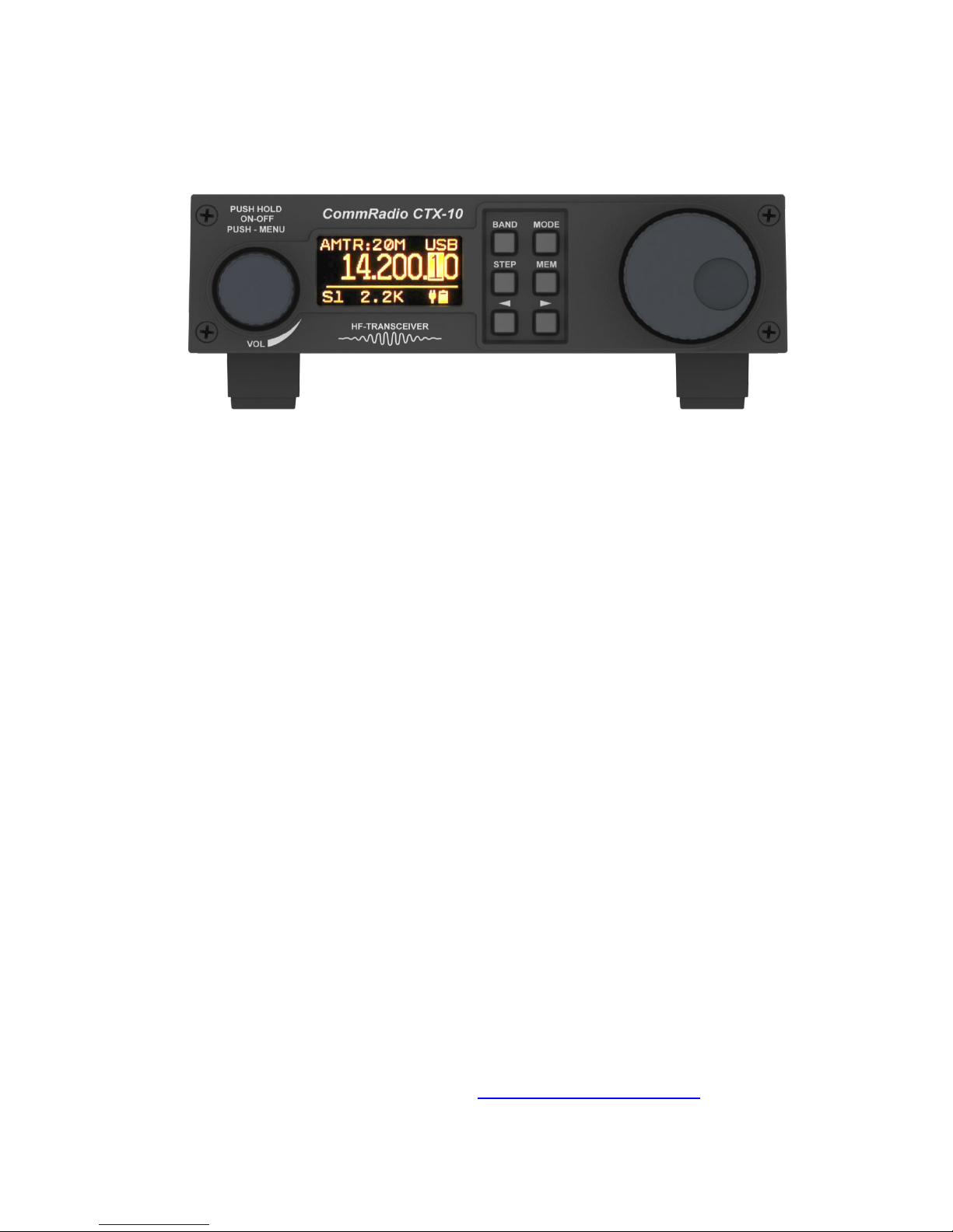
Thank you for purchasing the CTX-10 amateur radio transceiver. Tracing its
evolutionary roots to the commercial/military/avionics worlds, and borrowing
receiver and design elements from the highly successful CommRadio CR-1 and
CR-1a receivers, the CTX-10 is the latest product from the mind of Don Moore,
N0HDX.
The CTX-10 was designed to be rugged and user-friendly with a minimum number
of user interface interactions to produce the desired system functional change.
Standard equipment user replaceable internal Lithium Ion batteries provide power
for a day’s casual operation. The ability to provide operational power and
simultaneously recharge the batteries from most any 5 to 20 VDC source provides
low-cost portable expansion capability and unlimited field operation. Standard
equipment internal wide-range Automatic Antenna Tuner, CW Keyer and CW
Reader provide everything you need for full functionality in one lightweight, diecast aluminum package with no need for supplementary cooling solutions during
high duty cycle operations.
It is the purpose of this manual to provide you with one source for basic through
advanced operations, trouble-shooting, fielding notes and FAQs. This manual will
be maintained as an up-to-date online PDF document, suitable for printing or
viewing on most any electronic device. Be sure to always check the FAQs from
each new revision for the latest and greatest information!
Manual written by Bob Martin, WB2KTG.
Comments and questions regarding the manual or the CTX-10 in general may be
addressed to me at: [email protected]
CommRadio CTX-10 User Manual – Rev E4 - 15 NOV 2018
Page 8

8
Firmware, Manual Updates and Social Media
Contact [email protected] or register online at www.commradio.com to
register your warranty and to automatically receive automated email notices when
updates to firmware or this manual are available. The most recent version of this
manual, system firmware, additional support information and related topics of
interest can always be found on our website: www.commradio.com
The direct dropbox link for the latest user’s manual and system firmware and
firmware update instructions is:
https://www.dropbox.com/sh/o52isgpavqz2org/AACRWiWTE5wNPN9pwO_PeMK
Ya?dl=0
If you’re a friend of social media, CommRadio is on Facebook and Yahoo! Groups,
as well as RadioReference.com.
CommRadio CTX-10 User Manual – Rev E4 - 15 NOV 2018
Page 9

9
Actions, Abbreviations & Symbols Used in this Manual
[AGC] Automatic Gain Control – automatically adjusts RF gain
[ANG] Ambient Noise Gate – automatic SSB audio processing
[ATU] Antenna Tuning Unit – matches CTX-10 to antenna
[BAND] The [BAND] key on the keypad
Click Rotate the Control Knob [M] one detent {CW} or {CCW}
CW Continuous Wave, as in Morse Code
{CW} Clockwise rotation of a knob
{CCW} Counter Clockwise rotation of a knob
<LEFT ARROW> The lower left button on the key pad
LOCK A function of the <RIGHT ARROW> button to LOCK controls
[M] Control Knob, or Menu Knob, the left knob on the front
panel
[MEM] The [MEM] key on the keypad
[MODE] The [MODE] key on the keypad
PUSH Quickly push in and release (holding for less than ½ second)
<RIGHT ARROW> The lower right button on the key pad
[RX] Receive, Receiver
[STEP] The [STEP] key on the keypad
[T] Tuning Knob, the right knob on the front panel
[TX] Transmit, Transmitter
UNLOCK Opposite of LOCK Returns radio to normal operations
CommRadio CTX-10 User Manual – Rev E4 - 15 NOV 2018
Page 10
10
Quick Start Guides
Quick Start Guide - Receiver Setup
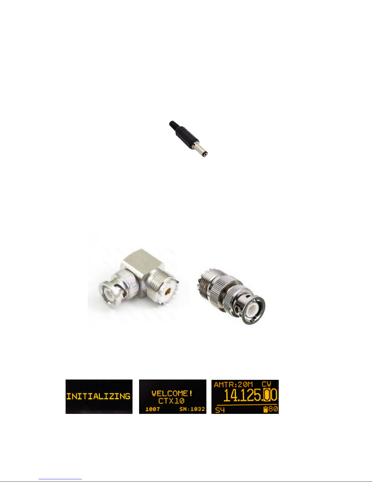
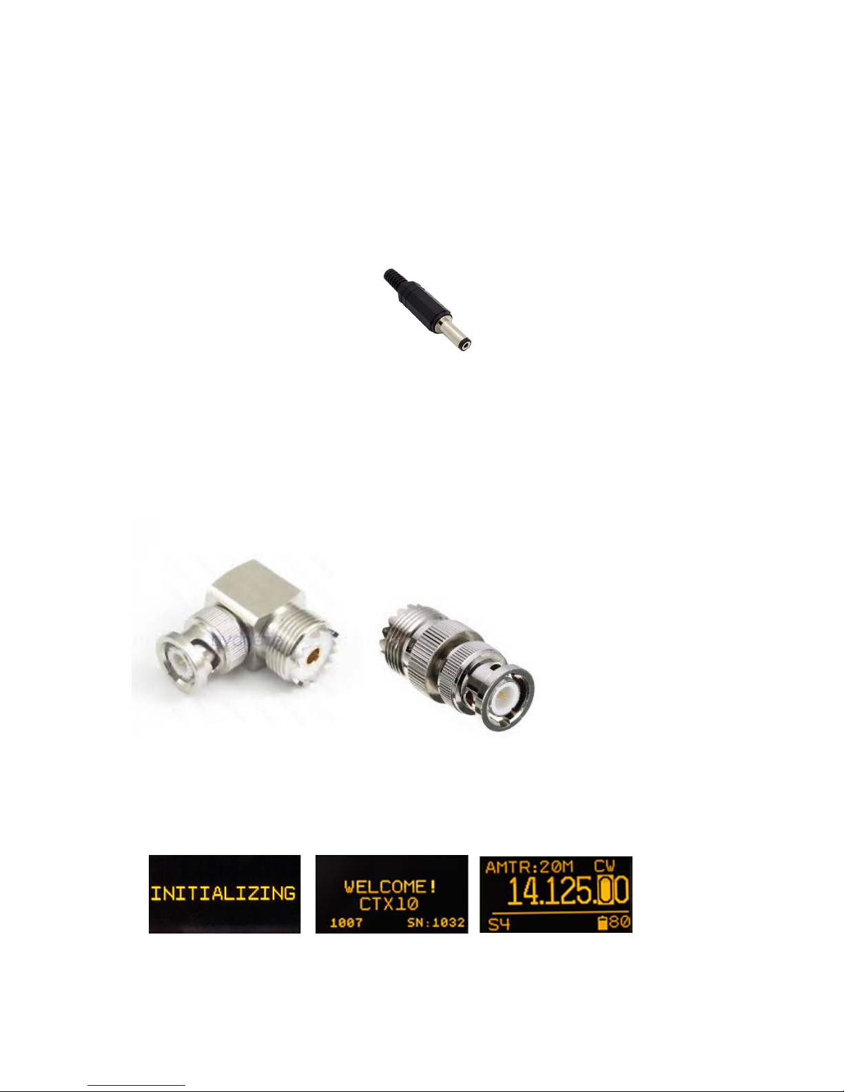
Connect a suitable 5 – 20 VDC power source to the Power Input jack on the rear panel
using a standard 5mm barrel, 2.5mm pin plug. An external power source is not necessary
if the internal batteries have sufficient charge. See below for determining battery charge
status.
Connect an antenna cable to the BNC HF jack on the rear panel. The use of a suitable SO239 Female to BNC Male adapter may be required to connect from an existing antenna
cable to the CTX-10’s BNC connector. These adapters are available in right angle as well as
straight configurations as illustrated below.
Press Control Knob [M] in for two seconds and release. You will see INITIALIZING, the
WELCOME! Screen, then the standard frequency display screen.
CommRadio CTX-10 User Manual – Rev E4 - 15 NOV 2018
Page 11
11
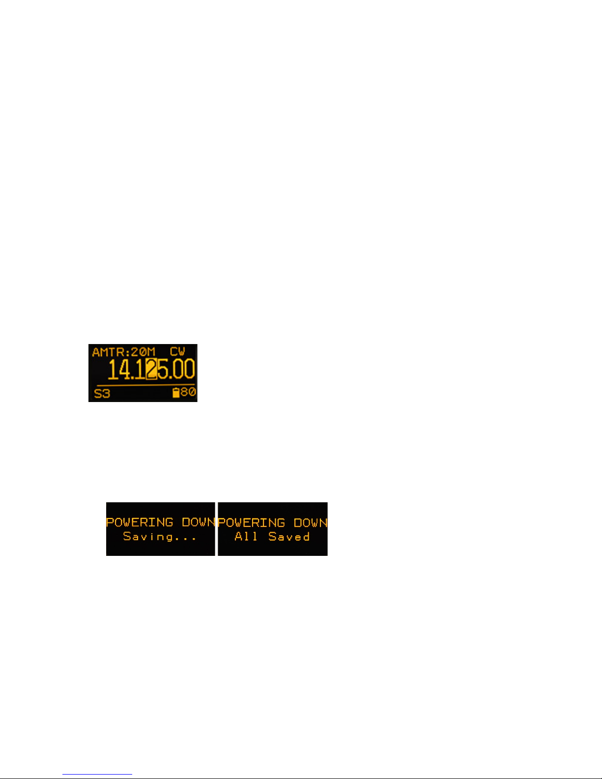
Looking at the display, you see a small battery shaped icon and a number in the lower
right corner. The battery will appear all filled-in when it is holding 100% charge. The
amount of fill-in is a quick indication of the amount of charge. In addition, two digits are
shown to the right of the battery. Those digits give an approximate indication of the
charge status, where 90 represents 90%, 80 represents 80%, etc. NOTE: Battery 100%
charge just shows icon, no numbers. NOTE: When battery charge is less than 20%, battery
icon shows an “X”.
Turn Control Knob [M] {CW} until a suitable audio volume level is heard. Select
desired mode by pressing keypad button MODE repeatedly. Select the desired
amateur band by pressing the keypad button BAND repeatedly. For non-amateur band
reception, select the nearest amateur band and tune up or down selecting an appropriate
tuning step size.
The selected tuning step size is shown by the highlighted digit on the display. To change
the selected tuning step size press the <LEFT ARROW> or <RIGHT ARROW> to move the
selected digit Left or Right. Tuning step sizes of 1MHz, 100, 10, 1 kHz, 100, 10 Hz may be
selected.
Turn Tuning Knob [T] to select the desired frequency.
Enjoy!
To turn OFF, Press Control Knob [M] in for two seconds and release.
If, for some reason the radio does not turn OFF, press and hold Control Knob [M] for six
seconds and the radio will turn off.
CommRadio CTX-10 User Manual – Rev E4 - 15 NOV 2018
Page 12
12
Quick Start Guide – CW Transceiver Setup
Connect a suitable 5 – 20 VDC power source to the Power Input jack on the rear panel
using a standard 5mm barrel, 2.5mm pin plug. An external power source is not necessary
if the internal batteries have sufficient charge. See below for determining battery charge
status.
Connect an antenna cable to the BNC HF jack on the rear panel. The use of a suitable SO239 Female to BNC Male adapter may be required to connect from an existing antenna
cable to the CTX-10’s BNC connector. These adapters are available in right angle as well as
straight configurations as illustrated below.
Press Control Knob [M] in for two seconds and release. You will see INITIALIZING, the
WELCOME! Screen, then the standard frequency display screen.
CommRadio CTX-10 User Manual – Rev E4 - 15 NOV 2018
Page 13
13
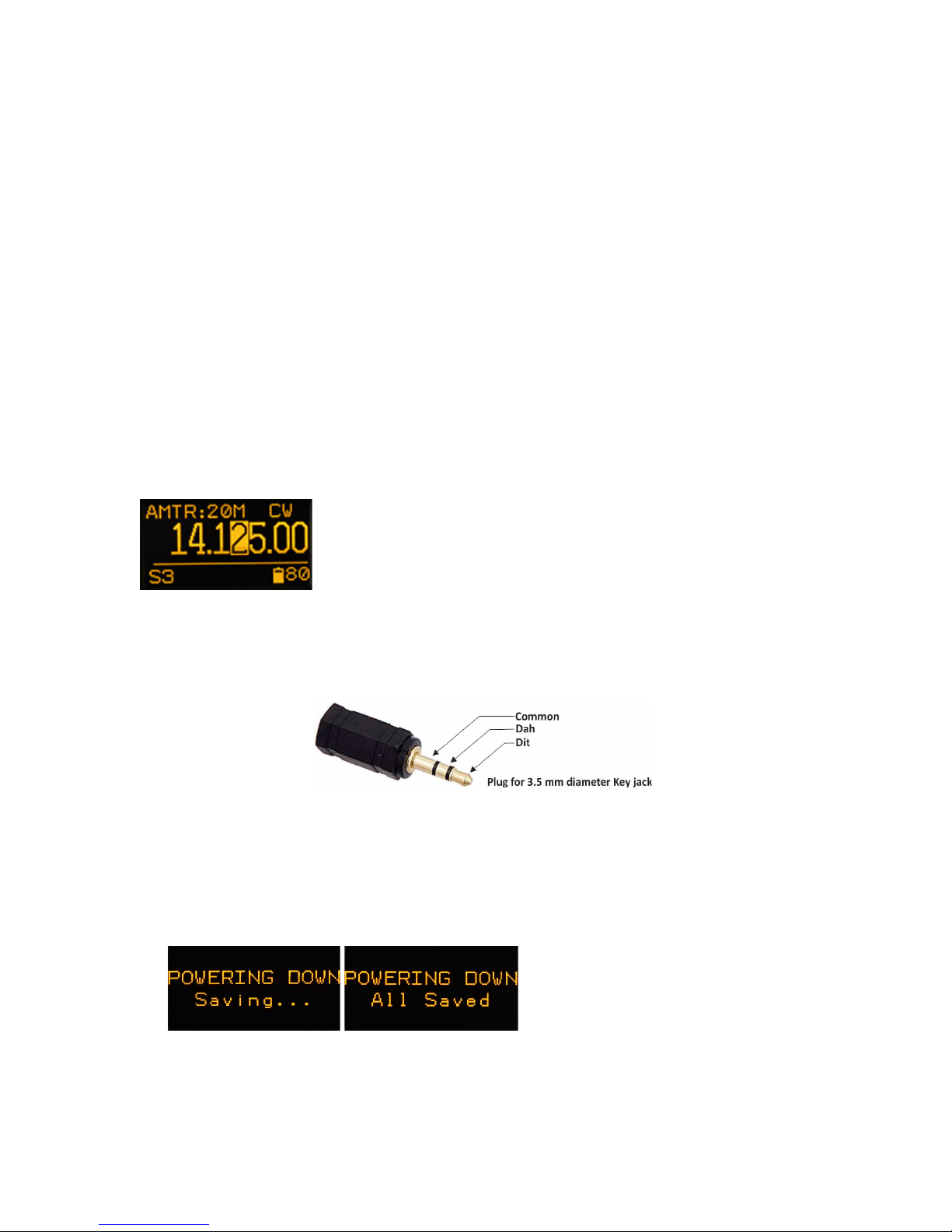
Looking at the display, you see a small battery shaped icon in the lower right corner. The
battery will appear all filled-in when it is holding 100% charge. The amount of fill-in is a
quick indication of the amount of charge. In addition, two digits are shown to the right of
the battery. Those digits give an approximate indication of the charge status, where 90
represents 90%, 80 represents 80%, etc. NOTE: Battery 100% charge just shows icon, no
numbers. NOTE: When battery charge is less than 20%, battery icon shows an “X”.
Turn Control Knob [M] {CW} until a suitable audio volume level is heard. Select desired
mode by pressing keypad button MODE repeatedly. Select the desired amateur band by
pressing the keypad button BAND repeatedly. For non-amateur band reception, select the
nearest amateur band and tune up or down selecting an appropriate tuning step size.
The selected tuning step size is shown by the highlighted digit on the display. To change
the selected tuning step size press the <LEFT ARROW> or <RIGHT ARROW> to move the
selected digit Left or Right. Tuning step sizes of 1MHz, 100, 10, 1 kHz, 100, 10 Hz may be
selected.
Turn Tuning Knob [T] to select the desired frequency.
Connect either straight key or paddles to key jack. For use with an EXTERNAL keyer,
configure CTX-10 as Straight Key – turn the internal keyer OFF.
Push [M] momentarily to enter Menu Selection Mode, then rotate [M] one click {CW} to
enter TX_POWER mode. Push [M] to select current Power. Rotate [M]
{CW} or {CCW} to select 1W, 5W or 10W. Push [M] to select the displayed status.
Enjoy using your CTX-10!
To turn OFF, Press Control Knob [M] in for two seconds and release.
If, for some reason, the radio does not turn OFF, press and hold Control Knob [M] for six
seconds and the radio will turn off.
CommRadio CTX-10 User Manual – Rev E4 - 15 NOV 2018
Page 14
14
Quick Start Guide – SSB Transceiver Setup
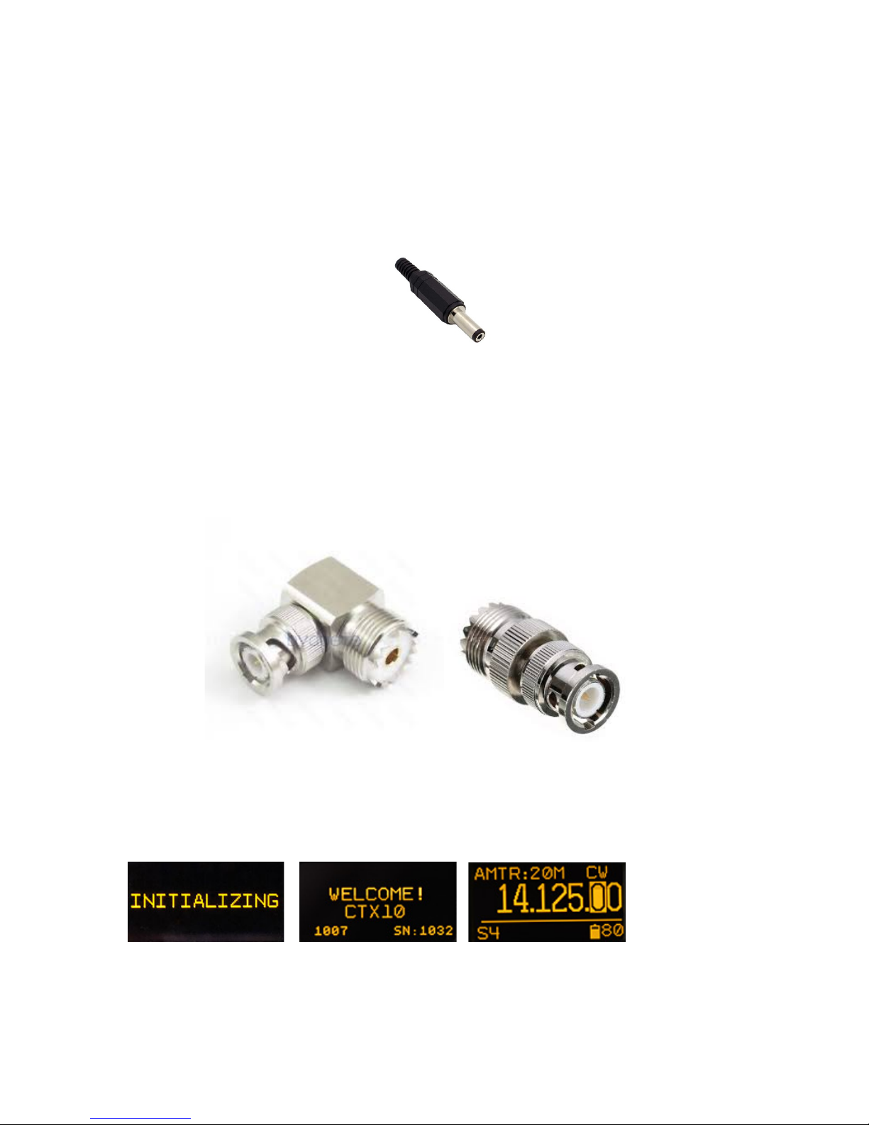
Connect a suitable 5 – 20 VDC power source to the Power Input jack on the rear panel
using a standard 5mm barrel, 2.5mm pin plug. An external power source is not necessary
if the internal batteries have sufficient charge. See below for determining battery charge
status.
Connect an antenna cable to the BNC HF jack on the rear panel. The use of a suitable SO239 Female to BNC Male adapter may be required to connect from an existing antenna
cable to the CTX-10’s BNC connector. These adapters are available in right angle as well as
straight configurations as illustrated below.
Press Control Knob [M] in for two seconds and release. You will see INITIALIZING, the
WELCOME! Screen, then the standard frequency display screen.
Connect compatible microphone to RJ-45 style MIC jack on rear panel. One suggested
microphone is the Yaesu MH-31 A8J.
CommRadio CTX-10 User Manual – Rev E4 - 15 NOV 2018
Page 15
15
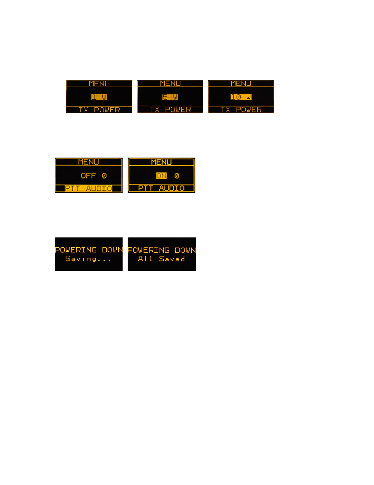
Push [M] momentarily to enter Menu Selection Mode, then rotate [M] one click {CW} to
enter TX_POWER mode. Push [M] to select current Power. Rotate [M]
{CW} or {CCW} to select 1W, 5W or 10W. Push [M] to select the displayed status.
Push [M] momentarily to enter Menu Selection Mode, then rotate [M] three clicks {CW} to
enter PTT AUDIO mode. If required, rotate [M] to cycle to ON. Push [M] to select current PTT AUDIO
mode. PTT ON enables pin 1 of ACC jack, and allows setting of audio level.
Enjoy using your CTX-10!
To turn OFF, Press Control Knob [M] in for two seconds and release.
If, for some reason, the radio does not turn OFF, press and hold Control Knob [M] for six
seconds and the radio will turn off.
CommRadio CTX-10 User Manual – Rev E4 - 15 NOV 2018
Page 16

16
Quick Start Guide – discussion of Digital Data Modes, directly connected to PC
The CTX-10 has been tested using the most popular WSJT-X FT8 data mode. As of June
2018, the starting point for WSJT (Weak Signal Joe Taylor) information is:
https://physics.princeton.edu/pulsar/k1jt/
Refer to the WSJT-X User Guide (all modes) and the FT8 Operating Guide. Mode FT8 was
launched in mid-2017 and rapidly became the most popular mode on HF. It uses
sequential 15 second windows to alternately receive and transmit, requiring accurately
synchronized clocks amongst all stations. This is most easily accomplished by configuring
your PC to automatically update system time using an Internet based time standard.
WSJT-X is user friendly and the interface to the CTX-10 is straight forward, requiring no
third party interfacing hardware.
This mode has a 50% duty-cycle, transmitting 50% of the time, receiving 50% of the time.
Since the CTX-10 is designed to be capable of 100% duty cycle, 50% is very easy duty with
no internal or external fan required. The die cast aluminum CTX-10 enclosure is the
heatsink for all power circuitry, providing excellent convection cooling to the ambient air.
Program Installation: WSJT-X is freeware and is installed on a PC. Use your browser to
search “WSJT-X Download” to locate.
Connections: The only connections are conventional sound card audio (headset and Mic
jacks) lines. No interface electronic box of any kind is required, (e.g. no Signalink USB ™)
1. Connect sound-out (received audio data from CTX-10) from either the headset jack
or pin 5 of the Accessory jack (suggestion: use a commonly available Male-Male 6pin mini-DIN cable, cut in half to give you two interconnect cables).
2. Connect sound-in (from PC-transmitted data) to pin 1 of the Accessory jack.
3. PTT is available on pin 3 of the Accessory Jack if your PC has a serial port.
However, this is unnecessary! The CTX-10 includes an ‘Audio – VOX’ that is
activated and set by the user. Data modes use continuous audio during the entire
transmission and the CTX-10 will turn-on the transmitter when audio is switched
on the WSJT-X GUI.
4. See this User’s Guide, section Rear Panel – ACC for the pin-out of the 6-pin miniDIN connector.
5. Many new laptops do not have the legacy 3.5 mm stereo headset and microphone
jacks. However, some third party laptop docking hubs (for USB 3.0, audio,
monitors, Ethernet) do provide these. An example is the Wavlink Universal USB
CommRadio CTX-10 User Manual – Rev E4 - 15 NOV 2018
Page 17
17
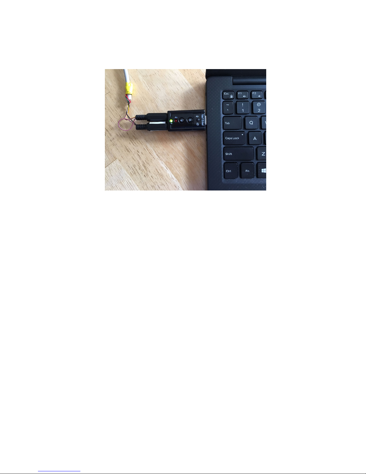
3.0 Docking Station that includes these legacy jacks. Another option is to use a
readily available USB audio dongle, example shown below.
Audio Levels: (One time settings):
1. Audio-out to sound card (received data): Use the audio level control on the left
side of the WSJT-X GUI and set into the ‘green’ on the level bar.
2. Audio-in from sound card (transmitted data). CTX-10 [MODE] must be set to
either USB or LSB (not AM or CW) for the audio level to show on the PTT_AUDIO
screen. The audio level will need careful adjustment. The audio level must be high
enough for full power. However, if set too high, the transmitter will overmodulate and cause interference. The WSJT-X GUI has a level setting bar on the
right side. Note: The CTX-10 will not transmit when on the PTT_AUDIO screen
while using the WSJT ‘TUNE’ button.
a. Start with setting your sound-card audio level at approx. 35 % to 40 %.
b. On the CTX-10, select the ‘PTT AUDIO’ Menu. Select ON (to enable). NOTE:
when on this screen the screen will not ‘time-out’ and will not allow
transmitting, thus enabling the user to use the TEST button on WSJT-FT8 to
adjust the level without transmitting. To exit – push twice or rotate [T]
Tuning Knob one click.
c. Start the audio source (WSJT-X test signal) and advance the WSJT-X Power
level until the CTX-10 screen reads 100 to 130. (That corresponds is 100 to
135 mVrms audio level).
d. Preferred method is to use a dummy load to do this testing to avoid on-
the-air interference. If you must test on-the-air, tune to an open (non datamode) CW frequency and properly identify yourself. The established datamode frequencies are very busy especially during band openings. Your
CommRadio CTX-10 User Manual – Rev E4 - 15 NOV 2018
Page 18

18
fellow operators will appreciate your consideration and courtesy. As a
reminder, The CTX-10 will not transmit when on the PTT_AUDIO screen
while using the WSJT ‘TUNE’ button.
Frequency Control: WSJT-X can control the frequency of many brands of transceivers.
However, at this time, this feature is not supported on the CTX-10. Simply tune your CTX10 to the typical frequencies shown on the WSJT GUI. These frequencies may be stored
in the CTX-10’s memory for easy re-use. Please refer to Key Pad - MEM in this User’s
Manual for details. CommRadio will provide frequency-band changes over USB in the
future (your hardware is compatible). Note: Native USB data mode will not be supported
by the CTX-10, only data via standard soundcard interface.
Operating: The CTX-10 is now a slave to the WSJT-X GUI (except for frequency changes).
Follow the WSJT-X user guides. You can operate (using GUI displayed on PC) with a series
of mouse clicks to answer establish contact by calling or answering a CQ, provide location
and an automatic signal report, send 73, and then auto-log your contact.
CommRadio CTX-10 User Manual – Rev E4 - 15 NOV 2018
Page 19
19
Display
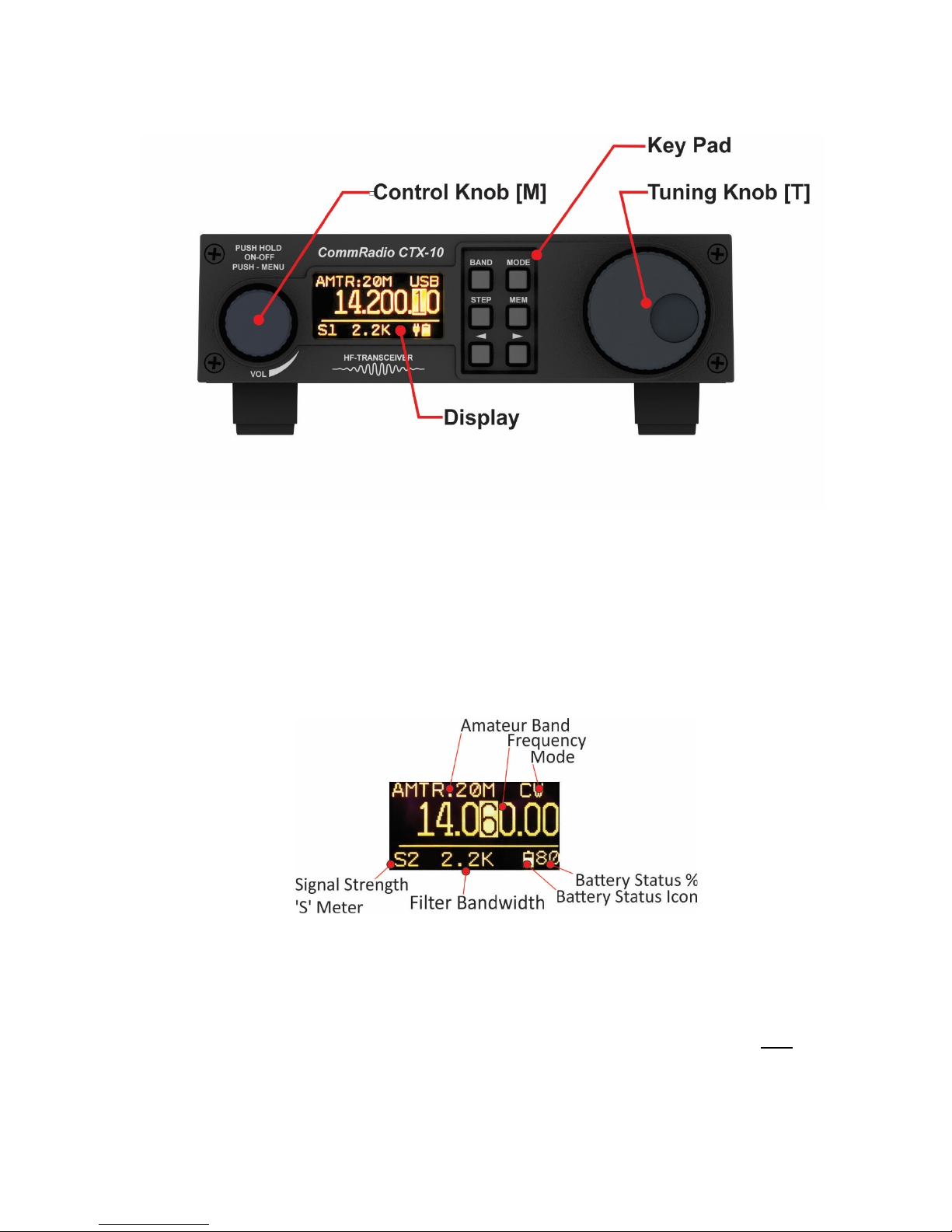
The display is a low power, 64 x 128 pixel, 1.5” diagonal amber Organic Light Emitting
Diode (OLED) component. The glass screen is Electromagnetic Interference (EMI) shielded.
This adjustable intensity display was selected for it’s extremely lower power consumption
and easy viewing indoors in dark environments as well as outdoors under varying ambient
lighting conditions. It is not intended for viewing under direct sun. The display uses very
little power regardless of intensity setting. Set to your personal comfortable intensity.
Above is an example of the display during normal receive conditions. The band selected is
the Amateur 20 Meter band. The mode is CW. The signal strength on the digital ‘S’ meter
is S2. The battery status is 80% charged. The audio filter bandwidth is 2.2 kHz. The display
you see will probably be different based on your selection of operational parameters but
the locations of the data will remain the same. Note: 100% Battery Status shows only a
solid battery icon. No numeric display will show for 100% charged battery.
CommRadio CTX-10 User Manual – Rev E4 - 15 NOV 2018
Page 20
20
Control Knob [M]
Description: Rotary Encoder, 12 detents per revolution with push-in switch. Selection will
automatically time-out for all selections except PTT Audio.
ON/OFF Control
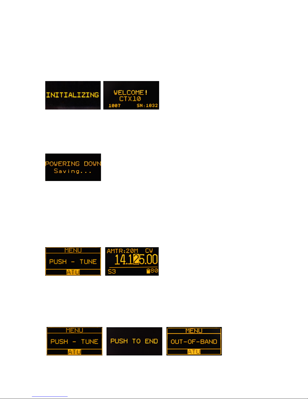
Push and Hold [M] two seconds to turn - ON
The two numbers at the bottom of the WELCOME! screen display are the software revision (left) and
the radio’s electronic serial number. The software revision will change if the software in the radio is
revised. The electronic serial number is permanent for each radio, and is also shown on a label on the
CTX-10’s bottom cover.
Push and Hold [M] two seconds to turn - OFF
Volume Control
Simple rotation of the Control Knob [M] raises or lowers the headset and speaker volume.
NOTE: Separate audio levels are maintained for speaker and headphone jack.
There is no indication of the volume level on the display.
Menu
With power on, Push [M] momentarily to enter Menu Selection Mode. If you wait too long without
action, the display will revert to Display Frequency mode.
The default, first Menu entry visible is the Antenna Tuning Unit (ATU).
Push [M] to TUNE. The ATU screen displays PUSH TO END until the ATU has finished tuning for the
attached antenna, or until [M] is pushed again, ENDing the tuning process. When OUT-OF-BAND is
displayed, the selected frequency is outside the legal US amateur bands. Transmit and Tune functions
are not allowed outside the legal US amateur bands.
CommRadio CTX-10 User Manual – Rev E4 - 15 NOV 2018
Page 21
21
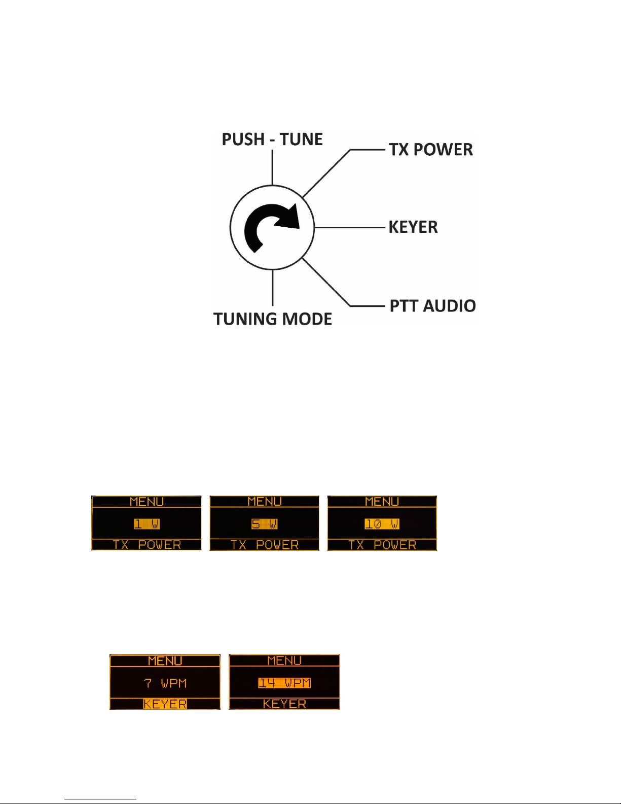
Other Menu selections are grouped by the selected rotation of [M].
{CW} rotation of [M] shows Transmit Menus
{CCW} rotation of [M] shows Receive Menus
{CW} rotation of [M] showing Transmit Menus
Transmitter
Push [M] momentarily to enter Menu Selection Mode, THEN:
TX POWER
Rotate [M] ONE click {CW} to enter TX POWER mode. Push [M] to select current TX POWER level.
Rotate [M] {CW} or {CCW} to cycle through the TX POWER levels: 1W, 5W, 10W. Stop rotating the
knob when the desired power level is selected. Push [M] to select displayed TX POWER level.
Keyer
The CTX-10 Keyer is non-Iambic. It is not possible to software switch right / left paddle inputs to
switch between dits and dahs. Changing right / left function requires changing the wiring to the
paddle. Rotate [M] two clicks {CW} to enter KEYER mode. Push [M] to select current KEYER speed, or
OFF. Rotate [M] to cycle through the options – OFF, 5 WPM through 50 WPM in one WPM
increments. Select OFF if you will be using a straight key.
CommRadio CTX-10 User Manual – Rev E4 - 15 NOV 2018
Page 22
22
PTT AUDIO
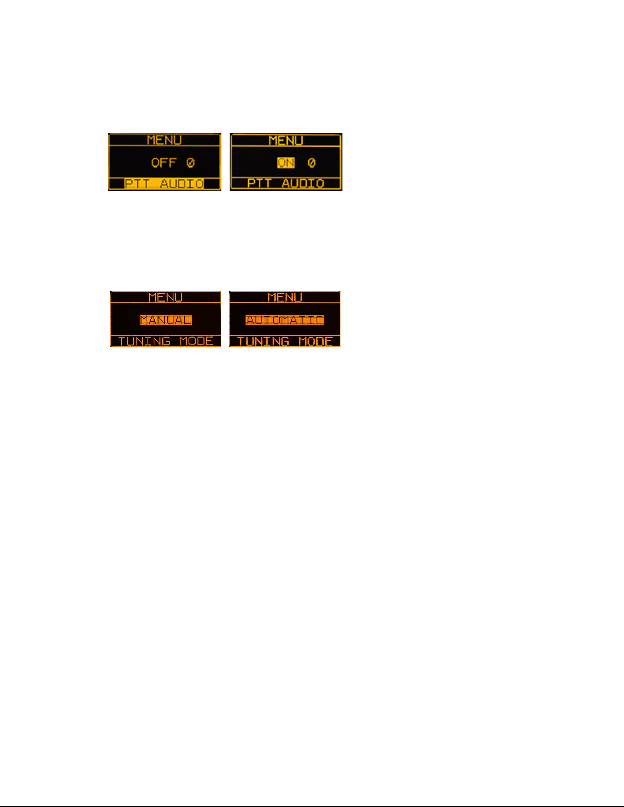
Rotate [M] three clicks {CW} to enter PTT AUDIO mode. Push [M] to select current PTT AUDIO mode.
Rotate [M] to cycle through ON OFF. PTT ON enables pin 1 of ACC jack, and allows setting of audio
level. The digit(s) to the right of ON or OFF indicate the mV level of audio input to the radio.
TUNING MODE
TUNING MODE – Automatic causes the receiver and transmitter to automatically select MODE in
accordance with the current displayed frequency.
TUNING MODE – Manual prevents the receiver from automatically switching MODE.
Rotate [M] four clicks {CW} to enter TUNING MODE mode. Push [M] to select current TUNING MODE.
Rotate [M] to cycle through AUTOMATIC or MANUAL.
CommRadio CTX-10 User Manual – Rev E4 - 15 NOV 2018
Page 23
23
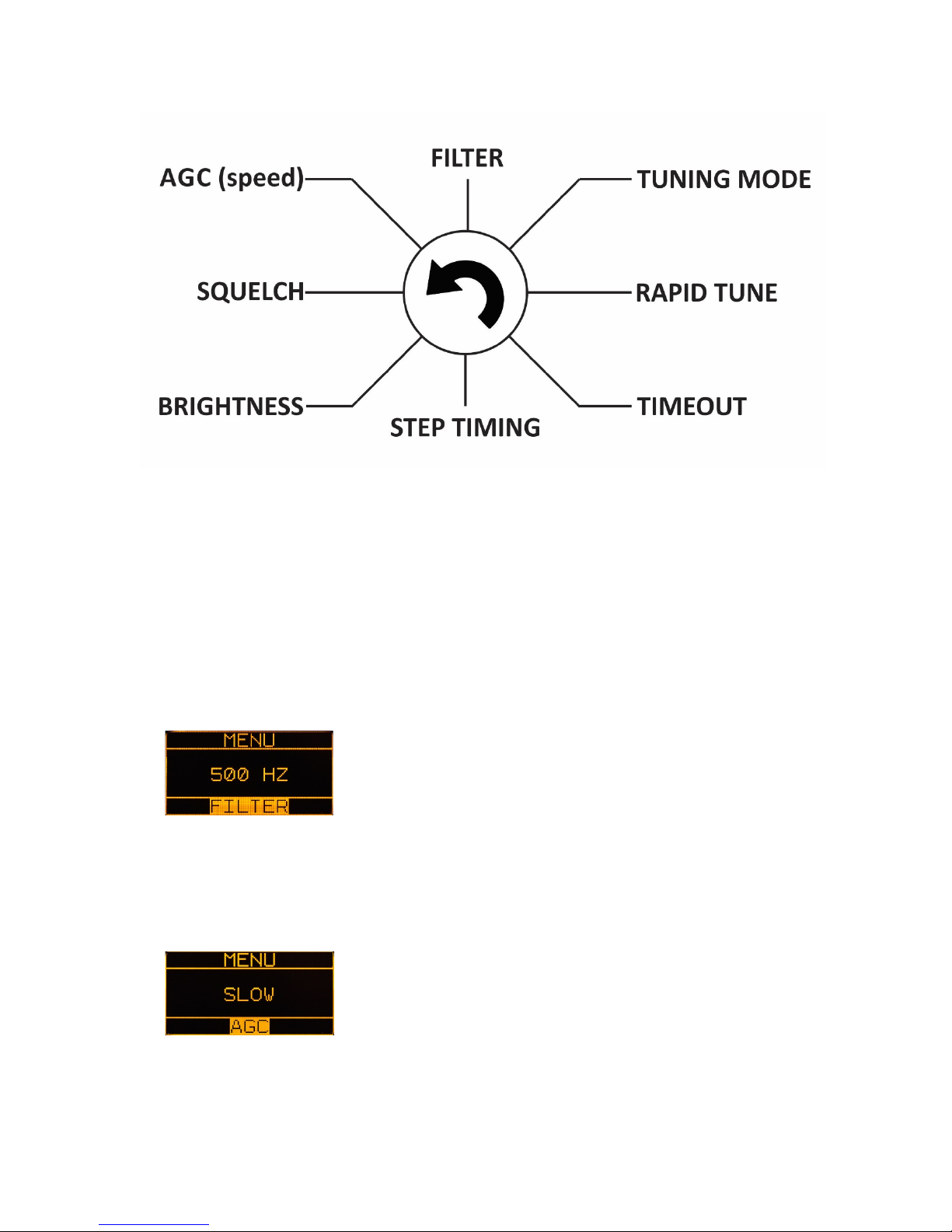
{CCW} rotation of [M] showing Receive Menus
Receiver
Push [M] momentarily to enter Menu Selection Mode, THEN:
Filter
Rotate [M] one click {CCW} to enter FILTER mode. Push [M] to select current receive FILTER
bandwidth. Rotate [M] one click {CW} or {CCW} to cycle through bandwidths available based on the
receiver mode selected (AM, CW, USB, LSB). Push [M] to select the currently displayed level.
AM 5/7.5/15 kHz SSB (USB/LSB)1.8/2.2/2.6 kHz CW 0.5/1/1.8/2.2/2.6 kHz
AGC Speed
Rotate [M] two clicks {CCW} to enter AGC Speed mode. Push [M] to select current receive AGC
Speed. Rotate [M] one click {CW} or {CCW} to cycle through AGC Speeds available. Push [M] to select
the currently displayed level. AGC OFF can be useful for weak signal work, however be aware that the
receiver may overload with inputs greater than -70 dBm. AGC Speeds: OFF SLOW MEDIUM FAST
CommRadio CTX-10 User Manual – Rev E4 - 15 NOV 2018
Page 24
24
SQUELCH
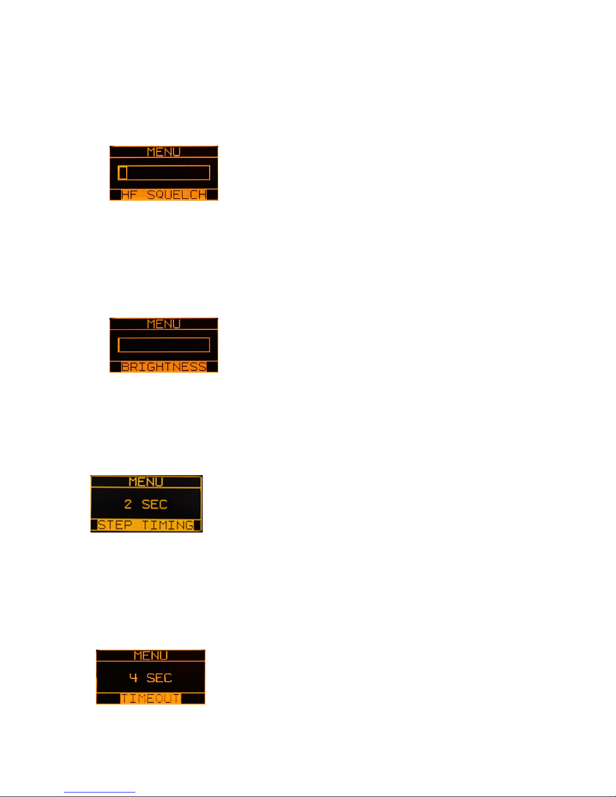
Rotate [M] three clicks {CCW} to enter SQUELCH mode. Push [M] to select current SQUELCH level.
Rotate [M] {CW} or {CCW} to change the SQUELCH level based on the lighted bar on the screen. Push
[M] to select the currently displayed level. NOTE: Setting the SQUELCH control too high may make the
radio appear to be ‘deaf’ with normal signal levels.
BRIGHTNESS
Rotate [M] four clicks {CCW} to enter BRIGHTNESS mode. Push [M] to select current
BRIGHTNESS level. Rotate [M] {CW} or {CCW} to change the BRIGHTNESS level based on
the lighted bar on the screen. Push [M] to select the currently displayed level. The display
uses very little power regardless of intensity setting. Set to your personal comfortable
intensity.
STEP TIMING
STEP TIMING is the dwell time at each frequency step during stepping or MEM stepping.
Rotate [M] five clicks {CCW} to enter STEP TIMING mode. Push [M] to select current STEP
TIMING selection. Rotate [M] {CW} or {CCW} to change STEP TIMING. Push [M] to select
the currently displayed time.
Selectable STEP times: 10s, 5s, 2s, 1s, 500ms, 250ms
TIMEOUT
TIMEOUT is the period of time a menu selection will stay active prior to returning to the
Frequency Display screen.
Rotate [M] six clicks {CCW} to enter TIMEOUT mode. Push [M] to select current TIMEOUT selection.
Rotate [M] {CW} or {CCW} to change TIMEOUT. Push [M] to select the currently displayed time.
Selectable TIMEOUT times: 5s, 4s, 3s, 2s
CommRadio CTX-10 User Manual – Rev E4 - 15 NOV 2018
Page 25
25
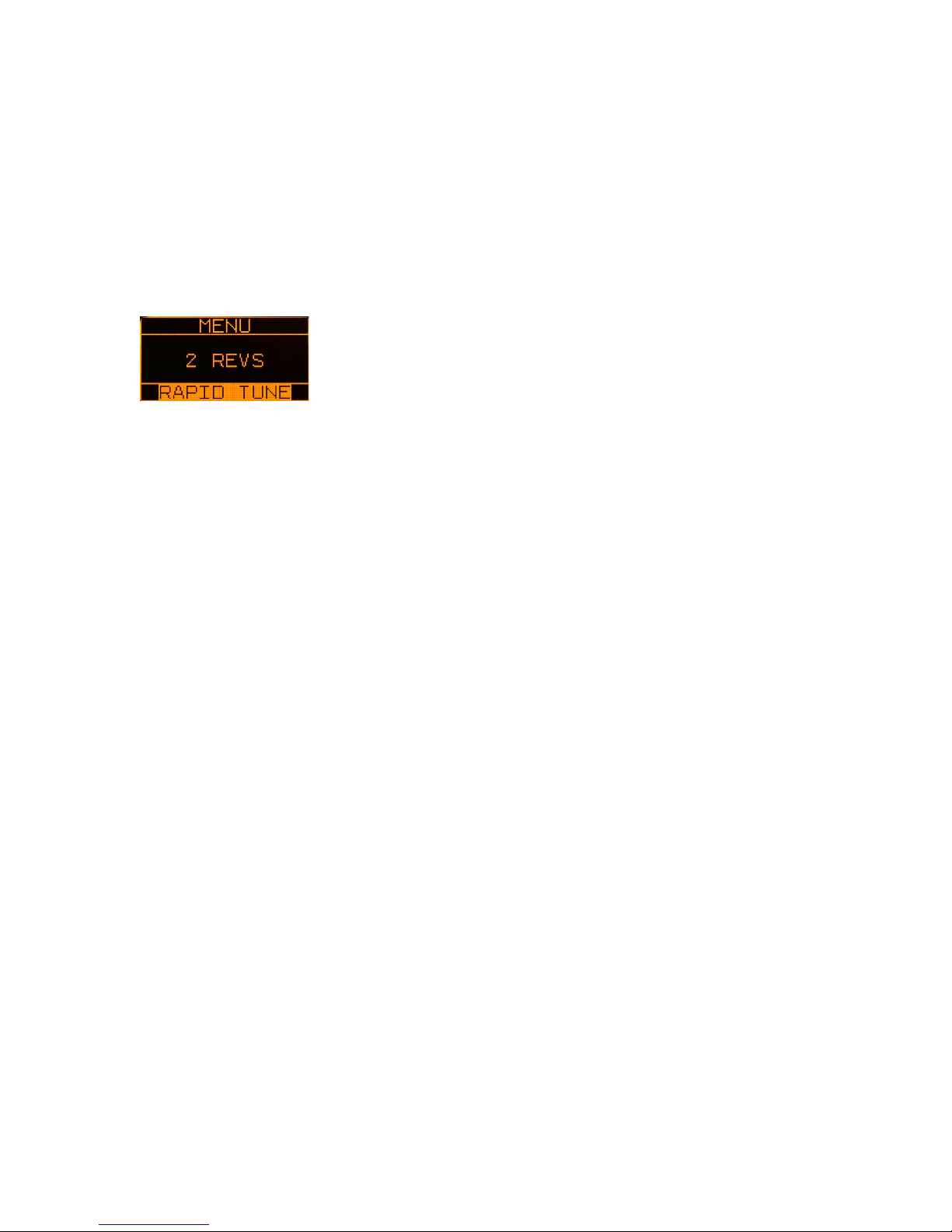
RAPID TUNE
When AUTOMATIC Tuning Mode is selected, RAPID TUNE is the number of high speed
revolutions of the [T] knob before it ‘shifts gears’ from 0.1 kHz to 1.0 kHz and
automatically increases the tuning rate. RAPID TUNE reverts back to 0.1 kHz speed when
the knob is slowed down or stopped.
Rotate [M] seven clicks {CCW} to enter RAPID TUNE mode. Push [M] to select current RAPID TUNE
selection. Rotate [M] {CW} or {CCW} to change RAPID TUNE. Push [M] to select the currently
displayed RAPID TUNE.
Rapid Tune Options: 10, 8, 6, 4, 2, OFF Revolutions before beginning to RAPID TUNE
CommRadio CTX-10 User Manual – Rev E4 - 15 NOV 2018
Page 26
26
Key Pad
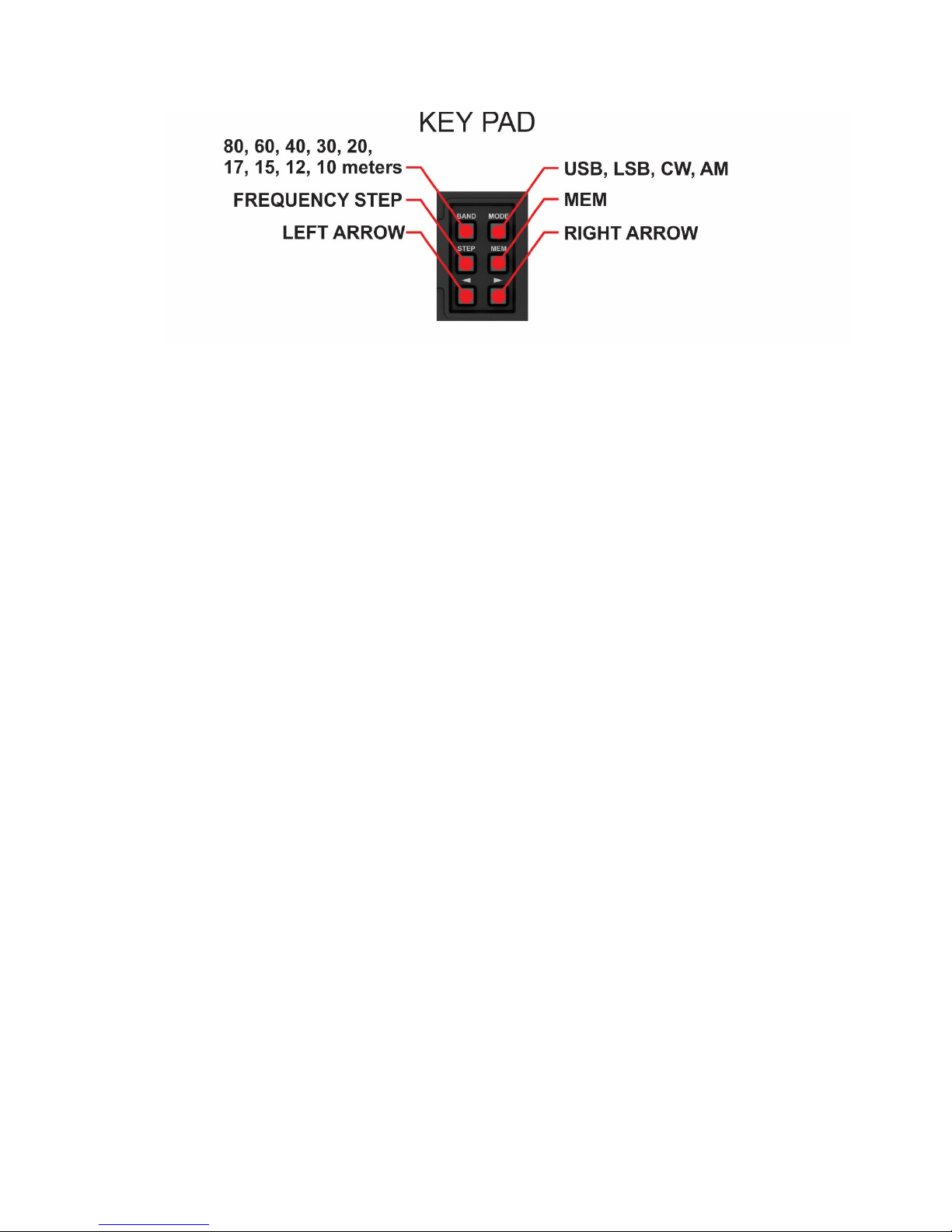
The Key Pad is a set of six position momentary contact push button switches. Each of the buttons’
functions are described below.
Key Pad - BAND
With the current frequency displayed, pressing the BAND button will change the
active frequency to the amateur radio band displayed in the upper left corner of the display.
The options are: AM RADIO/160M/80M/60M/40M/30M/20M/17M/15M/12M/10M
NOTE: 160M and AM RADIO are receive only.
Key Pad – MODE (MODE select function)
With the current frequency displayed, pressing the MODE button will change the
demodulation method used by the DSP. The currently active mode is displayed in the upper right
corner of the display. The options are: AM/CW/LSB/USB
NOTE: AM mode is receive only.
Key Pad – MODE (Morse Code reader function)
With the current frequency displayed, pressing and HOLDing the MODE button will bring up the
Morse Code Reader screen. At the top of the screen will be a small digit active display of the currently
tuned frequency. In the main body of the screen will be the decoded Morse code text. This function
works best on machine sent code with high signal-to-noise ratio. Generally, the more narrow the
audio filter, the better results you will see. Please refer to Technical Notes section for further info.
Key Pad - STEP
With the current frequency displayed, pressing the STEP button causes the receiver to
immediately begin incrementing the displayed frequency (frequency STEPPING). The size of the
STEP is determined by the location of the highlighted digit on the displayed frequency immediately
before pressing the STEP button. To terminate the STEP function, either rotate [T], the Tuning
Knob or press the STEP key again. This function is useful for casually listening to an amateur band
to determine how active it is. Appropriate selection of STEP size allows you to select your desired
level of resolution. The upper and lower frequency limits for each amateur band selected for the
STEP function cannot be changed by the user. NOTE: When on a MEM page, STEP will cycle through
saved memories, with [<] and [>] reversing STEP direction. Press STEP again to stop.
CommRadio CTX-10 User Manual – Rev E4 - 15 NOV 2018
Page 27
27
Key Pad - MEM
With the current frequency displayed, pressing the MEM button button brings up the
Memory screen. Memory is divided into eight pages of eight entries for a total of 64 separate
memory locations. With the Memory screen active, use the <LEFT ARROW> and <RIGHT ARROW>
to select the desired page of memory. The currently tuned frequency is displayed in the upper
right corner of the display. When you are on the desired memory page, press MEM again to jump
down to the memory entries. Using the <LEFT ARROW> and <RIGHT ARROW> jump through the eight
memory entries on the page. If you go too far, you will cross the page boundary and jump to the next
(or previous) page. To go back to the original page, simply press the other arrow button.
To save the frequency in the upper right corner of the display into a memory location, select the
memory page, select the desired memory entry on the page, press MEM and hold for 2 seconds. The
frequency will be stored in the desired memory location. Repeat until you have populated the
memory page(s) with your selected frequencies.
To recall a frequency to the display, go to the desired memory entry, and press MEM. The selected
frequency will now become the active frequency on the screen.
To STEP through (scan) the memory entries on a page, select the page you want to STEP through by
pressing the MEM button and the <LEFT ARROW> and <RIGHT ARROW> . Press MEM again to select
any memory entry on the page. Press the STEP button to begin stepping through all eight memory
entries on the page. If you have less than eight frequencies on the page, only the NON-EMPTY entries
will be scanned. To stop stepping press the STEP button again. The STEP time (the dwell time at each
frequency) is set using the receiver setting STEP TIMING.
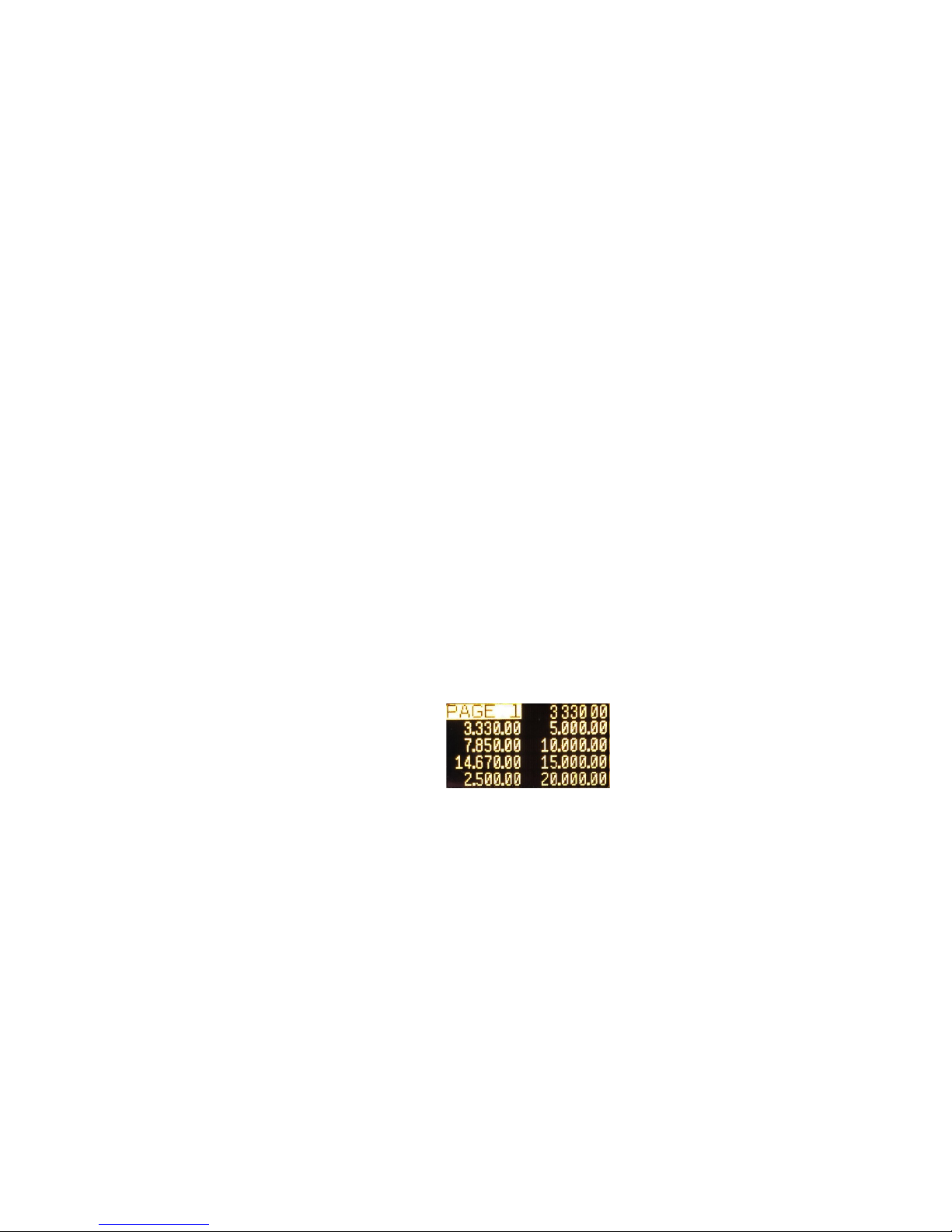
Above is an example of a completely filled out memory page. I’ve added all of the Canadian CHU and
United States’ WWV frequencies. When I want to get a sense of HF propagation, I’ll STEP through
these frequencies continuously, listening for the time signals. The upper right corner shows 3.330.00,
the frequency currently on the general display screen. At this time, there is no capability to erase one
or more entries on a memory page. One alternative is to have duplicate entries of the same desired
frequencies. These memories are safely retained even after re-flashing or upgrading the system
operational firmware.
Key Pad - <LEFT ARROW>
With the current frequency displayed and one digit highlighted with a rectangular lighted box,
pressing the <LEFT ARROW> causes the highlighted box to move one digit to the left.
This highlighted box indicates the digit to be changed when rotating [T] the Tuning Knob.
Tuning Resolutions: 1MHz, 100, 10, 1 kHz, 100, 10 Hz. Additionally, BAND and MODE can be changed
once their function is selected. The direction of STEP may also be changed.
CommRadio CTX-10 User Manual – Rev E4 - 15 NOV 2018
Page 28

28
Key Pad - <RIGHT ARROW> (Tuning resolution function)
With the current frequency displayed and one digit highlighted with a rectangular lighted box,
pressing the <RIGHT ARROW> causes the highlighted box to move one digit to the right.
This highlighted box indicates the digit to be changed when rotating [T] the Tuning Knob.
Tuning Resolutions: 1MHz, 100, 10, 1 kHz, 100, 10 Hz. Additionally, BAND and MODE can be changed
once their function is selected. The direction of STEP may also be changed.
Key Pad - <RIGHT ARROW> (Tuning Knob lock function)
During normal operation of the radio, pressing and holding the <RIGHT ARROW> key for 2
seconds LOCKs control of the [T] Tuning Knob and [M] Main Knob except for [M] still
controlling audio volume. This can be useful, for example, if you want to operate the radio
while stowed in your rucksack, and not have to worry that the frequency may accidentally
change. To UNLOCK the radio, simply press <RIGHT ARROW> for 2 seconds.
Tuning Knob [T]
Is a precision low torque digital optical encoder. Also, [T] incorporates an axial momentary push
button switch. This switch function is not presently used by the CTX-10. Rotation of [T] {CW} increases
the displayed frequency with a step size as indicated by the highlighted display digit. Similarly,
rotation of [T] {CCW} decreases the displayed frequency.
CommRadio CTX-10 User Manual – Rev E4 - 15 NOV 2018
Page 29
29
Rear Panel
Power Input
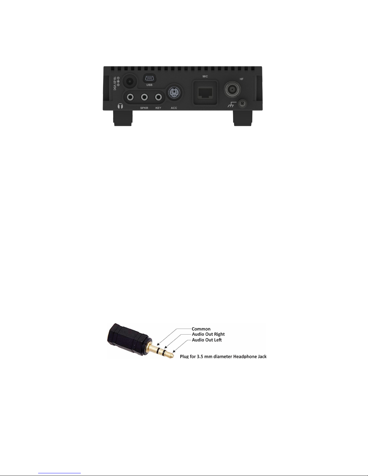
The power input jack is a standard 2.5mm pin x 5mm barrel, pin positive (+) power
receptacle. Recommended input voltage range is 5 – 20 VDC, 20 VDC is the absolute
maximum. A recommended power supply should provide at least 35 W.
USB
The USB receptacle is a standard mini-B 2.0 jack. This USB receptacle is the input jack for
software updates to the CTX-10. Additionally, the jack provides IQ data out from the
receiver, and provides bi-directional radio control capabilities. NOTE: USB receptacle does
not provide power out and does not accept power in.
Headphone
The headphone jack is a standard 2.5mm stereo jack providing volume controlled output
levels adjusted by rotation of Control Knob [M]. A stereo connected jack is provided so
you can hear the same audio on both L and R channels.
NOTE: Use this headphone jack as signal source for external POWERED speakers,
POWERED monitor speakers, or any other active circuitry.
SPKR
The SPKR jack is a standard 2.5mm stereo jack providing volume controlled output levels
adjusted by rotation of Control Knob [M]. Inserting a suitable plug into this jack
automatically disconnects the internal speaker, allowing all output
NOTE: For use of external passive (NON-POWERED) speakers only. To achieve maximum
efficiency and minimal power drain, the internal speaker and this SPKR jack are powered
CommRadio CTX-10 User Manual – Rev E4 - 15 NOV 2018
Page 30
30
by a differential (non-ground referenced) amplifier. Damage can occur if this output is
connected to a ground-referenced device. DO NOT connect to any powered circuitry.
KEY
The KEY jack is a standard 2.5mm stereo jack and is the input port for either a straight key
or a three wire paddle. Using a straight key, the key turns the CW signal on and off. Using
a paddle, the paddle is the input to an electronic keyer which turns the CW signal on and
off. To use an EXTERNAL electronic keyer, configure the KEY input to straight key.
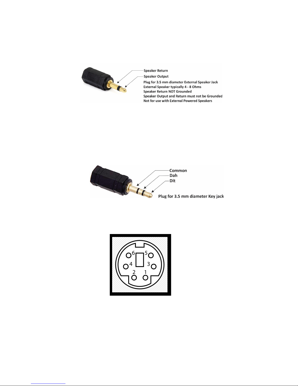
ACC
The ACC or accessory jack is a standard 6 pin (female) mini-DIN receptacle, sometimes
referred to as a PS/2 connection. Wiring diagram for the ACC receptacle:
Pin 1, AUDIO IN, 100 – 125 mV RMS audio from PC soundcard (TX Data). Used with data-mode
transmissions. This line is monitored to enable transmit mode (no separate PTT required).
Pin 2, GROUND
Pin 3, PTT, Push-To-Talk, Pull-low (Ground) this pin to enable SSB transmission. (Optional, see pin 1)
Pin 4, MUTE, Pull-low (Ground) this pin to mute receiver. (Pins 1 and 3 also mute receiver)
Pin 5, AUDIO-OUT, Line-level audio output to PC soundcard (RX Data)
CommRadio CTX-10 User Manual – Rev E4 - 15 NOV 2018
Page 31
31
Pin 6, KEY-OUT, Used with compatible linear amplifier to operate the amplifier’s T/R relay during TX.
This pin is an open-collector and will ground the linear amplifier’s T/R relay. This line will handle up to
225 mA current and up to 50VDC (13.6 VDC nominal). The internal resistance of the amplifier’s T/R
relay is expected to be high enough to limit the current (greater than 60 Ohms at 13.6 VDC) Check
with your amplifier’s manufacturer for relay resistance and other parameters.
MIC
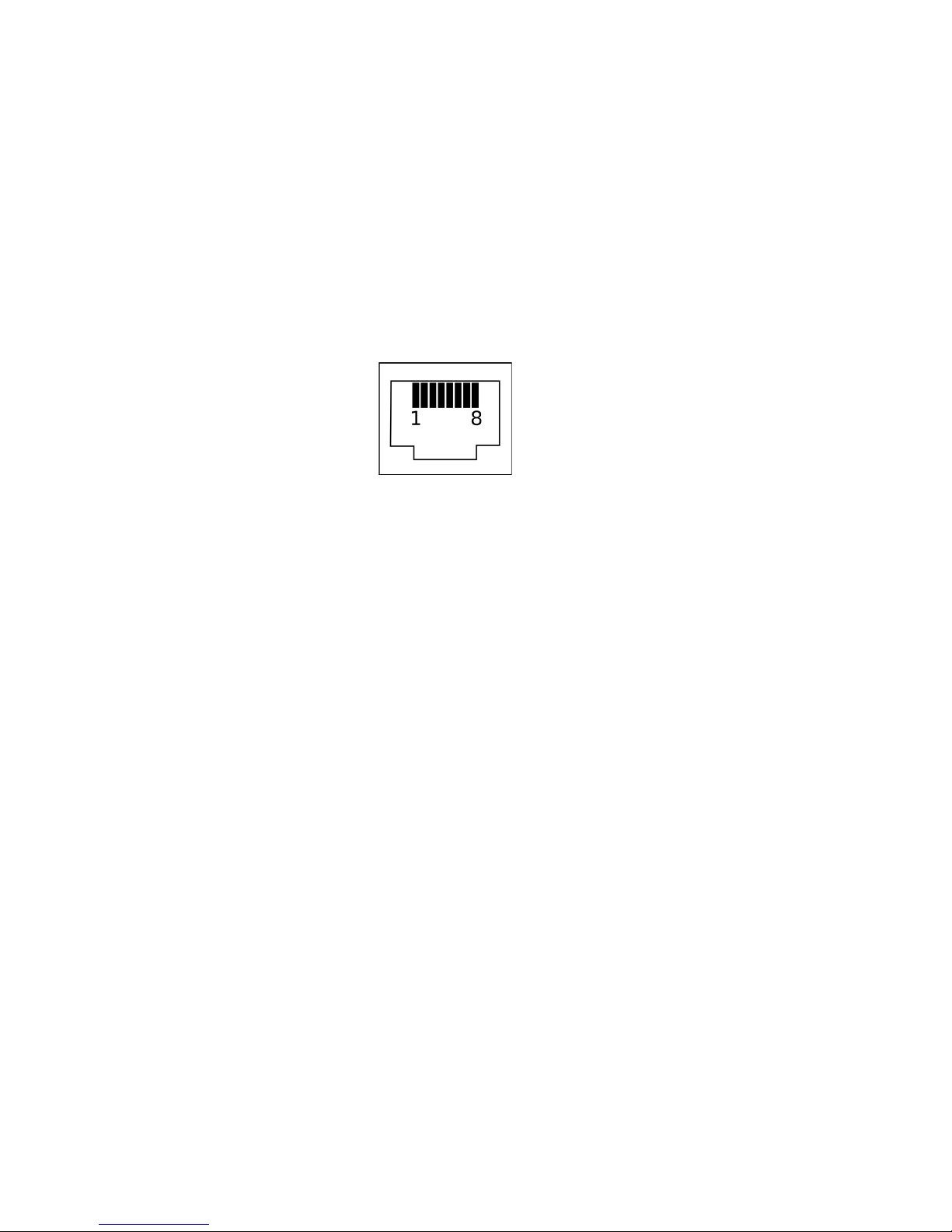
The MIC or microphone jack is the input port for a microphone for SSB communication. The eight
conductor modular (RJ-45 type) receptacle has been tested and found compatible with Yaesu MH-31
A8J and MFJ-290MY push to talk microphones.
Pin 4, MIC Ground
Pin 5, MIC In
Pin 6, PTT, Push-To-Talk, Pull-low (Ground) this pin to enable SSB transmission.
Pin 7, Ground
HF
The HF connector is the RF 50 Ohm impedance input/output connection to the CTX-10
transceiver. It is a female BNC (Bayonet Neill–Concelman) controlled impedance 50 Ohm
connector. For connection to a standard male UHF plug cable termination, a UG-225/U
(SO-239 (UHF) to BNC male adapter) is suggested.
Ground
A Ground (chassis) connection is provided on the CTX-10. The topic of whether or not, and
how to ground your radio is well beyond what can be written in a few sentences or a few
pages. Popular knowledge and personal recommendations on the topic are frequently
wrong. A recommended practical reference on the topic is: ARRL’s Grounding and Bonding
for the Radio Amateur, available directly from the ARRL or most Amateur Radio resellers.
One common use of the Ground connection is to connect to the ground terminal of the
three wire outlet providing power to the CTX-10 power supply. In addition to providing a
Safety Ground, this connection may reduce background noise when listening to the radio.
CommRadio CTX-10 User Manual – Rev E4 - 15 NOV 2018
Page 32

32
Voltage: 3 Cells in Series (VDC)
Percent (%) Remaining
12.2 - 12.6
100 RX-TX
11.9
90 RX-TX
11.7
80 RX-TX
11.4
70 RX-TX
11.1
50 RX-TX
10.95
30 RX-TX
10.8
20 RX-TX
10.5
10 RX Only
<10.5
Shutdown by controller
CTX-10 Technical Notes
CTX-10 Power
Three (3) Tenergy model 30006, type 18650 cylindrical Li-Ion cells, rated at 3.7V @ 2600
mAhr are connected in series. These batteries are easily user replaceable after removing
eight screws securing the CTX-10 case bottom cover. Soldering is not required. Batteries
fit into 3 slot holder.
The total battery-pack capacity is:
7800 mAhr (3 cells x 2600/ea.)
32,760 mWhr (4.2V x 7800). (4.2 V is the cell voltage when 100% charged.)
Battery Protection Circuit
Each individual battery cell has an internal protection circuit to avoid excessive chargingdischarging current and over or under voltage conditions. The internal battery protection
circuits will trip and the radio will drop off-line without warning if the batteries become
fully discharged. This condition is avoided by the CTX-10’s PIC24 microcontroller
monitoring battery voltage. However, if any of the batteries trip, the batteries will reset
when external power is applied. The CTX-10 will then power-up normally.
Internal Li-ION Battery Charger
The batteries are maintained by a combined switch-mode converter with internal chargecontroller that maintains a charge rate of approximately 10 to 12 Watts into the battery
stack regardless of external power-source voltage. Optimal charging performance with
less than 1 Amp current draw requires between 10 – 20 VDC. Charging with as low as 5V is
possible but will require up to 2 Amps current draw. Be aware of the current output
capability of your power source.
The cells are fully charged at 4.2 V (12.6 VDC battery bus) and 90% discharged at 3.5V
(10.5 VDC battery bus). See table below.
CommRadio CTX-10 User Manual – Rev E4 - 15 NOV 2018
Page 33

33
Monitoring Voltage Input at power jack and Battery Charging
The presence of a voltage greater than (>) 0.3 VDC indicates the presence of the power
source (power supply, battery, etc.). Any voltage in the range of 5.0 – 20V will allow
charging. When a power source is present, the batteries will be charged with the CTX-10
either ON or OFF.
The internal micro-processor will prevent transmitting (at any RF power setting), once the
battery charge state has fallen below 20% remaining capacity. Receiver-only operation
can continue down to 10% capacity before an orderly shut-down (with data saved) is
initiated.
The Beauty of a COLD BOOT
As anyone who has ever used a computer will tell you, the longer it runs the more likely it
is that something will get corrupted and the performance will suffer, until you perform a
COLD BOOT. The design of the CTX-10 intentionally removes power from all software
driven processes upon power down. Upon power up all processes are initialized, all
functional parameters reset, and everything performs ‘just like new’. Your last operational
settings, which were stored in flash memory during the graceful power off, are reloaded
from flash storage saving you setup time. Therefore, in the highly unlikely event that the
radio ever locks-up or misbehaves, turning the power OFF and back ON should resolve the
problem. If the radio won’t shut off after a normal OFF push, holding the [M] in for 6
seconds will turn power off.
Morse Code Reader
A handy feature for those of us who are not fluent in Morse is a built-in Morse Code reader. To use
this feature, tune around to some frequency with Morse Code activity. Press and hold the MODE key
and the screen will change to show the active frequency in the upper right portion of the display, and
the decoded Morse Code in the larger portion of the screen. Adjust the tuning knob, and filter
bandwidth for best results. One method that works it to listen around using 1.0 to 2.6kHz audio filter.
When you find a signal of interest switch down to 0.5kHz bandwidth for best copy. No, it isn’t as good
as a finely tuned Mark V Mod 0 brain/ear combo, but then again, nothing is. This function works best
on machine sent code with high signal-to-noise ratio.
Beware of interrupting a …Powering Down… Process
Holding the [M] down will initiate a Powering Down process. If you press and/or hold [M]
while the display shows Powering Down, you may (or may not) stop the process. Stopping
the process mid-way through like this may result in the audio or some other function not
performing properly. If this should happen, simply press and hold [M] again, allowing the
process to gracefully complete. Once again, The Beauty of a COLD BOOT.
The LOCK function
When using the radio, sometimes you just want to stay on one frequency and monitor or
communicate. An easy way to ensure the frequency doesn’t change is to press and hold
the <RIGHT ARROW> on the Key Pad. After holding for about two seconds, a small LOCK
CommRadio CTX-10 User Manual – Rev E4 - 15 NOV 2018
Page 34

34
icon appears on the bottom of the display. When the LOCK is shown, rotation of [T] will
not cause the frequency to change. This may be helpful when you want to operate with
your CTX-10 in your rucksack, or if little fingers may get curious… Pressing and holding
<RIGHT ARROW> again will remove the LOCK icon and restore function of [T].
USB Power Bricks for the CTX-10?
The CTX-10 will accept a power input of as low as 5VDC. I have several USB Power Bricks
from Radio Shack and SOLIO. A couple provide as low as 3.1VDC output. These are not
acceptable, you really need about 5VDC, ideally at 2A. If you are experiencing difficulty
with a particular Power Brick, measure the output voltage to make sure it is at least 5VDC.
Also remember that the mini-USB jack on the rear panel of the CTX-10 is for Data I/O only.
Power must be input to the 2.5mm pin x 5mm barrel, pin positive (+) power receptacle.
Although I haven’t tried it, hooking two, less than 5 VDC power bricks in series would
probably work just fine. NOTE: For best results, if using a good 5V power brick, the
batteries should be pre-charged to at least 60%. During transmit, lower than expected
output power may result. NOTE: An external power source will ALWAYS charge the
battery with power ON or OFF, or if TRANSMITTING or RECEIVING.
CommRadio CTX-10 User Manual – Rev E4 - 15 NOV 2018
Page 35
35
Bar Armor for the CTX-10
The CTX-10 is a ruggedized radio able to withstand shock, vibration and temperatures
which would render lesser radios into a collection of spare parts. However, the CTX-10’s
Achille’s Heel just might be the front panel. The Control Knob [M] and Tuning Knob [T] are
both precision devices which don’t like being dropped on their knobs. Additionally, the
Control Knob is the ON/OFF control for the radio. If you carry the radio in your suitcase, or
rucksack without providing some protection for the Control Knob, it just might turn on,
leaving you with a more or less discharged internal battery pack. That’s why there was a
short piece of wire twisted under the Control Knob when you purchased your CTX-10.
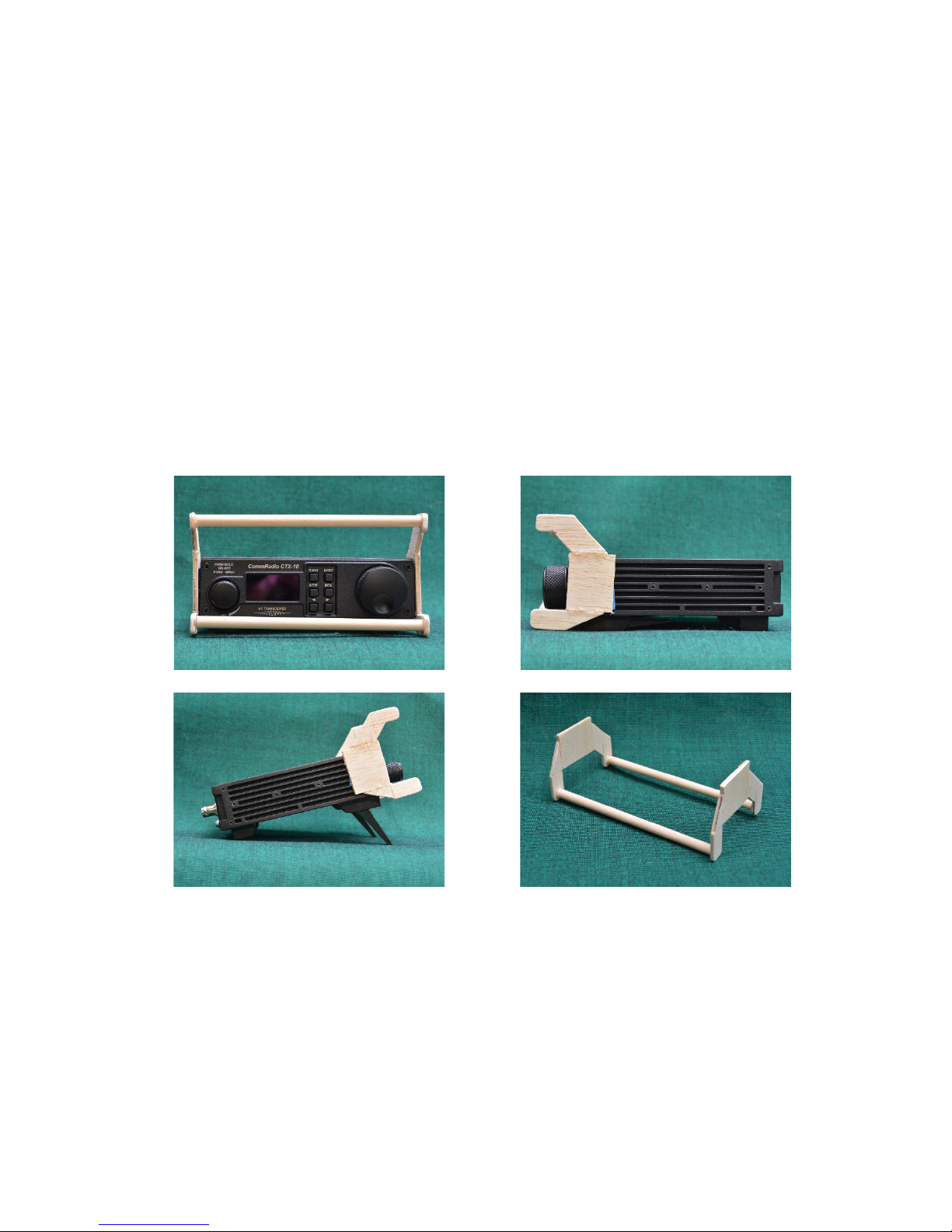
The answer of course is to provide some kind of front panel guards. Simple side-mounted
bent or flat sheet metal plates that look like equipment rack handles might do, but I found
the proximity of the Tuning Knob to be too close to the handle for my fingers to easily use.
After several trials, I came up with what I call Bar Armor, in homage to the bar armor used
to protect military vehicles from RPGs in combat zones.
What you see is glue, balsa wood and .25” diameter dowels. The armor would be secured
to the three front tapped #4-40 holes on each side of the chassis. When the radio is sitting
flat on the bench, the armor clears the bench by 1/16”, so the feet are still supporting it.
The armor will protect the front panel from impacts, prevent inadvertently turning the
radio ON, and allow the radio to be set on the bench face-down, perhaps making wiring
the rear panel easier. A similarly designed piece could also be secured to the rear of the
chassis, providing protection for the wired interconnects and cables. The front armor
could also have a strap attached on the lower front corners allowing the radio to be
carried around the neck or over the shoulder while in the field, or while climbing. The
CommRadio CTX-10 User Manual – Rev E4 - 15 NOV 2018
Page 36
36
balsa wood provided proof of concept and allowed me to evaluate the ergonomics of this
design. A production version could be made of aluminum pieces screwed together, or 3-D
printed plastic side plates with interconnecting rods. I will leave implementation of this
design to an ambitious tinkerer or entrepreneur out there.
A Peek inside the CTX-10!
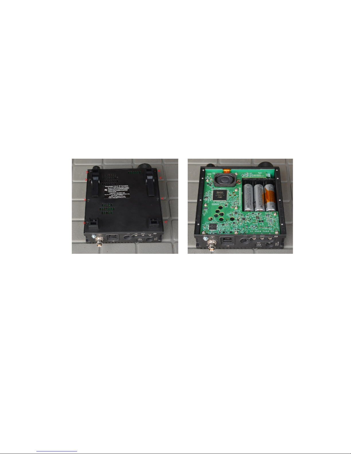
The CTX-10 is designed so that the user may remove and replace the internal batteries as
required. Three Li-Ion #18650 batteries are secured in a ruggedized socket as shown in
the right picture. To access the batteries, turn the radio upside down and lay on a soft
smooth surface, perhaps a piece of cloth. The left picture shows the location of the eight
#4-40 screws which secure the bottom plate to the die cast chassis. Each screw is adjacent
to a red arrowhead. Remove all eight screws using a #1 cross-point or Phillips
screwdriver. Carefully set the screws aside, they are easy to lose.
The batteries are press-fit into the holder, and will not readily come out. They can be
lifted using your fingers, or very carefully using a plastic tool such as a spudger, frequently
used to open cellphone cases. I do not recommend taking the batteries out without
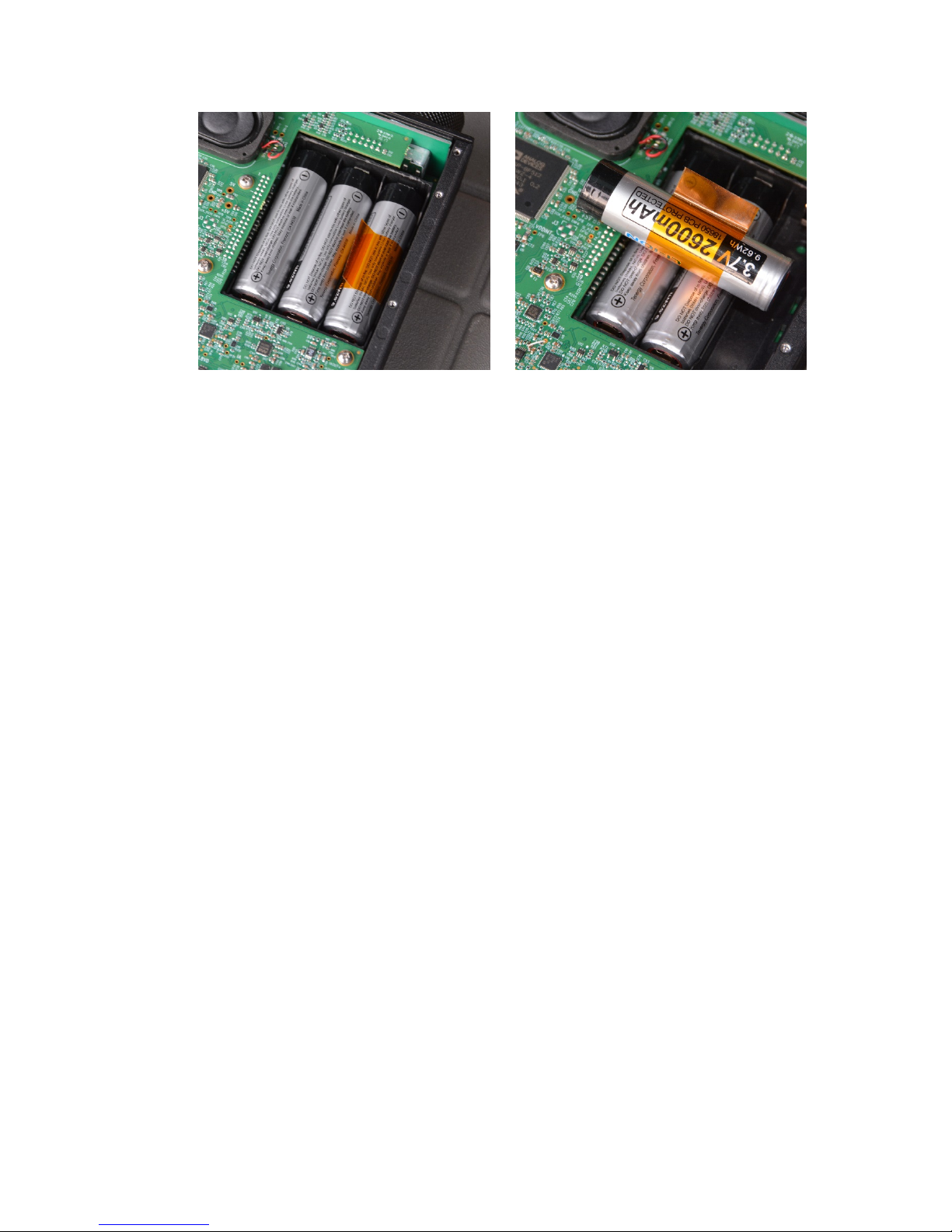
having a good reason, but when you do, I do recommend adding ‘tape handles’ to make
battery removal easier next time. Clear packing tape or other thin tape may be used, I
used a piece of Kapton tape. Start with a short, maybe 1” long tail. Wrap one loop around
the battery continuing to cover the exposed tail with the end of the tape. That’s it! From
then on, just pull each tail and the battery will follow. The pictures below provide some
detail, showing one battery with the tape handle. Note that all batteries are aligned in the
same positive-negative orientation, as is marked on the battery socket.
CommRadio CTX-10 User Manual – Rev E4 - 15 NOV 2018
Page 37
37
Ambient Noise Gate (ANG) – SSB Audio Processing
A feature unique to the CTX-10 is the Ambient Noise Gate. With the opposite functionality
of an audio compressor, the CTX-10 noise gate strongly attenuates audio signals that
register below an automatically determined threshold. What that means, is when you key
the Push-to-Talk (PTT) microphone, the transmitter is enabled. With the transmitter
enabled, the processor looks for audio coming from the microphone. If the audio level
being detected is below an automatically determined level, transmitter output is gated
OFF. When audio level being detected is above the threshold level, transmitter output is
gated ON. For normal speaking levels with a standard microphone everything works as
you would normally expect. If however, you pause for a second or two in your speech, the
output will be gated OFF, preventing background ambient noise from being transmitted.
As soon as speech is resumed, normal power output is restored. This all happens very
quickly, without any adjustments or human intervention. A beneficial effect of the ANG is
battery life will be extended slightly, depending on the particulars of an individual’s
speech pattern and ambient noise levels. The ANG feature can not be disabled.
Antenna Tuning Unit – ATU – Some details!
The standard-equipment, built-in ATU is one the features which separates the CTX-10
from many other radios. ALL ATUs use a combination of switched inductances and
capacitances to provide an impedance match between the connected antenna and the
power amplifiers. The 'secret-sauce’, the difference between various manufacturer’s ATUs
is the software – the algorithms which drive the switching functionality. The CTX-10’s
algorithm is finely tuned, yielding an optimum matching solution with a minimum of
intermediate steps.
The matching chain is as follows:
Transmitter (Power Amplifier) > Series Inductor(s) (L) > Shunt Capacitor(s) (C) > Antenna
The 6 switched-discrete-stepped Inductors can total up to 4.184 uH.
The 8 switched-discrete-stepped Capacitors can total up to 2146 pF.
The algorithm has as inputs: Vf (forward voltage), Vr (reflected voltage) and Vph (phase
voltage). The phase voltage is minimum when antenna impedance is purely resistive. As it
CommRadio CTX-10 User Manual – Rev E4 - 15 NOV 2018
Page 38

38
is impossible to actually achieve a 1:1 SWR under all conditions, a targeted 1.5:1 SWR is
deemed optimal (4% loss), with a 2.0:1 SWR being acceptable (11% loss). An operational
SWR limit set for the CTX-10 is 3.0:1 (25% loss) since this allows operation without
concern for damage to the radio. (SWRs as high as 8.0:1 during tuning will not cause
unnecessary wear and tear to the relays or circuitry since the power level during tuning is
limited to 2 W. During power down, all relays are returned to de-select condition. If the
ATU is not utilized, all relays remain in de-select condition. If a band change occurs, all
relays are returned to de-select. If the operator returns to a band where a solution is
available, the relays are returned to that selected configuration. No harm is done to the
radio by using the ATU as often as you wish. A sanity-check can be run on the ATU by
running after connecting a suitable 50 Ohm dummy load. The ATU should match at ~1:1.
CTX-10 Frequently Asked Questions (FAQ)
Q. What was the purpose of the piece of wire wrapped under the Control Knob?
A. The radio turns ON/OFF by pressing on the control knob. The wire prevents the radio
from turning ON during shipment. A similar wire, or other means should be used to prevent
the radio from turning ON when you pack the radio for travel or shipment.
Q. The rear of the radio is marked 10 – 20 VDC for power input, but the User’s Guide
says 5 – 20 VDC. Which is it?
A. The general recommendation is 10 – 20 VDC, since the current draw on the power
supply will be about 1 Ampere at 10 VDC. The radio can charge at 5 VDC but would like to
see about 2 Amperes to charge at the full rate. Lower current availability at 5 VDC will
result in longer charging times. Future chassis’ may be marked 5 – 20 VDC to eliminate
this question.
Q. When I whisper into the microphone nothing is transmitted. Is my radio broken?
A. Please refer to the Technical Notes - Ambient Noise Gate (ANG) – SSB Audio Processing
for details.
Q. How should I clean and protect the finish of my radio?
A. The chassis is finished with a very durable powder coated paint finish. Surface dust can
be removed with a slightly dampened soft cloth. Dust in the external heatsink grooves on
the chassis can be removed with a dry or slightly dampened soft paint brush which will get
to the bottom of the grooves. I can recommend a product such as 303 (30308) Aerospace
Protectant for Plastic, Vinyl and Rubber (or equivalent) available from Walmart. Use this
to slightly dampen the cloth or paintbrush. These products should not leave a film or
coating on the chassis. I do not recommend Armor All as I’ve found it leaves a nasty film
that never seems to go away. Never spray any finish directly on the chassis. Use only a dry
cloth or a LensPen (like you use on your camera lens) on the display screen. Treat your
radio like you would your camera or binoculars.
CommRadio CTX-10 User Manual – Rev E4 - 15 NOV 2018
Page 39

39
Q. How do I ‘Zero Beat’ an incoming CW signal that I want to answer?
Transmit Bands: 80, 60, 40, 30, 20, 17, 15, 12, 10 meters (no 160m)
A. The sidetone produced by the CTX-10 when transmitting CW is at an offset from the
actual transmitting frequency. If you adjust the received signal’s pitch to be the same as
the sidetone pitch, you will be transmitting on the same frequency as the station you are
receiving. This is sometimes called Zero Beating, or more accurately Sidetone Matching.
CTX-10 Specifications
Transmit Modes: USB/LSB/CW/Data (sound card) (no AM, no FM)
RF Power Output: 1, 5 or 10 Watts
Receive Coverage: 150 kHz - 30 MHz
Receive Modes: USB/LSB/CW/AM
Receive Bandwidths: AM 5/7.5/15 kHz; SSB 1.8/2.2/2.6 kHz; CW 0.5/1/1.8/2.2/2.6 kHz
Receive Auto Bandwidths: AM 5/7.5/15 kHz; SSB 1.8/2.6 kHz; CW 1/0.5 kHz
Pre-Selectors: .15-.54, .54-1.71, 1.7-4, 4-7.5, 7.5-14.5, 14.5-21, 21-30.0 MHz
Tuning Resolution: 1MHz, 100, 10, 1 kHz, 100, 10 Hz.
Sensitivity MDS: Above 1.800 MHz: -135 dBm ( 500 Hz CW) Sensitivity SSB: -110 dBm
(2600 Hz SSB) Below 1.800 MHz: -115 dBm ( 500 Hz CW)
Audio System: 0.8 watts @ 8 Ohm to 1.2 x 1.6" Internal Speaker or External Speaker jack
AGC Attack Time: Slow/Medium/Fast/Off
Antenna Input: BNC 50 Ohm
Display Type: OLED 64 x 128 1.5" diagonal, EMI coated glass protective cover installed
DC Power Jack: 5 - 20 VDC 2.5 x 5mm, center positive. 20 VDC absolute maximum.
DC Power: 5 – 20 VDC Normal charging draws with power OFF: 10 -12 W. Current
required is a function of voltage. Examples: 12 VDC ~1 A, 18 VDC ~0.65 A, 5 VDC ~2 A.
CommRadio CTX-10 User Manual – Rev E4 - 15 NOV 2018
Page 40

40
Batteries: 3 pc. #18650 Li-ion 4.2 V @2.6 Ah (each)
USB Mini-B 2.0 Jack: Firmware updates, I-Q data & radio control, Windows spectrum
scope. No power input or output from mini-USB jack.
ESD Protection: ESD diodes at antenna, power jacks, USB port, keys and knobs.
Physical: Size: 5.61”W x 1.55”H x 6"D Weight: 2.2 lbs.
CommRadio CTX-10 User Manual – Rev E4 - 15 NOV 2018
Page 41
1 150 - 550 KHz
2 540 - 1710 KHz
3 1.7 - 4.0 MHZ
4 4.0 - 7.5 MHZ
5 7.5 - 14.5 MHZ
6 14.5 - 21.0 MHZ
7 21.0 - 30.0 MHz
7x Band Pass Filter
Pre-Selector
Auto-Switched
y y
VV VV
V
REF
V
FWD
V
PH
Dual
PLL
XMTR
CODEC
CW Bypass
IQ
IQ
249.0 MHz
83.0 MHz
HF+83.0 MHz
19.2
MHz
19.2
MHz
19.2
MHz
19.2
MHz
FTDI
UART
USB
19.2
MHz
ACC. JACK
AUDIO (DATA) IN
EXT’L MIC IN
=
DDS
T
R
BNC
ADC
ADC
DSP
PIC 24F
24 MHZ CLOCK
RCVR
CODEC
FLASH
RAM
INTERNAL
SPEAKER
ACC. JACK
AUDIO (DATA) OUT
EXTERNAL
NON-AMPLIFIED
SPEAKER
Optical Tuning
Knob [T] and Switch
Master Distributed
Frequency Reference
0.2 ppm TCXO
D
HEADPHONES
Control Knob [M]
and Switch
Keypad
6 position
CW Key / Paddles
Accessory Jack
GPIO / RELAY &
SWITCH CONTROL
FRONT PANEL
OLED DISPLAY
c
6x
8x
V
ATU
Switched L-Section
Band
Switched
Low Pass
Filters
Directional
Coupler
Ø
Phase
Detector
1 1 1
5
9
13
3
7
11
15
2
6
10
14
17
4
8
12
16
PWR
MGMT
e
in
e
out
e
in
= 5 to 20 VDC @ 12W
SYSTEM BUS
3x #18650 Li-ion
2.6 Ah Internal Battery
3.7 VDC nominal,
4.2 VDC max. full charge
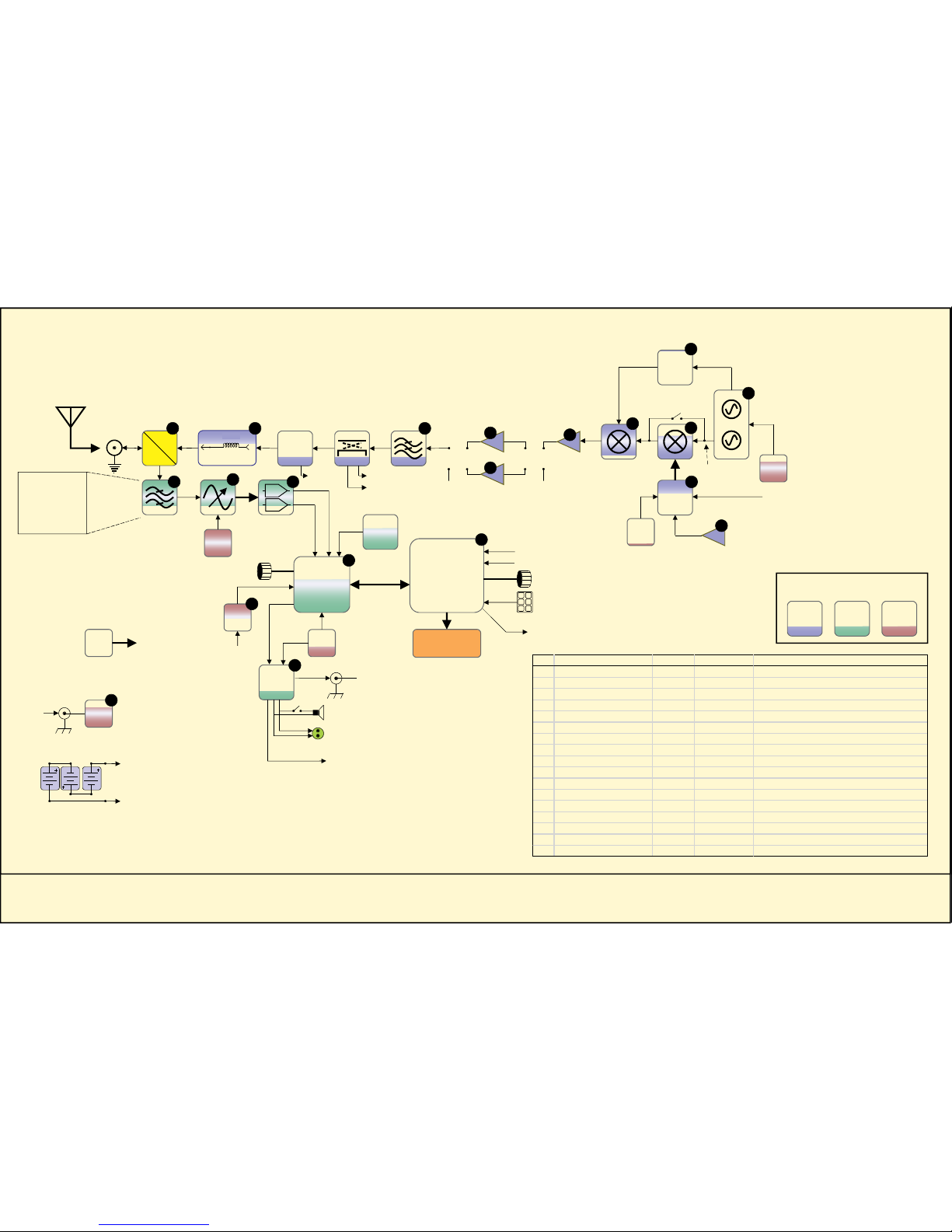
ITEM DESCRIPTION VENDOR P/N NOTES
1 T/R Switch, RF PWR Switch Omron G6JU-2P-Y T/R Relay, 5x TX LPF, 14x ATU
2, 3 Output Power Transistor NXP AFT05MS006N 6W Wideband RF Power LDMOS
4 Driver Transistor NXP AFT05MS003N 3W Wideband RF Power
5 Mixer Linear/AD LT5560 Low Power Active Mixer
6 Direct Digital Synthesizer AD AD9913 Low Power DDS
7 Mixer Linear/AD LTC5599 Low Power Direct Quadrature Modulator
8 Dual Phase Locked Loop AD ADF4360-9 Clock Generator PLL with Integrated VCO
9 Transmitter CODEC TI TLV320AIC3254 Ultra Low Power Audio CODEC & miniDSP
10 Microphone PreAmp AD SSM2167 Microphone PreAmp / Compression / Noise Gate
11 RF Tuner Mirics MSi00x Multi-mode RF Tuner
12 Dual 14 bit ADC Linear/AD LTC140 7 Rx > DSP
13 Digital Signal Processor AD BF512 Blackfin Embedded Processor
14 PIC Microcontroller M icrochip PIC24 16 bit microcontroller
15 FTDI UART FTDI FT2 31XQ USB to Full Handshake UART
16 Receiver CODEC Cirrus WM8960 (Wolfson) Stereo CODEC & Speaker Driver
17 Rx Solid State Switch Peregrine PE4259 Rx BPF, 2 @ per band
18 PWR Management Linear/AD LTC4020 Buck/Boost Battery Charger Controller
18
CommRadio
CTX-10 Amateur Radio Transceiver
Funconal Block Diagram
Copyright 2018
CommRadio div. AeroStream Communicaons
All rights Reserved
No poron of this manual may be reproduce d without
permission of CommRadio / AeroStream Co mmunicaons
REV. PRELIMINARY 5 APR 2018
CTRLRCVRXMTR
LEGEND
 Loading...