

Page 1

CommPower CP-145 Gateway
User’s Guide
C O M M
P O
W
E R
US e-Mail™
Document Part #: /cpe/CP-145/usm/004
Page 2
C O M
M
P O
W
E R
Revision History:
Date
Document Revision
June 2003
001 September 2004
002 December 2005
003 July 2014
004
Document Part Number and Revision:
CP-145 Gateway - Users Guide
Document Part Number: /cpe/CP-145/usm/004
This document describes how to start up and operate the ACP-145.
Copyright Notice:
Copyright 2002, 2003, 2004, 2005, 2006, 2007, 2008, 2009, 2010, 2011, 2012,
2013, 2014 Communications & Power Engineering, Inc.
All rights reserved. No part of this publication may be reproduced, transmitted,
stored in a retrieval system, nor translated into any human or computer language,
in any form or by any means, electronic, mechanical, magnetic, optical, chemical,
manual, or otherwise, without the prior written permission of the copyright
owner, Communications & Power Engineering, Inc. Copyright infringement is a
serious matter under the United States and foreign Copyright Laws.
Any copyrighted software that accompanies this document is licensed to the End
User only for use in strict accordance with the governing End User License
Agreement (EULA), which should be read carefully before commencing use of
the software. Information in this document is subject to change without notice.
Use, duplication, or disclosure by the UNITED STATES GOVERNMENT is
subject to restrictions as set forth in subparagraph (c) (1) of the COMMERCIAL
COMPUTER SOFTWARE - RESTRICTED RIGHTS clause at FAR 52.22719, or subparagraph (c) (1) (ii) of the RIGHTS IN TECHNICAL DATA AND
COMPUTER SOFTWARE clause at DFARS 52.227-7013. The
“Contractor/Manufacturer” is Communications & Power Engineering, Inc.
CommPower, Inc.
850 Calle Plano, Suite K
Camarillo, CA 93012
Telephone: 1 805 389 7414
e-Mail: Internet ([email protected])
Page 3

CP-145 GATEWAY USER’S GUIDE
TABLE OF CONTENTS
CHAPTER 1
OVERVIEW ......................................................... 1-1
CHAPTER 2
STARTUP, SHUTDOWN, AND GENERAL OPERATING
PROCEDURES 2-1
CHAPTER 3
SYSTEM MENU ................................................... 3-1
1.1 PRODUCT OVERVIEW ...................................................................... 1-1
1.2 DOCUMENT OVERVIEW ................................................................. 1-3
1.3 other related documents .......................................................................... 1-3
2.1 CP-145 STARTUP AND SHUTDOWN ............................................ 2-1
2.1.1 CP-145 Startup .............................................................................. 2-1
2.1.2 CP-145 Shutdown .......................................................................... 2-1
2.2 GENERAL OPERATING PROCEDURES ..................................... 2-1
2.2.1 The Menu Bar ................................................................................. 2-2
2.2.2 The Tool Bar ................................................................................... 2-3
2.2.3 The Main Window Display Area .................................................... 2-4
2.2.4 The Status Bar ................................................................................ 2-7
3.1 CHANNEL Operations .......................................................................... 3-2
3.2 STATUS ................................................................................................. 3-19
3.3 ALARMS ................................................................................................ 3-20
3.4 Warnings ................................................................................................. 3-21
3.5 EVENTS ................................................................................................ 3-22
3.6 STATISTICS ......................................................................................... 3-31
3.7 REPORTS .............................................................................................. 3-32
3.1.1 Open Channel ................................................................................. 3-3
3.1.2 Close Channel ................................................................................. 3-3
3.1.3 Display Channel Parameters ............................................................ 3-3
3.1.4 Set up Channel Parameters .............................................................. 3-7
3.1.5 Define Channel Capability Bits ..................................................... 3-17
3.1.6 Halt Output to a Channel ............................................................. 3-18
3.1.7 Release Channel Halt .................................................................... 3-19
3.5.1 Event Profile .................................................................................. 3-22
3.5.2 Configure Event Text Colors ......................................................... 3-26
3.5.3 Printer ........................................................................................... 3-29
3.5.4 Alarm Sound Setup ....................................................................... 3-30
3.7.1 System Report ................................................................................ 3-34
3.7.2 Single Channel Report ................................................................... 3-35
3.7.3 All Channels Report...................................................................... 3-36
3.7.4 Event Log Report .......................................................................... 3-37
3.7.5 Live Messages Report ..................................................................... 3-38
/cpe/CP-145/usm/004 (07/14) ~ i ~
Page 4

ACP-145 Gateway User's Guide
CHAPTER 4
MESSAGE MENU ................................................. 4-1
CHAPTER 5
ROUTING MENU.................................................. 5-1
CHAPTER 6
VIEW MENU ........................................................ 6-1
CHAPTER 7
HELP MENU ...................................................... 7-1
CHAPTER 8
TOOLS AND UTILITIES ........................................ 8-1
3.7.6 Security Log Report ....................................................................... 3-38
3.8 archive operations ................................................................................. 3-39
3.8.1 Set Purge Age ................................................................................ 3-40
3.8.2 Purge Archive ................................................................................ 3-40
3.9 PREFERENCES .................................................................................. 3-41
3.9.1 Disk Threshold ............................................................................. 3-41
3.9.2 Command Wait ............................................................................ 3-42
3.10 VIEW CONFIG FILE ........................................................................ 3-42
3.11 SYSTEM SHUTDOWN ..................................................................... 3-43
3.12 EXIT ....................................................................................................... 3-44
4.1 archive ........................................................................................................ 4-1
4.2 Purge ....................................................................................................... 4-15
4.3 Error Queue ........................................................................................... 4-16
5.1 ADDress Book ......................................................................................... 5-1
5.2 View Routing Map/Errors ..................................................................... 5-5
5.3 DEFAULT ROUTINGS ....................................................................... 5-6
6.1 Large icons ................................................................................................ 6-1
6.2 text .............................................................................................................. 6-1
6.3 TOOL BAR .............................................................................................. 6-2
6.4 Clear display Area ..................................................................................... 6-2
4.1.1 “Filter” Message UID Retrieval based on Time Range ................... 4-5
4.1.2 Retrieve by Message ID .................................................................... 4-7
4.1.3 View Message ................................................................................ 4-11
4.1.4 View Events .................................................................................. 4-11
4.1.5 Retransmit Message ....................................................................... 4-12
4.1.6 Cross Reference IDs ....................................................................... 4-12
4.3.1 View Message in MEQ ................................................................ 4-17
4.3.2 Delete Message in MEQ ............................................................... 4-18
5.1.1 Display Collective and User Name Records ...................................... 5-2
~ ii ~ /cpe/CP-145/usm/004 (07/14)
7.1 ABOUT ..................................................................................................... 7-1
7.2 Help ............................................................................................................ 7-1
8.1 Cache Utility .............................................................................................. 8-1
8.2 Clear Logs Tool ........................................................................................ 8-4
8.3 Map System Utility ................................................................................... 8-5
8.1.1 Cache Utility Startup ...................................................................... 8-1
8.1.2 Cache Utility Operation ................................................................... 8-3
8.3.1 Map System Utility Startup ............................................................. 8-5
Page 5

Table of Contents
APPENDIX A
EVENT MESSAGES ............................................... A-1
APPENDIX B
TROUBLESHOOTING/SYSTEM TIPS...................... B-1
APPENDIX C
REPORT DETAIL ................................................. C-1
8.3.2 Map System Utility Operation ......................................................... 8-6
8.3.3 Map System Utility Shutdown ......................................................... 8-8
8.4 Message Recovery Utility ........................................................................ 8-8
8.4.1 Find Message Option ..................................................................... 8-10
8.4.2 Save Message List to File Option ................................................... 8-11
8.5 Queue Monitor Utility .......................................................................... 8-12
8.5.1 Queue Monitor Startup .................................................................. 8-12
8.5.2 Queue Monitor Operation .............................................................. 8-14
8.5.3 Queue Monitor Shutdown .............................................................. 8-15
B.1 TROUBLESHOOTING/SYSTEM TIPS ......................................... B-1
C.1 SYSTEM TRAFFIC ACTIVITY REPORT ...................................... C-1
C.2 CHANNEL TRAFFIC ACTIVITY REPORT ................................. C-6
C.3 EVENT LOG REPORT ....................................................................... C-8
B.1.1 System Won’t Start ........................................................................ B-1
B.1.2 Messages Are Re-released Automatically At System Startup ........... B-1
B.1.3 Clear Error Log Files .................................................................... B-2
B.1.4 Clear Event Log Files, Statistics Log Files, and The Message ArchiveB-2
B.1.5 Messages Are Not Input/Output From/To The MTA ................. B-2
B.1.6 Configuration Changes Are Not Implemented ................................. B-3
/cpe/CP-145/usm/004 (07/14) ~ iii ~
Page 6
Chapter 1
OVERVIEW
1.1
PRODUCT OVERVIEW
This document describes how to use the CommPower CP-145 Gateway (CP-
145). The CP-145 is designed to run in the Windows 2008 R2 Server
operating environment and features user-friendly menus and dialogs that let
you configure, monitor, and control CP-145 operations.
Throughout the world, e-mail based Military Messaging services have
become an integral component of a modern Defense Command and Control
infrastructure, providing the means through which commanders at all levels
can effectively and securely communicate orders, instructions, and strategies.
Unfortunately, true globalization of such services has not and probably
cannot be realized due to differences in national implementations and the
lack of a common end-to-end security policy. The CCEB (Combined
Communications Electronics Board) has recognized this shortcoming and in
response, has drafted a standard (CP-145) that details the requirements and
functions of a nation-to-nation Military Messaging Gateway based on
ACP123/X.400 technology and S/MIME-ESS security services. In turn,
CommPower has taken this standard from paper to practice with the
introduction of its CP-145 Gateway product.
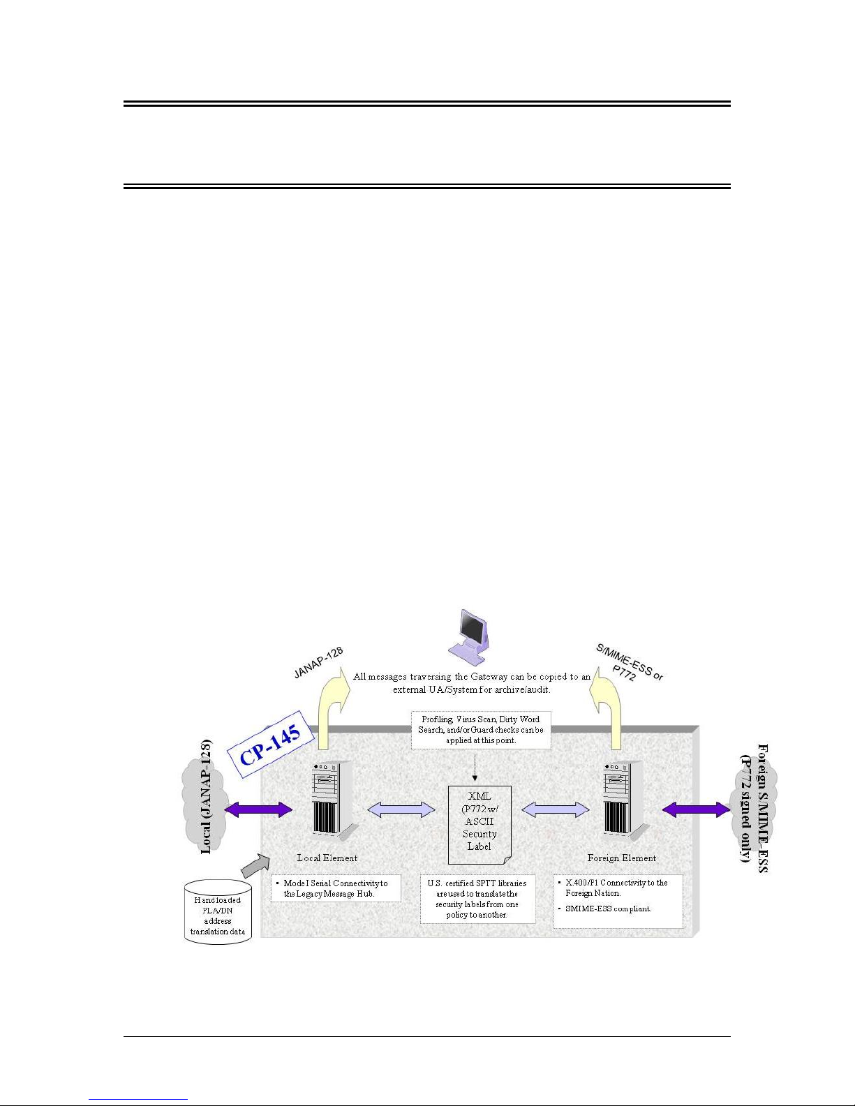
The CP-145 Gateway consists of two subsystems, or "Elements", one for
handling JANAP-128 messages and one handling SMIME-ESS P772
/cpe/CP-145/usm/004 (07/14) 1-1
Page 7

ACP-145 Gateway User's Guide
messages. The Local Element provides connectivity to a local JANAP-128
messaging host via a dedicated Mode I serial connection, whereas the
Foreign Element connects to the external network of the foreign nation.
Messages received/transmitted on each network interface are processed in
full per the security policy that governs the domain represented by the CP145 Element.
• Supported Security Standards: The security standards supported within
the Gateway include: S/MIME-ESS (Extended Security Services).
• Security Policy Definition: Security Policy Information Files (SPIFs) can
be created for each security domain that define the security policy in
effect and enforce access control. Multiple policies can be supported for
each security domain.
• Security Label Translation: User configurable Security Policy Translation
Tables (SPTTs) are used within the Gateway that defines the security
label translation rules between differing security policies. These tables are
loaded from a configurable location on disk.
Message flow within the Gateway between the discrete Elements is
accomplished via XML services that promote standardization, commerciality,
and extensibility within the product. Core features of the CP-145 include the
following:
• Virus Checking: Third party anti-virus products can be invoked by the
CP-145 to scan in-transit messages and their attachments for malicious
content.
• Message Services: As with all CommPower Military Messaging products,
the CP-145 offers full protection, accountability, and recovery for all
messages within the Gateway.
• Third Party Services: Third party capabilities such as profilers can be
installed "in line" to perform additional processing on the XML message
as it passes through the Gateway.
• Extensibility: Because of the Gateway's modular architecture, a host of
configurations can be realized to allow connectivity to one or more
nations, each with a separate security translation policy.
The CommPower CP-145 Gateway product was selected by the U.S.
Department of Defense as the sole provider of CP145 Gateway services for
its Defense Message System (DMS) program.
1-2 /cpe/CP-145/usm/004 (07/14)
Page 8

1.2
DOCUMENT OVERVIEW
1.3
OTHER RELATED DOCUMENTS
CP-145 Installation and Administration Manual:
This document describes the operation of the CP-145 in the following
chapters and appendices:
Chapter 1, Overview: This chapter provides an overview description of the
CP-145 and this document.
Chapter 2, Startup, Shutdown, and General Operating Procedures: This
chapter describes CP-145 startup, shutdown, and general operating
procedures. It also contains a menu tree and a reference table that can be
used as a navigation tool for selecting items in the menus.
Chapter 3, System Menu: This chapter describes the options in the System
Menu: Channel Operations, Status, Alarms, Warnings, Events, Statistics,
Reports, Archive Operations, Preferences, View Config File, Shutdown, and
Exit.
Chapter 4, Message Menu: This chapter describes the options in the
Message Menu: Archive, Purge, and Error Queue.
Chapter 5, Routing Menu: This chapter describes the options in the
Routing Menu: Address Book (CP-145 Local Element only), View Routing
Map/Errors, and Default Routings.
Chapter 1. Overview
Chapter 6, View Menu: This chapter describes the options in the View
Menu: Large Icons, Text, Tool Bar, and Clear Display Area.
Chapter 7, Help Menu: This chapter describes the options in the Help
Menu: About and Help.
Chapter 8, Tools and Utilities: This chapter describes the tools and utilities
that are installed with CP-145 application software: Cache Utility, Card
Control, Clear Logs, Map System, Message Recovery, and Queue Monitor.
Appendix A, Event Messages: This appendix includes a list of CP-145 event
messages.
Appendix B, Troubleshooting/System Tips: This appendix describes
troubleshooting tips that can be used to recover from problem conditions
and some general tips that can be used to help maintain the CP-145 system.
Appendix C, Report Detail: This appendix provides a detailed description of
the System Traffic Activity Report, Channel Traffic Activity Report, and
Event Log Report.
For additional information about the CP-145, refer to one or more of the
following documents:
how to install the CP-145 system and provides technical system information.
/cpe/CP-145/usm/004 (07/14) 1-3
This document describes
Page 9

ACP-145 Gateway User's Guide
C
O M
M
P O
W
E
R
1-4 /cpe/CP-145/usm/004 (07/14)
Page 10

Chapter 2
STARTUP, SHUTDOWN, AND GENERAL
OPERATING PROCEDURES
2.1
CP-145 STARTUP AND SHUTDOWN
2.1.1 CP-145 Startup
2.1.2 CP-145 Shutdown
2.2
GENERAL OPERATING PROCEDURES
This chapter describes startup, shutdown, and general operating procedures
for the CP-145 Gateway.
To start up the CP-145 Gateway, select Start >>All Programs>>ACP-145
Gateway >>Start CP-145. The CP-145 Startup Monitor will be displayed
and as each start up process completes, the button will turn green indicating
success. The CP-145 Status Indicator will appear (multi-colored Icon) in the
bottom right-hand corner of the desktop. The indicator will initially flash
different colors during startup. It will stop changing color once the CP-145
Gateway is online. At this point, the User Interface can be started by
selecting the User Interface button on the CP-145 Start Monitor, selecting
Start >> All Programs>>ACP-145 Gateway >>User Interface or by
placing the cursor on the CP-145 Status Indicator, right clicking the mouse,
and selecting User Interface from the resulting pop-up menu.
If the CP-145 startup is unsuccessful, the CP-145 Gateway Status Indicator
will continue to flash, and an Error dialog will be displayed indicating that
the CP-145 was terminated due to an error condition of unknown origin. If
this condition occurs, please refer to the troubleshooting tips in Appendix B.
To shutdown the CP-145 from the User Interface select “System” then
“System Shutdown.” Select the Yes button in the confirmation dialog. The
CP-145 can also be shutdown by placing the cursor over the CP-145 Status
Indicator, right clicking the mouse and selecting Stop CP-145 from the
resulting pop-up menu. Select the Yes button in the subsequent
confirmation dialog. Either shutdown option will bring down the User
Interface and stop the CP-145 application
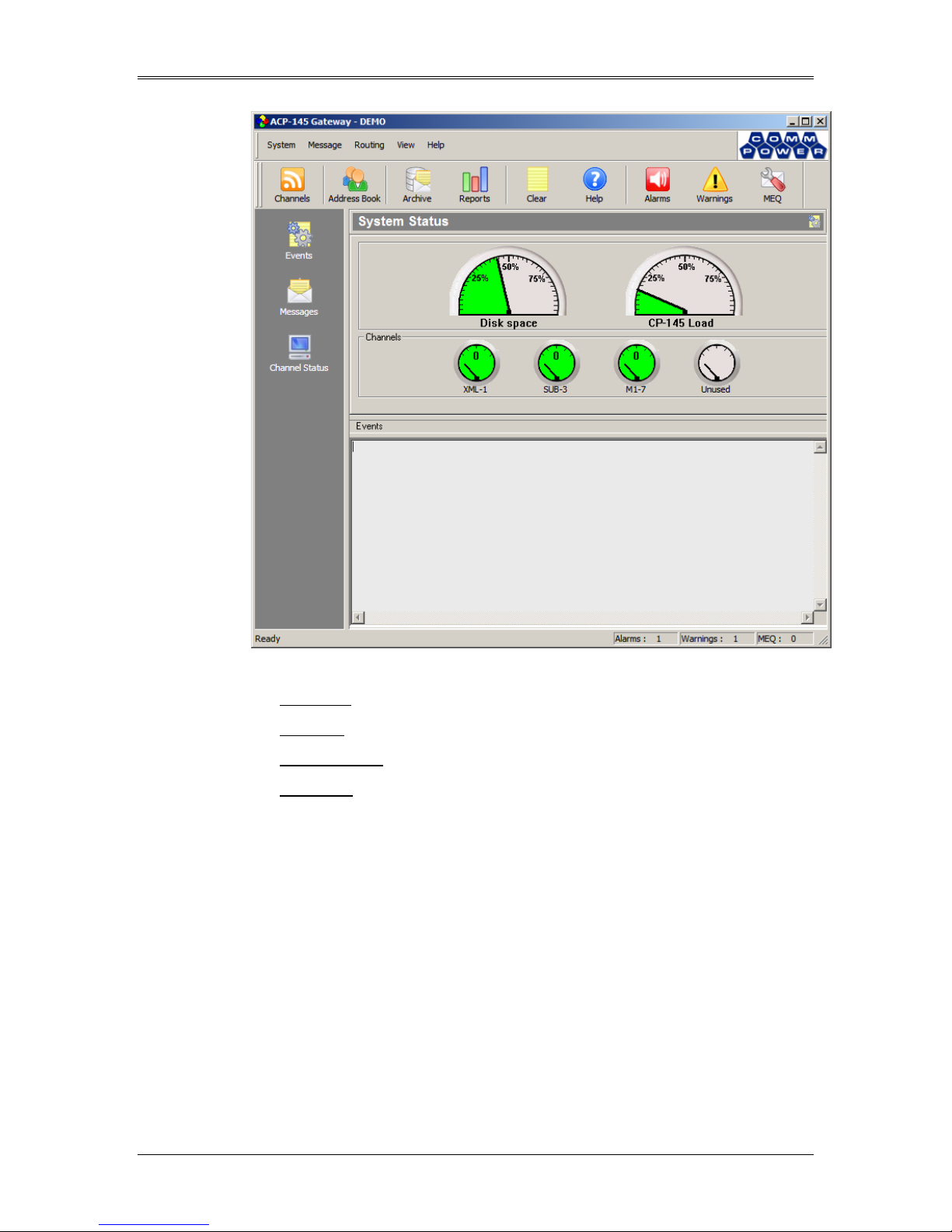
Following successful startup of the CP-145 User Interface, the CP-145 Main
Window is displayed:
NOTE: The Address Book and MEQ buttons on the Toolbar are only
present on the CP-145(L).
/cpe/CP-145/usm/004 (07/14) 2-1
Page 11
ACP-145 Gateway User's Guide
2.2.1 The Menu Bar
The CP-145 Main Window consists of these sections:
Menu Bar (drop down menus across the top of the window)
Tool Bar (icon buttons below the Menu Bar)
Main Window display area and control buttons (below the Tool Bar)
Status Bar (across the bottom of the window)
The Menu Bar across the top of the window is used to select and execute
menu options:
System (See Chapter 3)
Messages (See Chapter 4)
Routing (See Chapter 5)
View (See Chapter 6)
Help (See Chapter 7)
These menus are described in the remaining chapters of this manual. A menu
tree is included at the end of this chapter.
2-2 /cpe/CP-145/usm/004 (07/14)
Page 12
Chapter 2. Startup, Shutdown, and General Operating Procedures
2.2.2 The Tool Bar
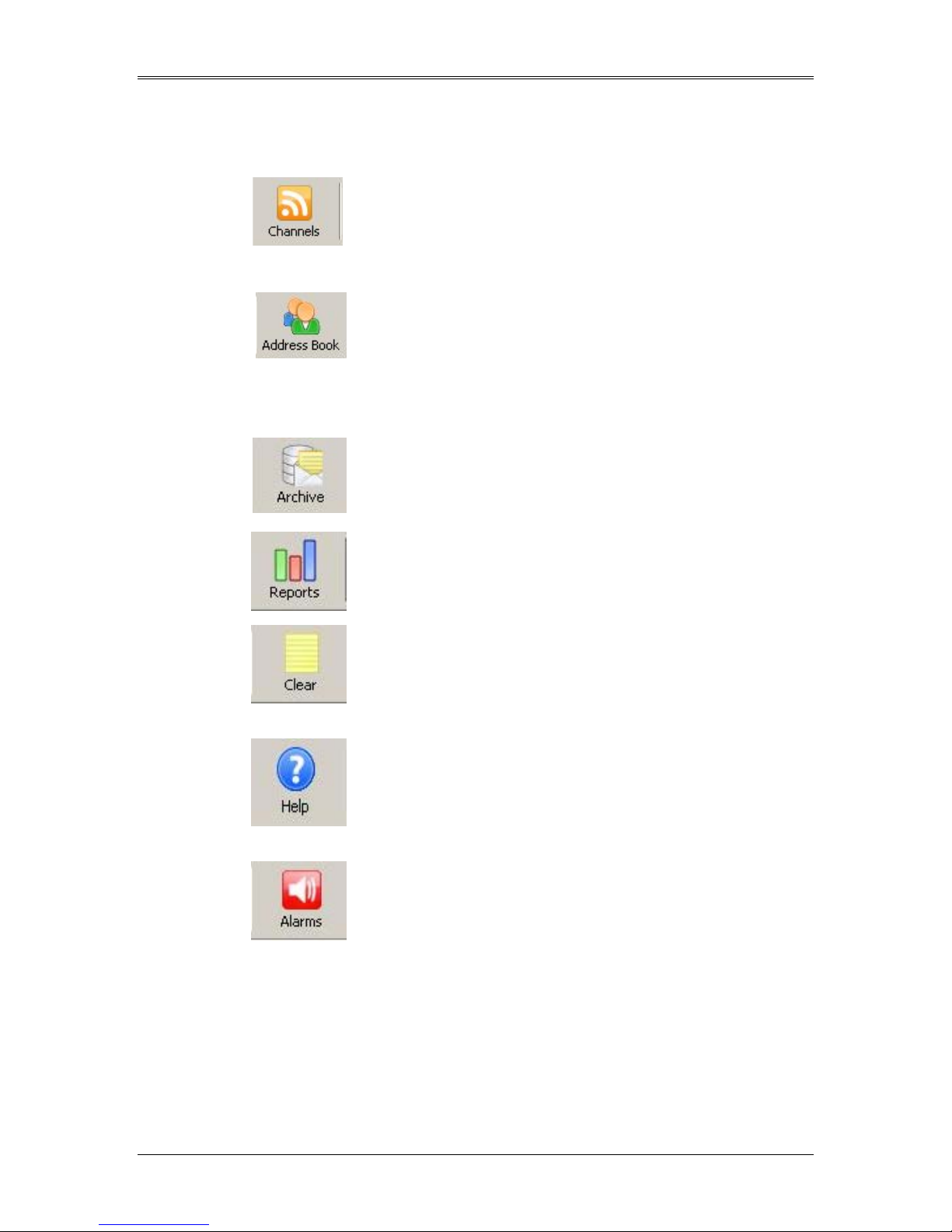
The Tool Bar provides quick access to these buttons:
The Channels button, which is the left-most button, provides
quick access to the Channel Operations dialog. This is
equivalent to selecting Channel Operations from the
System/Channels sub-menu. See “Channel Operations” in
Chapter 3.
The Address Book button, which is the second button from
the left, provides quick access to the Address Book dialog.
This is equivalent to selecting Address Book from the
Routing Menu. See “Address Book” in Chapter 5.
NOTE: The Address Book functionality is only applicable to the CP-
145(L).
The Archive button, which is the third button from the left,
provides quick access to the Message Archive dialog. This is
equivalent to selecting Archive from the Message Menu. See
“Archive” in Chapter 4.
The Reports button, which is the fourth button from the left,
provides quick access to the Reports dialog. This is equivalent
to selecting Reports from the System Menu. See “Report” in
Chapter 3.
The Clear button, which is the fifth button from the left,
removes scrolled event/message related information from the
CP-145 Main Window display area. This is equivalent to
selecting Clear Display Area from the View Menu. See “Clear
Display Area” in Chapter 6.
The Help button, which is the sixth button from the left,
provides quick access to CP-145 Help script. This is
equivalent to selecting Help from the Help Menu. See
Chapter 7.
The Alarms button, which is the seventh button from the
left, provides quick access to the Alarm Message dialog. This
is equivalent to selecting Alarms from the System Menu.
Alarms are operator notifications of potentially serious
conditions that have occurred within the CP-145. When alarms are
generated, they are queued to the Alarms field (in the bottom right-hand
corner of the CP-145 Main Window) to alert the operator of the condition.
In addition, if audible alarms have been assigned to alarm notifications via
the Audible Alarm Setup option, then the Alarms button will oscillate when
these alarms occur. See “Alarms” and “Audible Alarm Setup” in Chapter 3.
/cpe/CP-145/usm/004 (07/14) 2-3
Page 13
ACP-145 Gateway User's Guide
2.2.3 The Main Window Display Area
The Warnings button, which is the eighth button from the
left, provides quick access to the Warning Message dialog. This
is equivalent to selecting Warnings from the System Menu.
Warnings are operator notifications of less serious conditions
that have occurred within the CP-145. When warnings are generated, they
are queued to the Warnings field (in the bottom right-hand corner of the CP145 Main Window) to alert the operator of the condition. In addition, if
audible alarms have been assigned to warning notifications via the Audible
Alarm Setup option, then the Warnings button will oscillate when these
warnings occur. See “Warnings” and “Audible Alarm Setup” in Chapter 3.
The Tool Bar can be removed from the CP-145 Main Window, if desired, by
deselecting the Tool Bar sub-menu option in the View Menu. See Chapter 6.
The Tool Bar can also be moved to another location. To do this, place the
cursor on the parallel bars (or handles) to the left of the Channels button,
and then click on and drag the Tool Bar to the desired location. (When
moving it to either side, i.e., directly below its current location, its orientation
changes from horizontal to vertical so that it can be “docked” in a nonintrusive location.) Any new location is retained upon exiting and returning
to the CP-145 Main Window.
The Message Error Queue (MEQ) button, which is the nineth
button from the left, provides quick access to the MEQ dialog. This is
equivalent to selecting MEQ from the System Menu. Messages that the CP145(L) cannot route are sent to the MEQ. Certain errors, service messages,
and non-delivery reports can be configured to be sent to the MEQ. See
“MEQ” in Chapter 3.
The Main Window display area consists of a window for displaying pertinent
operator-related information and three buttons for controlling the type of
information displayed. These buttons include:
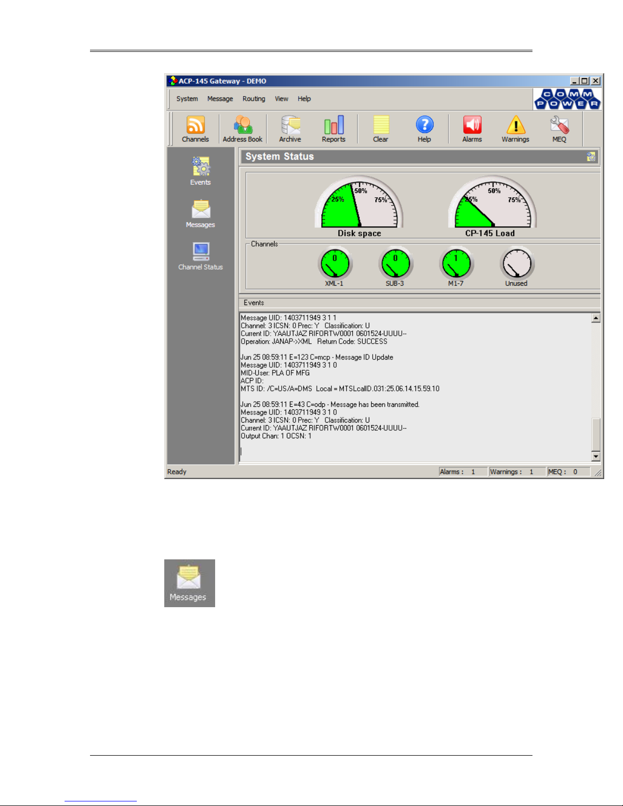
The Events button, which is the top-most button, enables the
display of event messages. When the button is selected, the label
associated with the CP-145 Main Window display area changes
to Events to acknowledge button selection and event messages
currently being generated are displayed:
2-4 /cpe/CP-145/usm/004 (07/14)
Page 14
Chapter 2. Startup, Shutdown, and General Operating Procedures
The information provided for each event is contingent upon the type of the
event. However, all events include the operating system date and time that
the event message was generated; the number assigned to the event message
(“E=number”); the name of the process generating the event (“C=process
name”); and the event message text.
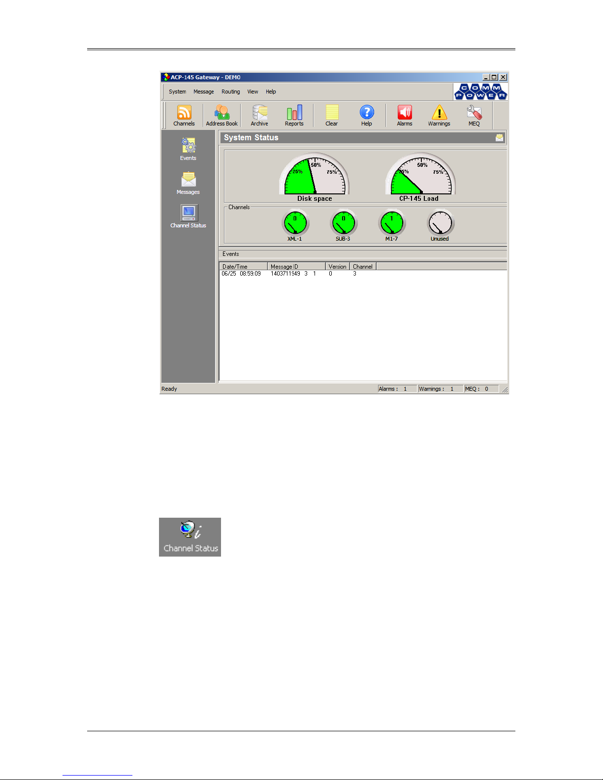
The Messages button, which is the second button from the
top, displays incoming message information. When the button
is selected, the label associated with the Main Window display
area changes to Messages to acknowledge button selection and a
list of messages that have passed through the CP-145 since the User
Interface was started is displayed:
/cpe/CP-145/usm/004 (07/14) 2-5
Page 15
ACP-145 Gateway User's Guide
The information provided for each message includes the operating system
date and time that the message was received; the Message ID that was
assigned to the message; the version number of the message; and the channel
that received the message. Double clicking a message Date/Time value will
cause the system to create a Message Journal Report for the selected
message. A Message Journal Report contains all Event Messages associated
with the message.
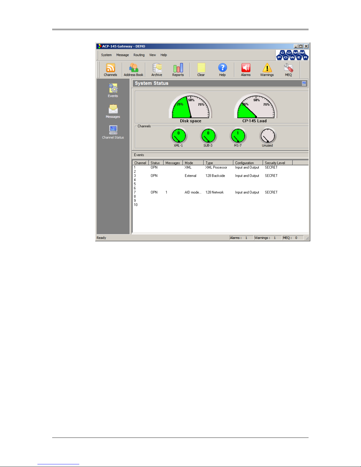
The Status button, which is the bottom-most button, enables
the display channel status for all configured channels. When
the button is selected, the label associated with the CP-145
Main Window display area changes to Status to acknowledge button
selection and the current status is displayed for all channels:
2-6 /cpe/CP-145/usm/004 (07/14)
Page 16
Chapter 2. Startup, Shutdown, and General Operating Procedures
2.2.4 The Status Bar
The information provided for each channel includes the channel number; the
current status of the channel; the number of messages currently queued to
the channel; and the channel mode, type, configuration, and security level.
Status values include “OPN” (Open), “CLO” (Closed), “HLT” (Halted),
“CIT-<n>” (Channel Intercept, where n equals the specified precedence
level); and blank for undefined channel. With respect to defined (or
configured) channels, if a channel is closed, “CLO” is displayed; if it is open
and halted, “HLT” is displayed; if it is open and has precedence intercept set,
“CIT-<n>” is displayed; if it is open and is neither halted nor has precedence
intercept set, “OPN” is displayed; if it is open and is both halted and has
precedence intercept set, “HLT” is displayed.
The Status Bar across the bottom of the window includes an area for status
messages (on the left) and the following two fields:
Alarms
Warnings
MEQ
/cpe/CP-145/usm/004 (07/14) 2-7
Page 17

ACP-145 Gateway User's Guide
The Alarms field indicates the current number of alarms. As stated above,
alarms are operator notifications of potentially serious conditions that have
occurred within the CP-145. They can be displayed by selecting the Alarms
button (in the Tool Bar).
The Warnings field indicates the current number of warnings. As stated
above, warnings are operator notifications of less serious conditions that
have occurred within the CP-145. They can be displayed by selecting the
Warnings button (in the Tool Bar).
The MEQ field indicates the current number of messages on the MEQ. As
stated above, messages on the MEQ are service messages, non-delivery
reports, or messages with format errors. They can be displayed by selecting
the MEQ button (in the Tool Bar).
2-8 /cpe/CP-145/usm/004 (07/14)
Page 18
Chapter 3
SYSTEM MENU
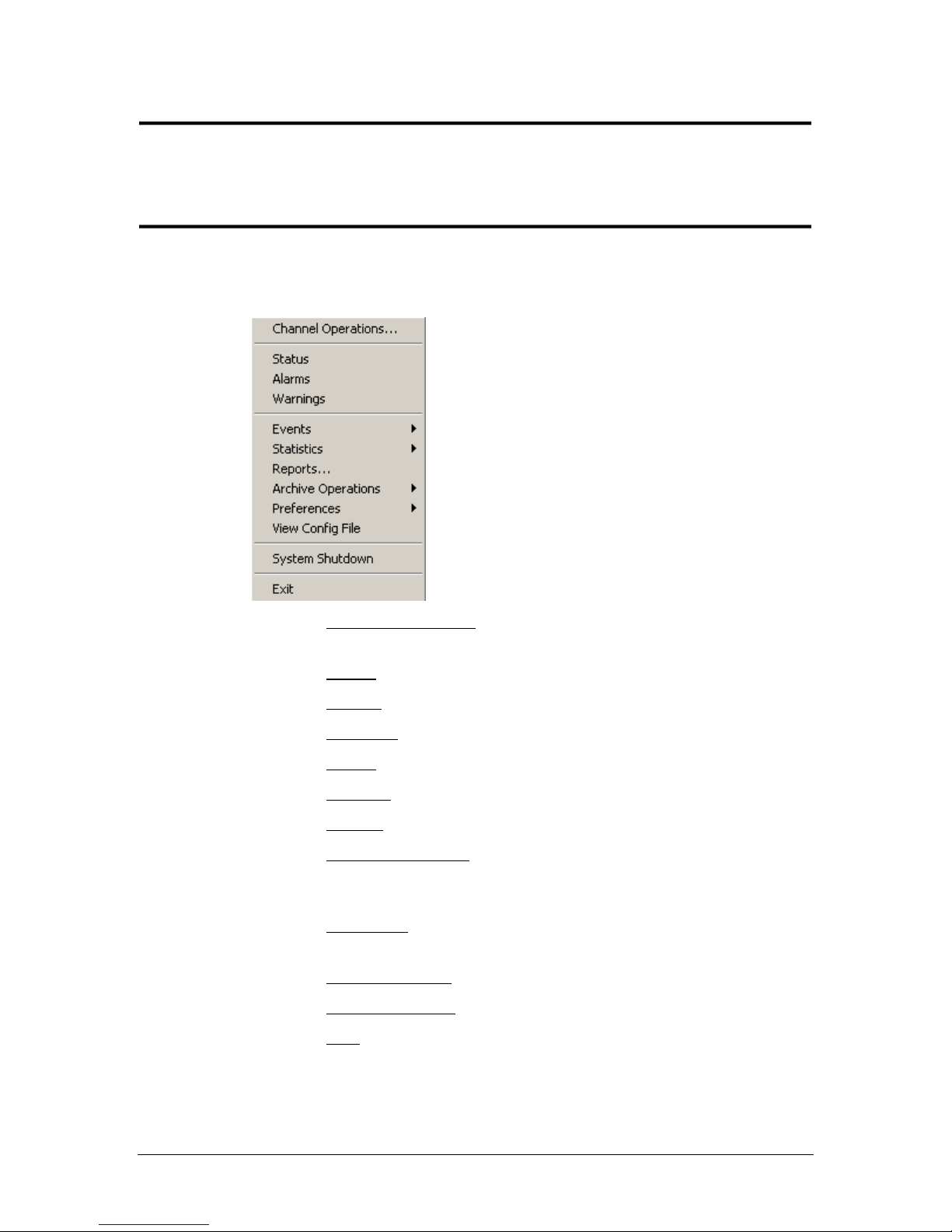
This chapter describes the System Menu. When System is selected from the
menu bar, a pull-down menu is displayed:
Select Channel Operations for functions to monitor and control
channels.
Select Status to display the current system status.
Select Alarms to display alarm notifications.
Select Warnings to display warning notifications.
Select Events for functions to control audit log data.
Select Statistics to enable/disable statistics collection.
Select Reports to display and print reports.
Select Archive Operations for functions to set the purge age of
information in the Message Archive, statistics log files, and event log files
and to purge all logs.
Select Preferences for functions to specify a disk threshold and the
maximum amount of time to wait for a command response.
Select View Config File to display the CP-145 configuration file.
Select System Shutdown to gracefully shut down the entire system.
Select Exit to exit the CP-145 user interface.
/cpe/CP-145/usm/004 (07/14) 3-1
Page 19
ACP-145 Gateway User's Guide
3.1
CHANNEL OPERATIONS
This sub-menu option enables the operator to perform channel-related
operations, including opening and closing a channel, displaying and
modifying channel parameters, and suspending and resuming message output
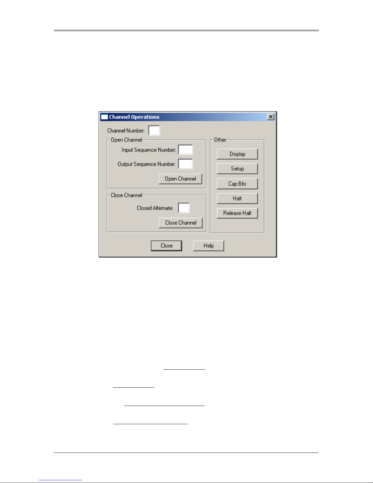
to channels. When Channel Operations is selected from the System Menu
(or the Channels button is selected in the CP-145 Gateway Main Window),
the Channel Operations window is displayed:
Channel Number: Enter a number identifying the CP-145 Gateway I/O
channel to which the operations in this window will be applied. It is not
required to display channel status information.
NOTE: An error message will be displayed if the selected channel number
is out of range or if the specified channel has not been configured with the
CP-145 configuration utility.
Input Sequence Number: This field is not applicable to the CP-145.
Output Sequence Number: This field is not applicable to the CP-145.
Closed Alternate: This field is not applicable to the CP-145
Select the Open Channel button to open a previously closed CP-145
I/O channel. See “Open Channel” below.
Select the Close Channel button to close a CP-145 I/O Channel. See
“Close Channel” below.
Select the Display button to display channel configuration parameters.
See “Display Channel Parameters” below.
Select the Setup button to define channel configuration parameters. See
“Setup Channel Parameters” below.
3-2 /cpe/CP-145/usm/004 (07/14)
Page 20

Select the Cap Bits button to define special channel capabilities. See
3.1.1 Open Channel
3.1.2 Close Channel
3.1.3 Display Channel Parameters
“Cap Bits” below.
Select the Halt button to halt a channel. See “Halt Output to Channel”
below.
Select the Release Halt button to release a channel that was previously
halted. See “Release Channel Halt” below.
Select the Close button to exit this window.
Select the Help button to display CP-145 Gateway Help script about the
Channel Operations window.
The Open Channel button is provided to enable the operator to open a
channel and resume message traffic from/to the channel. When the Open
Channel button is selected in the Channel Operations window, channel
parameters are displayed in a Response window. The Channel Status field
will indicate the new state of the channel (Open). See “Display Channel
Parameters” for a description of the remaining fields in this window. Select
the Close button to exit this window.
Chapter 3. System Menu
The Close Channel button is provided to enable the operator to close a
channel. When the Close Channel button is selected in the Channel
Operations window, channel parameters are displayed in a Response
window. The Channel Status field will indicate the new state of the channel
(Closed). See “Display Channel Parameters” for a description of the
remaining fields in this window. Select the Close button to exit this window.
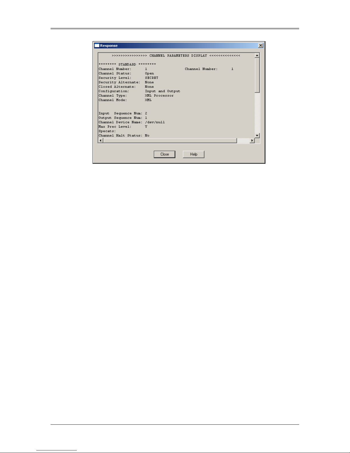
The Display button is provided to enable the operator to display channel
parameters for a selected channel. When the Display button is selected in
the Channel Operations window, channel parameters are displayed in a
Response window:
/cpe/CP-145/usm/004 (07/14) 3-3
Page 21
ACP-145 Gateway User's Guide
Use the vertical scroll bar as necessary to view channel parameters outside
the display space of the window.
**** STANDARD ****
Channel Number: This field indicates the number of the channel that was
selected for display.
Channel Status: This field indicates the current status of the specified
channel: Open, Closed, or Shutdown.
Security Level: This field indicates the security level of the specified
channel: Unclassified, EFTO, Restricted, Confidential, Secret, or Top Secret.
Security Alternate: This field indicates the channel where messages will be
routed in the event of a security violation.
Closed Alternate: This field indicates the channel where messages will be
routed if the specified output channel is closed.
Configuration: This field indicates the direction of the data for the specified
channel (Unused, Output, Input, or Input/Output (for bi-directional)).
Channel Type: This field indicates the configured channel type: X.400,
XML. 128 Network, or 128 Backside
Channel Mode: This field indicates the configured operating mode:
Email: X.400.
XML: custom CP-145 I/O channel.
Mode II ASYNC: Asynchronous RS232 connection. Can be ITA2 or
IA5.
Mode I AID: Synchronous connection via an AUTODIN Interface Unit
(external communications box).
External: for a custom I/O interface.
3-4 /cpe/CP-145/usm/004 (07/14)
Page 22

Chapter 3. System Menu
Input Sequence Num: If the channel mode is configured as Mode II
ASYNC or External and the channel is configured for input or input/output,
this field identifies the sequence number in which to resume message input
when a closed channel is opened.
Output Sequence Num: If the channel mode is configured as Mode II
ASYNC or External and the channel is configured for output or
input/output, this field identifies the sequence number in which to resume
message output when a closed channel is opened.
Channel Device Name: This field indicates the channel’s device name. This
name is configured during system installation by the CP-145 configuration
utility.
Max Prec Level: This field indicates the highest precedence level of
messages that can be received on this channel: Y=Emergency, Z=Flash,
O=Immediate, P=Priority, or R=Routine. The highest precedence level is
“Y”; the lowest precedence level is “R”.
Specats: This field indicates which special categories (A, B, F, L, P, or Y) of
messages are enabled for the channel. The special categories are configured
during system installation by the CP-145(L) configuration utility.
Channel Halt Status: This field indicates whether the channel has been
halted (Yes or No).
Channel Intercept: This field is not applicable to the CP-145.
Max Chan Seq Num: This field identifies the maximum sequence number
that can be assigned to a message on a channel before the number is reset to
1. This number is specified via the Setup button in the Channel Operations
dialog.
CSN Reset Hour: This field identifies the hour (in Greenwich Mean Time)
that the Channel Sequence Number (in the above field) is automatically reset
to 1. This hourly value is specified via the Setup button in the Channel
Operations dialog.
Group Name: This field identifies the name of the group to which the
channel belongs (i.e., provided it has been assigned to a particular group). A
channel can be assigned to a group via Channel Grouping in the
System/Channels sub-menu.
**** MODE SPECIFIC ****
The number and type of mode specific parameters that are displayed depend
on the configured channel mode. For Email mode channels, the remaining
fields are not displayed.
Baud Rate: This field indicates the configured data transfer rate of the
channel: 50, 75, 100, 110, 134, 200, 300, 600, 1200, 1800, 2400, 4800, 9600,
or 19200 bps.
/cpe/CP-145/usm/004 (07/14) 3-5
Page 23

ACP-145 Gateway User's Guide
Character Size: This field indicates the configured number of data bits: 5, 7,
or 8.
Stop Bits: This field indicates the configured number of stop bits per
character: One or Two.
Parity Bit: This field indicates the configured character parity: Even, Odd, or
None.
Parity Check: This field indicates configured parity checking enable status:
On or Off.
Modem Control: This field indicates the configured modem control status:
On or Off.
Handshake Protocol: This field indicates the configured modem flow
control protocol: xon/xoff or None.
Input Designator: This field indicates the sequence of three alphabetic
characters (AAA through ZZZ) that uniquely identify messages originating
from the channel.
Output Designator: This field indicates the sequence of three alphabetic
characters (AAA through ZZZ) that uniquely identify messages destined for
the specified channel.
Input Designator: This field is only included in the channel status display if
the channel mode is External. It indicates the name of the user-supplied
external channel handler executable.
Output Designator: This field is only included in the channel status display
if the channel mode is External. It indicates the name of the user-supplied
external channel handler executable.
**** XML Channel Specific Properties ****
XML Message Input: This field indicates the directory that contains input
XML messages.
XML Attachment Input: This field indicates the directory that contains the
attachment(s) associated with input XML messages.
XML Error Input: This field indicates the directory to place input XML
messages that are erred, e.g., do not conform the CP-145 Gateway DTD.
XML Message Output: This field indicates the directory to place output
XML messages.
XML Attachment Output: This field indicates the directory to place the
attachment(s) associated with output XML messages.
XML Error Output: This field indicates the directory to place output XML
messages that are erred.
3-6 /cpe/CP-145/usm/004 (07/14)
Page 24
>>>> CHANNEL CAPABILITY BITS DISPLAY <<<<
3.1.4 Set up Channel Parameters
3.1.4.1 Channel Setup for Email Channels
The only channel capability bit available for either an XML or X.400 channel
is: No History File Storage. See “Define Channel Capability Bits” later in this
chapter for a description of this capability bit.
Select the Close button to exit this window.
Select the Help button to display CP-145 Gateway Help script about
channel parameters.
The Setup button is provided to define channel configuration parameters.
When the Setup button is selected in the Channel Operations window, the
Channel Setup window is displayed. The format of this window will vary
depending on the configured channel mode, i.e., Email, XML, or MODE I.
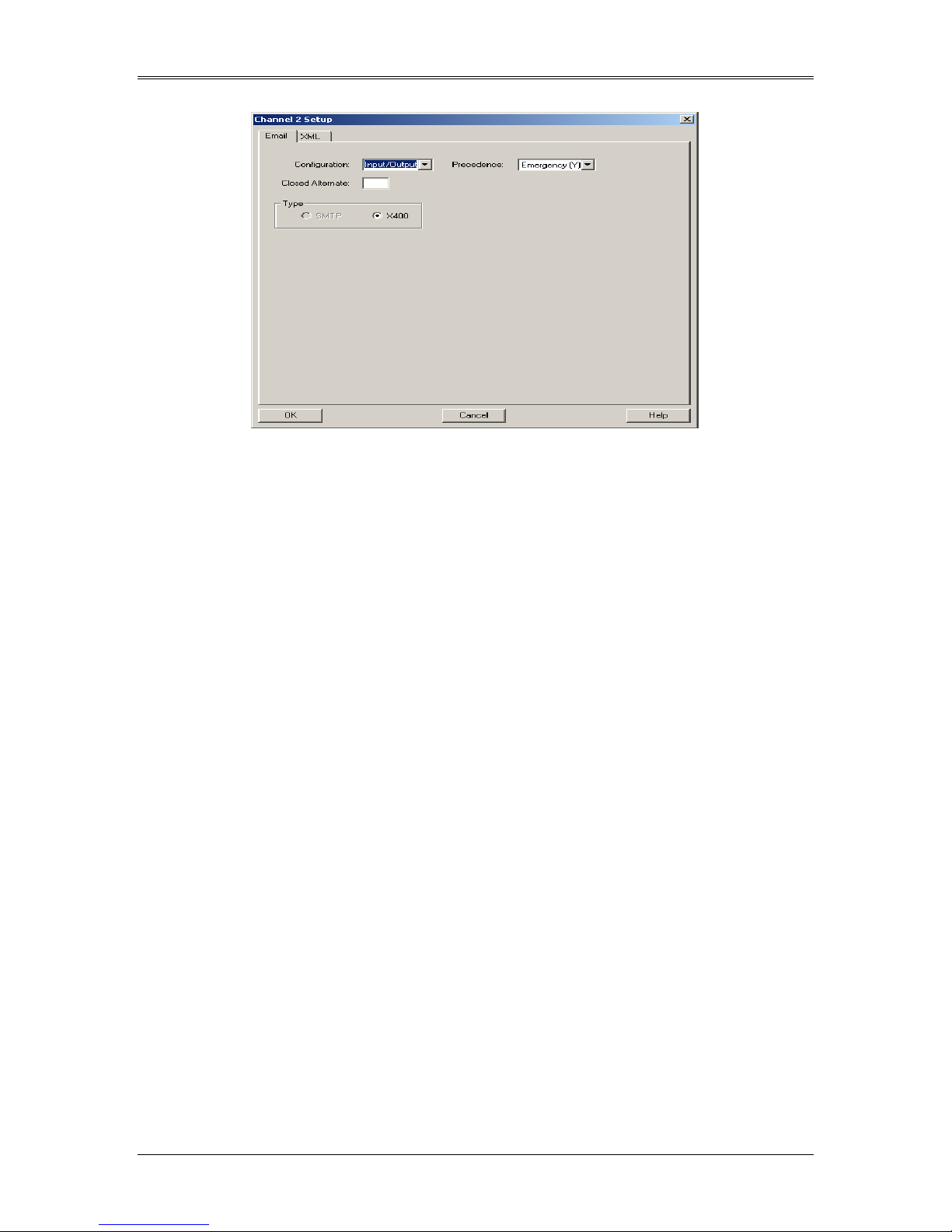
If the channel is configured for Email mode, the following Channel Setup
window is displayed:
Chapter 3. System Menu
/cpe/CP-145/usm/004 (07/14) 3-7
Page 25
ACP-145 Gateway User's Guide
This window is used to define the operational characteristics of CP-145
Gateway I/O channels that are configured as Email. Select one of the tabs
across the top of this window to change the channel mode:
Mode I AID: Select this mode if the channel is a synchronous
connection via an AUTODIN Interface Unit (external communications
box).
Mode II ASYNC: Select this mode if the channel is an asynchronous
RS232 connection. Can be ITA2 or IA5.
External: Select this mode for a custom I/O interface.
Email: Select this mode for X.400.
XML: Select this mode for a custom XML I/O channel.
Configuration: Select the configuration that identifies the direction of the
data for the channel: Unused, Output, Input, or Input/Output (for bidirectional).
Precedence: This field indicates the highest precedence level for the
channel: Y=Emergency, Z=Flash, O=Immediate, P=Priority, or R=Routine.
The highest precedence level is “Y”; the lowest precedence level is “R”.
Messages with a higher precedence level than the level specified here will not
be received on this channel. For example, Immediate, Flash, and Emergency
messages would not be accepted by the channel if this field is set to “P”.
Closed Alternate: This field is not applicable to the CP-145.
Type: Select a channel type: X.400.
Select the OK button to save channel configuration parameters.
Select the Cancel button to exit this window without changing the
channel parameters.
Select the Help button to display CP-145 Gateway Help script about this
window.
3-8 /cpe/CP-145/usm/004 (07/14)
Page 26
Following an OK selection, channel parameters are displayed in a Response
3.1.4.2 Channel Setup for Mode I AID Channels
window. Select the Close button to exit this window.
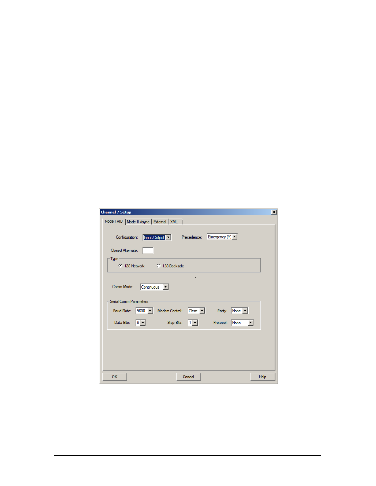
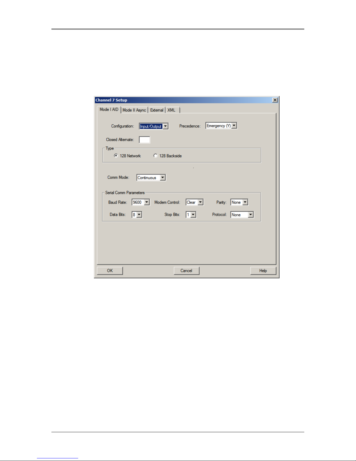
If the channel is configured as Mode I AID, the following Channel Setup
dialog is displayed:
Chapter 3. System Menu
This dialog is used to define the operational characteristics of CP-145 I/O
channels that are configured as Mode I AID. Select one of the tabs across
the top of this dialog to change the channel mode:
Mode I AID: Select this mode if the channel is a synchronous
connection via an AUTODIN Interface Unit (external communications
box).
Mode II ASYNC: Select this mode if the channel is an asynchronous
RS232 connection. Can be ITA2 or IA5.
Email: Select this mode for X.400.
Printer: Select this mode for a connection to a printer.
External: Select this mode for a custom I/O interface.
/cpe/CP-145/usm/004 (07/14) 3-9
Page 27

ACP-145 Gateway User's Guide
3.1.4.3 Channel Setup for Mode II ASYNC Channels
Configuration: Select the configuration that identifies the direction of the
data for the channel: Unused, Output, Input, or Input/Output (for bidirectional).
Precedence: This field indicates the highest precedence level for the
channel: Y=Emergency, Z=Flash, O=Immediate, P=Priority, or R=Routine.
The highest precedence level is “Y”; the lowest precedence level is “R”.
Messages with a higher precedence level than the level specified here will not
be received on this channel. For example, Immediate, Flash, and Emergency
messages would not be accepted by the channel if this field is set to “P”.
Closed Alternate: Specify a channel where traffic will be routed while this
channel is closed.
Type: Select a channel type: 128 Network, 128 Backside, or 128 OTC.
Comm Mode: Select a Mode I communications mode: block or continuous.
Baud Rate: Select the data transfer rate of the channel: 50, 75, 100, 110, 134,
200, 300, 600, 1200, 1800, 2400, 4800, 9600, or 19200.
Modem Control: Select a modem control status: Set or Clear.
Parity: Select character parity: Even, Odd, or None.
Data Bits: Select the number of data bits per character: 5, 7, or 8.
Stop Bits: Select the number of stop bits per character: One or Two.
Protocol: Select XON-XOFF modem flow control or no modem flow
control.
Select the OK button to save channel configuration parameters.
Select the Cancel button to exit this function without changing the
channel parameters.
Select the Help button to display CP-145 Help script about this dialog.
Following an OK selection, channel parameters are displayed in a Response
dialog. Select the Close button to exit this dialog.
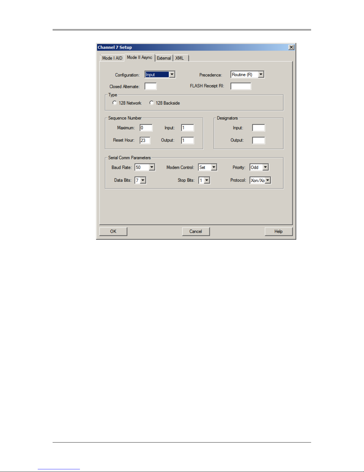
If the channel is configured as Mode II ASYNC, the following Channel
Setup dialog is displayed:
3-10 /cpe/CP-145/usm/004 (07/14)
Page 28
Chapter 3. System Menu
This dialog is used to define the operational characteristics of CP-145 I/O
channels that are configured as Mode II ASYNC. Select one of the tabs
across the top of this dialog to change the channel mode:
Mode I AID: Select this mode if the channel is a synchronous
connection via an AUTODIN Interface Unit (external communications
box).
Mode II ASYNC: Select this mode if the channel is an asynchronous
RS232 connection. Can be ITA2 or IA5.
Email: Select this mode for X.400 or SMTP.
External: Select this mode for a custom I/O interface.
Configuration: Select the configuration that identifies the direction of the
data for the channel: Unused, Output, Input, or Input/Output (for bidirectional).
Precedence: This field indicates the highest precedence level for the
channel: Y=Emergency, Z=Flash, O=Immediate, P=Priority, or R=Routine.
The highest precedence level is “Y”; the lowest precedence level is “R”.
Messages with a higher precedence level than the level specified here will not
be received on this channel. For example, Immediate, Flash, and Emergency
messages would not be accepted by the channel if this field is set to “P”.
/cpe/CP-145/usm/004 (07/14) 3-11
Page 29

ACP-145 Gateway User's Guide
Closed Alternate: Specify a channel where traffic will be routed while this
channel is closed.
FLASH Receipt RI: Specify a DSRI value for FLASH Receipts generated in
response to FLASH messages input to the channel. The value can be up to 8
characters in length, consisting of only alpha/numeric characters.
The FLASH Receipt RI must be defined in the local cache and have a local
channel of the gateway associated with it. See Chapter 5 for information on
how to define routing indicators.
If a value is not placed in this field, then the OSRI of an input FLASH
message will be used as the DSRI in the FLASH Receipt output for the
channel.
Type: Select a channel type: 128 Network, 128 Backside, 128 OTC, 127
Network, or 127 Backside.
Sequence Number/Maximum Number: Each time the CP-145 outputs a
JANAP/ACP-128 or an ACP-127 message it is assigned an output sequence
number. The sequence number is a type of message ID used for tracking
messages in the network. Each JANAP/ACP-128 or ACP-127 message that
the CP-145 receives will contain an input sequence number. The largest
sequence (input/output) number allowed is typically 9999; however, some
systems cannot handle sequence numbers larger than 999. This field specifies
the largest sequence number allowed for the specified channel. When the
maximum number is reached, it will be reset to one.
Sequence Number/Reset Hour: This field can be used to further govern
the maximum sequence number. If the Reset Hour is reached before the
Maximum Number is reached, the sequence number is reset to one.
Sequence Number/Input Number: If the channel is configured for input or
input/output, enter the sequence number in which to resume message input
when the channel is opened.
Sequence Number/Output Number: If the channel mode is configured for
output or input/output, enter the sequence number in which to resume
message output when the channel is opened.
Input Designator: Enter a sequence of three alphabetic characters (AAA
through ZZZ) that uniquely identify messages originating from the channel.
This field is only applicable if the Channel Mode field is set to Mode II
ASYNC or External. This field will be grayed out if the Channel Mode is set
to Mode I AID, Printer, or Email.
Output Designator: Enter a sequence of three alphabetic characters (AAA
through ZZZ) that uniquely identify messages destined for the specified
channel. This field is only applicable if the Channel Mode field is set to
External. This field will be grayed out if the Channel Mode is set to Mode I
AID, Mode II ASYNC, Printer, or Email.
Baud Rate: Select the data transfer rate of the channel: 50, 75, 100, 110, 134,
200, 300, 600, 1200, 1800, 2400, 4800, 9600, or 19200.
3-12 /cpe/CP-145/usm/004 (07/14)
Page 30
Modem Control: Select a modem control status: Set or Clear.
3.1.4.4 Channel Setup for External Channels
Parity: Select Even, Odd, or None.
Data Bits: Select the number of data bits per character: 5, 7, or 8.
Stop Bits: Select the number of stop bits per character: One or Two.
Protocol: Select XON-XOFF modem flow control or no modem flow
control.
Select the OK button to save channel configuration parameters.
Select the Cancel button to exit this dialog without changing the channel
parameters.
Select the Help button to display CP-145 Help script about this dialog.
Following an OK selection, channel parameters are displayed in a Response
dialog. Select the Close button to exit this dialog.
Chapter 3. System Menu
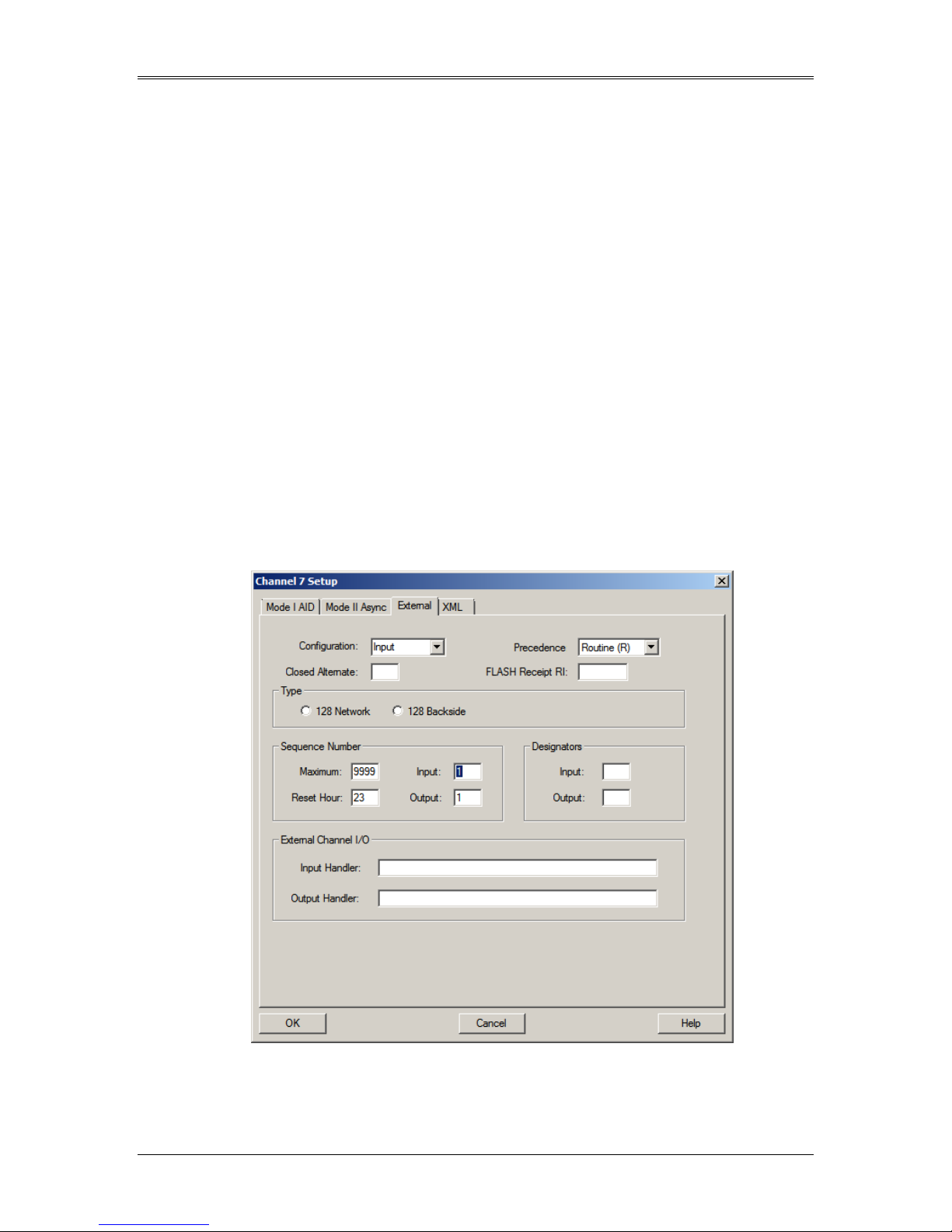
If the channel is configured for External mode, the following Channel Setup
dialog is displayed:
/cpe/CP-145/usm/004 (07/14) 3-13
Page 31

ACP-145 Gateway User's Guide
This dialog is used to define the operational characteristics of CP-145 I/O
channels that are configured as External. Select one of the tabs across the top of
this dialog to change the channel mode:
Mode I AID: Select this mode if the channel is a synchronous
connection via an AUTODIN Interface Unit (external communications box).
Mode II ASYNC: Select this mode if the channel is an asynchronous
RS232 connection. Can be ITA2 or IA5.
External: Select this mode for a custom I/O interface.
Configuration: Select the configuration that identifies the direction of the data
for the channel: Unused, Output, Input, or Input/Output (for bi-directional).
Precedence: This field indicates the highest precedence level for the channel:
Y=Emergency, Z=Flash, O=Immediate, P=Priority, or R=Routine. The highest
precedence level is “Y”; the lowest precedence level is “R”. Messages with a
higher precedence level than the level specified here will not be received on this
channel. For example, Immediate, Flash, and Emergency messages would not be
accepted by the channel if this field is set to “P”.
Closed Alternate: Specify a channel where traffic will be routed while this
channel is closed.
FLASH Receipt RI: Specify a DSRI value for FLASH Receipts generated in
response to FLASH messages input to the channel. The value can be up to 8
characters in length, consisting of only alpha/numeric characters.
The FLASH Receipt RI must be defined in the local cache and have a local
channel of the gateway associated with it. See Chapter 5 for information on how
to define routing indicators.
If a value is not placed in this field, then the OSRI of an input FLASH message
will be used as the DSRI in the FLASH Receipt output for the channel.
Type: Select a channel type: 128 Network or 128 Backside
Sequence Number/Maximum Number: Each time the CP-145 outputs a
JANAP/ACP-128 message it is assigned an output sequence number. The
sequence number is a type of message ID used for tracking messages in the
network. Each JANAP/ACP-128 message that the CP-145 receives will contain
an input sequence number. The largest sequence (input/output) number allowed
is typically 9999; however, some systems cannot handle sequence numbers larger
than 999. This field specifies the largest sequence number allowed for the
specified channel. When the maximum number is reached, it will be reset to one.
Sequence Number/Reset Hour: This field can be used to further govern the
maximum sequence number. If the Reset Hour is reached before the Maximum
Number is reached, the sequence number is reset to one.
Sequence Number/Input Number: If the channel is configured for input or
input/output, enter the sequence number in which to resume message input
when the channel is opened.
3-14 /cpe/CP-145/usm/004 (07/14)
Page 32

Chapter 3. System Menu
3.1.4.5 Channel Setup for XML Channels
Sequence Number/Output Number: If the channel is configured for output or
input/output, enter the sequence number in which to resume message output
when the channel is opened.
Input Designator: Enter a sequence of three alphabetic characters (AAA
through ZZZ) that uniquely identify messages originating from the channel.
Output Designator: Enter a sequence of three alphabetic characters (AAA
through ZZZ) that uniquely identify messages destined for the specified channel.
External Channel I/O - Input Handler/Output Handler: These fields contain
the name of user-supplied channel handler executables and any required
parameters. (When the channel is opened or closed, the executables specified
here will be started or stopped.) This capability allows you to develop your own
custom channel handlers that will be used by the CP-145 to input/output
messages. When using the External channel handlers, i.e., ich_ext.exe (Input
Handler) and och_ext.exe (Output Handler), delivered along with the CP-145
software and placed in the C:\cpe\csci\mfg\bin\IO\ folder at installation time,
enter the information as follows when configuring, for example, Channel 2 as an
External channel:
ich_ext.exe 10 2 2 C:\tmp\
och_ext.exe 10 2 2 C:\tmp\
The parameters (to the right of the executable names) are used when the
associated processes are started and are defined as follows: The first parameter
represents the total number of channels supported by the CP-145 (e.g., 10
channels); the second and third parameters represent the CP-145 channel
number that is being configured as External (e.g., Channel 2); and the last
parameter represents the folder (full path required) where the input and output
text files will be read from and written to, respectively (e.g., C:\tmp).
Select the OK button to save channel configuration parameters.
Select the Cancel button to exit this dialog without changing the channel
parameters.
Select the Help button to display CP-145 Help script about this dialog.
Following an OK selection, channel parameters are displayed in a Response
dialog. Select the Close button to exit this dialog.
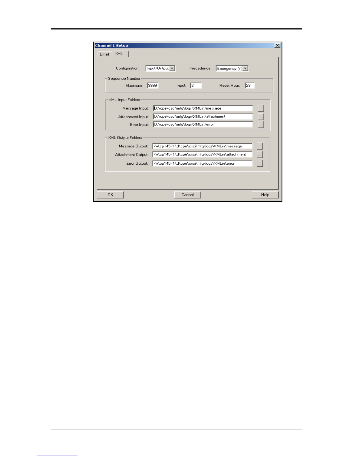
If the channel is configured for XML mode, the following Channel Setup
window is displayed:
/cpe/CP-145/usm/004 (07/14) 3-15
Page 33
ACP-145 Gateway User's Guide
This window is used to define the operational characteristics of CP-145
Gateway channels that are configured in XML mode. Select one of the tabs
across the top of this window to change the channel mode:
Email: Select this mode for X.400.
XML: Select this mode for a custom XML I/O channel.
Configuration: Select the configuration that identifies the direction of the
data for the channel: Unused, Output, Input, or Input/Output (for bidirectional).
Precedence: This field indicates the highest precedence level for the
channel: Y=Emergency, Z=Flash, O=Immediate, P=Priority, or R=Routine.
The highest precedence level is “Y”; the lowest precedence level is “R”.
Messages with a higher precedence level than the level specified here will not
be received on this channel. For example, Immediate, Flash, and Emergency
messages would not be accepted by the channel if this field is set to “P”.
Sequence Number/Maximum Number: This field is not applicable to the
CP-145. Accept the default value.
Sequence Number/Input Number: This field is not applicable to the CP-
145. Accept the default value.
Sequence Number/Reset Hour:
Accept the default value.
XML Input Folders – Message Input: This field indicates the directory that
contains input XML messages. The drive and path of the desired directory
3-16 /cpe/CP-145/usm/004 (07/14)
This field is not applicable to the CP-145.
Page 34

Chapter 3. System Menu
3.1.5 Define Channel Capability Bits
can be manually entered or the Browse button (…) can be used to select the
directory.
XML Input Folders – Attachment Input: This field indicates the directory
that contains the attachment(s) associated with input XML messages. The
drive and path of the desired directory can be manually entered or the
Browse button (…) can be used to select the directory.
XML Input Folders – Error Input:
This field indicates the directory to place
input XML messages that are erred, e.g., do not conform the CP-145
Gateway DTD. The drive and path of the desired directory can be manually
entered or the Browse button (…) can be used to select the directory.
XML Output Folders – Message Output: This field indicates the directory
to place output XML messages. The drive and path of the desired directory
can be manually entered or the Browse button (…) can be used to select the
directory.
XML Output Folders – Attachment Output: This field indicates the
directory to place the attachment(s) associated with output XML messages.
The drive and path of the desired directory can be manually entered or the
Browse button (…) can be used to select the directory.
XML Output Folders – Error Output:
This field indicates the directory to
place output XML messages that are erred. The drive and path of the
desired directory can be manually entered or the Browse button (…) can be
used to select the directory.
Select the OK button to save channel configuration parameters.
Select the Cancel button to exit this window without changing the
channel parameters.
Select the Help button to display CP-145 Gateway Help script about this
window.
Following an OK selection, channel parameters are displayed in a Response
window. Select the Close button to exit this window.
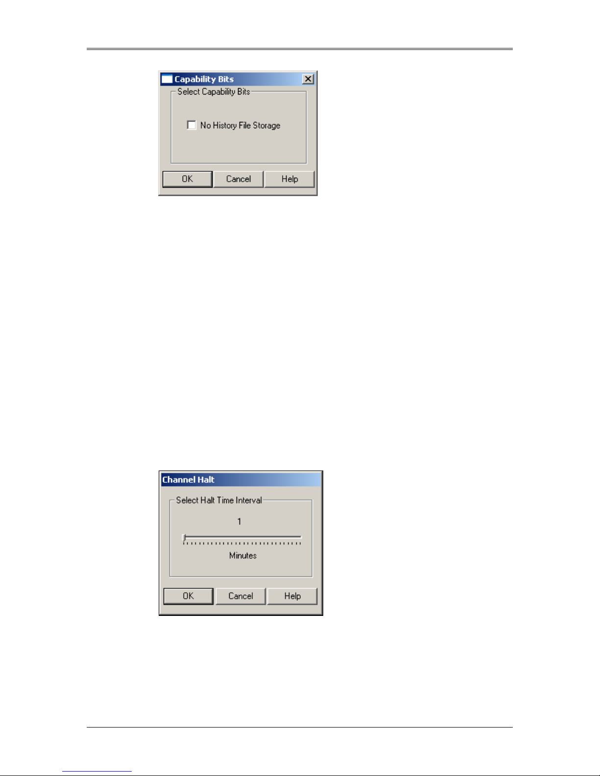
The Cap Bits button is provided to define additional channel capabilities.
When the Cap Bits button is selected in the Channel Operations window,
the Capability Bits window is displayed:
/cpe/CP-145/usm/004 (07/14) 3-17
Page 35
ACP-145 Gateway User's Guide
3.1.6 Halt Output to a Channel
For the CP-145 Gateway, the following capability bit is available:
No Message Archive: This capability bit selects No History File Storage. By
default, all messages received are stored in the Message Archive. If this bit is
selected, any messages received on this channel will not be stored in the
Message Archive.
Select the OK button to continue.
Select the Cancel button to exit this window without changing channel
parameters.
Select the Help button to display CP-145 Gateway Help script about this
window.
Following an OK selection, channel parameters are displayed in a Response
window. Select the Close button to exit.
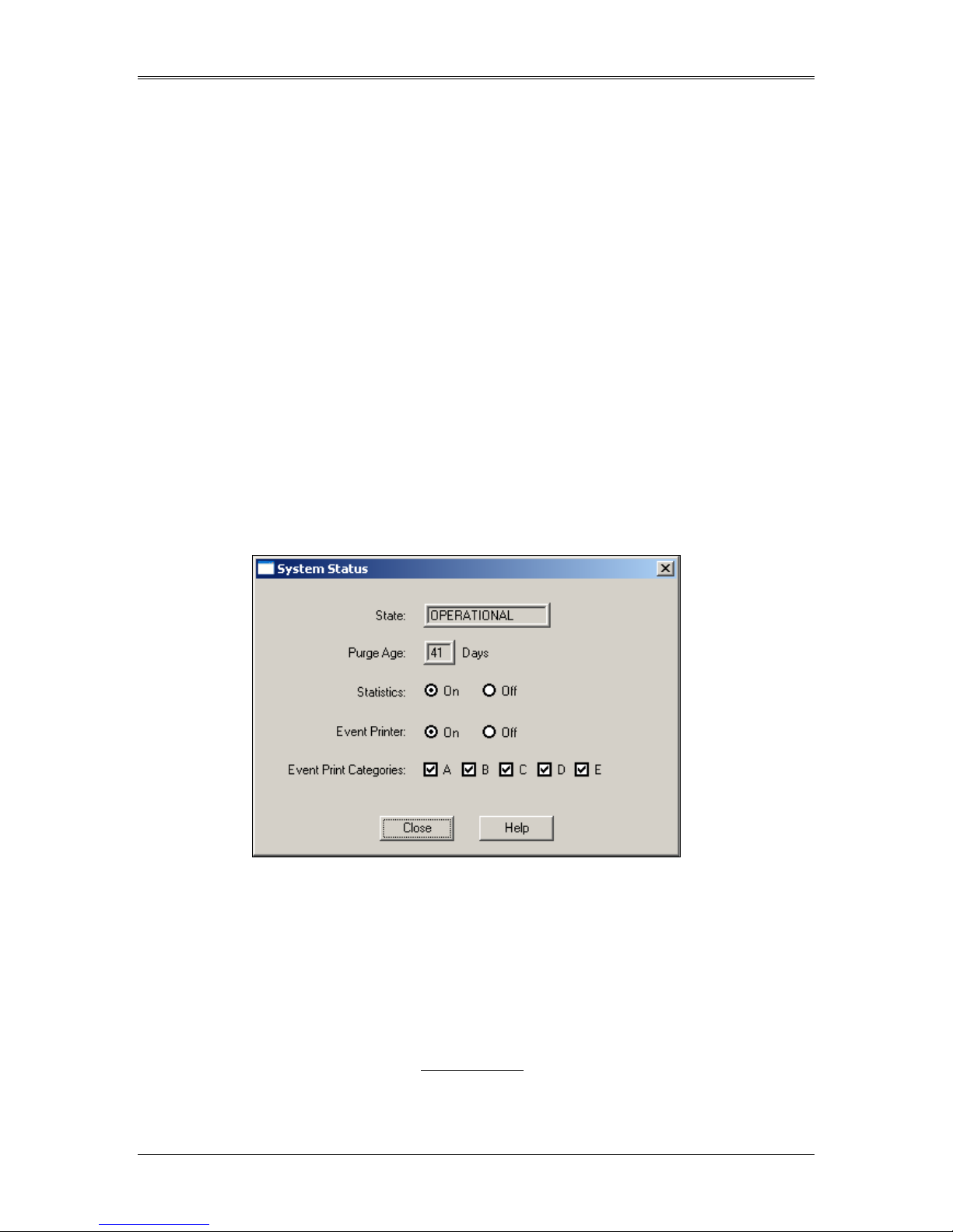
The Halt button is provided to enable the operator to temporarily suspend
message output to a channel. When the Halt button is selected in the
Channel Operations window, the Channel Halt window is displayed:
Use the slider bar to select a time in minutes indicating the amount of time
that the channel can remain on halt before an alarm message is sent to the
user interface as a reminder that the channel is halted.
Select the OK button to continue.
Select the Cancel button to exit this window.
3-18 /cpe/CP-145/usm/004 (07/14)
Page 36
Select the Help button to display CP-145 Gateway Help script about this
3.1.7 Release Channel Halt
3.2
STATUS
window.
Following an OK selection, channel parameters are displayed in a Response
window. The Channel Halt Status field will be set to Yes. See “Display
Channel Parameters” above for a description of the remaining fields in this
window. Select the Close button to exit this window.
The Release Halt button is provided to enable the operator to resume
output to a channel. When the Release Halt button is selected in the
Channel Operations window, channel parameters are displayed in a
Response window. The Channel Halt Status field will be set to No. See
“Display Channel Parameters” above for a description of the remaining
fields in this window. Select the Close button to exit this window.
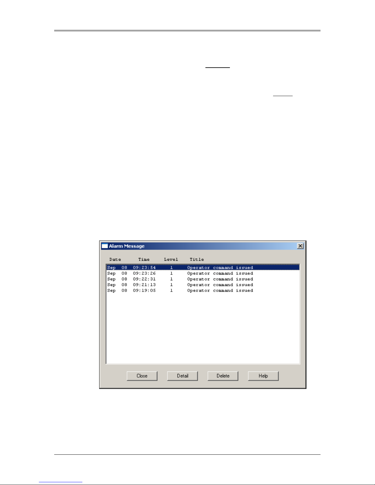
This sub-menu option enables the operator to obtain system status
information. When Status is selected from the System Menu, the System
Status window is displayed:
Chapter 3. System Menu
The status information is continuously updated as long as the system status
window is displayed. The following paragraphs describe the fields in the
System Status window.
State: This field identifies the operational state of the system: Operational or
Initialize. The system must be in the “Operational” state in order for message
processing to occur.
Purge Age: This field identifies the maximum age of messages in the
Message Archive and the age (in days) at which records are purged from the
Message Archive. See “Set Purge Age” below for more information.
/cpe/CP-145/usm/004 (07/14) 3-19
Page 37
ACP-145 Gateway User's Guide
3.3
ALARMS
Statistics: This field identifies the state (On or Off) of hourly statistics
gathering. Statistics collection is enabled/disabled by selecting the Statistics
option from the System Menu. See “Statistics” below for more information.
Event Printer: This field identifies the state (On or Off) and category status
of the event log printer. Event log printing is enabled/disabled by selecting
the Printer option from the System/Events sub-menu. See “Printer” below
for more information.
Event Print Categories: This field identifies the event categories that are
selected for output to the printer.
Select the Close button to exit this window.
Select the Help button to display a CP-145 Help script about this
window.
This sub-menu option enables the operator to display alarms queued to the
Alarms field in the CP-145 Main Window. (Alarm messages are operator
notifications of potentially serious conditions that have occurred within the
CP-145. Please refer to “Event Profile” later in this chapter for a description
of how to tailor events.) When Alarms is selected from the System Menu (or
the Alarms button is selected in the CP-145 Gateway Main Window), the
Alarm Message window is displayed:
Date: This indicates the operating system date that the alarm message was
generated.
Time: This indicates the operating system time that the alarm message was
generated.
3-20 /cpe/CP-145/usm/004 (07/14)
Page 38
3.4
WARNINGS
Chapter 3. System Menu
Level: This indicates the severity level of the alarm message.
Title: This indicates the nature of the alarm message.
Select the Detail button to display additional event-related information
(e.g., event log number) associated with a highlighted alarm message.
(This can also be accomplished by double-clicking the alarm message.)
The resulting information is displayed in the form of an Information
window. Select the OK button to exit.
Select the Delete button to delete a highlighted alarm message.
Select the Close button to exit.
Select the Help button to display CP-145 Gateway Help script about this
window.
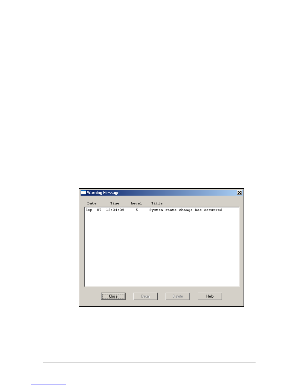
This sub-menu option enables the operator to display warnings queued to
the Warnings field in the CP-145 Main Window. (Warning messages are
operator notifications of less serious conditions that have occurred within the
CP-145. Please refer to “Event Profile” later in this chapter for a description
of how to tailor events.) When Warnings is selected from the System Menu
(or the Warnings button is selected in the CP-145 Gateway Main Window),
the Warning Message window is displayed:
Date: This indicates the operating system date that the warning message was
generated.
Time: This indicates the operating system time that the warning message was
generated.
Level: This indicates the severity level of the warning message.
/cpe/CP-145/usm/004 (07/14) 3-21
Page 39
ACP-145 Gateway User's Guide
3.5
EVENTS
3.5.1 Event Profile
Title: This indicates the nature of the warning message.
Select the Detail button to display additional event-related information
(e.g., event log number) associated with a highlighted warning message.
(This can also be accomplished by double-clicking the warning message.)
The resulting information is displayed in the form of an Information
window. Select the OK button to exit.
Select the Delete button to delete a highlighted warning message.
Select the Close button to exit.
Select the Help button to display CP-145 Gateway Help script about this
window.
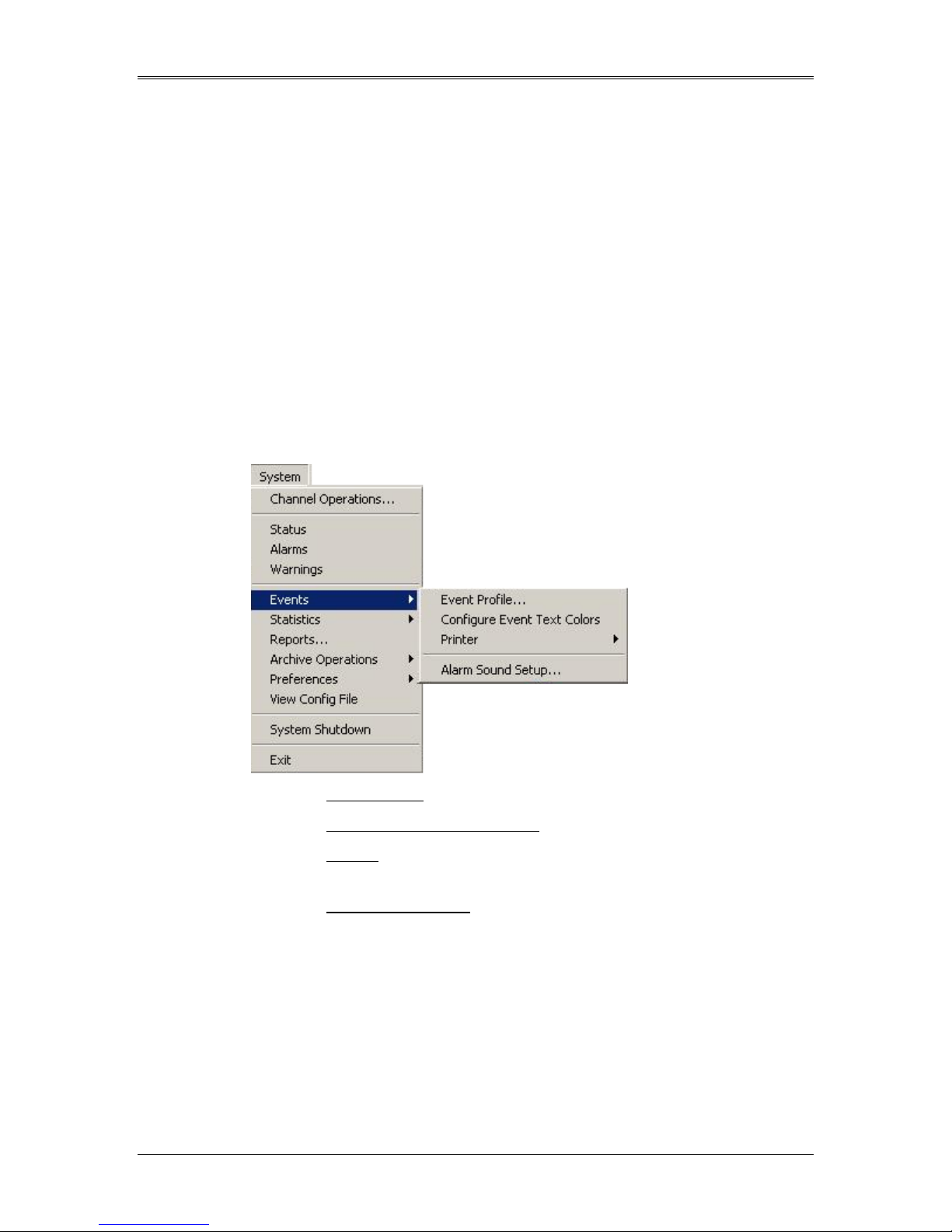
When Events is selected from the System Menu, the Events sub-menu is
displayed:
Select Event Profile to display the Events window.
Select Configure Event Text Colors to configure the event text colors.
Select Printer to select categories of events to print and to enable/disable
event log printing.
Select Alarm Sound Setup to assign audible alarms (or sounds) to be
played when alarms or warnings occur.
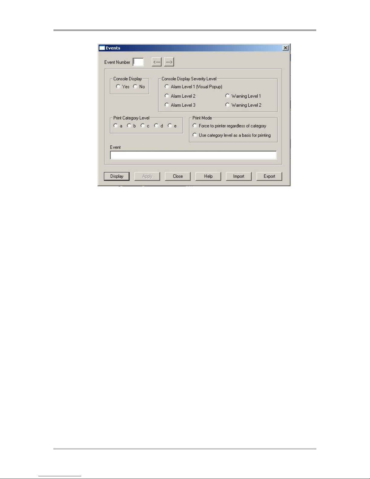
This sub-menu option enables the operator to modify the parameters
associated with an event. When Event Profile is selected from the
System/Events sub-menu, the Events window is displayed:
3-22 /cpe/CP-145/usm/004 (07/14)
Page 40
Chapter 3. System Menu
This window is used to enable/disable the display or printing of event
messages, to define the severity level of an event message, to group messages
into event categories for printing or not printing, to define event message
text, to import a previously set of saved event messages and to export the
current set of event messages.
Event Number: Enter the number of the event to be modified. See
Appendix A for a complete list of events. Select the Display button to
display the selected event in the Events window.
Console Display: Select the “Yes” or “No” radio button to identify whether
or not this event message will be displayed on the operator console (i.e., user
interface).
Console Display Severity Level: Select a severity level (Alarm Level 1,
Alarm Level 2, Alarm Level 3, Warning Level 1, or Warning Level 2, with
Alarm Level 1 being the highest and Warning Level 2 being the lowest). See
the Alarms and/or Warnings sub-menu options above for the procedures to
view Alarm/Warning Messages. When an Alarm Level 1 condition is
detected, a dialog box would display to inform the operator.
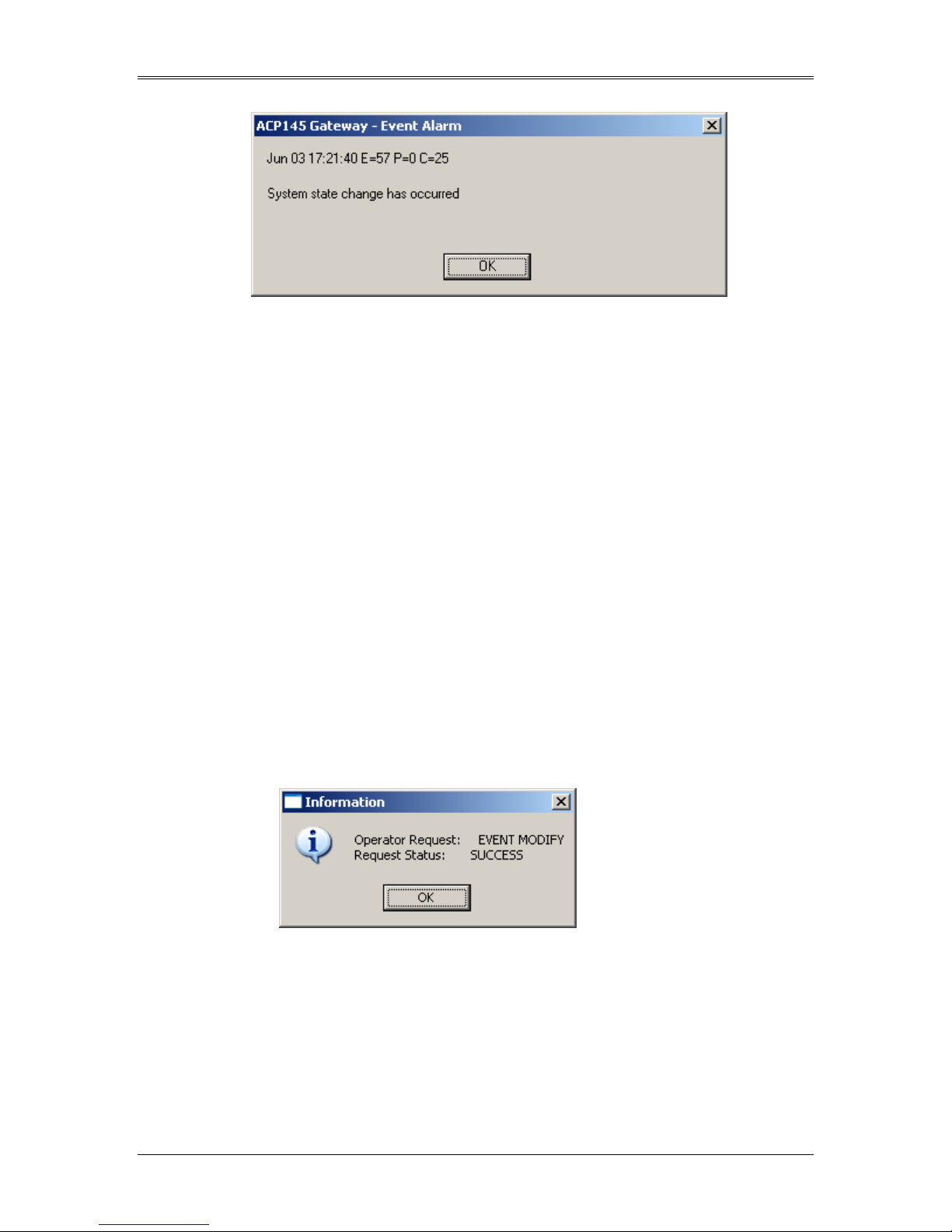
If an Event is set to a Severity Level of Alarm Level 1 (Visual Popup) then a
popup window will be displayed when the Event Message is output. A
typical popup window will be displayed as seen below:
/cpe/CP-145/usm/004 (07/14) 3-23
Page 41
ACP-145 Gateway User's Guide
The popup window can be closed by selecting the OK button or the close
window “X” button in the upper right corner.
To prevent the display of multiple popup windows for a single Event, a
popup for a particular Event will only be displayed, at most, once per hour.
The hour begins with first occurrence of the Event.
Print Category Level: Select a print category level (a-e). Event categories are
used to group similar events and to enable/disable printing of event groups.
For example, you can group all routine events into category “e” and disable
printing group “e” events.
Print Mode: Select the Force to printer regardless of category option to
force the system to print the event regardless of the assigned printer
category. Select the Use category as basis for printing option to enable or
disable the printing based on the assigned print category level. The Setup
option in the System/Events/Printer sub-menu can be used to
enable/disable printing of event messages based on the category grouping.
Event Text: Enter the descriptive text to be associated with this event.
Select the Display button to display the specified event.
Select the Apply button to save the modified event parameters.
Following an Apply selection, an Information window is displayed
indicating the results of the request: SUCCESS or FAIL
Select the OK button to close the window.
Select the Close button to exit this window without changing the event
parameters.
Select the Help button to display an CP-145 Help script about this
window
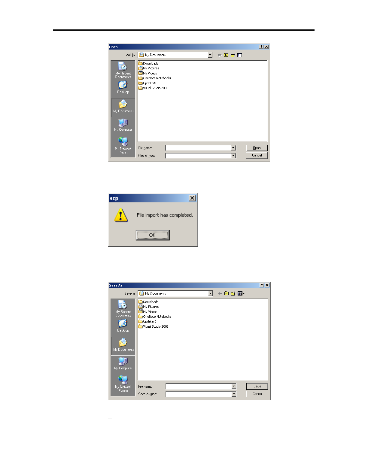
Select the Import button to import a previously exported set of event
messages. When the button is selected the Open window is displayed:
3-24 /cpe/CP-145/usm/004 (07/14)
Page 42
Chapter 3. System Menu
Browse to the folder that contains the file to be used for import.
Highlight the file and select the Open button to import the file. When
the import is complete the SCP window is displayed:
Select the OK button to close the window.
Select the Export button to export the current set of event messages.
When the button is selected the Save As window is displayed:
Browse to the required folder and enter the export filename in the File
name field. Select the Save button to export the file. When the export
is complete the SCP window is displayed:
/cpe/CP-145/usm/004 (07/14) 3-25
Page 43
ACP-145 Gateway User's Guide
3.5.2 Configure Event Text Colors
Select the OK button to close the window.
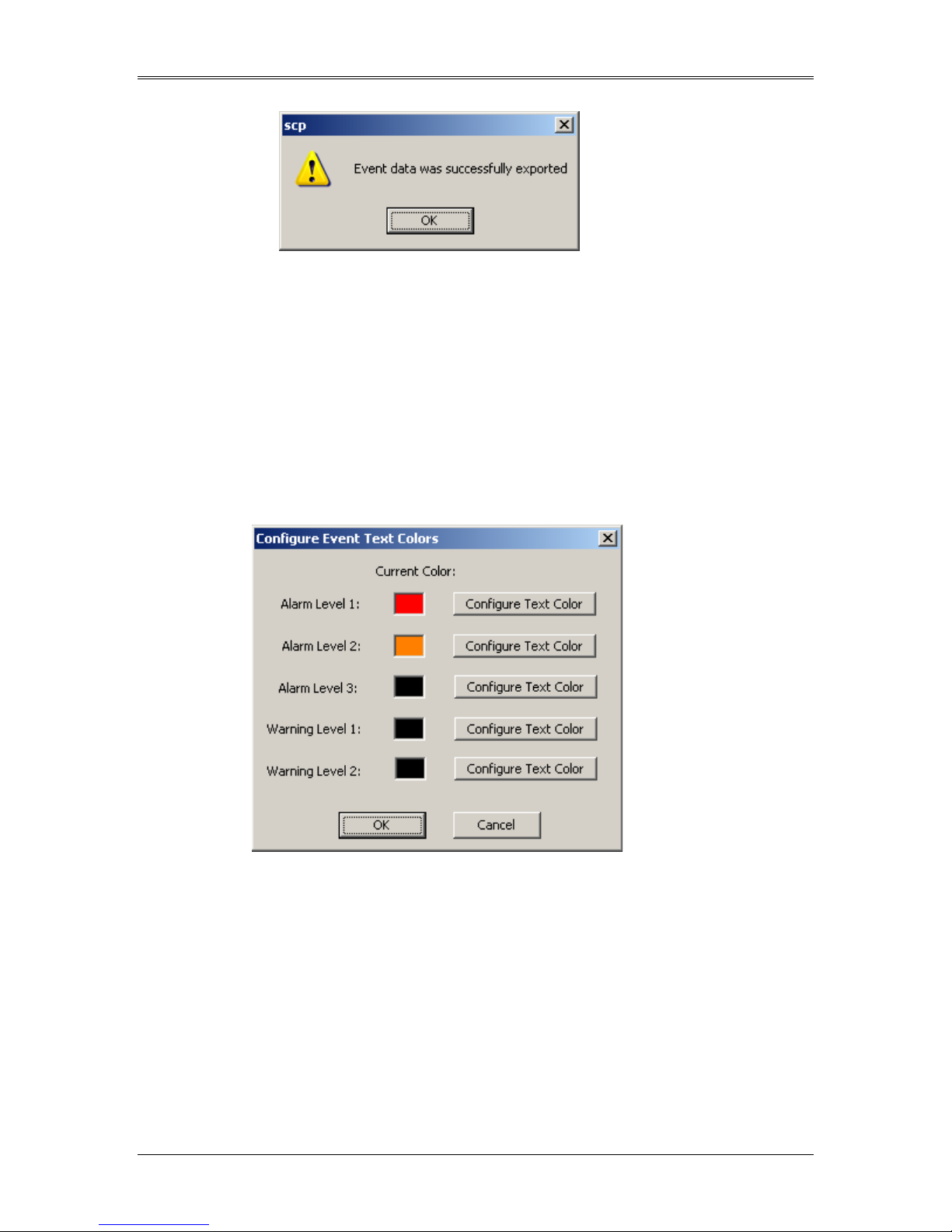
This sub-menu option enables the operator to change the color of the event
text for the Alarm and Warning messages. When Configure Event Text Colors is
selected from the System/Events sub-menu, the Configure Event Text
Colors window is displayed. This window allows the operator to individually
assign a color to the event text message for each Alarm and Warning level.
NOTE: Configuring the color of event text does not apply to the
coloring of the same event text that is displayed in reports. The coloring of
the event messages is only displayed on the SCP or main CP-145 screen.
Select the OK button to accept all changes and close the Configure
Event Text Colors window.
Select the Cancel button to exit.
Select a Configure Text Color button to assign a color to a particular
Alarm or Warning level and the Color window is displayed:
3-26 /cpe/CP-145/usm/004 (07/14)
.
Page 44
Chapter 3. System Menu
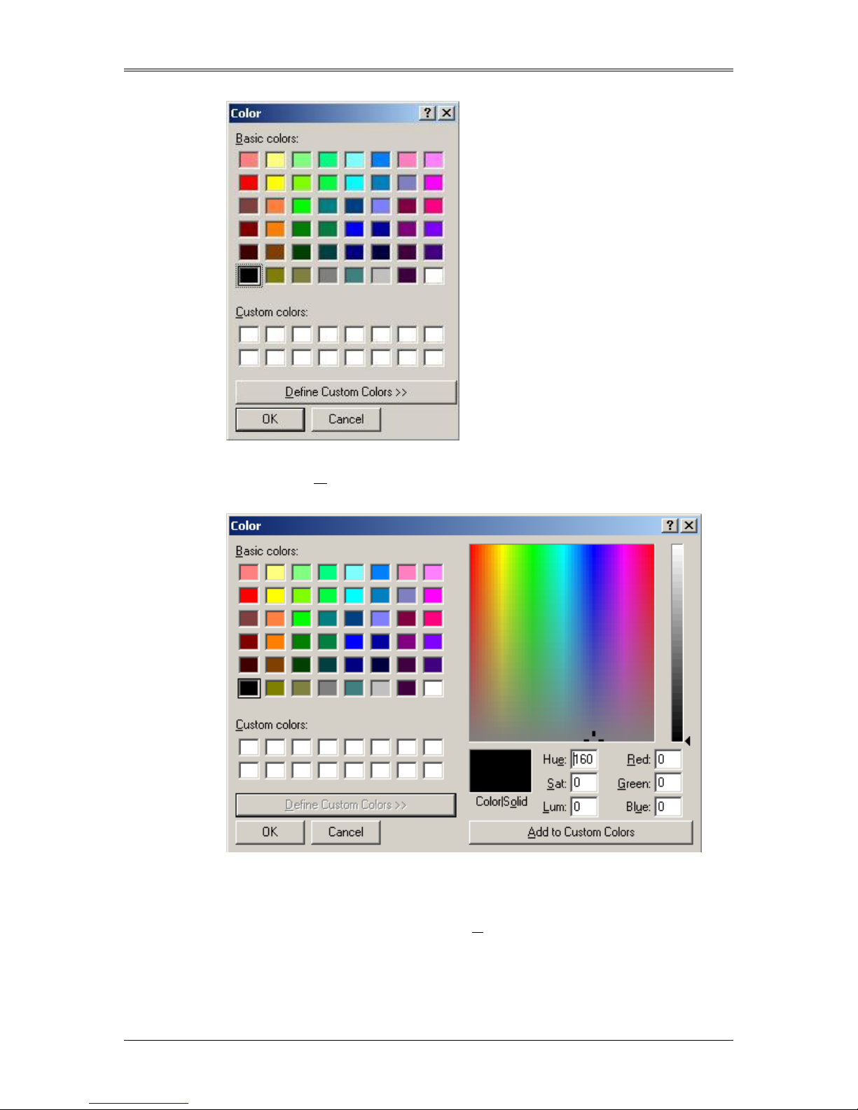
The Color window displays an array of Basic colors to choose from.
Selecting the Define Custom Colors
>> button displays an expanded color
palette view:
The full view of the Color palette provides the operator the choice to select a
color from the Basic colors palette or to select from a Custom colors
palette. The Custom colors palette can be populated by selecting or
customizing a color and selecting the Add to Custom Colors button.
Basic colors: This palette consists of a fixed array of color selections. A
color from this panel can be selected and assigned to a particular Alarm or
Warning level.
/cpe/CP-145/usm/004 (07/14) 3-27
Page 45
ACP-145 Gateway User's Guide
Custom colors: This palette is populated by selecting or customizing a color
on the palette and then selecting the Add to Custom Colors button.
Hue: The property of colors by which they can be perceived as ranging from
red through yellow, green, and blue. The range of values is between 0 and
239.
Sat: Color saturation refers to the intensity and sharpness of a color. The
range of values is between 0 and 240.
The luminosity of a color refers to how bright the color is. The range
Lum:
of values is between 0 and 240.
Red: A larger value in the field produces a more red color.
Green: A larger value in the field produces a more green color.
Blue: A larger value in the field produces a more blue color.
Select the Define Custom Colors button to expand the view of the
color palette.
Select the Add to Custom Colors button to add a color to the Custom
colors palette.
Select the OK button to accept all changes and close the Color window.
Select the Cancel button to exit.
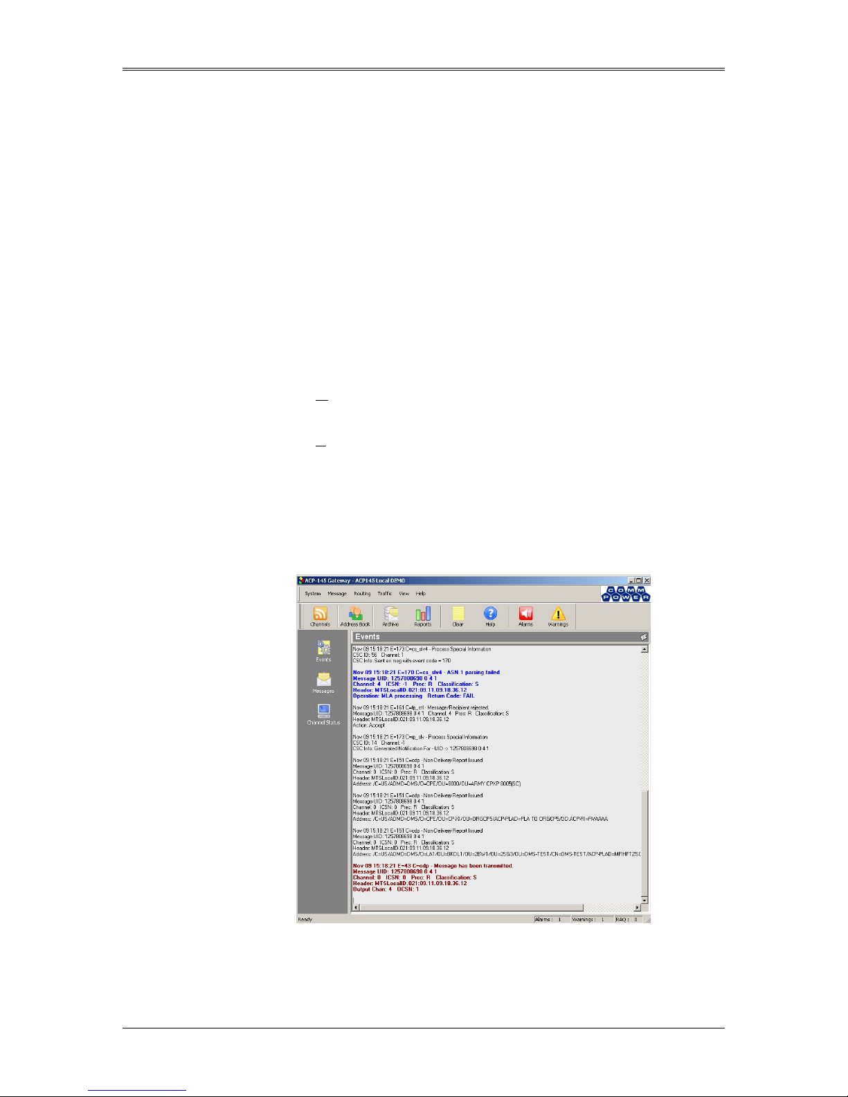
See below for an example of colored event text displayed on the CP-145 user
interface:
3-28 /cpe/CP-145/usm/004 (07/14)
Page 46
3.5.3 Printer
3.5.3.1 Printer Setup
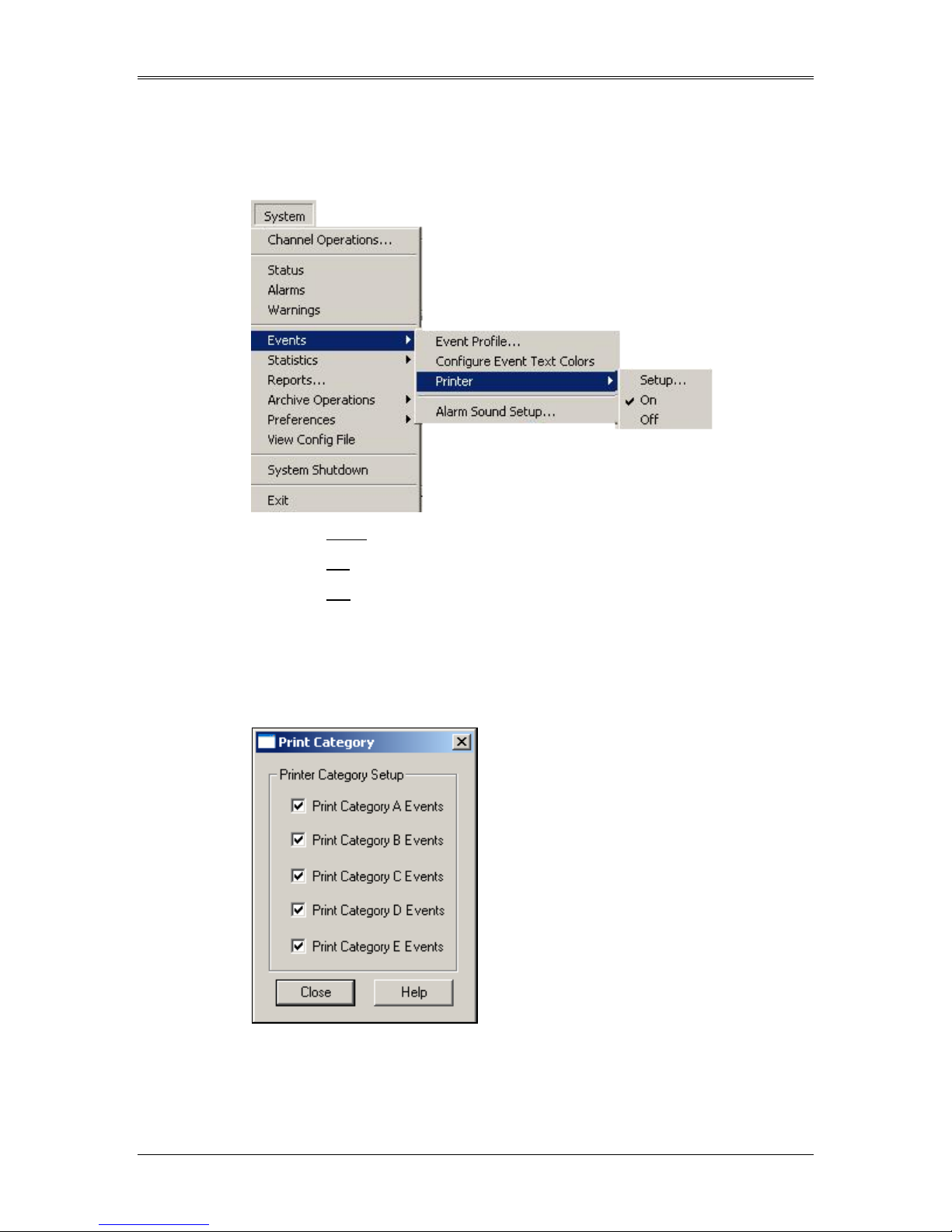
When Printer is selected from the Events sub-menu, the Printer sub-menu is
displayed:
Select Setup to activate/deactivate event category printing.
Chapter 3. System Menu
Select On to enable event log printing.
Select Off to disable log printing.
This sub-menu option enables the operator to define the categories of events
to print. When Setup is selected from the Events/Printer sub-menu, the
Print Category window is displayed:
This window is used to select individual categories of event messages that
should be directed to the event log printer. Event messages can be grouped
into categories using the Event Profile option in the System/Events submenu. Select the category of event messages that should be directed to the
/cpe/CP-145/usm/004 (07/14) 3-29
Page 47
ACP-145 Gateway User's Guide
3.5.3.2 Printer On/Off
3.5.4 Alarm Sound Setup
printer. When a category is selected, an Information window displays the
status of the request. Select the OK button to close the Information
window.
Select the Close button to exit this window.
Select the Help button to display a CP-145 Help script about this
window.
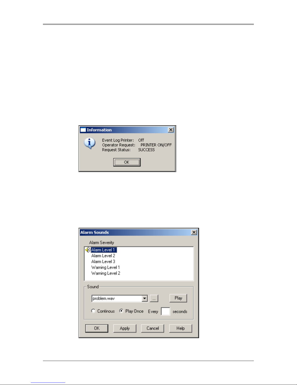
This sub-menu option allows the operator to enable or disable printing.
When On or Off is selected from the Events/Printer sub-menu, an
Information window is displayed indicating the results of the request:
SUCCESS or FAIL.
Select the OK button to exit.
This sub-menu option enables the operator to assign audible alarms (or
sounds) to be played when alarms or warnings occur. When Alarm Sound
Setup is selected from the System/Events sub-menu, the Alarm Sounds
window is displayed:
3-30 /cpe/CP-145/usm/004 (07/14)
Page 48
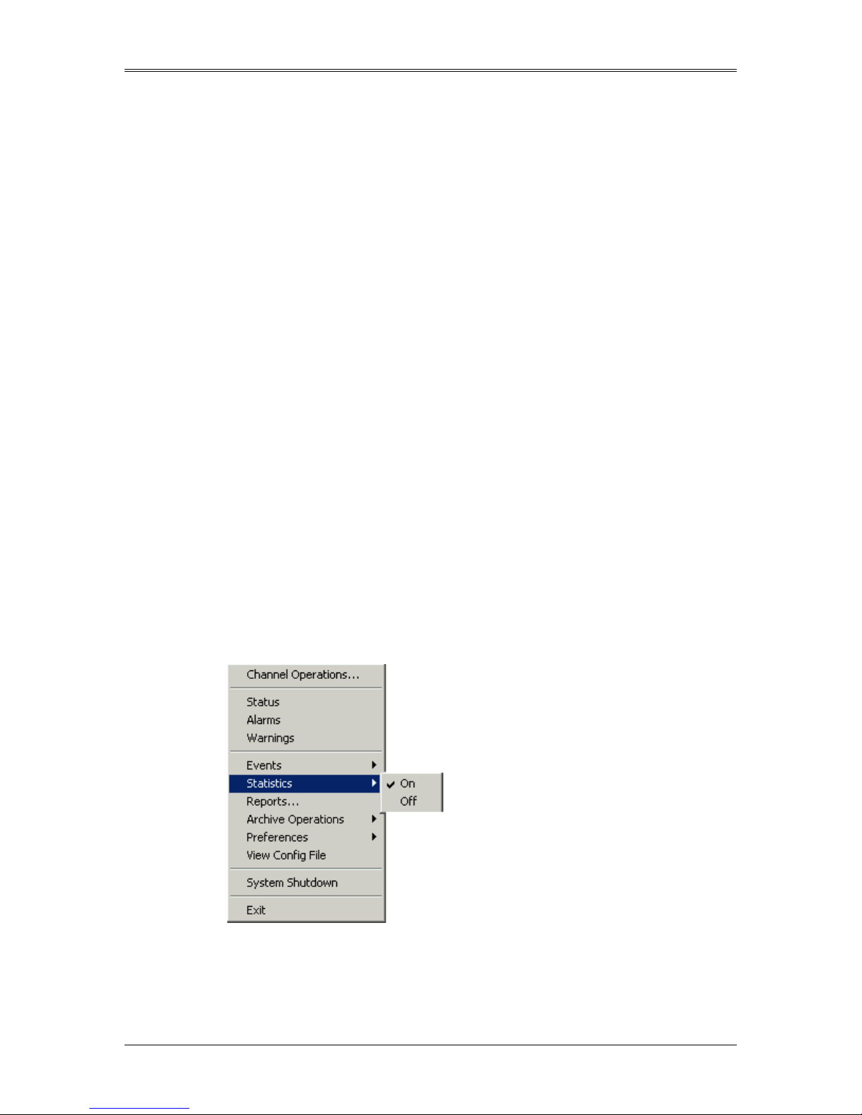
Chapter 3. System Menu
3.6
STATISTICS
Alarm Severity: Select the alarm/warning severity level (i.e., Alarm Level 1,
Alarm Level 2, Alarm Level 3, Warning Level 1, or Warning Level 2) with
which to associate a sound. (These severity levels are assigned to event
messages via the Event Profile sub-menu. If necessary, refer to “Event
Profile” above.)
Sound: Select the desired sound (in .wav format) via the drop-down menu. If
necessary, select the browse button to locate and select a sound file residing
elsewhere (i.e., in a directory other than the default C:\cpe\sounds directory).
Select the Play button to play a selected sound.
Continuous, Play Once, Every_____Seconds: Select the desired audible
alarm frequency or rate of occurrence. If the operator wants the audible
alarm to be played in accordance with a specified time sequence in seconds,
enter the number of seconds in the Every_____Seconds field.
Select the OK button to save the assigned audible alarm and close the
Alarm Sounds window.
Select the Apply button to apply the assigned audible alarm and retain
the Alarm Sounds window (for the purpose of assigning additional
audible alarms).
Select the Cancel button to exit this window without assigning or
changing audible alarms.
Select the Help button to display a CP-145 Help script about this
window.
When Statistics is selected from the System Menu, the Statistics sub-menu is
displayed:
Select On to enable the collection of data for statistics reporting.
Select Off to disable statistics data collection.
/cpe/CP-145/usm/004 (07/14) 3-31
Page 49
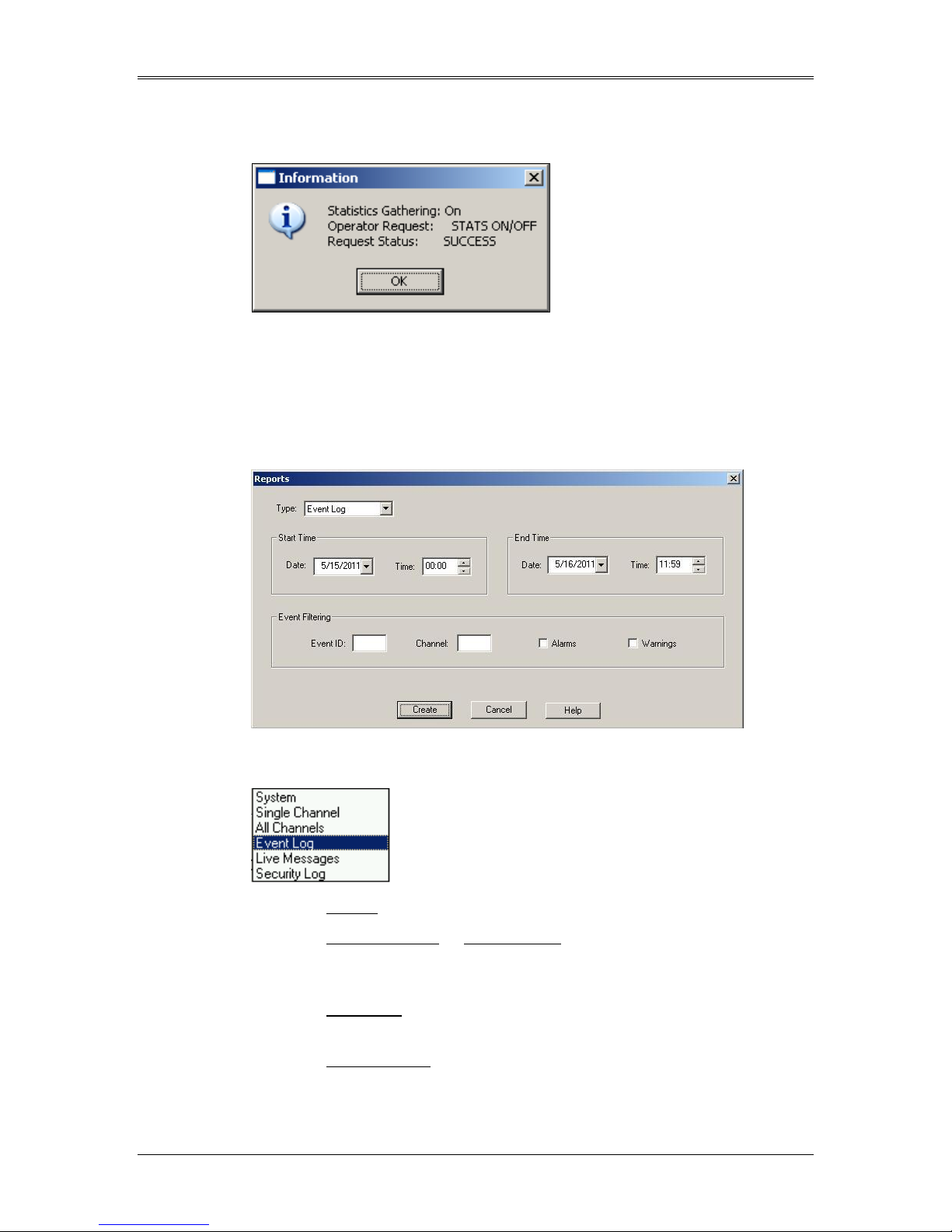
ACP-145 Gateway User's Guide
3.7
REPORTS
An Information window is displayed indicating the results of the request:
SUCCESS or FAIL.
Select the OK button to exit.
This sub-menu option enables the operator to display and print various
reports. When Reports is selected from the System Menu, the Reports
window is displayed:
Report Type: Select this field to display a drop-down list of available report
types:
Select System to display the System Activity Report.
Select Single Channel or All Channels to display a Channel Activity
Report for a single channel or all CP-145 Gateway I/O channels,
respectively.
Select Event Log to display a list of events in the form of an Event Log
Report.
Select Live Messages to display information about each message that is
within the confines of the CP-145 Gateway. These are messages that
3-32 /cpe/CP-145/usm/004 (07/14)
Page 50
have been received by the CP-145 Gateway, but have not yet been
transmitted out of the CP-145 Gateway.
Select Security Log to display all system and channel security
modifications for a given time period.
Channel Number: This field will only be available if Single Channel is
selected in the Report Type field. Specify the channel number for which the
report is to be printed.
Start Date/Time: Select the Date field to display a drop-down calendar
from which a report start date can be specified.
Use the left and right arrow buttons to scroll the calendar (or the month
displayed) backward and forward, respectively. The month can also be
changed by left clicking the mouse over the date at the top of the calendar,
and selecting the desired month from the drop-down display list. Scrolling
backward is limited by the configured purge age of the CP-145. This is the
current date minus 31-41 days, see “Set Purge Age
” below. The earliest date
that can be selected will be highlighted in the calendar.
Chapter 3. System Menu
To select an actual date, click the date in the calendar. The current date can
be selected if desired, by selecting it at the bottom of the calendar or by right
clicking the mouse and then selecting the current date when it is displayed.
Once a start date is selected, the calendar is closed and the date is transferred
to the Date field.
Select (or enter) the desired start time in the Time field. Only the hour (not
the minutes) can be selected (or entered).
Stop Date/Time: Select (or enter) the desired stop date and time for the
report in the respective fields. The procedures are identical to those
described above for Start Date/Time.
Select the Create button to continue with the report.
Select the Cancel button to exit this window without generating the
report.
Select the Help button to display a CP-145 Help script about this
window.
NOTE: If a report is created that is too large to display, a warning in the
form of an Information window is displayed to acknowledge this fact. In the
event it is required to view the generated report, use an alternate viewer such
/cpe/CP-145/usm/004 (07/14) 3-33
Page 51
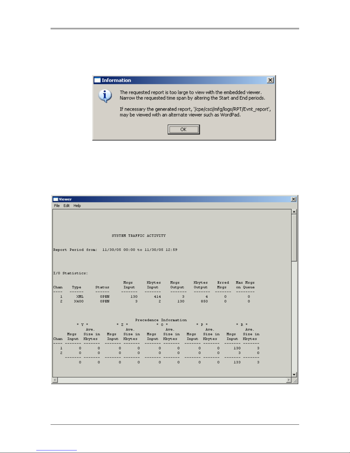
ACP-145 Gateway User's Guide
3.7.1 System Report
as WordPad to display the report. Otherwise, merely select the OK button in
the Information window, reduce (or narrow) the specified time parameters
by altering the Start and End times in the Reports window, and then select
the Create button once again to generate the requested report.
This report type option enables the operator to produce a report that
contains system-wide statistics for a specified time period. When System
Report is selected in the Report Type field (of the Reports window), the
System Traffic Activity report is displayed in a Viewer window:
This report shows I/O statistics for each CP-145 Gateway channel. All
values reflect statistics gathered during the reporting period selected in the
Reports window.
3-34 /cpe/CP-145/usm/004 (07/14)
Page 52
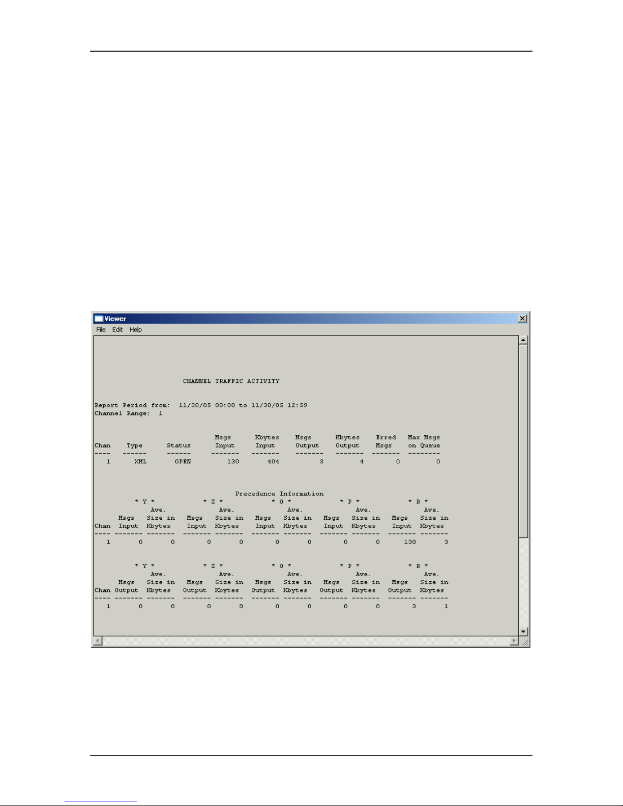
Select Print from the File menu to print the report.
3.7.2 Single Channel Report
Select Close from the File menu to exit.
Select Help to display CP-145 Gateway Help script about this window.
This example screen shows only the I/O Statistics portion of the report. Use
the horizontal and vertical scroll bars to display information outside the
display space of the window. A full System Activity Report is shown in
Appendix C. This appendix also contains a complete description of each
field in the System Activity Report.
This report type option enables the operator to produce a report that
contains channel statistics for a specified time period for a single CP-145
Gateway I/O channel. When Single Channel is selected in the Report Type
Field (of the Reports window), the Channel Traffic Activity report is
displayed in a Viewer window:
Chapter 3. System Menu
This report shows I/O statistics for a single configured CP-145 Gateway
I/O channel. All values reflect statistics gathered during the reporting period
selected in the Reports window. Use the horizontal and vertical scroll bars as
necessary to display information outside the display space of the window.
Select Print from the File menu to print the report.
/cpe/CP-145/usm/004 (07/14) 3-35
Page 53
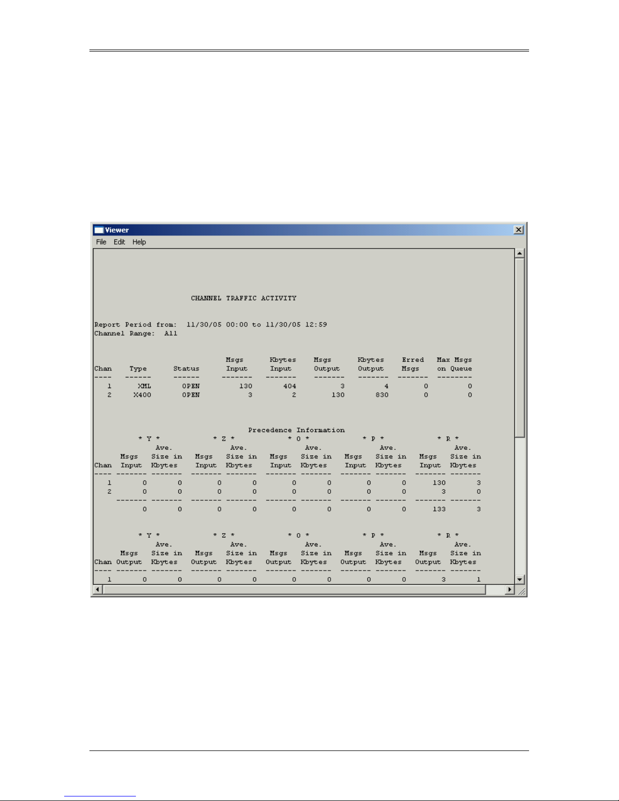
ACP-145 Gateway User's Guide
3.7.3 All Channels Report
Select Close from the File menu to exit.
Select Help to display CP-145 Gateway Help script about this window.
See Appendix C for a description of the fields in this report.
This report type option enables the operator to produce a report that
contains channel statistics for a specified time period. When All Channels is
selected in the Report Type field (of the Reports window), the Channel
Traffic Activity report is displayed in a Viewer window:
This report shows I/O statistics for all configured CP-145 Gateway I/O
channels. Identical information is displayed for a single channel described
above. All values reflect statistics gathered during the reporting period
selected in the Reports window. Use the horizontal and vertical scroll bars as
necessary to display information outside the display space of the window.
Select Print from the File menu to print the report.
Select Close from the File menu to exit.
3-36 /cpe/CP-145/usm/004 (07/14)
Page 54
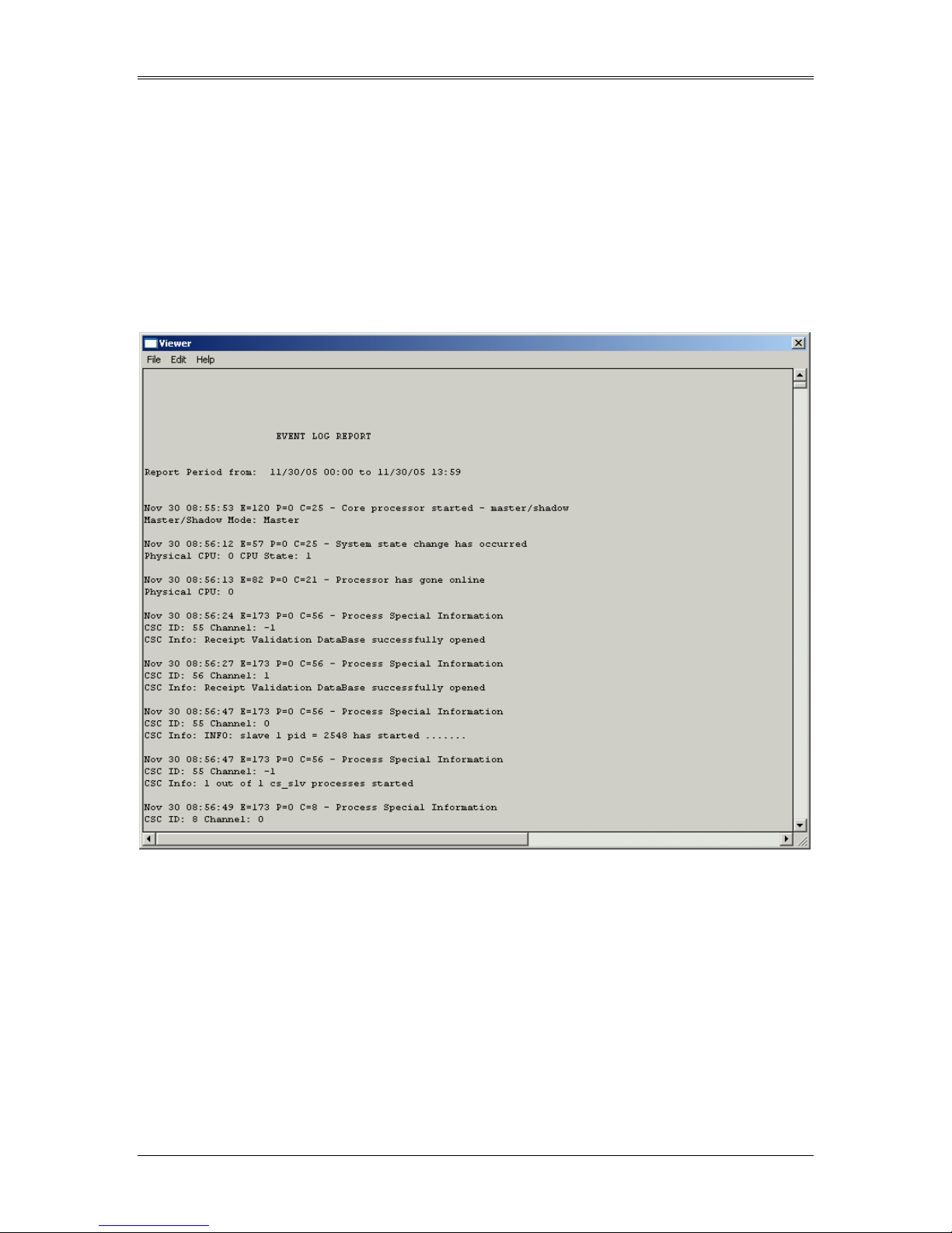
Select Help to display CP-145 Gateway Help script about this window.
3.7.4 Event Log Report
See Appendix C for a description of the fields in this report.
This report type option enables the operator to generate an event log (audit)
report for a specified time period. A subset of these events is printed on the
event log printer during normal system operation. When Event Log is
selected in the Report Type field (of the Reports window), the Event Log
Report is displayed in a Viewer window:
Chapter 3. System Menu
This report shows a list of event messages that were generated during the
selected reporting period. Event records are listed in chronological order.
Use the horizontal and vertical scroll bars as necessary to display information
outside the display space of the window.
Select Print from the File menu to print the report.
Select Close from the File menu to exit.
Select Help to display CP-145 Gateway Help script about this window.
See Appendix C for a description of the content of this report.
/cpe/CP-145/usm/004 (07/14) 3-37
Page 55
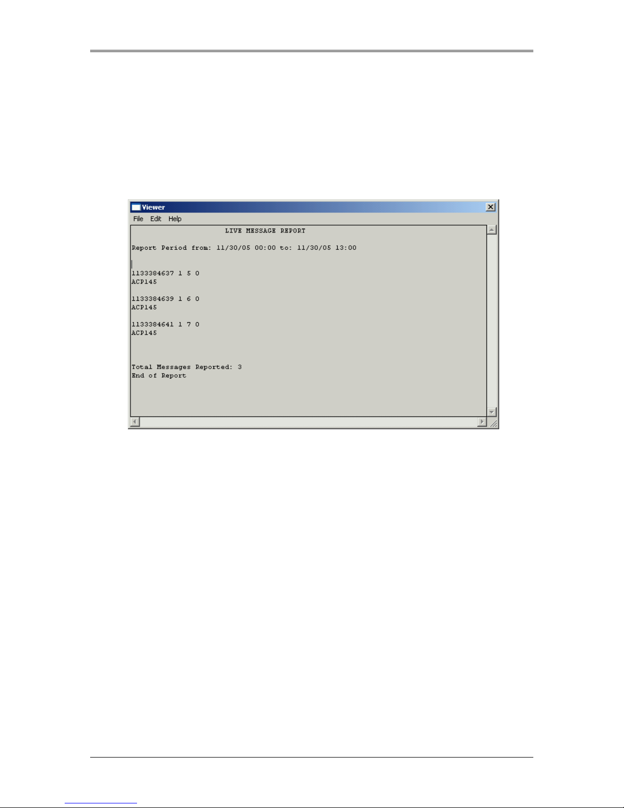
ACP-145 Gateway User's Guide
3.7.5 Live Messages Report
3.7.6 Security Log Report
This report type option enables the operator to generate a live message
report containing information about each message that is still within the
confines of the CP-145 Gateway. In other words, it shows messages that
have been received by the CP-145 Gateway, but have not yet been
transmitted out of the CP-145 Gateway. When Live Messages is selected in
the Report Type field (of the Reports window), the Live Messages Report is
displayed in a Viewer window:
Select Print from the File menu to print the report.
Select Close from the File menu to exit.
Select Help to display CP-145 Gateway Help script about this window.
This report type option enables the operator to generate a security log report
containing all system and channel security modifications for a given time
period. When the CP-145 configuration utility is used to modify either the
system security level or the channel security parameters, an entry is made to a
security log file that describes the modification. Security modifications do not
take effect until the CP-145 is restarted. When the CP-145 is restarted, it
reads the security log file and creates an individual CP-145 event for each
entry in the log file. The security log report displays all the security log events
for a given time period.
When Security Log is selected in the Report Type field (of the Reports
window), the Security Log Report is displayed in a Viewer window:
3-38 /cpe/CP-145/usm/004 (07/14)
Page 56
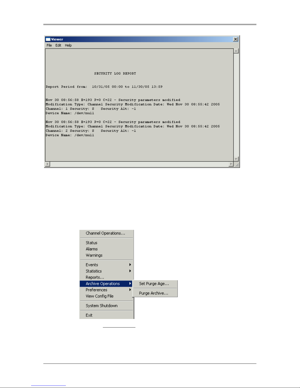
Chapter 3. System Menu
3.8
ARCHIVE OPERATIONS
Select Print from the File menu to print the report.
Select Close from the File menu to exit.
Select Help to display CP-145 Gateway Help script about this window.
When Archive Operations is selected from the System Menu, the Archive
Operations sub-menu is displayed:
Select Set Purge Age to specify the age at which information in the
Message Archive, statistics log files, and event log files will be
automatically purged from the CP-145 Gateway.
/cpe/CP-145/usm/004 (07/14) 3-39
Page 57
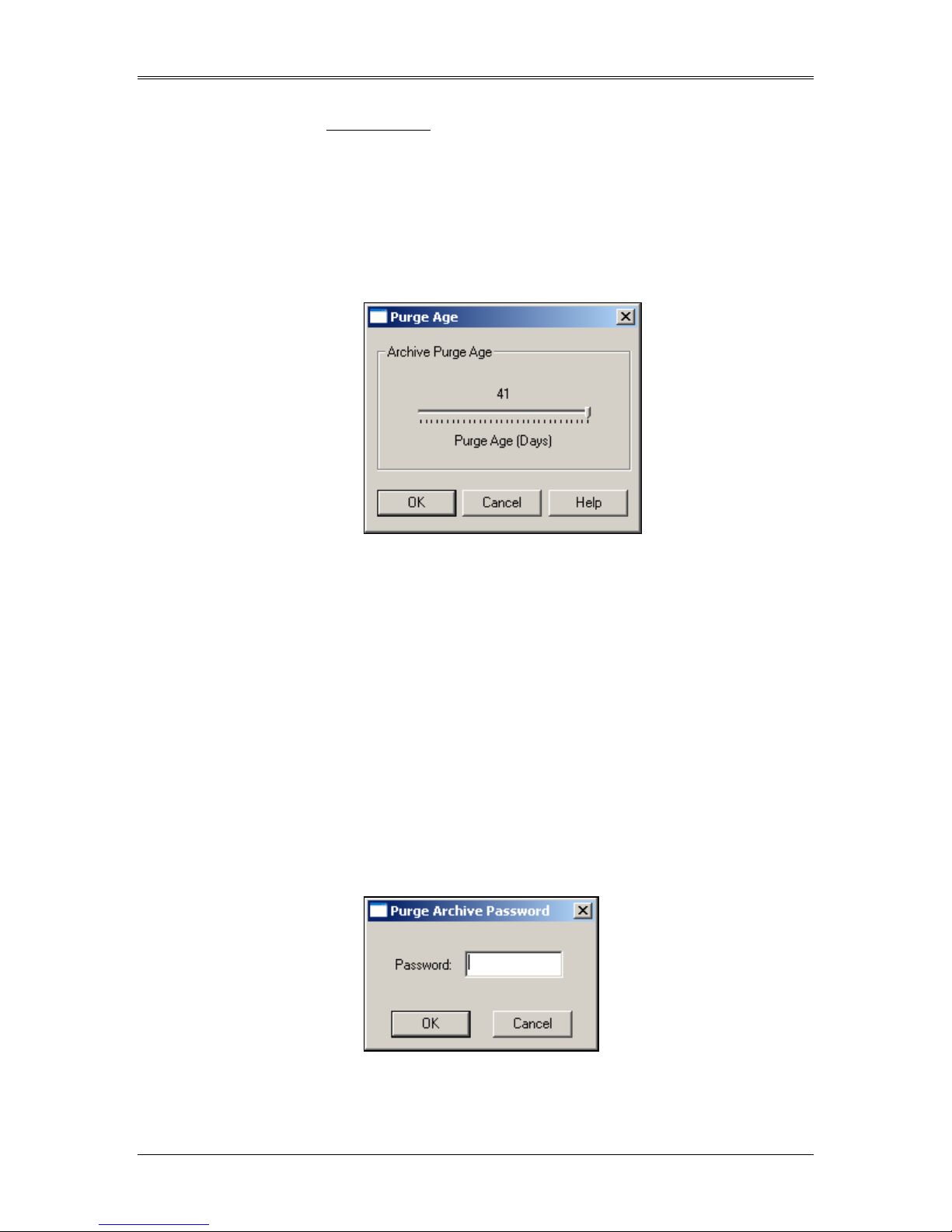
ACP-145 Gateway User's Guide
3.8.1 Set Purge Age
3.8.2 Purge Archive
Select Purge Archive to purge all statistics log files, event log files, and
the Message Archive.
This sub-menu option enables the operator to specify the age (in days) at
which information in the Message Archive, statistics files and event log files
will be automatically purged. When Set Purge Age is selected from the
Archive Operations sub-menu the Purge Age window is displayed:
Use the slider bar in the Purge Age field to specify the desired number of
days in the range 10-41.
Select the OK button to continue.
Select the Cancel button to exit this window without changing the purge
age.
Select the Help button to display CP-145 Gateway Help script about this
window.
Following an OK selection, a Response window indicates the results of the
request: SUCCESS or FAIL. Select the OK button to exit.
This sub-menu option enables the operator to purge all statistics log files,
event log files, and the Message Archive. When Purge Archive is selected
from the Archive Operations sub-menu the Password window is displayed:
Enter the password required to purge the statistics log files, the event log
files, and the Message Archive.
3-40 /cpe/CP-145/usm/004 (07/14)
Page 58
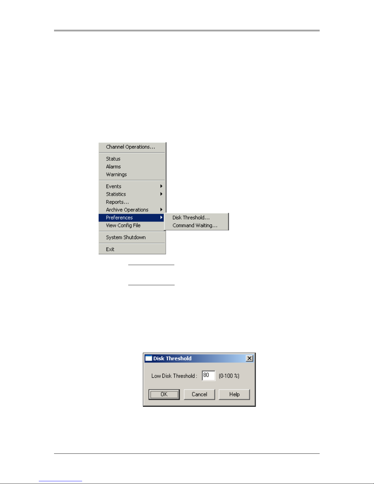
3.9
PREFERENCES
3.9.1 Disk Threshold
Select the OK button to continue.
Select the Cancel button to exit this window without purging any files.
Following a valid password entry, an OK selection, and a deletion
confirmation, the CP-145 will purge all statistics log files, event log files, and
the Message Archive. When the command is complete, all accumulated
statistics/message data will be cleared permanently.
When Preferences is selected from the System Menu, the Preferences submenu is displayed:
Chapter 3. System Menu
Select Disk Threshold to specify a low disk threshold notification
parameter.
Select Command Wait to specify the maximum amount of time to wait
for a command response.
This sub-menu option enables the operator to specify a low disk threshold
notification parameter. (Upon reaching the threshold, an event will be
periodically generated indicating this fact.) When Disk Threshold is selected
from the Preferences sub-menu, the Disk Threshold window is displayed:
Select the OK button to continue.
Select the Cancel button to exit this window without changing the disk
threshold.
/cpe/CP-145/usm/004 (07/14) 3-41
Page 59
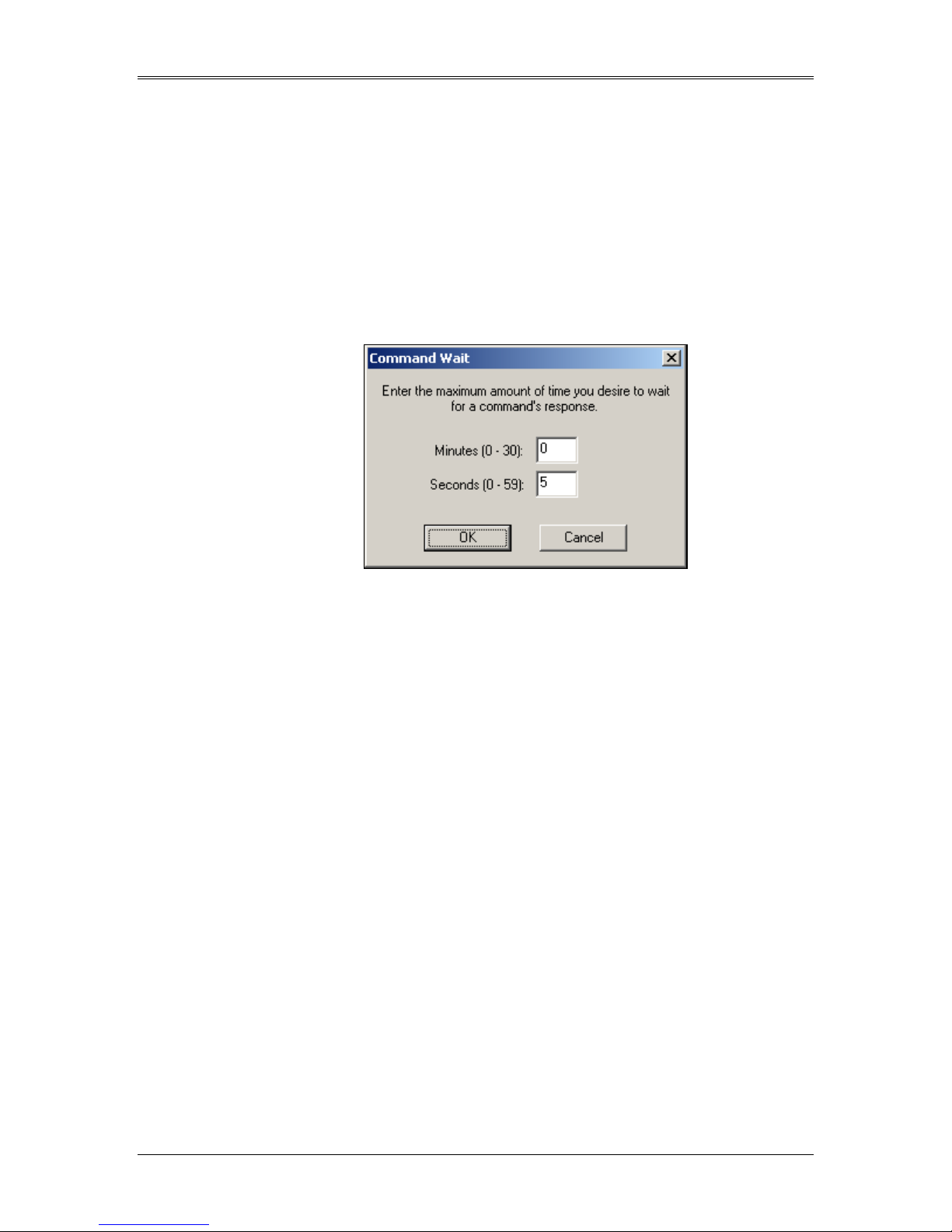
ACP-145 Gateway User's Guide
3.9.2 Command Wait
3.10 VIEW CONFIG FILE
Select the Help button to display CP-145 Gateway Help script about this
window.
This sub-menu option enables the operator to specify the maximum amount
of time to wait for a command’s response. If a command has yet to be
processed upon reaching this parameter, a notification is displayed indicating
this fact and requesting whether the operator wants to continue waiting.
When Command Wait is selected from the Preferences sub-menu the
Command Wait window is displayed:
Enter the desired time parameters in the Minutes and Seconds field in the
range 0-30 and 0-59, respectively.
Select the OK button to continue.
Select the Cancel button to exit this window without changing the
command wait parameters.
This sub-menu option enables the operator to view the CP-145
Configuration File. When View Config File is selected from the System
Menu, the CP-145 Configuration File is displayed in the System
Configuration window:
3-42 /cpe/CP-145/usm/004 (07/14)
Page 60
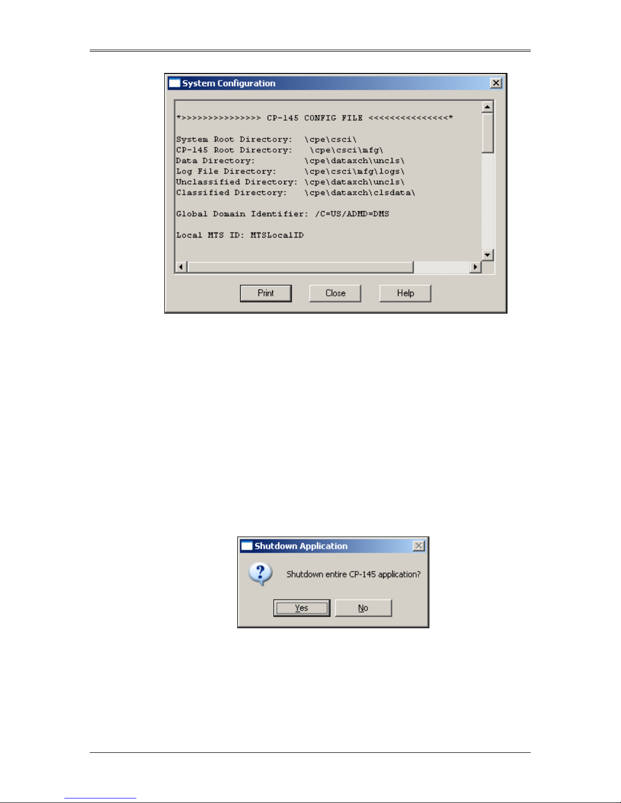
Chapter 3. System Menu
3.11 SYSTEM SHUTDOWN
Use the vertical scroll bar to view information outside the display space of
the window.
Select the Print button to print the file.
Select the Close button to exit this window.
Select the Help button to display CP-145 Gateway Help script about this
window.
See the CP-145 Installation and Administration Manual for a description of the
information in the CP-145 Configuration File.
This sub-menu option enables the operator to gracefully shutdown the entire
system. When System Shutdown is selected from the System Menu, the
Shutdown Application window is displayed:
Select the Yes button to continue with the shutdown operation.
Select the No button if you do not wish to shut down the system at this
time.
/cpe/CP-145/usm/004 (07/14) 3-43
Page 61

ACP-145 Gateway User's Guide
3.12 EXIT
This sub-menu option enables the operator to exit the CP-145 Gateway User
Interface. When Exit is selected from the System Menu, the CP-145
Gateway Main Window is closed.
3-44 /cpe/CP-145/usm/004 (07/14)
Page 62

Chapter 3. System Menu
C
O M
M
P O
W
E
R
/cpe/CP-145/usm/004 (07/14) 3-45
Page 63
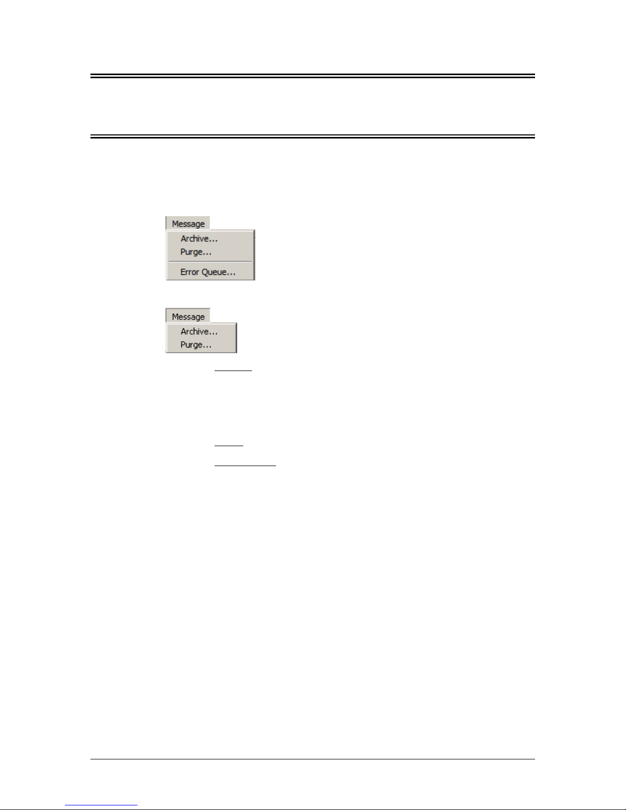
Chapter 4
MESSAGE MENU
4.1
ARCHIVE
This chapter describes the Message Menu. When Message is selected from
the menu bar, a pull-down menu is displayed:
CP-145(L):
CP-145(F):
Select Archive to retrieve messages from the Message Archive based on
time range or on Message UID or Message Transfer System (MTS) ID
(both of which are collectively referred to as “Message IDs”); view
system events and message text associated with a retrieved Message ID;
and retransmit a retrieved message.
Select Purge to purge a specific message from the Message Archive.
Select Error Queue to display, view, edit, and delete messages queued to
the MEQ field in the CP-145(L) Main window.
This sub-menu option enables the operator to retrieve messages from the
Message Archive based on time range or on Message UID or X400 ID (both
of which are collectively referred to as “Message IDs”, as mentioned above);
view system events and message text associated with a retrieved Message ID;
retransmit a retrieved message. When is selected Archive from the Message
Menu (or the Archive button is selected in the ACP-145 Gateway Main
Window), the Message Archive window is displayed:
CP-145(L):
/cpe/CP-145/usm/004 (07/14) 4-1
Page 64
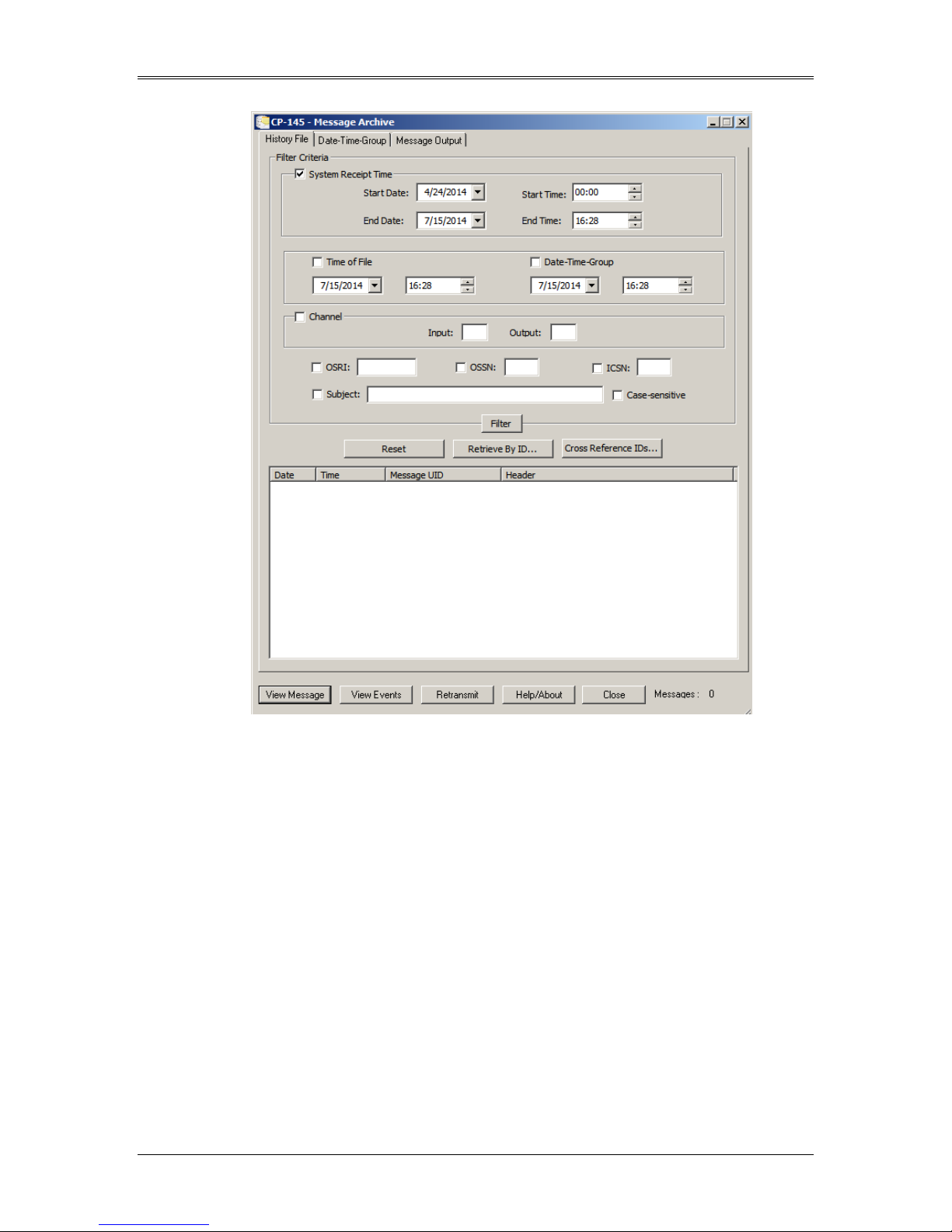
CP-145 Gateway User’s Guide
Select the History File tab to search the message archive History File.
Select the Message Output tab to search the Message Output history.
System Receipt Time:
This checkbox indicates the fields in the frame will
be used in the filter. This field is checked by default each time the Message
Archive is opened.
Start Date/Time: This field indicates the start date and time for the message
retrieval operation.
End Date/Time: This field indicates the end date and time for the message
retrieval operation.
NOTE: By default, the start and end times will reflect the entire range of
the Message Archive.
Time of File: This checkbox indicates that the Time of File fields will be
used in the filter operation. The associated date and time fields represent the
message Time of File.
4-2 /cpe/CP-145/usm/004 (07/14)
Page 65

Chapter 4. Message Menu
Date-Time Group: This checkbox indicates that the Date-Time Group fields
will be used in the filter operation. The associated date and time fields
represent the message Date-Time Group.
Channel: This checkbox indicates the fields in the frame will be used in the
filter operation.
Input Channel: This field indicates the number of the channel that received
the message.
Output Channel: This field indicates the number of the channel that output
the message.
OSRI: This field indicates the OSRI attribute from the message. The
checkbox indicates the OSRI should be used in the filter.
OSSN: This field indicates the OSSN attribute from the message. The
checkbox indicates the OSSN should be used in the filter.
ICSN: This field indicates the Input Channel Serial Number attribute from
the Message UID. The checkbox indicates the ICSN should be used in the
filter.
Subject: This checkbox indicates that the Subject field will be used in the
filter operation. The associated field represents the message subject text that
will be used in the search.
Case-sensitive: This checkbox indicates the Subject field search will be
case-sensitive.
If a filter operation retrieves messages they are list in the display box at the
bottom of the Message Archive window. The following message parameters
for each message are listed:
Date: This field indicates the operating system date that was assigned
to the message when it was received.
Time: This field indicates the operating system time that was
assigned to the message when it was received.
Message UID: This field indicates the message unique identifier
(UID) that was assigned to the message when it was received.
Header: This field indicates the message header.
Messages: This field indicates the total number of messages retrieved during
the filter operation.
Select the Filter button to execute a search based on time range and
other optional search criteria (e.g., input/output channel number). See
“Filter Message UID Retrieval based on Time Range” below.
Select the Reset button to reset this window.
Select the Retrieve by ID… button to enter a known ID and retrieve
the message. See “Retrieve by ID” below
Select the Cross Reference IDs button to enter a known Message ID
/cpe/CP-145/usm/004 (07/14) 4-3
Page 66
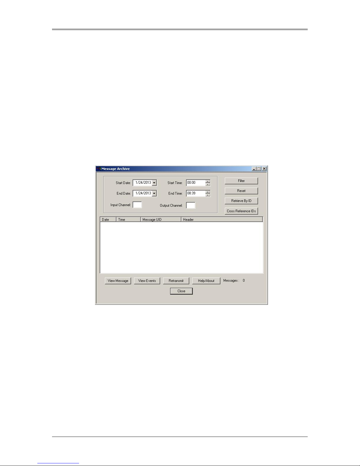
CP-145 Gateway User’s Guide
and retrieve the other two Message Ids. See “Cross Reference IDs”
below.
Select the View Message button to display the text associated with a
retrieved Message ID. See “View Message” below.
Select the View Events button to display system events associated with a
retrieved message ID. See “View Events” below.
Select the Retransmit button to retransmit a retrieved message. See
“Retransmit Message” below.
Select the Close button to exit this window.
CP-145(F):
Start Date/Time: This field indicates the start date and time for the message
retrieval operation.
End Date/Time: This field indicates the end date and time for the message
retrieval operation.
NOTE: By default, the start and end times will reflect Day 1 and Day 31 of
the Message Archive.
Input Channel: This field indicates the number of the channel that received
the message.
Output Channel: This field indicates the number of the channel that output
the message.
Date: This field indicates the operating system date that was assigned to the
message when it was received.
4-4 /cpe/CP-145/usm/004 (07/14)
Page 67

Chapter 4. Message Menu
4.1.1 “Filter” Message UID Retrieval based on Time
Range
Time: This field indicates the operating system time that was assigned to the
message when it was received.
Message UID: This field indicates the message unique ID (UID) that was
assigned to the message when it was received.
Header: This field indicates the message header.
Messages: This field indicates the total number of messages retrieved during
the search operation.
Select the Filter button to execute a search based on time range and
other optional search criteria (e.g., input/output channel number). See
“Filter Message UID Retrieval based on Time Range” below.
Select the Retrieve By ID button to search for a known Message UID
or X400 ID. See “Retrieve by Message ID” below.
Select the Cross Reference IDs button to enter a known Message ID
and retrieve the other two Message IDs. See the section on “Cross
Reference IDs”.
Select the View Message button to display the text associated with a
retrieved Message ID. See “View Message” below.
Select the View Events button to display system events associated with a
retrieved message ID. See “View Events” below.
Select the Retransmit button to retransmit a retrieved message. See
“Retransmit Message” below.
Select the Reset button to reset this window.
Select the Close button to exit this window.
Select the Help/About button to display a ACP-145 Help script.
The Filter button enables the operator to search for all Message UIDs
associated with a given or specified time range and other (optional) search
criteria.
Enter the desired start date/time and end date/time in the Start
Date/Start Time and End Date/End Time fields, respectively. When
specifying the start/end date, select the respective field to display a dropdown calendar from which the desired date can be specified.
/cpe/CP-145/usm/004 (07/14) 4-5
Page 68
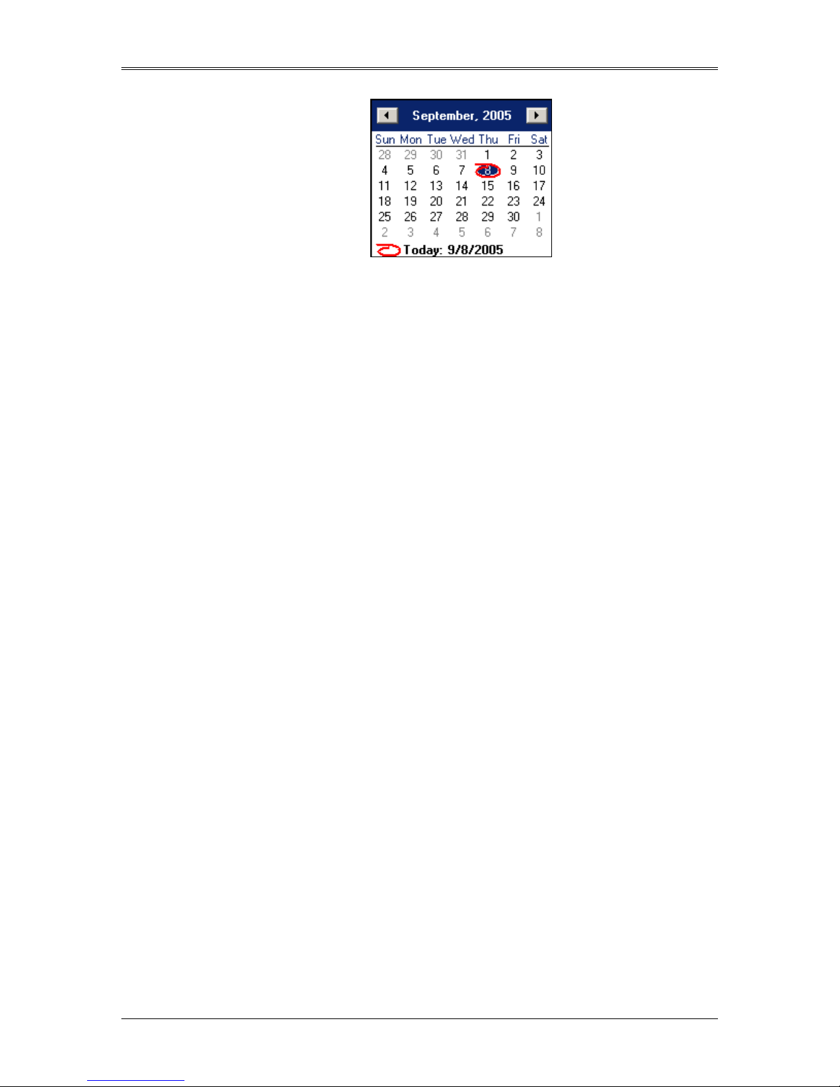
CP-145 Gateway User’s Guide
Use the left and right arrow buttons to scroll the calendar (or the month
displayed) backward and forward, respectively. (The calendar can be
changed or scrolled by left clicking the mouse over the date at the top of
the calendar, in this case “January 2001”, and then selecting the desired
month from the drop-down display list.) When scrolling backward,
scrolling cannot go beyond the purge age of the ACP-145 Gateway. (This
is the current date minus 10-41 days, depending on the purge age
currently specified for the ACP-145 Gateway. If necessary, see “Set
Purge Age” below.). The earliest date that can be selected will be
highlighted in the calendar. Thus, in the above example, January 25 is the
earliest date and January is the earliest month that can be selected.
Select (or enter) the desired start/end time in the respective Time fields.
Only the hour can be selected (or entered).
Enter an input and/or output channel number in the Input Channel
and/or Output Channel fields, respectively, to limit or constrain the
search to a specific input and/or output channel.
Select the Filter button.
Upon invoking or executing the retrieval operation, all Message UIDs
associated with the search parameters are displayed in the display area of
the Message Archive window:
4-6 /cpe/CP-145/usm/004 (07/14)
Page 69
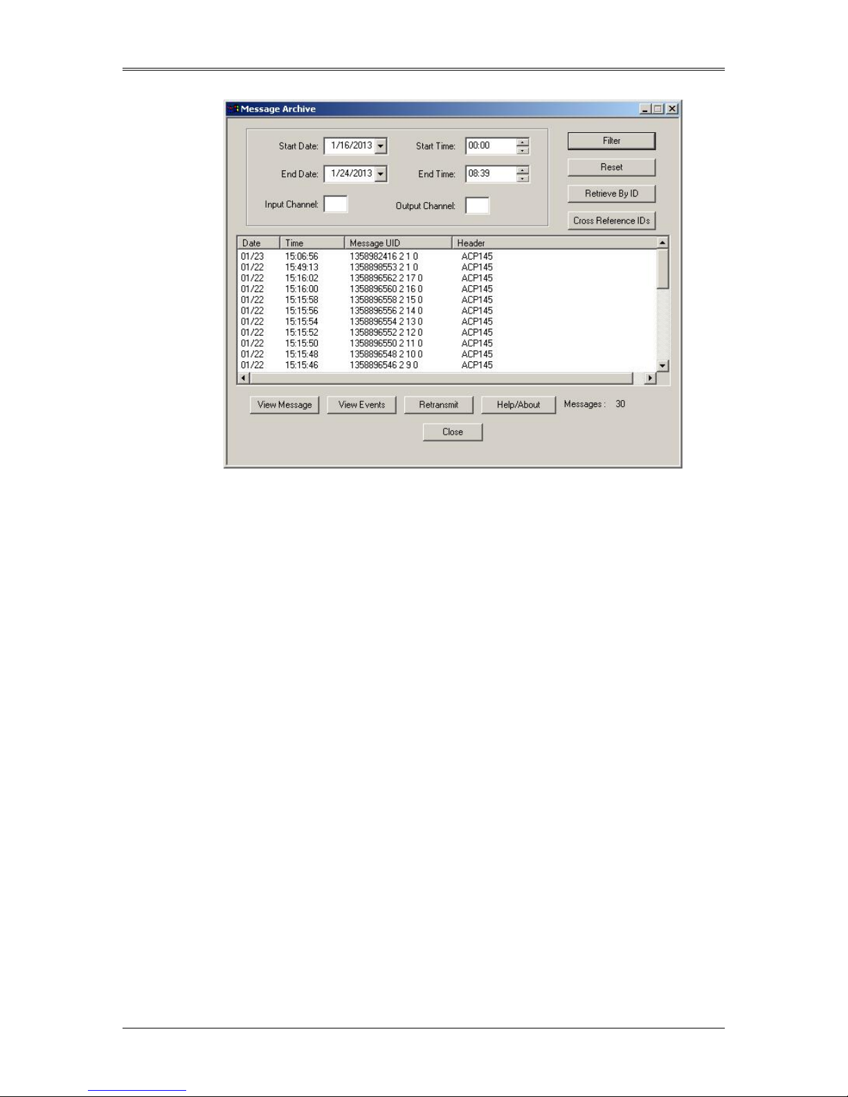
Chapter 4. Message Menu
4.1.2 Retrieve by Message ID
See “View Message”, “View Events”, and/or “Retransmit Message”
below to perform any of these related Message Archive operations.
Otherwise, perform any of the following:
Select the Reset button to reset this window.
Select the Help/About button to display a ACP-145 Gateway Help
script about this window.
Select the Close button to exit this window.
The Retrieve By ID button enables the operator to search for a specific
Message UID or X400 ID.
Select the Retrieve By ID button. The Message IDs window is
displayed:
/cpe/CP-145/usm/004 (07/14) 4-7
Page 70
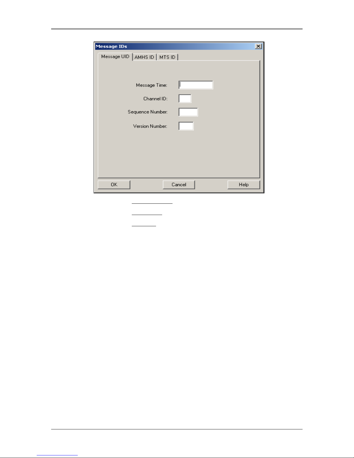
CP-145 Gateway User’s Guide
4.1.2.1 Retrieve Specific Message UID
Select the Message UID tab to retrieve a specific Message UID.
Select the AMHS ID tab to retrieve a specific AMHS ID.
Select the X400 ID tab to retrieve a specific X400 Message ID.
The Message UID tab (provided in the Message IDs window) enables the
operator to retrieve a message based on message time, channel ID, sequence
number, and version number. (If need be, this Message UID information
can be obtained from the event log data that is printed on the event log
printer or in an event log report.) When the Message UID tab is selected,
the following retrieval fields are displayed (as shown in the above window).
Enter information in these fields to identify the Message UID to be
retrieved.
Message Time: This field identifies the operating system time-stamp that
was assigned to the message when it was received.
Channel ID: This field identifies the number of the channel that received the
message.
Sequence Number: This field identifies the sequence number that was
assigned to the message when it was received.
Version Number: This field identifies the version number of the message.
Select the OK button to continue.
Select the Cancel button to exit this window.
Select the Help button to display a ACP-145 Gateway Help script about
4-8 /cpe/CP-145/usm/004 (07/14)
Page 71
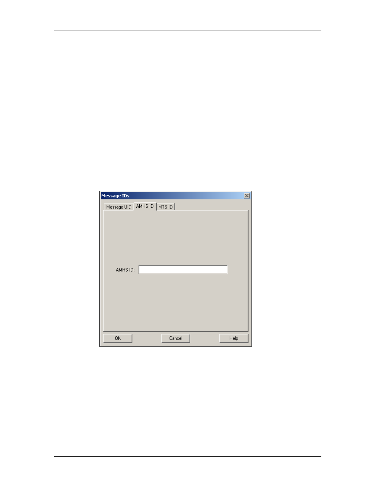
this window.
4.1.2.2 Retrieve Specific AMHS ID
4.1.2.3 Retrieve Specific MTS ID
Following an OK selection, the retrieved Message UID is displayed in the
Message Archive window. See “View Message”, “View Events”, and/or
“Retransmit Message” below to perform any of these related Message
Archive operations. Otherwise, perform any of the following:
Select the Reset button to reset this window.
Select the Help button to display a ACP-145 Gateway Help script about
this window.
Select the Close button to exit this window.
The AMHS ID tab provided in the Message IDs dialog enables the
operator to retrieve an input XML message based on its AMHS ID. When
the AMHS ID tab is selected, the Message IDs dialog is displayed with the
appropriate message retrieval field:
Chapter 4. Message Menu
Enter information in this field to identify the AMHS ID to be retrieved.
AMHS ID: This field identifies the AMHS ID assigned to the input XML
message.
The MTS ID tab (provided in the Message IDs window) enables the
operator to retrieve a Message Transfer System (MTS) message based on a
specific Country, Administrative Management Domain (ADMD), Private
Management Domain (PRMD), and Local ID. When the MTS ID tab is
selected the Message IDs window is re-displayed with the appropriate
/cpe/CP-145/usm/004 (07/14) 4-9
Page 72
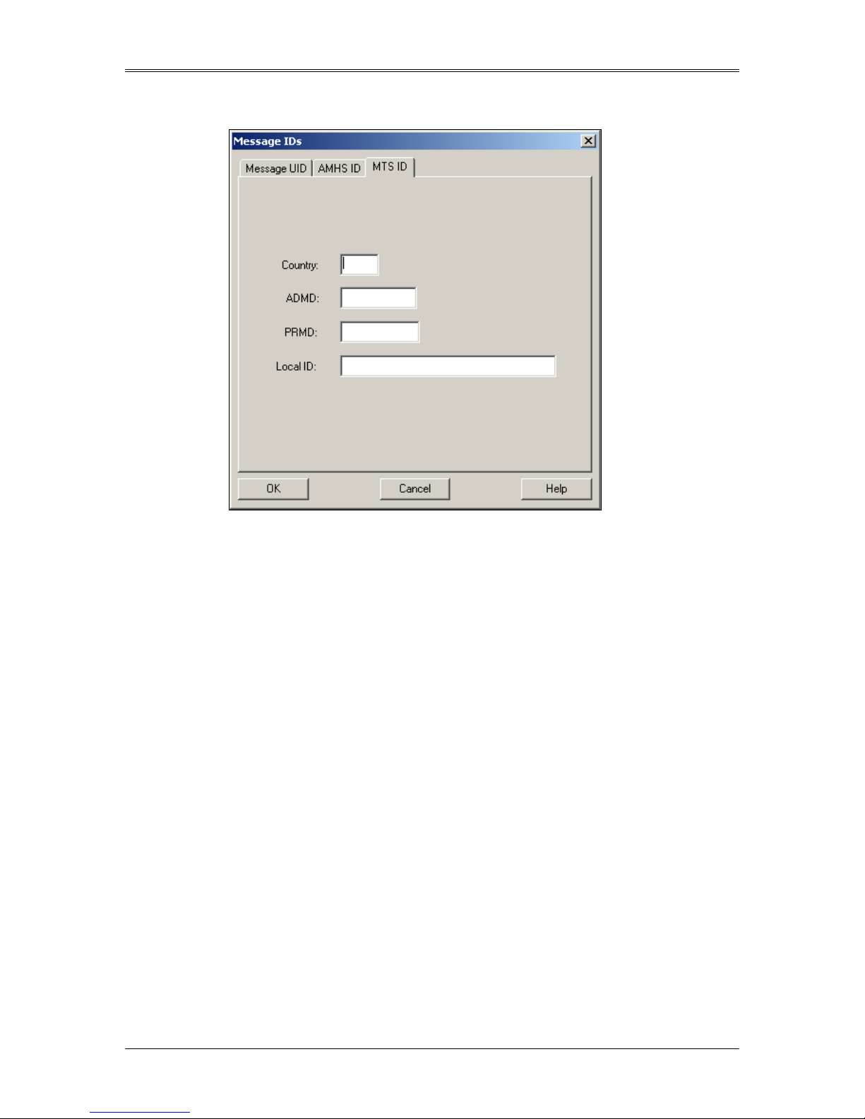
CP-145 Gateway User’s Guide
message retrieval fields:
Enter information in these fields to identify the MTS ID to be retrieved.
Country: This field identifies the MTS message originator country name.
ADMD: This field identifies the MTS message originator Administrative
Management Domain name.
PRMD: This field identifies the MTS message originator Private
Management Domain name.
Local ID: This field identifies the remaining portion of the MTS local
identifier minus the country, ADMD, and PRMD values.
Select the OK button to continue.
Select the Cancel button to exit this window.
Select the Help button to display a ACP-145 Gateway Help script about
this window.
Following an OK selection, the MTS ID is displayed in the Message
Archive window. See “View Message”, “View Events”, and/or “Retransmit
Message” below to perform any of these related Message Archive operations.
Otherwise, perform any of the following:
Select the Reset button to reset this window.
Select the Help button to display a ACP-145 Gateway Help script about
this window.
Select the Close button to exit this window.
4-10 /cpe/CP-145/usm/004 (07/14)
Page 73
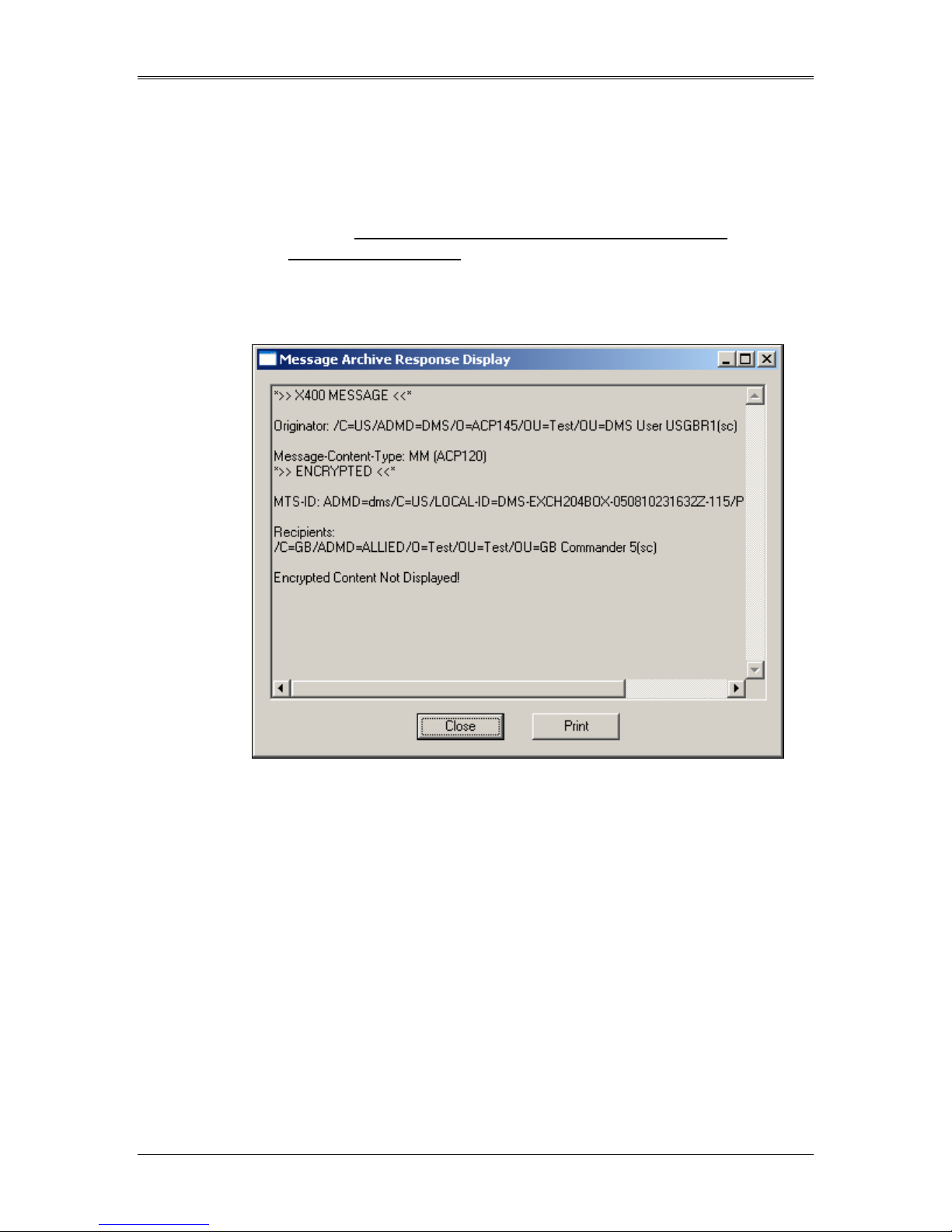
4.1.3 View Message
4.1.4 View Events
The View Message button enables the operator to view the message text
associated with a retrieved Message ID.
Retrieve the desired Message ID by performing the steps described
above in “Filter Message UID Retrieval based on Time Range” or
“Retrieve by Message ID”, depending on the required operation.
Highlight the desired Message ID in the display area of the Message
Archive window and select the View Message button. The Message
Archive Response Display window is displayed with the message text:
Chapter 4. Message Menu
Select the Print button to print this message.
Select the Close button to exit this window.
The View Events button enables the operator to display all system events
associated with a retrieved Message ID.
Retrieve the desired Message ID by performing the steps described
above in “Filter Message UID Retrieval based on Time Range” or
“Retrieve by Message ID”, depending on the required operation.
Highlight the desired Message ID in the display area of the Message
Archive window and select the View Events button. The Message
Archive Response Display window is displayed along with the
associated event information:
/cpe/CP-145/usm/004 (07/14) 4-11
Page 74

CP-145 Gateway User’s Guide
4.1.5 Retransmit Message
4.1.6 Cross Reference IDs
Select the Print button to print the event information.
Select the Close button to exit this window.
The Retransmit button enables the operator to retransmit a retrieved
message.
Retrieve the desired Message ID by performing the steps described
above in “Filter Message UID Retrieval based on Time Range” or
“Retrieve by Message ID”, depending on the required operation.
Highlight the desired Message ID in the display area of the Message
Archive window and the Retransmit button. An Information window is
displayed with the results of the request. Select the Close button to exit
the Information window.
The Cross Reference IDs button enables the operator who knows one of
the three Message IDs to search for that message and view the two other
IDs.
4-12 /cpe/CP-145/usm/004 (07/14)
Page 75
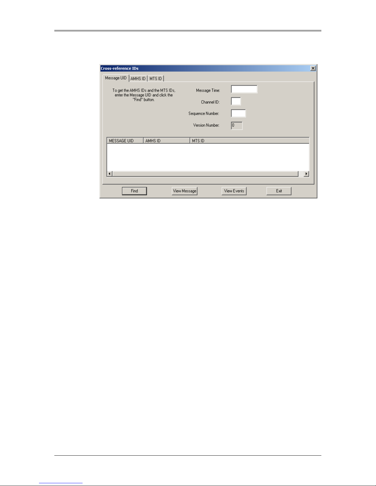
Chapter 4. Message Menu
4.1.6.1 Message UID
4.1.6.2 AMHS ID
Select the Cross Reference IDs button. The Cross Reference IDs
dialog is displayed:
Select the Message UID tab if this message ID is known.
Select the AMHS ID tab if this message ID is known.
Select the MTS ID tab if this message ID is known.
The Message UID tab provided in the Cross Reference IDs dialog enables
the operator to retrieve a message based on message time, channel ID,
sequence number, and version number and to easily view the AMHS and
MTS IDs. After the Message UID is entered select Find. All three of the
Message IDs are listed.
After highlighting the resulting message:
Select the View Message button to view the message.
Select the View Events button to view the message’s events.
Select the Exit button to exit this dialog
The AMHS UID tab provided in the Cross Reference IDs dialog enables
the operator to retrieve a message based on the AMHS ID and to easily view
the Message UID and MTS ID. After the AMHS ID is entered select Find.
All three of the Message IDs are listed.
/cpe/CP-145/usm/004 (07/14) 4-13
Page 76
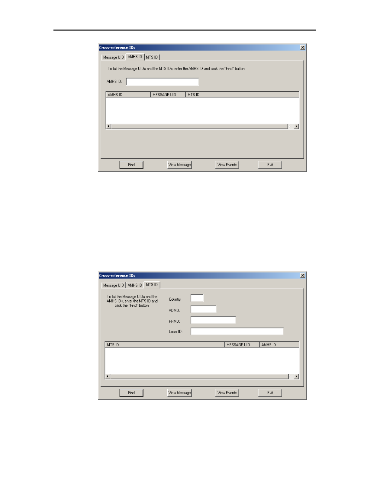
CP-145 Gateway User’s Guide
4.1.6.3 MTS ID
After highlighting the resulting message:
Select the View Message button to view the message.
Select the View Events button to view the message’s events.
Select the Exit button to exit this dialog.
The MTS ID tab provided in the Cross Reference IDs dialog enables the
operator to retrieve a message based on the MTS ID and to easily view the
Message UID and AMHS ID. After the MTS ID is entered select Find. All
three of the Message IDs are listed.
After highlighting the resulting message:
Select the View Message button to view the message.
4-14 /cpe/CP-145/usm/004 (07/14)
Page 77
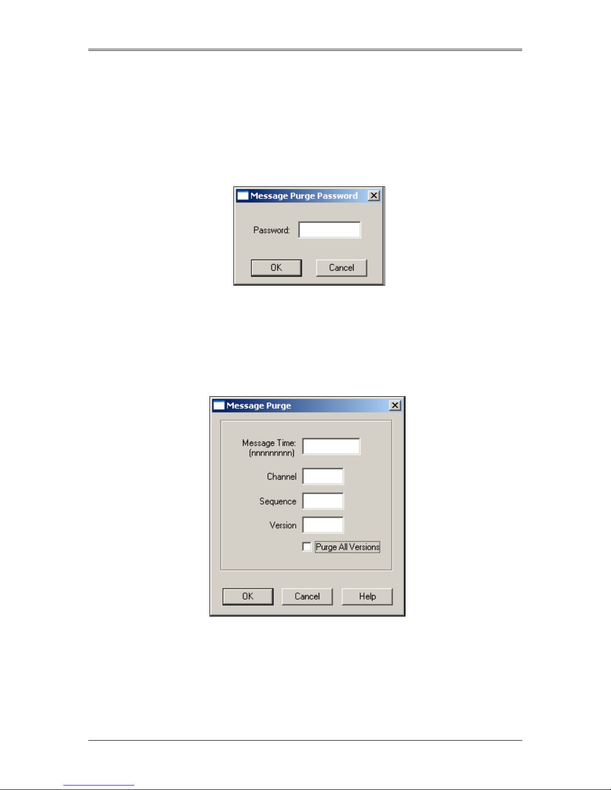
4.2
PURGE
Chapter 4. Message Menu
Select the View Events button to view the message’s events.
Select the Exit button to exit this dialog
This sub-menu option enables the operator to delete a specific message from
the Message Archive. When Purge is selected from the Message Menu, the
Password window is displayed:
Enter the password required to purge a message from the Message Archive.
Select the OK button to continue.
Select the Cancel button to exit this window without purging any
messages.
Following a valid password entry and an OK selection, the Message Purge
window is displayed:
Enter information in this window identifying the message(s) to be deleted
from the Message Archive.
Purge All Versions: Select this check box to purge all versions of the
message.
The following fields constitute the UID of the message as it was assigned by
the ACP-145 Gateway. This ID can be obtained by referring to the events
/cpe/CP-145/usm/004 (07/14) 4-15
Page 78
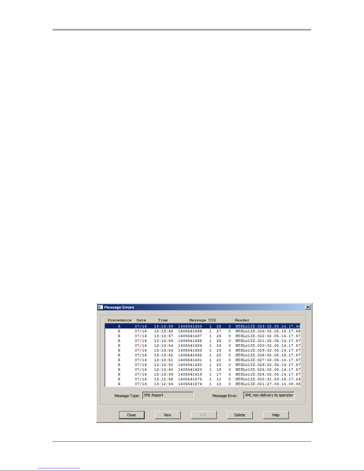
CP-145 Gateway User’s Guide
4.3
ERROR QUEUE
generated during message processing. These events can be retrieved using the
Event Log report option in the System/Reports sub-menu or from the
output on the event log printer.
Message Time: This field identifies the operating system time-stamp that
was assigned to the message when it was received.
Channel Number: This field identifies the number of the channel that
received the message.
Sequence Number: This field identifies the sequence number that was
assigned to the message when it was received.
Version Number: This field identifies the message version: “0” means
original; anything else means the message was converted from another
format.
Select the OK button to continue.
Select the Cancel button to exit this window without purging any
messages.
Select the Help button to display a ACP-145 Gateway Help script about
this window.
A Response window is displayed indicating the results of the request:
SUCCESS or FAIL. Select the Close button to exit.
This sub-menu option enables the operator to display, view, and delete
messages in the Message Error Queue (MEQ). When Error Queue is
selected from the Message Menu or when the MEQ button is selected from
the CP-145(L) Main Window, the Message Errors window is displayed:
4-16 /cpe/CP-145/usm/004 (07/14)
Page 79
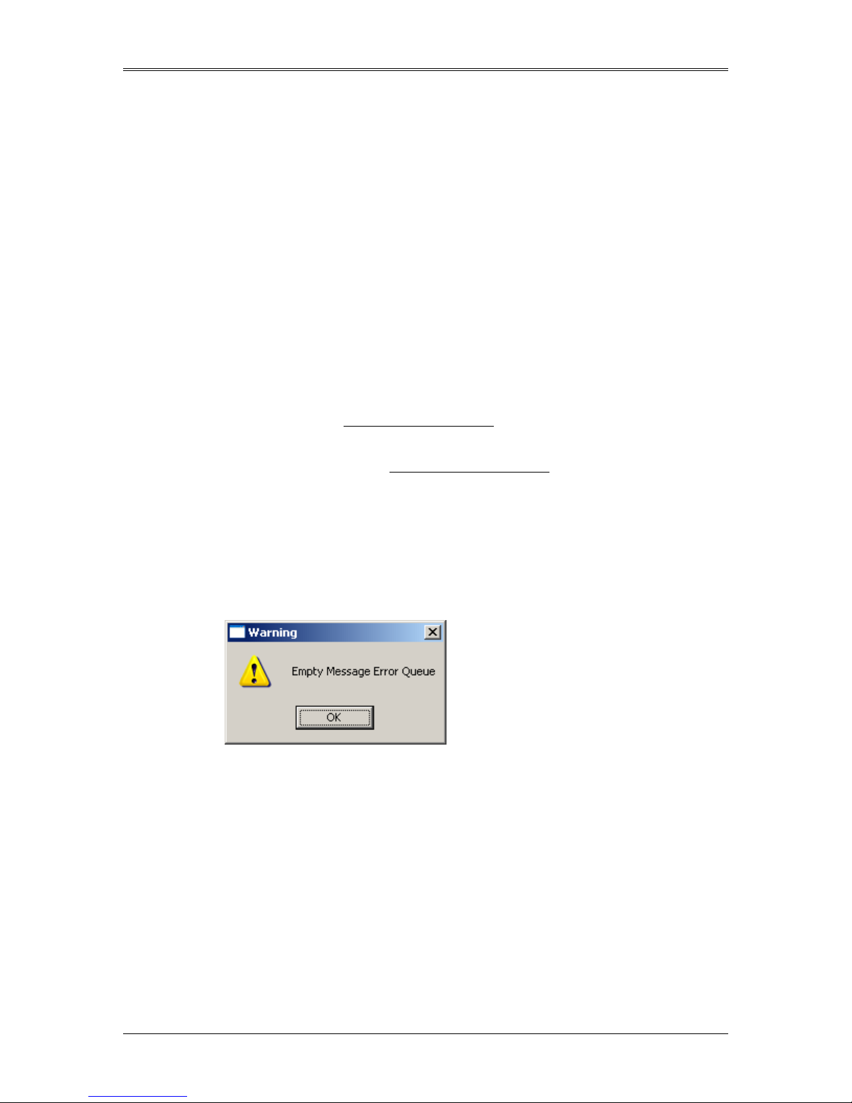
Chapter 4. Message Menu
4.3.1 View Message in MEQ
The following message related information is displayed for each message
sitting on the MEQ if it is available:
Precedence: This field indicates the precedence level of the message.
Date: This field indicates the operating system date that was assigned to the
message when it was received.
Time: This field indicates the operating system time that was assigned to the
message when it was received.
Message UID: This field indicates the Message UID that was assigned to
the message when it was received by the CP-145(L).
Header: This field indicates the message header.
Message Type: This field indicates the type of message.
Message Error: This field indicates the type of error in the message.
Select the View button to view a selected message in the Message Errors
window. See “View Message in MEQ
Select the Delete button to delete a selected message in the Message
Errors window. See “Delete Message in MEQ
” below.
” below.
Select the Close button to exit this window.
Select the Help button to display a CP-XJP Help script about this
feature.
If no messages are on the MEQ when Error Queue is selected from the
Message Menu or when the MEQ button is selected from the CP-XJP Main
Window, the following window is displayed:
The View button in the Message Errors window (see above) enables the
operator to view the message contents of a message selected (or highlighted)
in the Message Errors window. When the View button is selected, the
Message Error – View window is displayed:
/cpe/CP-145/usm/004 (07/14) 4-17
Page 80
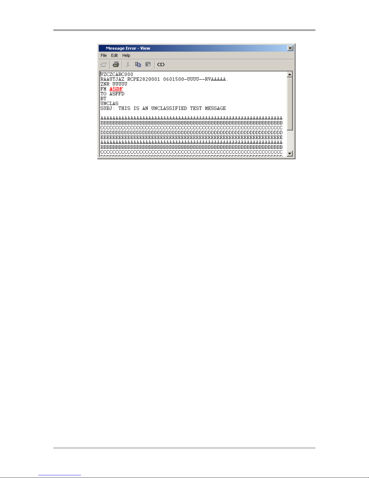
CP-145 Gateway User’s Guide
4.3.2 Delete Message in MEQ
The menus and functions in the Message Error – View window are
similar to the Message Error – Edit window; except the Dispatch, Cut,
Paste, and Delete functions are disabled. The message cannot be
modified in this window. See the section immediately below for a
description of the menu and toolbar options.
Select Quit from the File menu to exit this window, and then select the
Close button to exit the Message Errors window.
The Delete button in the Message Errors window (see above) enables the
operator to delete a message selected (or highlighted) in the Message Errors
window and remove it from the list of displayed messages.
4-18 /cpe/CP-145/usm/004 (07/14)
Page 81

Chapter 4. Message Menu
C
O M
M
P O
W
E
R
/cpe/CP-145/usm/004 (07/14) 4-19
Page 82
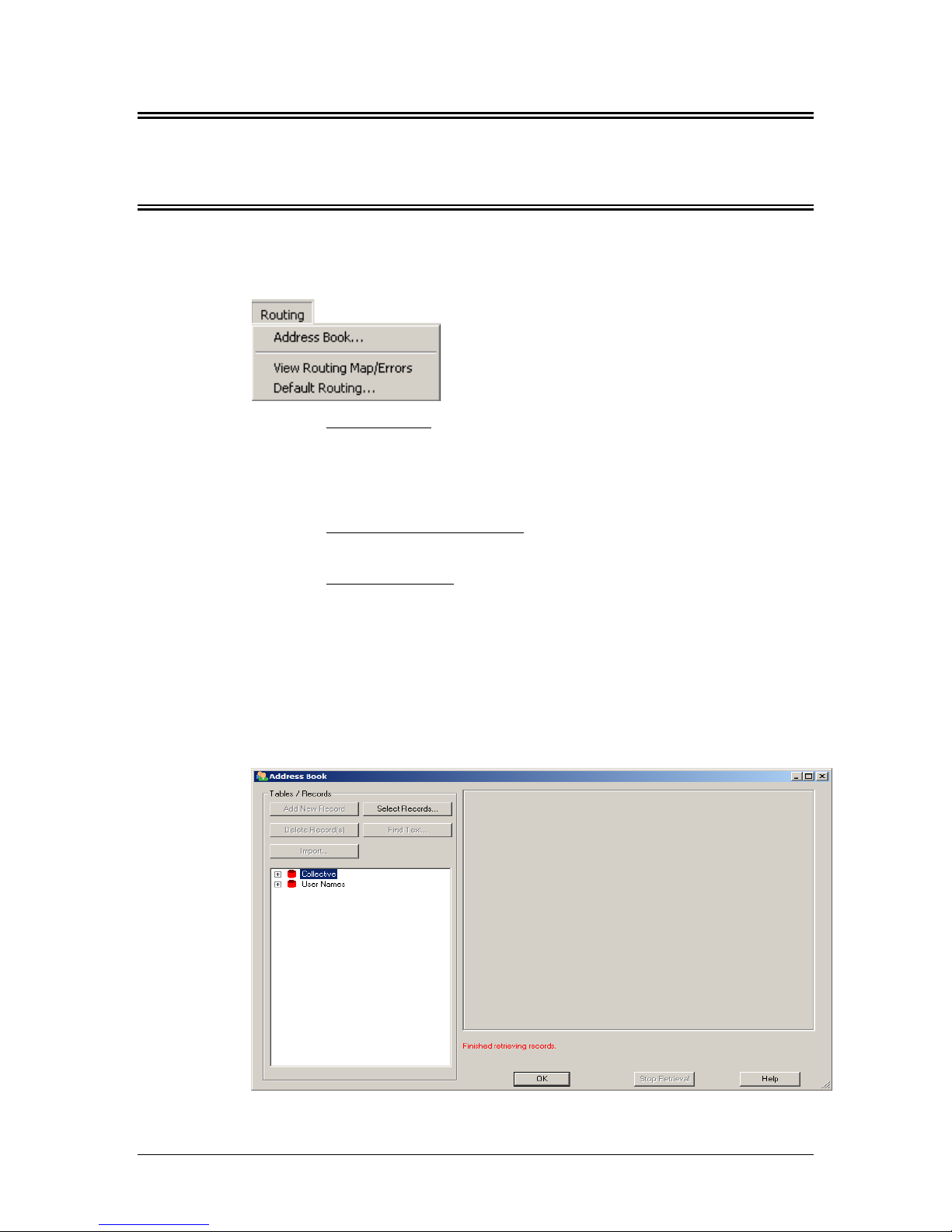
Chapter 5
ROUTING MENU
5.1
ADDRESS BOOK
This chapter describes the Routing Menu. When Routing is selected from
the menu bar, a pull-down menu is displayed:
Select Address Book to display, add, update, and delete user name
records.
NOTE: The Address Book functionality is only applicable to the ACP-145
Local Element System.
Select View Routing Map/Errors to verify the database and review the
results of the verification.
Select Default Routings to define default routes.
NOTE: The Address Book functionality is only applicable to the CP-
145(L).
This sub-menu option enables the operator to display User Names and
Collective records. When Address Book is selected from the Routing Menu,
the Address Book window is displayed:
/cpe/CP-145/usm/004 (07/14) 5-1
Page 83
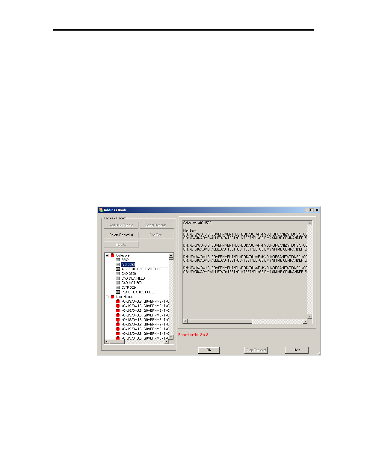
ACP-145 Gateway User's Guide
5.1.1 Display Collective and User Name Records
5.1.1.1 Display Collectives
5.1.1.2 Display User Names
This window comprises a display window for viewing Collectives and User
Names.
Select the Select Records button to access the Select Records to Display
window. This window enables selection of user name records by a
selected field (DN or PLA).
Select the + icon associated with the User Name node (in the address
book tree structure) to expand the user name tree. Conversely, select the
– icon to contract the tree. See “Display User Name Records” below.
Select the OK button to exit this window.
Select the Help button to display a CP-145 Gateway Help script about
this window.
To display Collective records, select the + icon to the left of the Collective
node in the tree structure. The Collective node is expanded to reveal the
associated collective records:
By selecting a Collective, its members DNs and ORAddresses are displayed
in the right hand pane.
To display User Name records, select the + icon to the left of the User
Names node in the tree structure. The User Names node is expanded to
reveal the associated user name records:
5-2 /cpe/CP-145/usm/004 (07/14)
Page 84
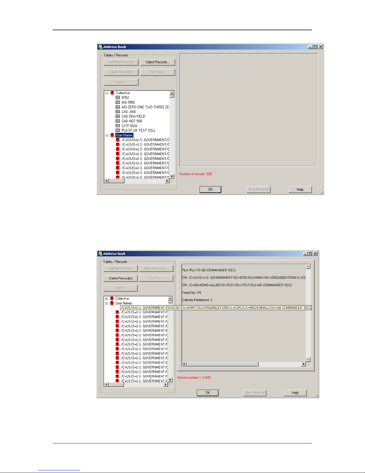
Chapter 5. Routing Menu
By default, user name records are keyed by Distinguished Name (DN)
address format. (The Select Records button can be used to retrieve and
display records keyed by PLA.) To display the entire DN or X.400 field
values for any of the user name records, use the scroll bar below right hand
pane. Allied country originators are displayed when keyed by DN. These
entries all have a Delivery Preference of 2:
/cpe/CP-145/usm/004 (07/14) 5-3
Page 85
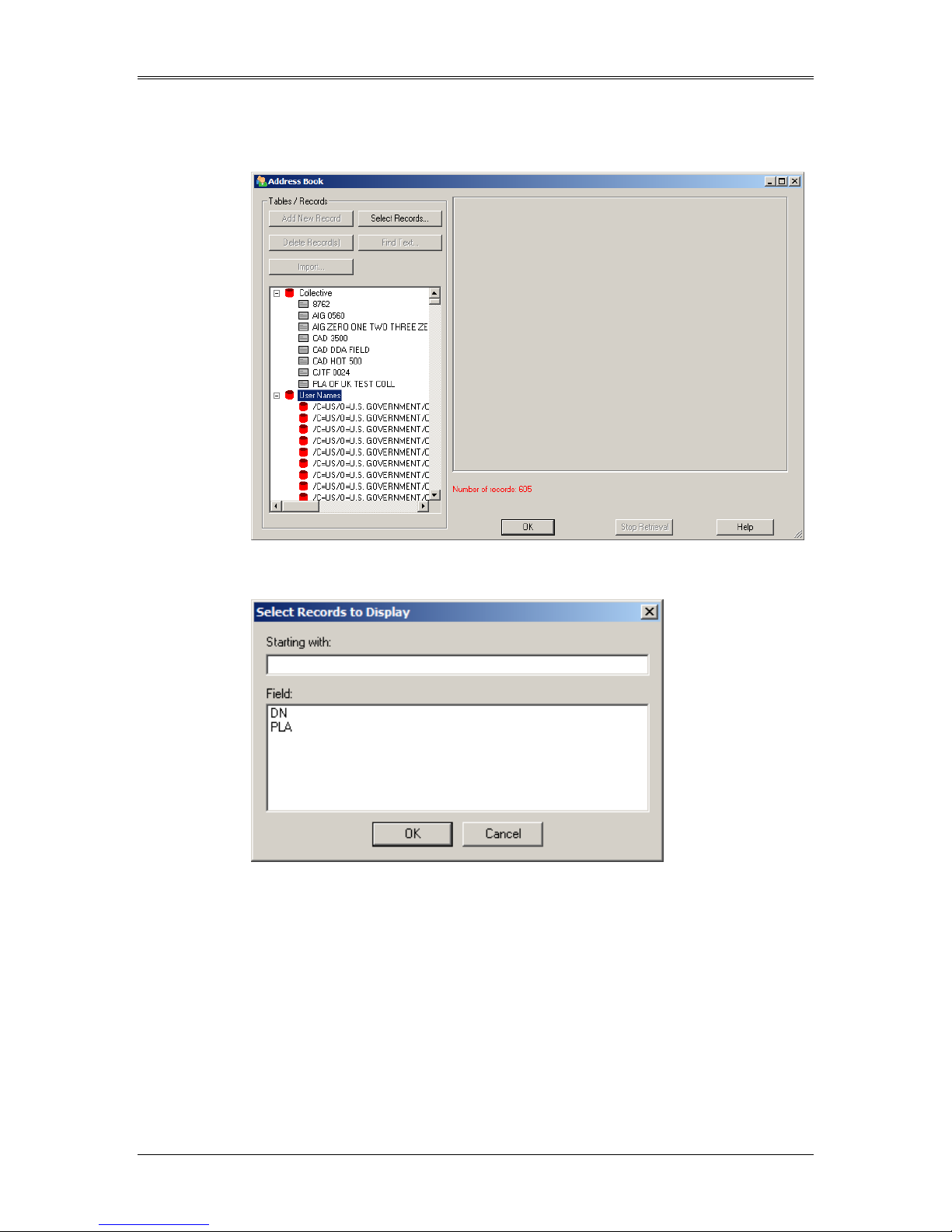
ACP-145 Gateway User's Guide
Select the User Names node to activate the Select Records button:
Select the Select Records button and the Select Records to Display
window is displayed:
Select PLA and the OK button and the User Names are displayed by PLA:
5-4 /cpe/CP-145/usm/004 (07/14)
Page 86
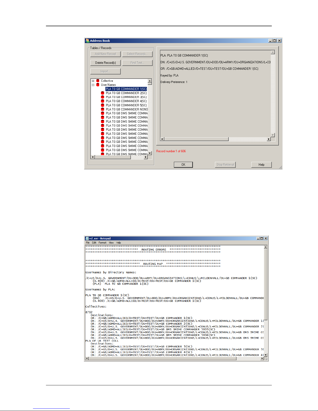
Chapter 5. Routing Menu
5.2
VIEW ROUTING MAP/ERRORS
When keyed by PLA the Allied country recipients are displayed. These User
Names have a Delivery Preference of 1.
This sub-menu option enables the operator to verify/map the database and
to display the results of the verification. When View Routing Map/Errors is
selected from the Routing menu, verification errors (if any) are displayed in
a Viewer window:
The report is organized into these sections:
/cpe/CP-145/usm/004 (07/14) 5-5
Page 87

ACP-145 Gateway User's Guide
5.3
DEFAULT ROUTINGS
Errors: If any errors or warnings occurred during the verification process,
these will be displayed first. The warnings and errors are displayed in the
following format:
Xn T description
record -> field
Where:
X = ‘E’ for error or ‘W’ for warning.
n= a number indicating the cause of the error.
description= a brief description of the error.
record= the main key of the record, such as an address of a user name record
or the list name in an address list record.
field= is the field found to be in error.
User names sorted by type: An alphabetical list is displayed for each
address type (DN or X.400). The other address forms associated with the
address are displayed below it. The preferred mode of delivery is identified
by an asterisk next to the address.
Select Print from the File menu to print the report.
Select Close from the File menu to exit.
Select Help to display a ACP-145 Gateway Help script about this
window.
This sub-menu option enables the operator to define default Routing
Indicators that will be used when the CP-145 cannot determine where a
particular message should be routed. When Default Routings is selected
from the Routing Menu, the Default Routings window is displayed:
5-6 /cpe/CP-145/usm/004 (07/14)
Page 88
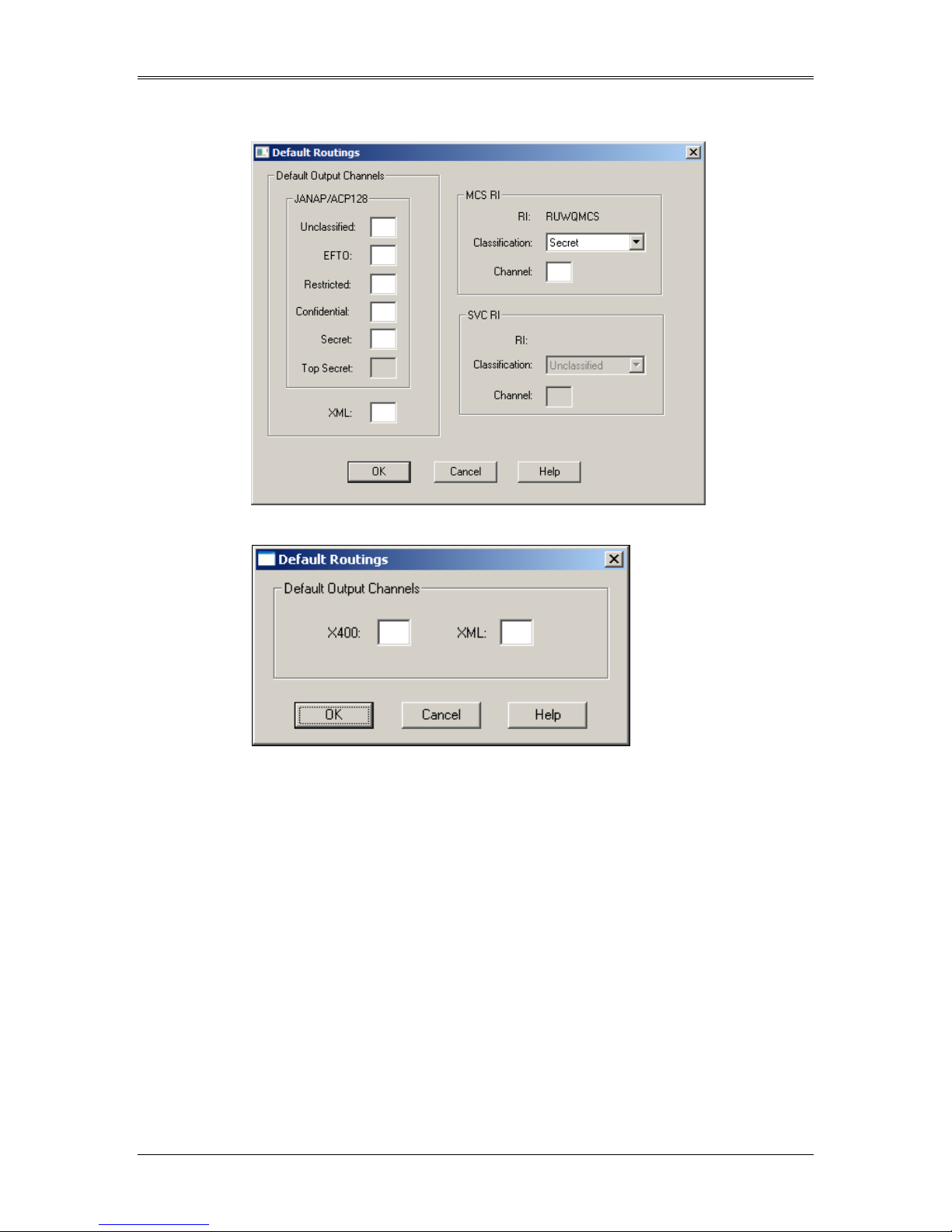
CP-145(L):
CP-145(F):
Chapter 5. Routing Menu
JANAP-128, X.400 and XML: The default channels for the various message
formats for output need to be specified.
Select the OK button to exit this window and save the defined default
route.
Select the Cancel button to exit this window without saving the default
route.
Select the Help button to display a CP-145 Gateway Help script about
this window.
/cpe/CP-145/usm/004 (07/14) 5-7
Page 89
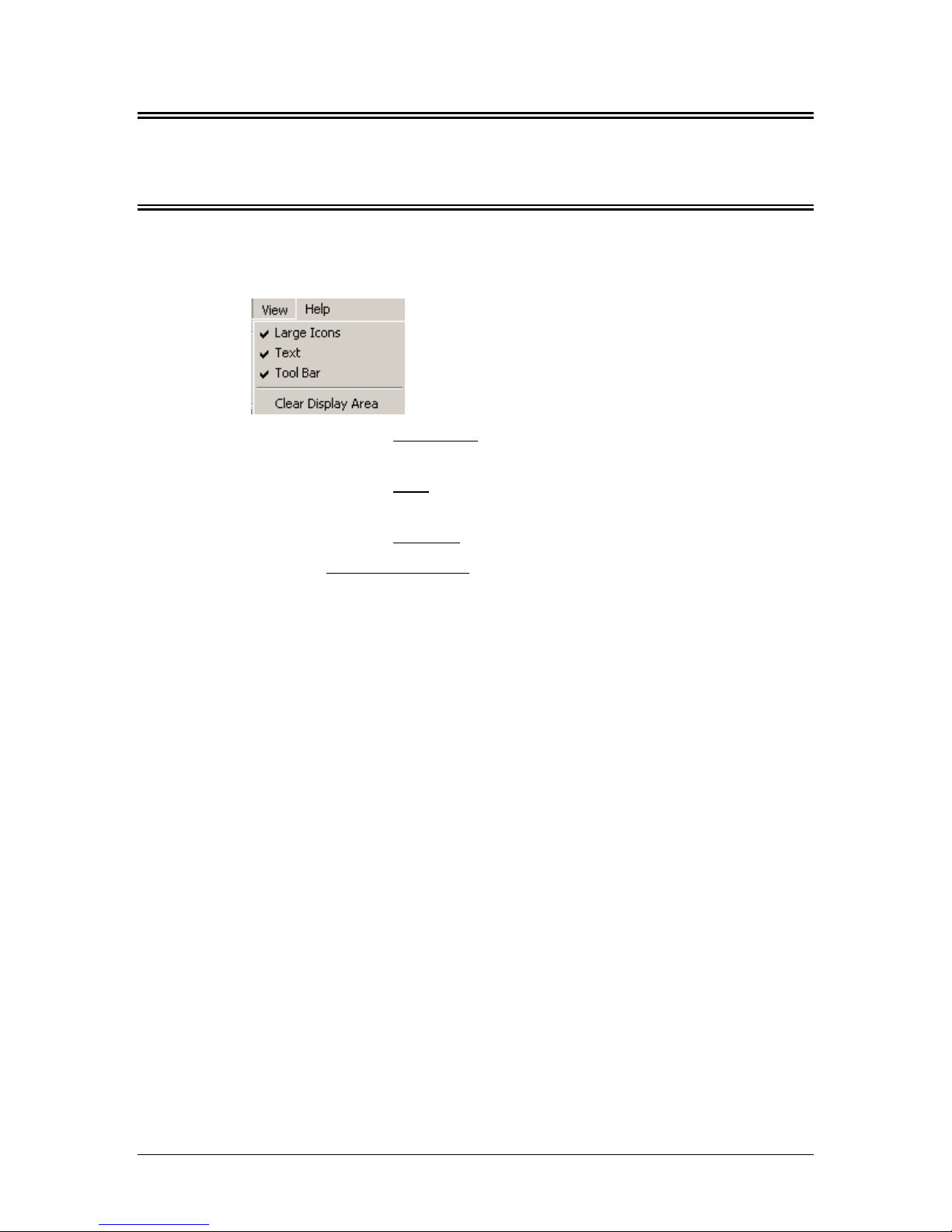
Chapter 6
VIEW MENU
6.1
LARGE ICONS
6.2
TEXT
This chapter describes the View Menu. When View is selected from the
menu bar, a pull-down menu is displayed:
Select/deselect Large Icons to display large/small buttons in the Tool
Bar.
Select/deselect Text to display/remove descriptive text strings in/from
the Tool Bar buttons.
Select/deselect Tool Bar to display/remove the Tool Bar.
Select Clear Display Area to clear information from the ACP-145
Gateway Main Window display area.
This sub-menu option enables the operator to display large or small Tool Bar
buttons (provided that the Tool Bar is currently active). When Large Icons is
selected or deselected from the View Menu, either large or small Tool Bar
buttons are displayed in the Tool Bar.
This sub-menu option enables the operator to display/remove descriptive
text strings in/from Tool Bar buttons (provided that the Tool Bar is
currently active). When Text is selected or deselected from the View Menu,
the text strings are either displayed in or removed from the Tool Bar. Thus,
if both Tool Bar and Text are selected (i.e., active), both the Tool Bar and
the associated text strings are displayed:
/cpe/CP-145/usm/004 (07/14) 6-1
Page 90
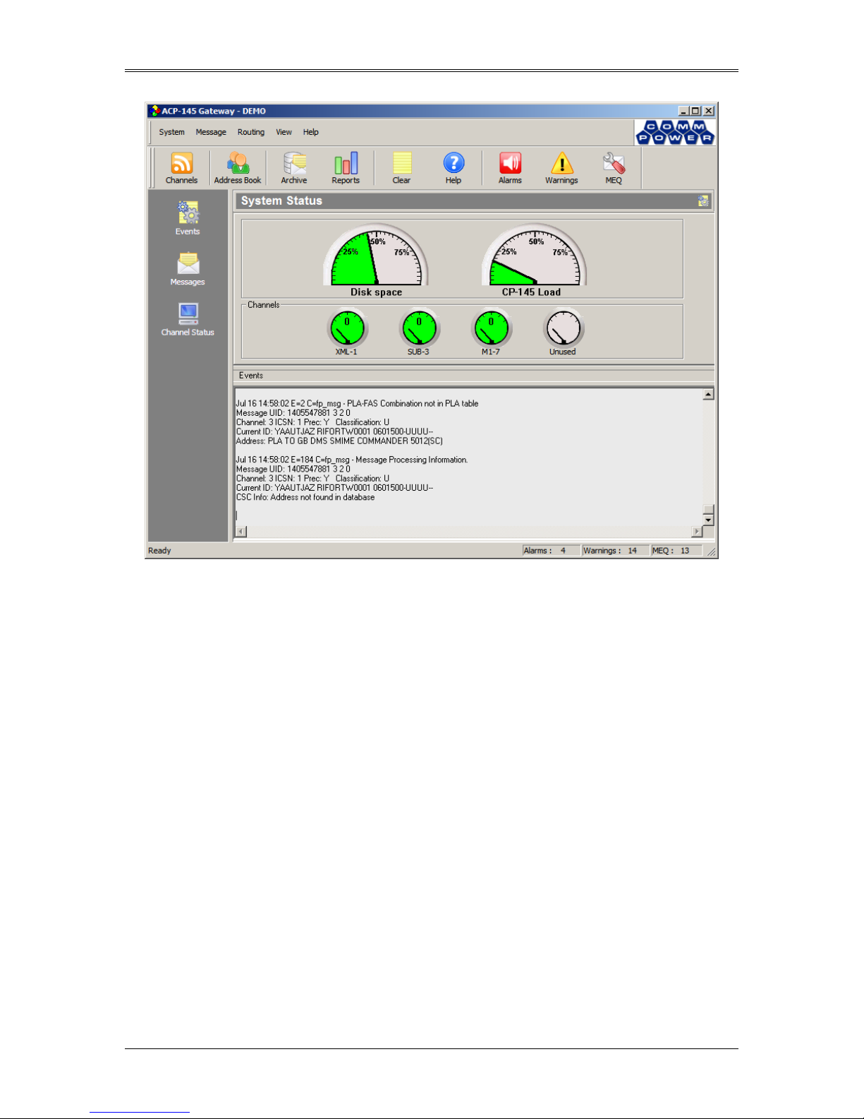
ACP-145 Gateway User's Guide
6.3
TOOL BAR
6.4
CLEAR DISPLAY AREA
This sub-menu option allows the operator to display/remove the Tool Bar.
When the operator select or deselect Tool Bar is selected/deselected from
the View Menu, the Tool Bar is either displayed or removed. When Text is
selected/deselected from the View Menu, descriptive text strings are either
included removed to/from each Tool Bar button.
This sub-menu option enables the operator to remove (or “clear’)
event/message related information from the CP-145 Gateway Main Window
display area. When Clear Display Area is selected from the View Menu (or
you select the Clear button in the Tool Bar), any information currently
displayed in the CP-145 Gateway Main Window display area is removed.
6-2 /cpe/CP-145/usm/004 (07/14)
Page 91
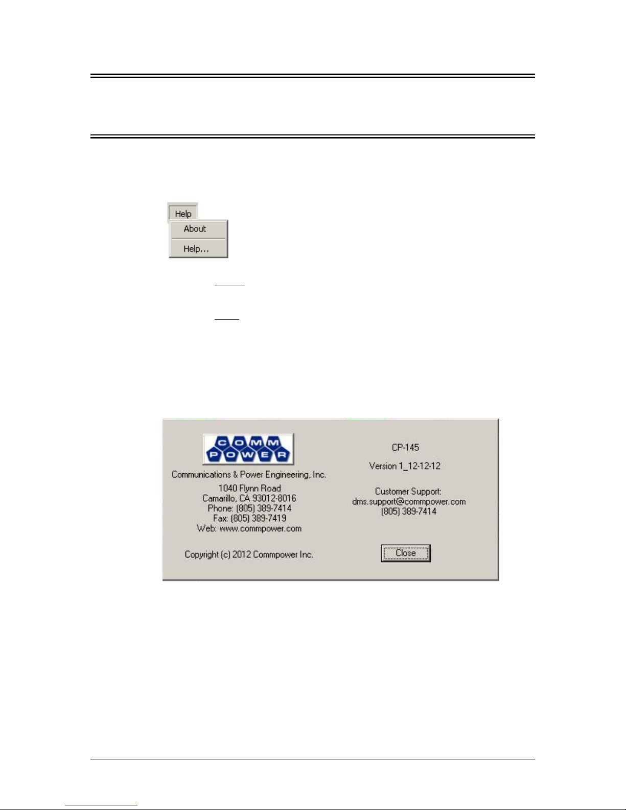
Chapter 7
HELP MENU
7.1
ABOUT
7.2
HELP
This chapter describes the Help Menu. When Help is selected from the
menu bar, a pull-down menu is displayed:
Select About to display company name and CP-145 Gateway
contact/software release information.
Select Help to display the CP-145 Gateway top-level help menu.
This sub-menu option enables the operator to obtain information about
CommPower and the CP-145 Gateway (specifically, company contact and
software release information). When About is selected from the Help Menu,
the About dialog is displayed:
Select the OK button to close this dialog and continue with other CP-145
Gateway operations.
This sub-menu option enables the operator to obtain help information
concerning the CP-145 Gateway. Underlined items in the help window are
text fields that can be used to display specific CP-145 Gateway help text
topics.
/cpe/CP-145/usm/004 (07/14) 7-1
Page 92

ACP-145 Gateway User's Guide
Using the CP-145: This selection will display general information and
startup procedures for the CP-145 Gateway.
System Menu Options: This selection will display information about the
selections in the System Menu.
Message Menu Options: This selection will display information about the
selections in the Message Menu.
Routing Menu Options: This selection will display information about the
selections in the Routing Menu.
View Menu Options: This selection will display information about the
selections in the View Menu.
Help Menu Options: This selection will display information about the
selections in the Help Menu.
Tools and Utilities: This selection will display CP-145 Gateway tools and
utilities.
Event Messages: This selection will display a list of event messages that
may be generated by the CP-145 Gateway.
Troubleshooting/System Tips: This selection will display troubleshooting
tops that can used to recover from problem conditions and some general
tips that can be used to help maintain the CP-145 system.
Report Detail: This selection will display detailed information about the
contents of the System Activity Report, Channel Activity Report, and
Event Log Report.
Glossary of Terms: This selection will display a glossary of terms that
may be used in the CP-145 Gateway documentation.
Select Exit from the File menu to exit the help browser and return to the
CP-145 Gateway User Interface.
7-2 /cpe/CP-145/usm/004 (07/14)
Page 93

Chapter 8
TOOLS AND UTILITIES
8.1
CACHE UTILITY
8.1.1 Cache Utility Startup
This chapter describes the tools and utilities installed with the CP-145 application
software.
Double click CacheUtility.exe in the <install drive>:\cpe\csci\MFG\bin folder
to start the Cache Utility.
Select Clear Logs from the Start>>CommPower CP-145 Gateway >>Tools
menu to start the Clear Logs Tool.
Select Map System from the Start>>CommPower CP-145 Gateway >>Tools
menu to start the Map System Utility.
Select Message Recovery from the Start>>CommPower CP-145 Gateway
>>Tools menu to start the Message Recovery Utility.
Select Queue Monitor from the Start>>CommPower CP-145 Gateway
>>Tools menu to start the Queue Monitor Utility.
This utility provides the administrator (or other user with administrative privileges)
the capability of performing the following CP-145 cache database-related functions:
View information within/from the Security Policy Information File [SPIF], user
name [UN], Security Policy Selection Table [SPST], and Security Policy
Translation Table [SPTT] CP-145 disk-based and memory-based cache databases.
To startup the Cache Utility, perform the following steps:
Via Windows Explorer, navigate to the <install drive>:\cpe\csci\MFG\bin folder.
Find and double-click the CacheUtility.exe file and the CommPower Cache Utility
window is displayed:
NOTE: When the CP-145 is not running, the Cache Utility will start but only the
Cache Database and Disk Object tabs are available. When the CP-145 is running, the
Cache Utility will start with all three tabs available.
/cpe/CP-145/usm/004 (07/14) 8-1
Page 94
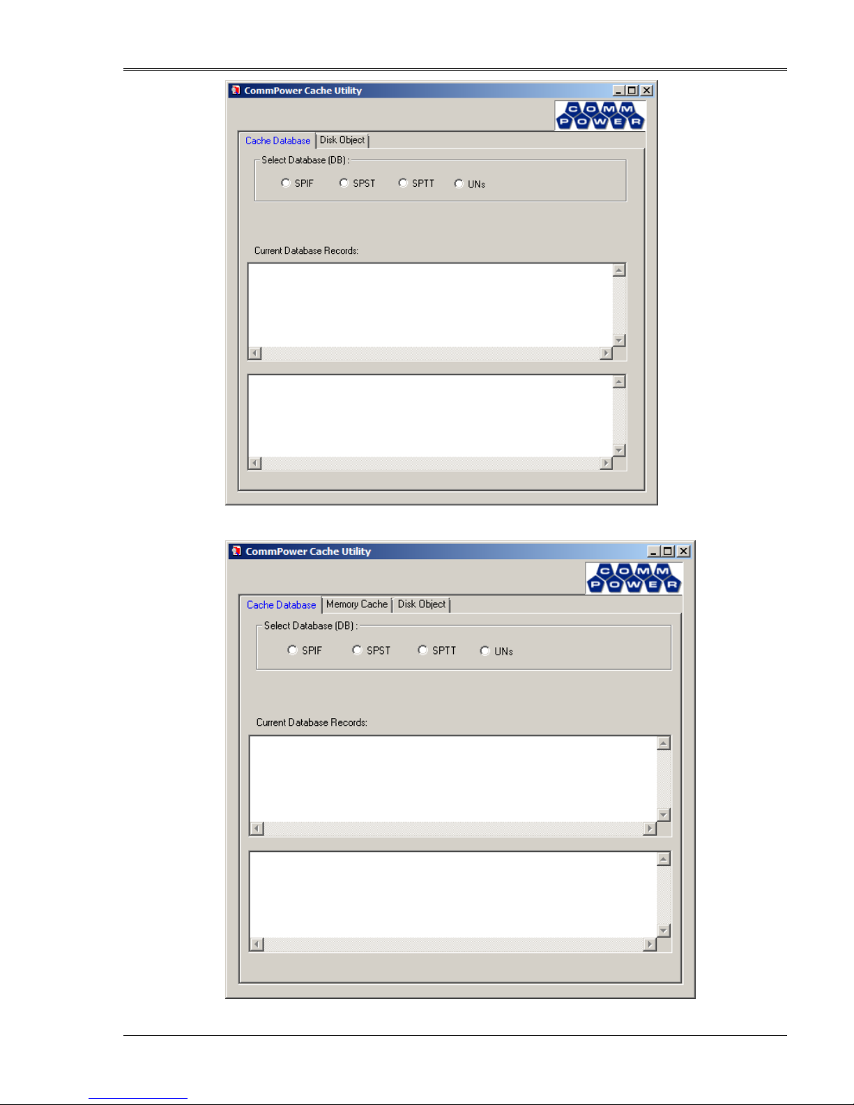
ACP-145 Gateway User's Guide
As shown above, these two tabs are available when the CP-145 is not running.
As shown above, these three tabs are available when the CP-145 is running.
8-2 /cpe/CP-145/usm/004 (07/14)
Page 95

Select one of the following tabs depending on the desired operation:
8.1.2 Cache Utility Operation
8.1.2.1 VIEW CACHE DATABASE
Select the Cache Database tab to view information in the disk-based cache
databases.
Select the Memory Cache tab to view information in the memory-based cache
databases.
NOTE: Information can only be accessed in memory-based cache while the CP-
145 is running.
Select the Disk Object tab to view disk objects and insert the disk objects into
the applicable cache database.
When the Cache Database tab is selected in the Cache Utility main window, the
window is displayed with the buttons and features that enable the administrator to
view information in the disk-based cache databases. Choose the desired cache
database type via one of the following radio buttons:
Chapter 8. Tools and Utilities
Select the UNs button to display all user names stored in the disk-based cache
user name database.
Select the SPIF button to display all SPIFs stored in the disk-based cache SPIF
database.
Select the SPST button to display all SPSTs stored in the disk-based cache SPST
database.
Select the SPTT button to display all SPTTs stored in the cache disk-based SPTT
database.
Upon selecting one the above radio buttons, the requested information is retrieved
from the database and displayed in the top data view pane. Select a DN in the top
Current Database Records pane and information for that DN is displayed in the
bottom pane.
/cpe/CP-145/usm/004 (07/14) 8-3
Page 96
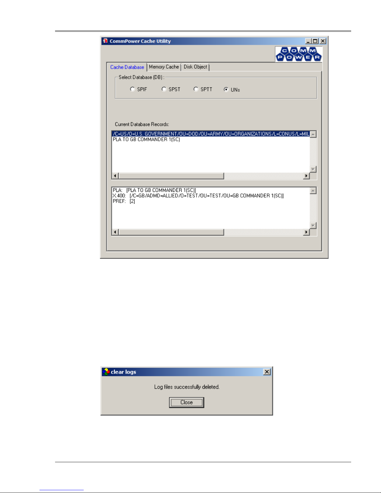
ACP-145 Gateway User's Guide
8.2
CLEAR LOGS TOOL
The Clear Logs Tool provides the operator the ability to manually delete all CP-145
error log files stored on disk. Error logs are stored in the following folders:
<install drive>:\cpe\csci\mfg\logs\ERR
<install drive>:\cpe\csci\mfg\logs\ERR\MSP
To delete the CP-145 error log files select Start>>CommPower CP-145
Gateway>>Tools>>Clear Logs. The following window is displayed when the logs
are cleared:
NOTE: Operator confirmation is not requested when this tool is selected.
The log files are permanently deleted. Check with a system administrator before
selecting this tool.
8-4 /cpe/CP-145/usm/004 (07/14)
Page 97
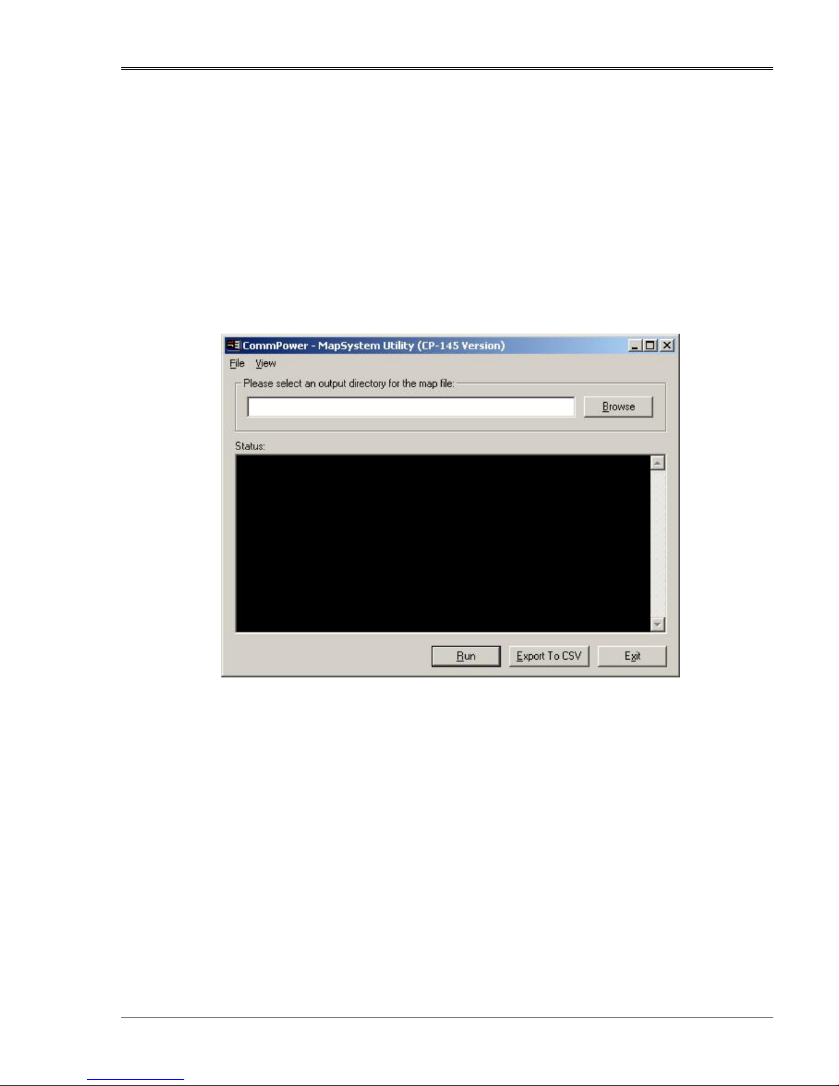
8.3
MAP SYSTEM UTILITY
8.3.1 Map System Utility Startup
The Map System Utility provides the operator with the capability to take a diagnostic
snapshot of all CP-145 configuration settings as well as run simple diagnostic tests.
The utility will then store the collected information and diagnostic test results to file.
The file format can be specified as either text or comma separated (CSV).
The Map System Utility can only be started if the CP-145 is NOT running.
When Start>>CommPower CP-145 Gateway>>Tools>>Map System is selected
while the CP-145 is NOT running the CommPower - MapSystem Utility window is
displayed:
Chapter 8. Tools and Utilities
Map System collects and writes to file the current date and time, all configuration
settings made via the CP-145 Configuration Utility (except Fortezza card\VFC PIN
codes and Message Purge password), all channel configurations made via the user
interface, the CP-145 version, the name of all installed software and the dynamic log
level settings. Also written to the file generated is a list of all installed software, all
Address Lists configured via the Address List Editor and a list of all DNs on each
configured Fortezza card /VFC.
Diagnostic tests performed are:
• Test bind to each configured DSA
• Logon to each configured Fortezza card/VFC
A copy of each error log file in the <install drive>:\cpe\csci\mfg\logs\ERR folder
and a copy of contents in the <install drive>:\cpe\dataxch\uncls\CSWORK folder
are written to a specified location in a folder named Data. The Data folder will be
created by the Map System Utility if it does not exist.
/cpe/CP-145/usm/004 (07/14) 8-5
Page 98
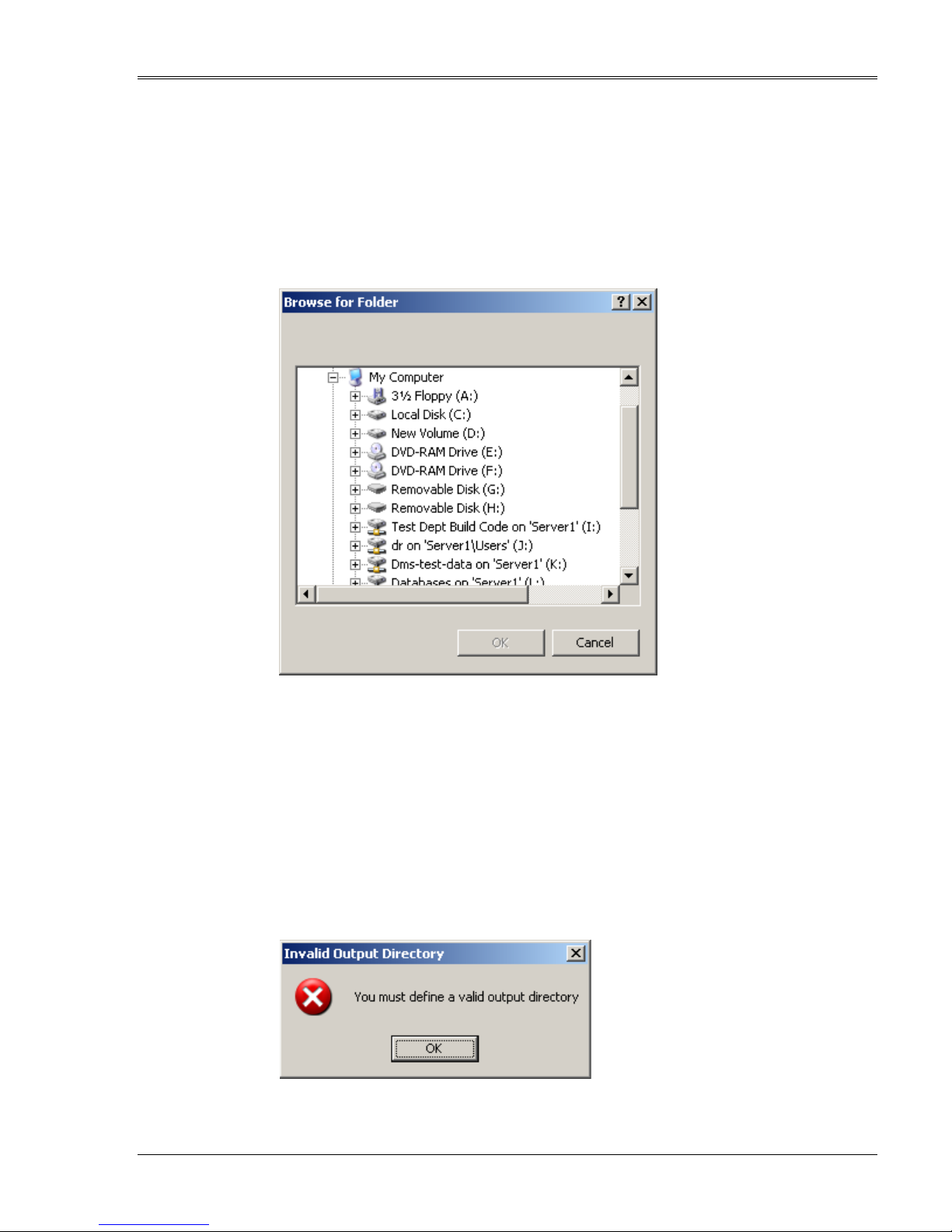
ACP-145 Gateway User's Guide
8.3.2 Map System Utility Operation
All Map System Utility output data is intended to help resolve CP-145 start-up and
messaging issues. The Map System file and the copied log files should be collected
and sent to a CommPower representative when problems with the CP-145 arise.
Once started, the Map System Utility appears as depicted above.
Select the Browse button to set the location of the output file. When the button
is selected the Browse for Folder window is displayed:
Navigate to the required folder and select the OK button. Or select the Cancel
button. Regardless of button selection the Browse for Folder window is closed
and the CommPower - MapSystem Utility window is displayed.
Select the Run button or File>>Run from the File drop down menu to collect
the data and create a text file named MapSystem.txt in the specified folder.
Or
Select the Export to CSV button to collect the data and create a CSV formatted
file named MapSystem.csv in the specified folder.
For either selection, Run or Export to CSV, if an Output Folder was not selected
the following window is displayed:
If an Output folder was selected then the Map System Utility runs. Progress is
displayed in the Status portion of the CommPower - MapSystem Utility
window:
8-6 /cpe/CP-145/usm/004 (07/14)
Page 99
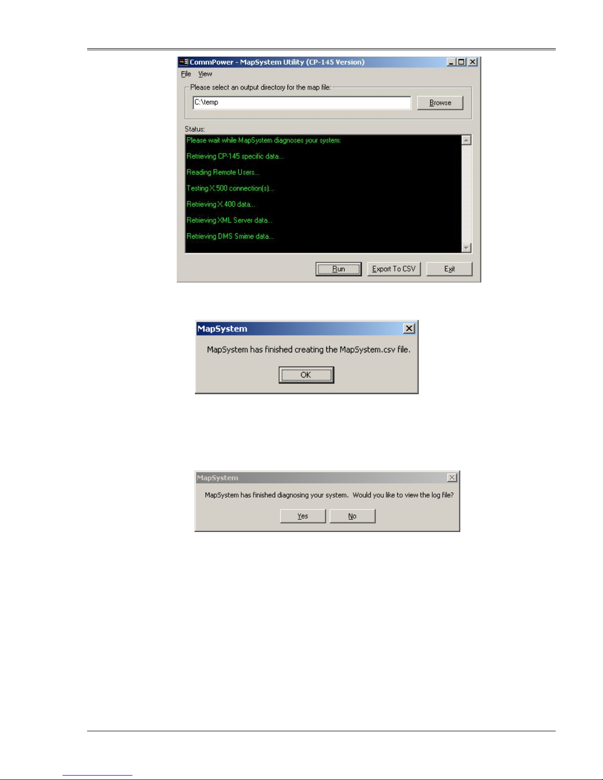
Chapter 8. Tools and Utilities
o If the Export to CSV button was selected the following MapSystem
window is displayed once Map System has completed:
o Select the OK button to close the window.
Or
o If the Run option was selected the following window is displayed once
Map System has completed:
o Select the No button to close this window or the Yes button and the
MapSystem Log File window is displayed:
/cpe/CP-145/usm/004 (07/14) 8-7
Page 100

ACP-145 Gateway User's Guide
8.3.3 Map System Utility Shutdown
8.4
MESSAGE RECOVERY UTILITY
o Use the scroll bar to view information not visible within the view area of
the window.
NOTE: The MapSystem.txt or MapSystem.csv file will be created in
the specified output folder. A Data folder within the specified output folder
will be created by the Map System Utility and contain a copy of all CP-145
error logs and a copy of the CSWORK folder.
To shutdown the Map System Utility, perform the following step:
Select the Exit button on the CommPower - MapSystem Utility window.
Or
Select File>>Exit from the File drop down menu on the CommPower -
MapSystem Utility window.
Or
Select the X in top right corner of the CommPower - MapSystem Utility
window.
If the CP-145 shuts down before fully processing all messages within the application,
these unprocessed messages are marked for recovery within the CP-145 message
archive database. Messages marked for recovery will be automatically re-processed
when the CP-145 is restarted. The Message Recovery Utility provides a user with
administrative privileges the following capabilities that relate to the unprocessed
messages that can exist within an CP-145:
View a list of all messages marked for recovery within CP-145 message
archive database.
Search the list of unprocessed messages for a specific message.
Mark a message in the list for recovery.
8-8 /cpe/CP-145/usm/004 (07/14)
 Loading...