

Page 1
1
Bedienungsanleitung Mover4
Page 2

2
Page 3

3
User Guide Mover4
Version 2016/11 (SW V902-09, HWE 2MV23 HWM V05 DOC V15)
© Commonplace Robotics GmbH, 2011 - 2016
Commonplace Robotics GmbH
Osterfeldstr. 1
D-49326 Melle
Germany
++49 5429 / 374983-4
[email protected]
www.cpr-robots.com
The CE sign confirms that this product meets the
requirements of the directive 2004/108/EC (EMC) and
2002/95/EC (RohS). The according documentation is
deposited at the manufacturer.
Help to save our environment! When reaching the end of
lifetime, do not throw the device into the garbage, but bring
it to a public recycling place.
Page 4

4
Inhalt
1. Safety Instructions............................................................................................................................. 6
2. Introduction ............................................................................................................................................ 7
2.1 Product .............................................................................................................................................. 7
2.2 Specifications ............................................................................................................................... 8
2.3 System Requirements .............................................................................................................. 8
3. Installation .............................................................................................................................................. 9
3.1 Setting up the Robot ................................................................................................................. 9
3.2 Connecting the Power Supply and the USB Adapter ................................................ 9
3.3 Installation of the CPRog Software ................................................................................. 10
3.4 Installation of the Driver for the USB Adapter............................................................ 12
3.5 Licensing ......................................................................................................................................... 13
4. Robot Arm Mover4 ........................................................................................................................... 14
4.1 Geometry ...................................................................................................................................... 14
4.2 Digital Inputs and Outputs ..................................................................................................... 15
4.3 Mounting Flange for the Gripper ........................................................................................ 15
4.4 Drawing of the Robot Base................................................................................................... 16
5. Moving the Robot Arm with CPRog .......................................................................................... 17
5.1 Introduction .................................................................................................................................. 17
5.2 Navigation using the Mouse................................................................................................. 18
5.3 Moving the Robot with Joypad and Buttons ................................................................ 18
5.4 Moving the Robot using the Graphics ............................................................................ 20
5.5 Connect with the Hardware ................................................................................................ 20
5.6 Reset the Zero Points of the Joints................................................................................... 21
6. Programming the Robot Arm with CPRog ............................................................................ 23
Page 5

5
6.1 Program Elements .................................................................................................................... 23
6.2 Recording a Program using the 3D Interface ............................................................. 24
6.3 Saving and Loading of a Program ..................................................................................... 24
6.4 Replay of a Program ............................................................................................................... 24
6.5 Editing a Program with GraphEdit .................................................................................... 25
6.6 Editing a Program with TextEdit ....................................................................................... 25
7. Configuration ..................................................................................................................................... 28
7.1 Application Configuration.................................................................................................... 28
7.2 Robot Configuration ............................................................................................................... 29
8. Interfacing ........................................................................................................................................... 30
8.1 CRI Interface ............................................................................................................................... 30
8.2 ROS – Robot Operating System ......................................................................................... 31
8.3 Direct Access using the CAN Protocol ............................................................................ 31
9. CAN Protocol Specification ......................................................................................................... 32
10. Error Codes ..................................................................................................................................... 33
11. Troubleshooting ................................................................................................................................ 35
11.1 Installation and Program Start ........................................................................................... 35
11.2 Software CPRog ........................................................................................................................ 35
11.3 Hardware Mover4 .................................................................................................................... 36
12. Language Specification ............................................................................................................ 37
Page 6

6
1. Safety Instructions
The Mover4 is designed to be used by adolescents and adults
in edutainment and research areas.
The robot must not be used in industrial production facilities
of in other continuous operation scenarios.
Do not operate the robot when it is unattended.
The gripping area exposes the risk of bruises to the fingers,
especially when using the parallel gripper. Keep off during
operation! The robot must not operate unattended!
The robot must not be used by children without the
supervision by adults. Not suited for children below 3 years.
Small parts pose choking hazards.
Sharp or otherwise dangerous tools or parts must not be
mounted on the robot without according safety measures, e.g.
housings. This especially comprises milling applications or
laser sources.
Take care for a stable stand of the robot.
The robot has been designed for indoor use. They do have to
be protected of humidity, dust or excessive solar radiation.
Do not open the product.
It is necessary to backup important data before the
installation of the CPRog software.
Switch of the power supply when the robot is not in use or
unattended.
Page 7
7
2. Introduction
2.1 Product
The Commonplace Robotics Mover4 is a four axis robot for the use in education,
entertainment and research environments. The robot can lift a payload up to 500 g
with a reach of 500 mm plus gripper.
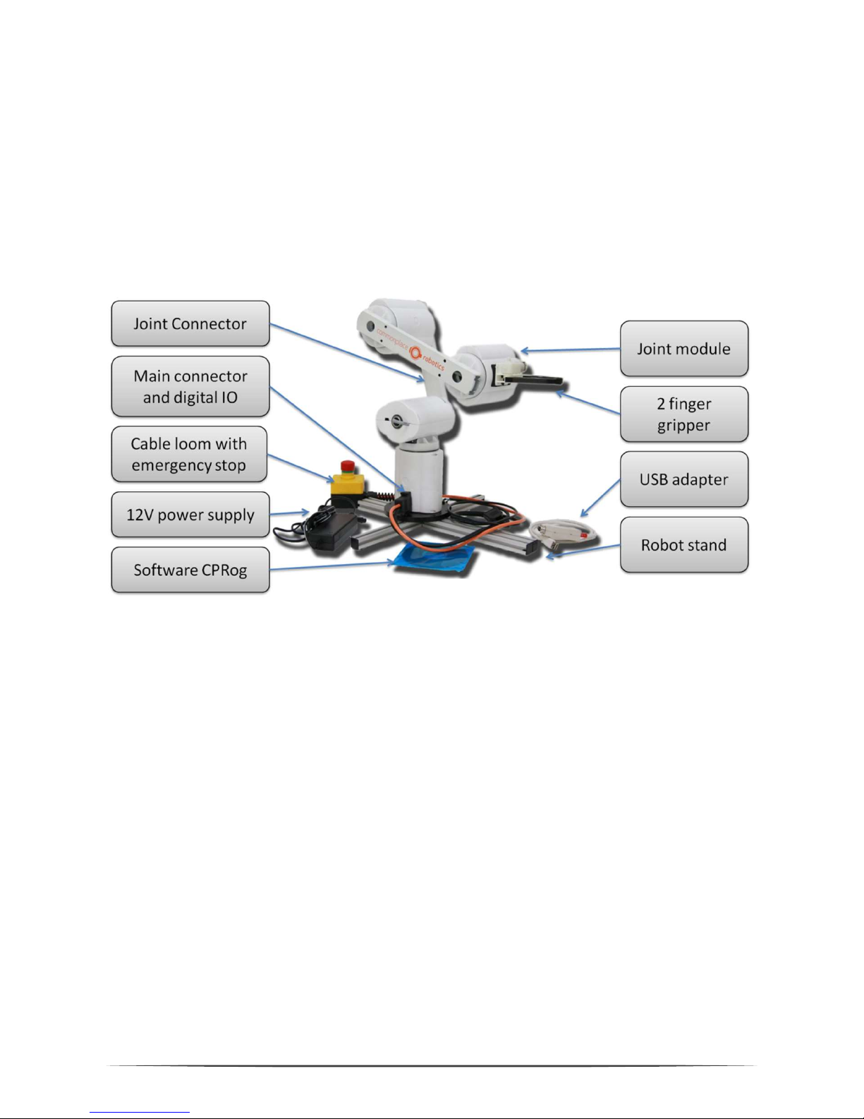
Pic. 1: Mover4 and the necessary components
The modular set up of the robot connects four joint modules with aluminum profiles.
Each joint module contains a servo motor.
The front end of the robot, the flange, allows mounting a gripper or another tool. The
robot base has to be fastened on a stand or a table. At the robot base one plug
connect with power and the PC, another provides digital IO access.
The cable loom is connected with a 12V/5A DC power supply. The USB adapter
connects the control PC with the robots internal communication bus. The CPRog
software allows to control and program the robot.
Page 8
8
2.2 Specifications
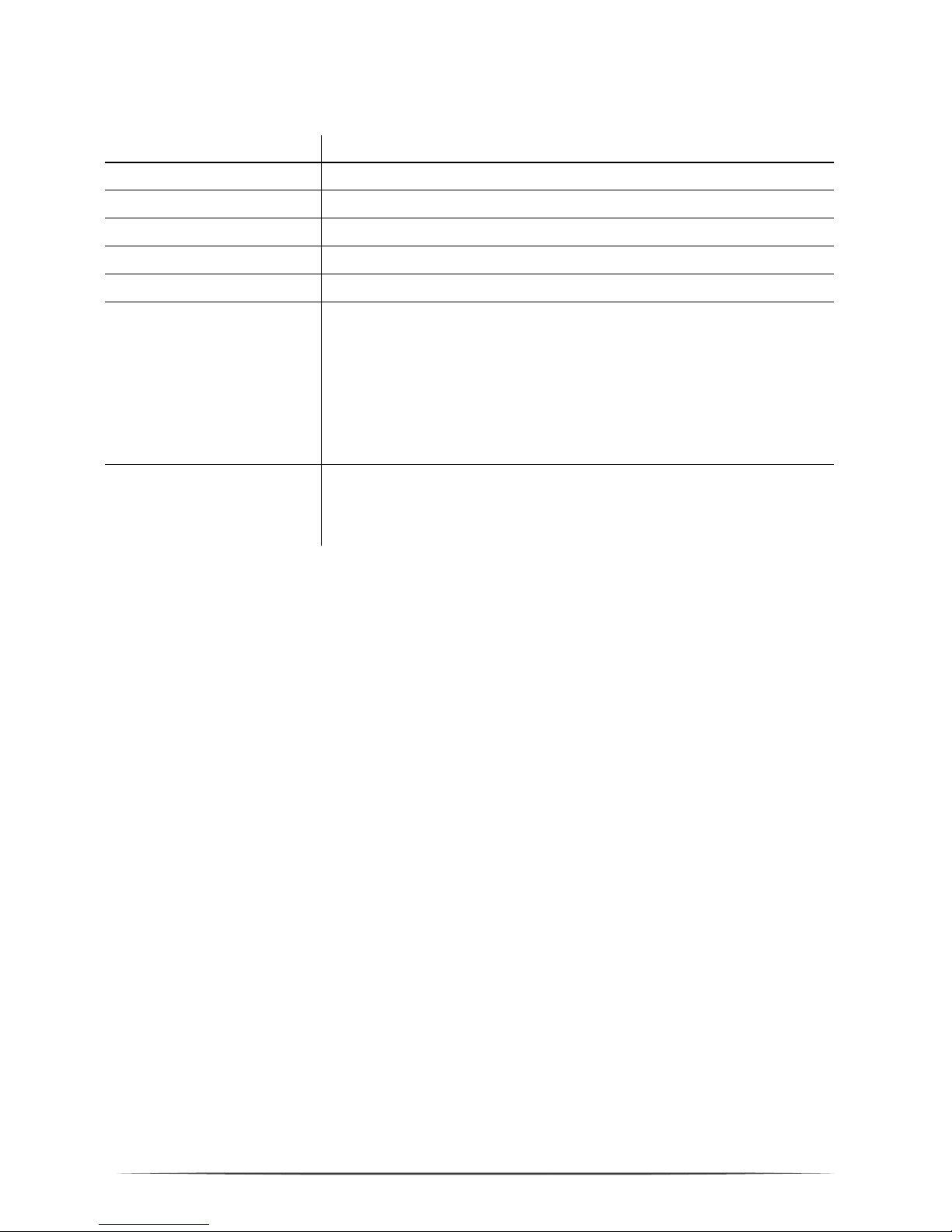
Nr of Joints 4 servo joints
Power Supply 12V DC at max 5 A
Power Consumption Paused: 0,5 A / in motion: < 2.5 A. Fuse with 2.5 A in base
Communication CAN at 500 kBit/s
Reach 455 mm plus gripper
Payload 500 g
Inputs / Outputs At the base:
3 relay out (max. 24V/1A) and 4 digital in (12 to 24V) via DSub 9 poles male.
At the flange:
2 digital Outputs (5V/ 25 mA) und 12V/0,5A supply via
Harting SEK 6 poles.
Communication Definition of position setpoints for all four joints with 20
Hz cycle. Reading of the current position and the motor
current.
2.3 System Requirements
The control the robot with the CPRog programming environment a PC with Windows
operating system is necessary (minimum values):
Operating System: Windows 7 (32 or 64 Bit) or higher.
.NET-Framework 3.5 or higher and DirectX in Version 9.0c
Processor: 1.6-GHz-Pentium
RAM: 1 GB
Up to 50 MB disk space
1 free USB port for the communication with the robot, another one for joypad
operation
Page 9
9
3. Installation
3.1 Setting up the Robot
The robot has to be placed on a table or stand so that he cannot tumble down.
3.2 Connecting the Power Supply and the USB Adapter
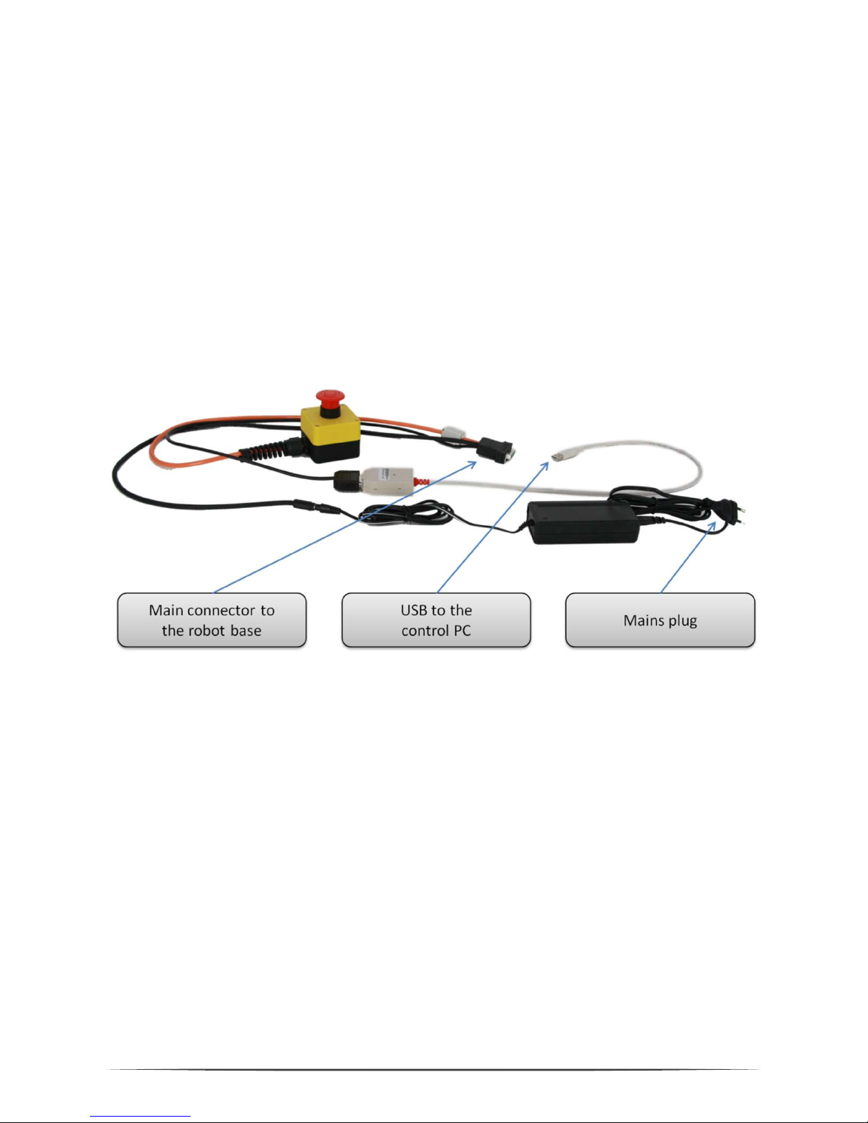
Pic. 2:
Cable loom and USB a
dapter
The cable loom connects the power supply, the USB adapter and the robot as
depicted above. All connectors fit only one way. The USB adapter may be white or
black, depending on the current type.
When plugging in the USB2CAN adapter, a driver installation assistant may appear.
Please refer to section 3.4 for installation guidelines.
Page 10
10
3.3 Installation of the CPRog Software
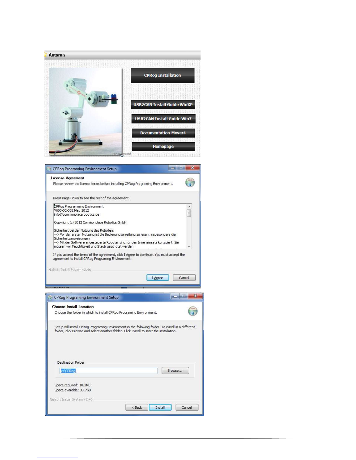
Insert the CPRog CD into the drive
.
Depending on your systems
configuration the CD menu will open
automatically, or you have to start it
manually:
D:\.autorun\autorun.exe
Choose the first button „CPRog
Installation”
Maybe you have to all
ow changes to
be made on your system.
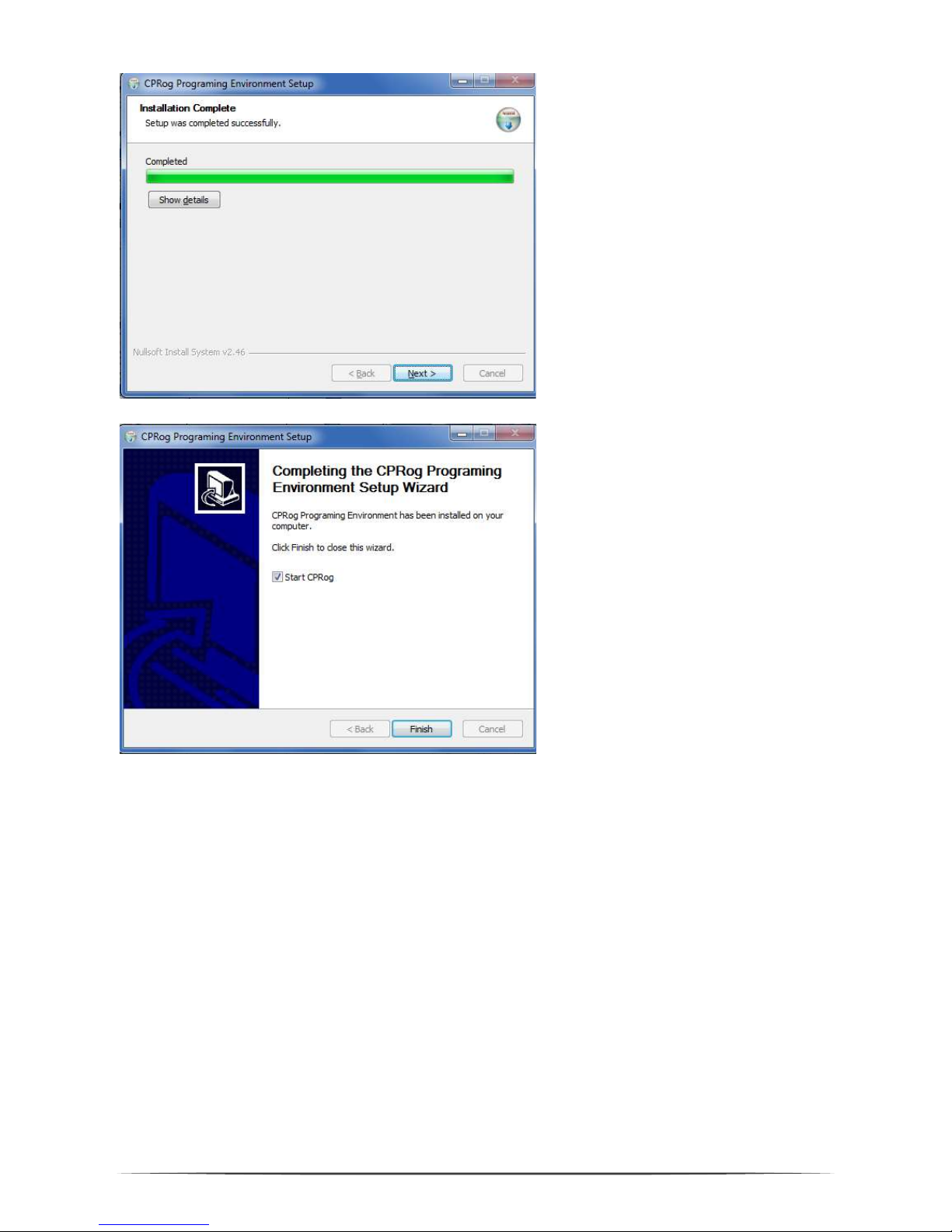
After the installer has started you
need to choose between English
and German as language.
Then you need to confirm the
license agreement.
In the next step y
ou ca
n choose
where to install CPRog. The
recommended directory is
c:\CPRog.
When installing in a Windows
program directory like
c:\Programme it is possible that
CPRog can only be started as
administrator.
Page 11
11
The installation normally takes o
nly
a few seconds.
The installer checks, if DirectX 9.5 is
installed. If not it will install theses
libraries from the CD or via
download. This will take some
minutes.
The installation of DirectX 9.5 is
necessary even if e.g. DirectX 11 is
already installed.
When f
inishing the installation y
ou
can choose to directly start CPRog.
Now you can start CPRog using the link on the desktop or via the start menu.
Installation Failure: The installation assistant checks, if all necessary extensions
are available, especially the .NET-Framework and DirectX 9.5. If this is not the case
an error message will appear. DirectX is installed automatically, but the .NETFramework has to be installed manually:
Search in the net for “Microsoft .NET download” and install
Page 12
12
3.4 Installation of the Driver for the USB Adapter
The robot is delivered with the PCAN USB driver from www.peak-system.com. To
run the adapter the according driver has to be installed. This can be done from the
CPRog installation CD (button “Install USB-CAN adapter”), or using the
manufacturers installation CD.
After starting the installation you need to
accept the license agreement and
set the installation folder.
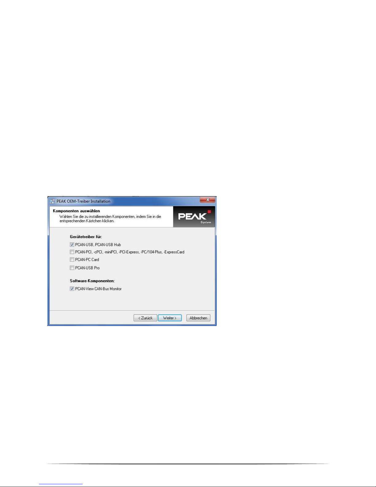
In the next step please check the PCAN-USB device and the PCAN-View CAN-Bus
Monitor as shown on the following picture for installation.
Choose for installation:
PCAN-USB
PCAN-View
The PCAN-View monitor allows to check if the adapter is connected correctly.
Page 13

13
3.5 Licensing
The CPRog software needs a license key to start. This key is in most cases already
integrated into the installation version of CPRog. Nothing has to be done.
If it is not, e.g . because you have installed a demo version, please see the following
information. The key, an XML file, has to be stored in the directory
\CPRog\Data\License
The CPRog installer copies the key Demo.xml to the directory. With this key CPRog
starts in demo mode. The runtime is limited to 10 minutes; afterwards you need to
restart CPRog.
When you do need a license key, please send a short mail with the following
information to [email protected]:
Your Name or the name of the responsible contact person
Your companies / organizations name
We will send you your key via mail. After starting CPRog your licensing data are
shown in the main frame and can be shown complete with the
Programbutton/License.
Please do not change the content of the license file, this will render it invalid!
A standard license allows the installation and use of CPRog on an arbitrary number
of computers in the company or organization of the license holder.
Page 14
14
4. Robot Arm Mover4
4.1 Geometry
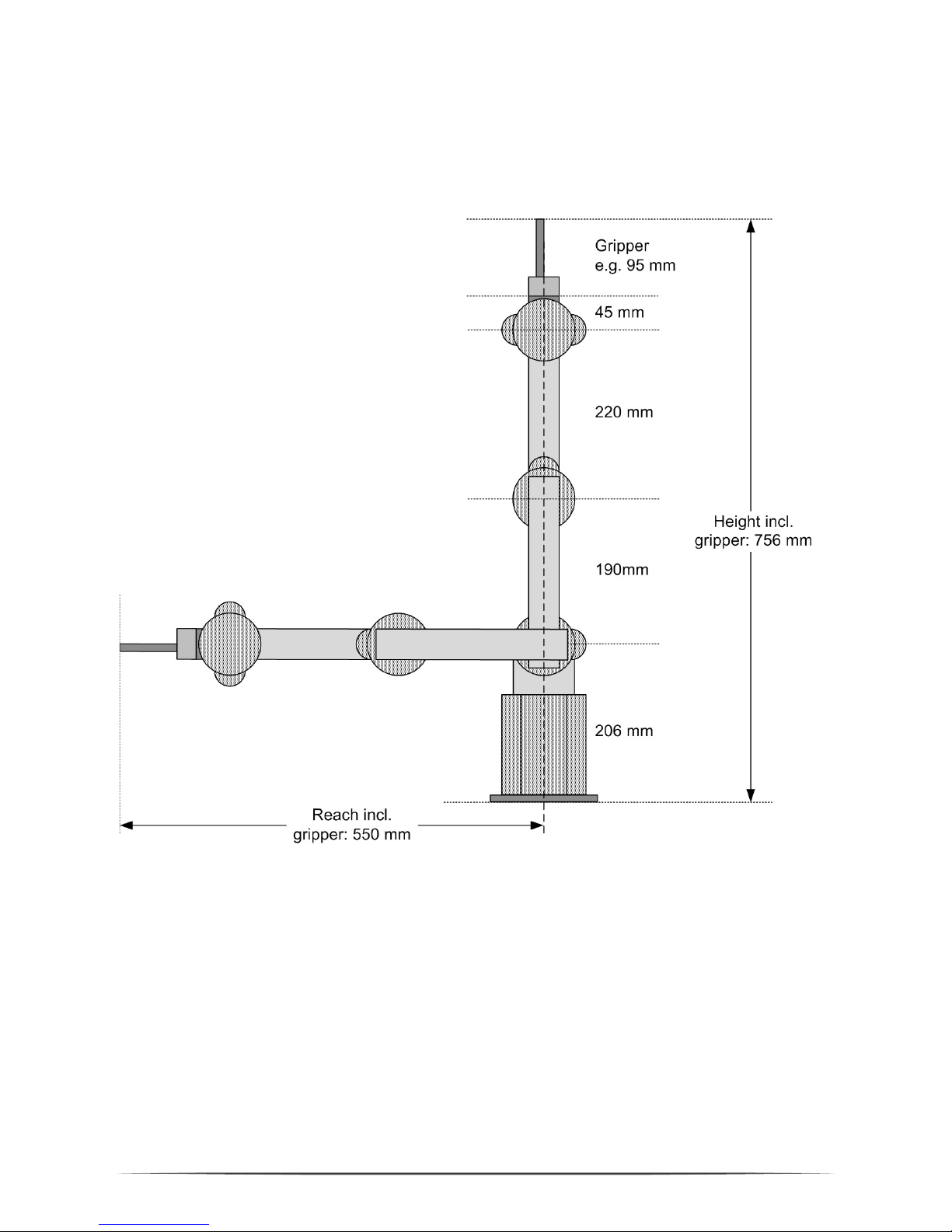
Pic. 3: Mover4 simplified side view
The picture shows the joints length of the Mover4 robot arm. Including the gripper
the arm reaches 550 mm.
CPRog offers functionalities to limit the workspace, see section 7.2.
Page 15
15
4.2 Digital Inputs and Outputs
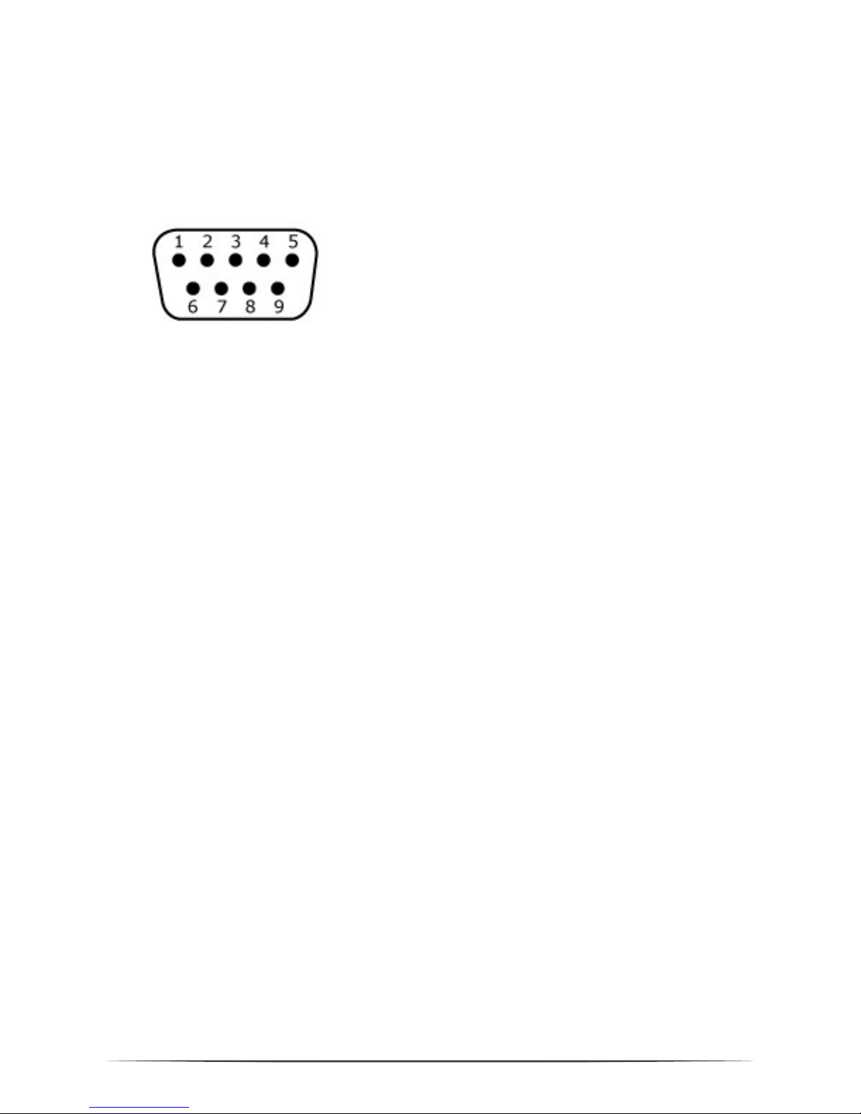
The robot base shows a D-Sub plug with several digital inputs and outputs. The pin
assignment is shown below.
D-Sub Male: View from the
front on the pins.
24V DIO, D-Sub Male
Pin 1: Out1 24V
Pin 2: Out2 24V
Pin 3: Out3 24V
Pin 4: In1
Pin 5: In2
Pin 6: In3
Pin 7: In4
Pin 8: GND
Pin 9: 24V Supply
Pic. 4: Pin assignment at the base digital IO plug
The 24V-DIO-Board provides relays and 12 to 24V digital inputs, allowing to
communicate with a PLC on 24V level. The outputs are able to provide 1A each,
forwarding the external supply voltage from pin 9. The inputs are 12 to 24V.
Two further digital outputs with TTL-Level can be found on the flange of the robot,
see the next section.
4.3 Mounting Flange for the Gripper
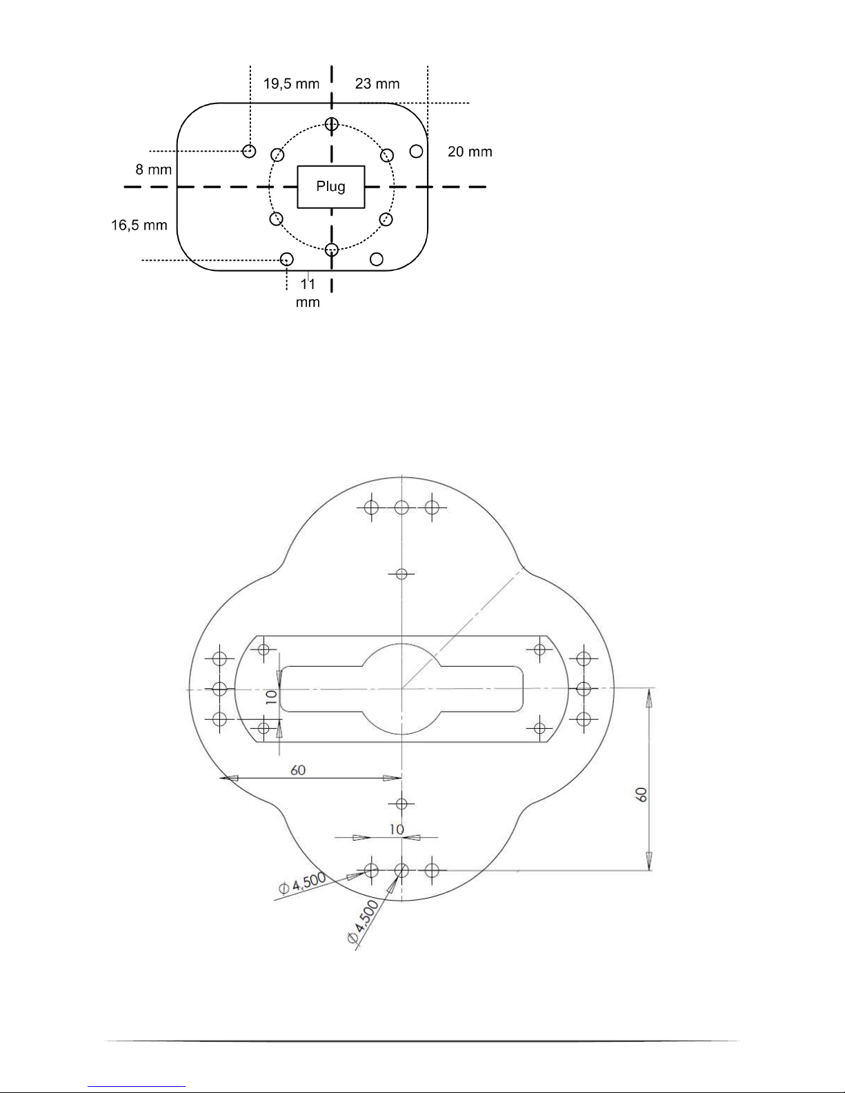
The robot flange offers 10 M3 threads to connect gripper or other devices. A plug
allows electrical connectivity.
Six of the threads are placed on a 15 mm reference circle; the remaining 4 M3
threads are located as shown in the drawing. The plug is a Harting product SEK male
6 poles:
Page 16
16
Pin1: 12V, max 0.5A
Pin2 GND
Pin3: DOut 11 (5V TTL)
Pin4: DOut 12 (5V TTL)
Pin5: not connected
Pin 6: not connected
Pic. 5: Drawing of the flange
4.4 Drawing of the Robot Base
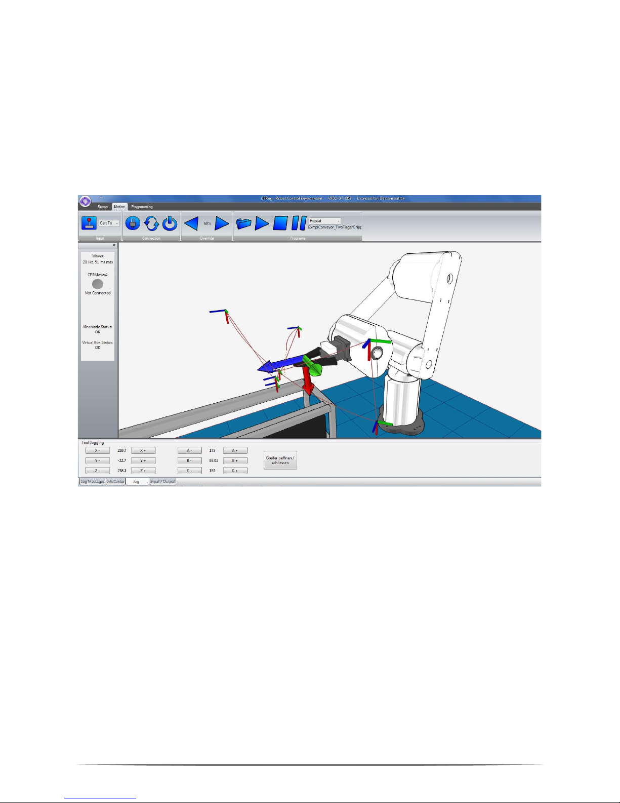
The robot can be mounted using the M4 through holes.
Pic. 6:
Drawing of the robot b
ase plate
Page 17
17
5. Moving the Robot Arm with CPRog
5.1 Introduction
The CPRog programming environment allows to control and program the Mover
robot. Both online and offline working is possible.
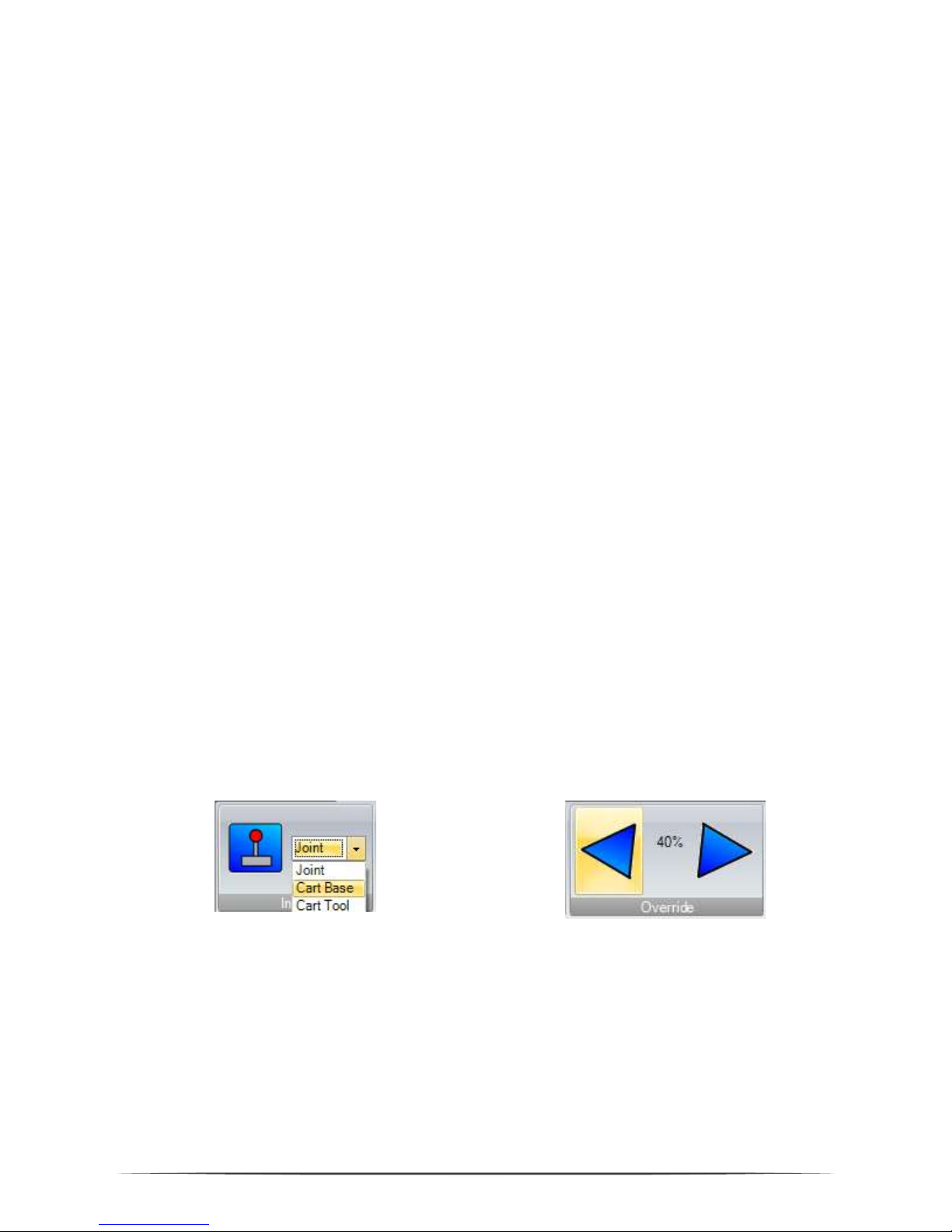
Pic. 7:
CPRog
User Interface
In the upper area the three ribbons “Scene”, “Motion” and “Programming” provide
access to the main functionalities.
On the left corner information on the robots current state are provided.
On the lower side four sections are found:
„Log Message“: Messages regarding the programs state
„Info Center“: Shows joint values, the Cartesian position and the motor
currents
„Jog“: Buttons to move the robot
„Input / Output“: View and set digital IOs
Page 18
18
5.2 Navigation using the Mouse
A 3 button mouse is recommended to navigate in the CPRog 3D environment:
Left button: Selection of robots and other objects
Middle button: Navigation in the scene
o Rotate: drag the mouse while holding the middle button
o Pan: drag the mouse while holding the middle button and pressing
down the CTRL-key
o Zoom: Drag the mouse while holding the middle button and pressing
down the SHIFT-key (zooms to the center of the scene), or turn the
mouse wheel (zooms to the current cursor position)
Right button: Opens the context menu
Alternatively the function of the left mouse button can be changed in the upper
menu area at Scene/Navigation. Possibilities are Selection, Rotation, Panning or
Zooming.
5.3 Moving the Robot with Joypad and Buttons
The robot can be moved (or “jogged”) manually, as long as no program is running. The
main elements are the button to connect the joypad, the combobox to choose the
motion type and the override.
Pic. 8:
Elements to jog the robot
When pressing the joystick button CPRog connects with a joypad. Nevertheless,
CPRog tries to connect on start up. When the connection succeeded a green ok sign
is shown on the joystick button.
The device must have the type “Joystick” or “Gamepad”. Further information on the
connection trial is provided in the log window.
Page 19
19
The „Joint“ mode allows to turn the single robot axis from A1 to A4. In “Cartesian”
mode the robot moves in straight lines following the x, y and z coordinate axis. The
rotation is defined with the B commands. In „Cartesian Tool” mode the robot moves
aligned to the current tool coordinate system.
The override scales the motion speed between 0 and 100%.
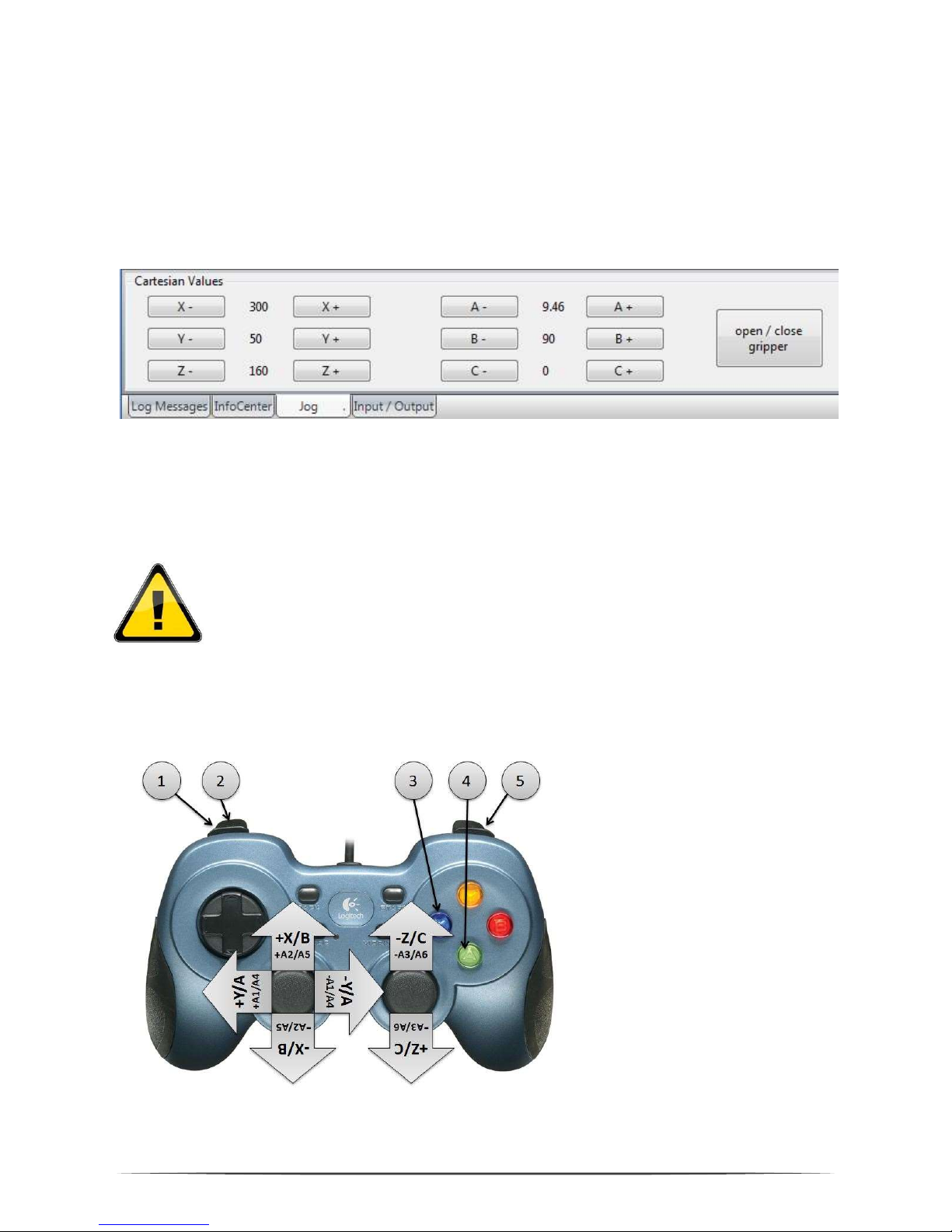
Pic. 9: Buttons to jog the robot in Cartesian mode. In joint mode the buttons change to the axis A1 to A4.
While jogging in Cartesian mode virtual walls can be switched on to limit the motion
and thereby avoiding e.g. collisions. See section 7 for details.
When the virtual walls are active the robot blocks further motions when
leaving the allowed area. These restrictions do not hold in joint mode.
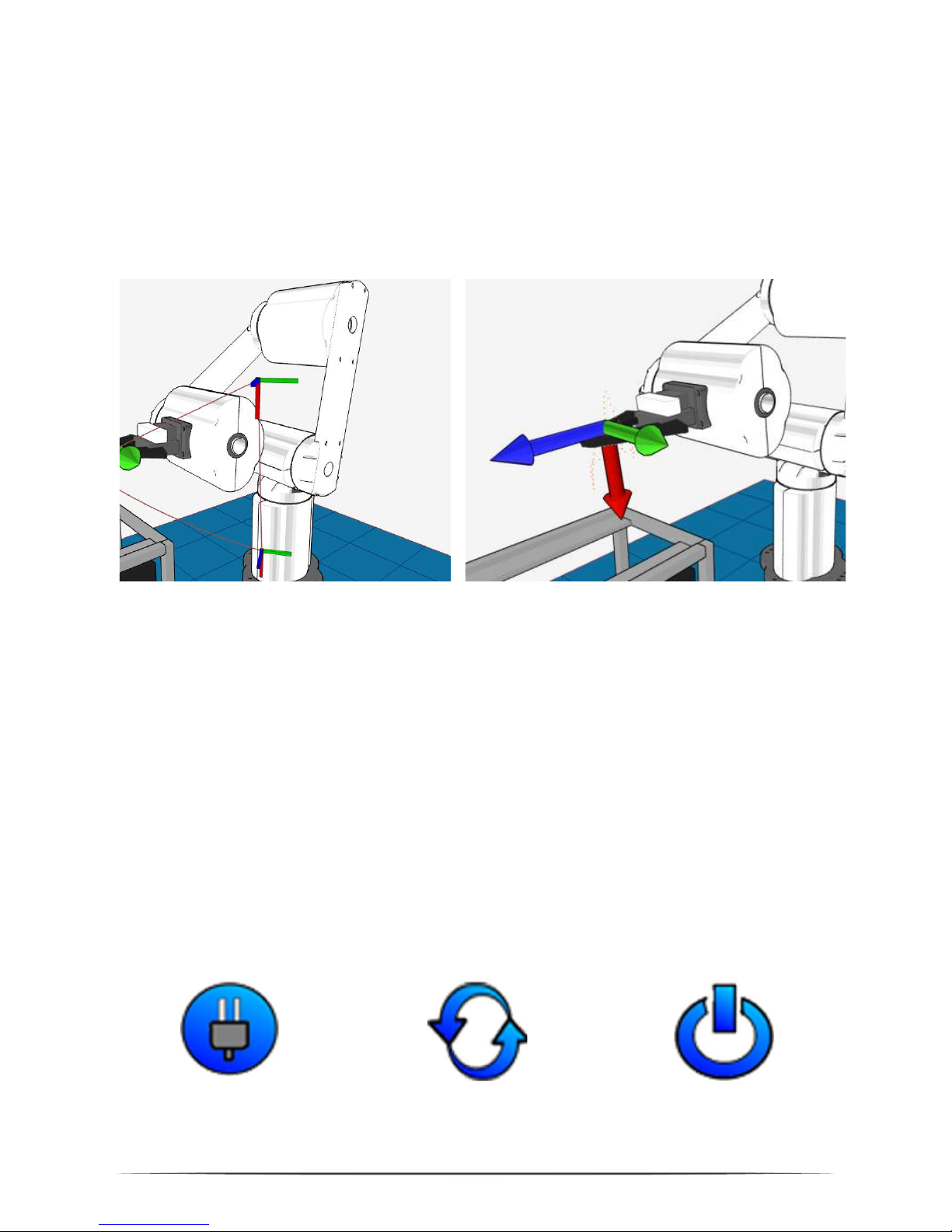
The most convenient way to move the robot is with a connected joypad, the picture
below shows the assignment of keys.
Reference:
1. Change motion mode
2. Change active robot
3. Open / close gripper
4. Record a motion point
5. Change button
assignment:
when pressed it is not
+X, but +B
Pic. 10: Assignment of keys for the joypad. Upper markings for Cartesian mode, lower for joint mode.
Page 20
20
5.4 Moving the Robot using the Graphics
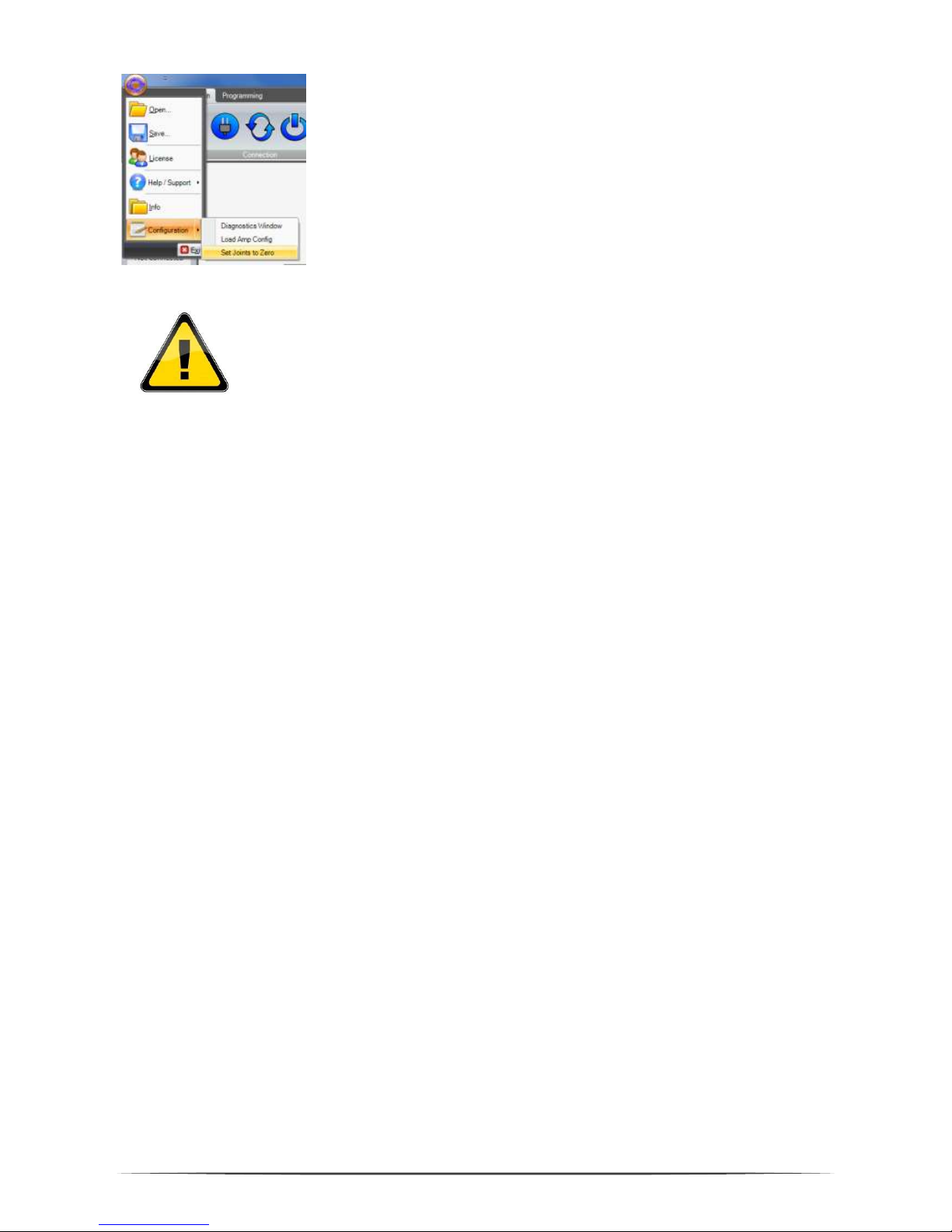
An alternative to the joypad is to drag the robot in the graphical 3D environment.
When selecting a joint of the robot with the left mouse button, the joint outlines
blink red. When selecting the joint and moving the mouse with pressed left mouse
button this joint will rotate forward or backward, depending on the mouse motion.
Pic. 10: Joint and coordinate system outlines after selecting with the mouse.
The motions are possible in simulation and with the real robot. They are also scaled
with the override buttons.
5.5 Connect with the Hardware
The real robot can be controlled in the same way as the simulated one, only the
hardware has to be connected before: connect, reset errors and enable motors.
Prerequisites are that the robot is connected via the USB-CAN adapter and the
robots supply is running (plugged in, switched on and emergency button released).
Pic. 11:
Buttons to connect to t
he hardware, reset the errors and enable the motors
Page 21

21
Step 1: Connect with the hardware. This step initializes the USB-CAN
interface.
The LED on the left side of CPRog changes color from grey to red.
Below the LED several error messages are displayed.
Step 2: Reset the errors. This button resets the error memory of the joint
module controller in the robot. The joint values are copied from the
real robot to the simulation environment.
The 3D visualization of the robot has to match the current pose
of the real robot now. This has to be verified every time the
errors are reset!
The LED stays red. The error messages get cleared, only “Motors
not enabled“ is remaining.
If further error messages remain visible try again and see section
11.3 for possible approaches.
Step 3: Enable the motors. Now the robot can be jogged as described
above.
The LED is green now.
5.6 Reset the Zero Points of the Joints
The joint modules of the Mover4 store the last joint value in their memory, so the
robot is aware of his current position after being switched on. But if these values are
not correct, the joints need to be calibrated. Reasons may be:
Turning the joints while the robot is without power supply
Stopping the robot with the emergency stop during a motion
…
To calibrate the robot it has to be jogged into a perpendicular position using the joint
mode. The sticker on the axis provide assistance, their triangles should be aligned
with the structures marks.
Page 22
22
When the robot is in the correct position press
“LogoCircle/Configuration/SetJointsToZero” in the upper
left menu. Confirm the following dialog with „OK“.
This function takes back the motor enabling, so the error
reset and enable motor buttons have to be pressed.
The precision of the calibration is vital for replaying old
programs. If theses old programs (recorded before the
calibration) show precise motions close to the environment
they have to be replayed slowly the first time. It may be
necessary to re-teach positions.
Page 23

23
6. Programming the Robot Arm with CPRog
6.1 Program Elements
A Mover4 robot program is build out of the following commands:
Lin The robot moves on a straight line from the
current position to the target position. The
velocity is defined in mm/s.
Joint Interpolates the axis from the current position to
the target position in joint coordinates. Velocity
is defined as percentage of the maximum joint
rotational velocity.
Relative A linear or joint motion with a defined distance
starting at the current position. Velocity in mm/s
or percent.
Wait
Waits for a time span defined in s.
Gripper The gripper command open (100%) or closes
(0%) the gripper.
DigitalOut Sets a digital output. The button on the left side
records the current gripper state.
Loop Iterates the included commands until a digital
input is set or the defined number of iterations is
reached.
If-Then-Else Executes two different command lines
depending on the state of a digital input.
ExternalMotion Passes control to an external program connected
via sockets, e.g. a vision system. See section
Fehler! Verweisquelle konnte nicht gefunden
werden. for details.
Sub Allows to call sub programs to structure longer
tasks.
Page 24
24
The complete language specification is found in section Fehler! Verweisquelle
konnte nicht gefunden werden. .
6.2 Recording a Program using the 3D Interface
Using the 3D screen a program can be recorded using the joypad or the buttons.
Joypad: Every time the A button (or button 2) on the joypad is pressed a linear
command to the current robot position is recorded. If necessary a command to open
or close the gripper is added, together with a short break. A sound indicates that the
point was recorded.
Program Buttons: If there are still commands in the memory, they can be deleted
using the Delete button. Afterwards linear, joint, gripper and break commands can
be recorded. The buttons record the current state of the robot or gripper.
Pic. 12:
Buttons
for program generation
6.3 Saving and Loading of a Program
With the button „Save Program” the commands are saved in an XML file in the
directory
c:\CPRog\Data\Programs\
or in any other user defined folder. The button to load a program is found in the
Motion/Programs area.
6.4 Replay of a Program
Page 25
25
The buttons in the area Motion/Programs allow to replay, pause and stop a program.
The replay can be done in single, repeat or step mode.
6.5 Editing a Program with GraphEdit
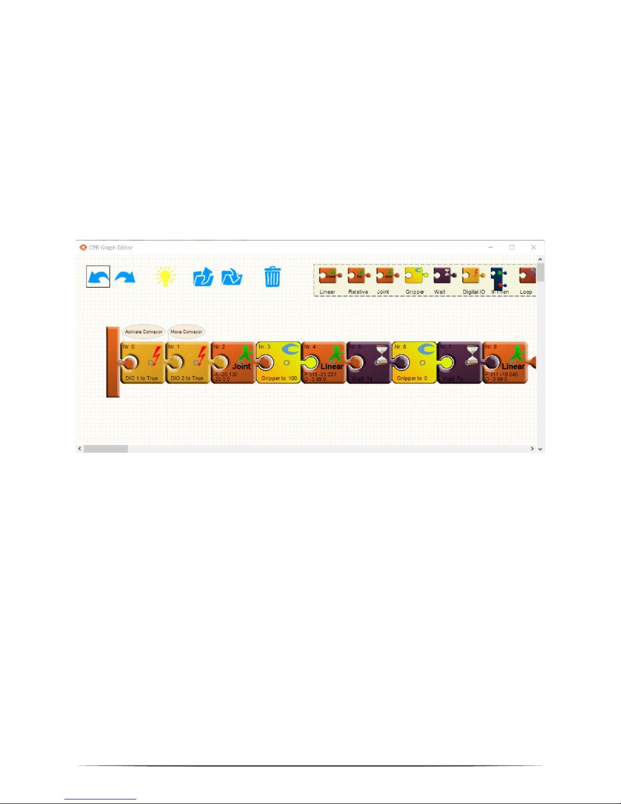
The button Programming/Editor opens a graphical program editor. This editor
allows in a puzzle visualization to adapt and create programs.
Pic. 13:
Graphical program editor
In the upper left area common elements are found, Undo/Redo and Load/Save. Two
further buttons need explanation:
The dust bin deletes the selected puzzle piece
The light bulb updates the program on the current robot to the updated
version. It also saves the program.
New commands can be dragged from the shelf on the upper right corner. They are
initialized with the current robot position.
Commands can be copied by dragging them with the CTRL key pressed.
6.6 Editing a Program with TextEdit
Page 26
26
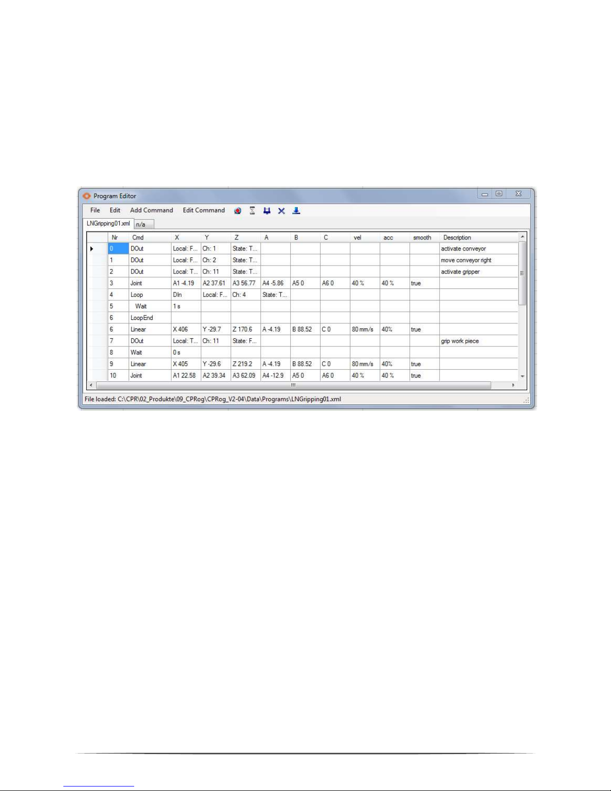
Using the button beneath GraphEdit opens the TextEdit Program editor. This editor
is more usable for bigger programs and provides more information.
The editor contains a syntax check. Illegal cells are marked red, the syntax for the
command is shown in the bottom line as an assistance.
When there are errors in the program it cannot be saved.
Pic. 14: TextEdit program editor
The five picture buttons allow direct interaction:
Recording a motion command (lin or joint according to the robots current
motion type) with the current robot position
Recording a break
Recording a gripper command
Deleting the selected line
Setting the selected line as starting point for the next program start
All fields of the commands can be edited directly to e.g. change the velocity.
Changes are accepted when clicking on another line or field. A line can be copied
with Ctrl-C (or in the Edit menu), Ctrl-V pastes the command again.
All new commands are inserted in the line above the selected line.
Page 27

27
When choosing ‘Save’ from the File menu the current program is written and loaded
by the robot. So the robot is again in synch with the text editor.
When choosing ‘Save As’ from the File menu the current program is saved under a
different name. The new file is loaded by the robot.
Page 28

28
7. Configuration
7.1 Application Configuration
The application configuration can be done by adapting the parameters in different
XML files.
7.1.1
Startup Configuration
The file c:\CPRog\CPRFrontend.xml allows to set the language and the start project.
<Program Language="DE"/> Possible choices are DE and EN.
<StartUp Project="..\..\Data\Projects\Mover4Basic.prj" />
7.1.2
Project File
The project file can be found in c:\CPRog\Data\Projects\
The initial position of the view camera is defined in the line:
<Camera xPos="683" yPos="826" zPos="306" yRot="-10.1" zRot="-161"/>
Offset and Tool of the robot can be changed:
<Robot Name="Mover" Type="CPRMover4" Homepos="-5.0 10.0 130.0 -70.0 0.0 0.0"
OffsetX="0.0" OffsetY="0.0" OffsetZ ="0.0" OffsetRX="0.0" OffsetRY="0.0"
OffsetRZ="0.0" Parent="-1" Tool="TwoFingerGripper.xml"/>
Objects in the Virtual Environment can be added, static or active:
<ActivePeripheral Name="Conveyor" Gravity="false" Sensable="false"
Geometry="LN_Conveyor.obj" OffsetX="535" OffsetY="-26" OffsetZ ="0" OffsetRX="0"
OffsetRY="0" OffsetRZ="180" GeometryPlatform="LN_ConveyorPlatform.obj"
OffsetPlattformX="-240.0" OffsetPlattformY="0.0" OffsetPlattformZ="175.0"
TravelX="445.0" TravelY="0.0" TravelZ="0.0"/>
<StaticSceneObject Name="WorkPiece" Gravity="true" Sensable="false"
Geometry="LN_Workpiece.obj" OffsetX="780" OffsetY="-26" OffsetZ ="240"
OffsetRX="0" OffsetRY="0" OffsetRZ="0.0"/>
Please refer to the examples to get to know different combinations. The CAD files
have to be in .stl (only ASCII) or AliasWavefront .obj format, units are mm.
Page 29

29
7.2 Robot Configuration
For each robot in the CPRog simulation a XML config file exists, e.g.
C:\CPRog\Data\Robots\CPRMover4\CPRMover4.xml
Definition for the velocities in Jog mode:
<Velocities JogCart="200.0" JogOri="45.0" JogJoint="1.0"/>
A virtual cell can be defined as a safety space the robot cannot leave in Cartesian
mode:
<VirtualBox active="false" xMin="50.0" xMax="400.0" yMin="-150.0" yMax="250.0"
zMin="10.0" zMax="300.0" />
The cell walls are not active in joint mode.
Also the control parameter of the joint controller can be adapted, e.g. the position
and velocity PID settings. This can be done with the button „Load Amp Config” in the
program start menu. This button reads a parameter file and transfers the data to the
connected robot arm.
Further information on the joint controller and the CAN protocol can be found in the
servo controller documentation.
Get in touch with CPR to get this documentation: [email protected]
Changing the joint controller configuration requires knowledge of
the system. The robot may move in unexpected ways if ill-fitted
parameters are uploaded. The robot may damage itself and its
environment. Any warranty is void when uploading parameter files
not generated by CPR!
Page 30
30
8. Interfacing
8.1 CRI Interface
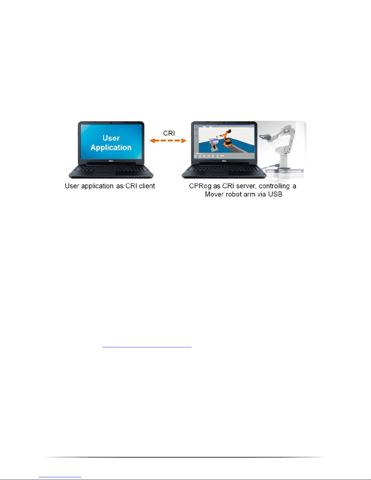
The CRI interface allows to connect via Ethernet and jog the robot, send motion
commands and start programs.
With this setup you can use the CPRog functionalities and implement custom
algorithms in a CRI client, e.g. a vision system. Possiblities then are e.g.:
Send a list of motion or digital out commands to the robot and then start
the assembled program.
Jog the robot arm by sending jog values.
Motion are possible in joint or Cartesian space.
The CRI documentation and an example CRI client written in C# can be downloaded
on our Wiki in the Interfacing section:
http://wiki.cpr-robots.com
Page 31

31
8.2 ROS – Robot Operating System
The Willow Garage Robot Operating System (see www.ros.org) is wide spread in the
research community, especially when dealing with service robots. For the Mover4
packages are available to connect with the hardware and to command the robot by
joint and position messages. A RViz plugin and a moveIt interface are available.
The packages can be downloaded at
https://www.github.com/CPR-Robots
8.3 Direct Access using the CAN Protocol
It is also possible to directly access the Mover4 on CAN field bus level, using a
custom control software. The necessary protocol specification is found in the
following section.
Code examples can be found on the Wiki in the Interfacing section:
http://wiki.cpr-robots.com
Page 32

32
9. CAN Protocol Specification
The Mover4 uses the CPR-CAN protocol, a custom CAN protocol with 16 bit position
data width.
The protocol description is available on our Wiki in the Interfacing section:
http://wiki.cpr-robots.com
Please refer also to the C++ implementations found on www.githu.com/CPR-Robots
for code examples. The Mover4 has the standard CAN IDs 0x10, 0x20, 0x30, 0x40
for the four joint modules.
Page 33
33
10. Error Codes
The robot provides two means of error indications, via the inner LED and via the
CAN bus.
10.1.1 Red LED on the control module
This LED can be seen through the single holes in the robots hull.
Off: No error
One fast blink every second: Restart after brown-out reset. Supply voltage
dropped below minimum value. Increase stability
of supply.
Two fast blinks every second: Restart after watch-dog reset. Microcontroller
got stuck. Get in contract with Commonplace
Robotics.
Three fast blinks every second: CAN error has occurred
10.1.2 CAN-bus and CPRog status bar
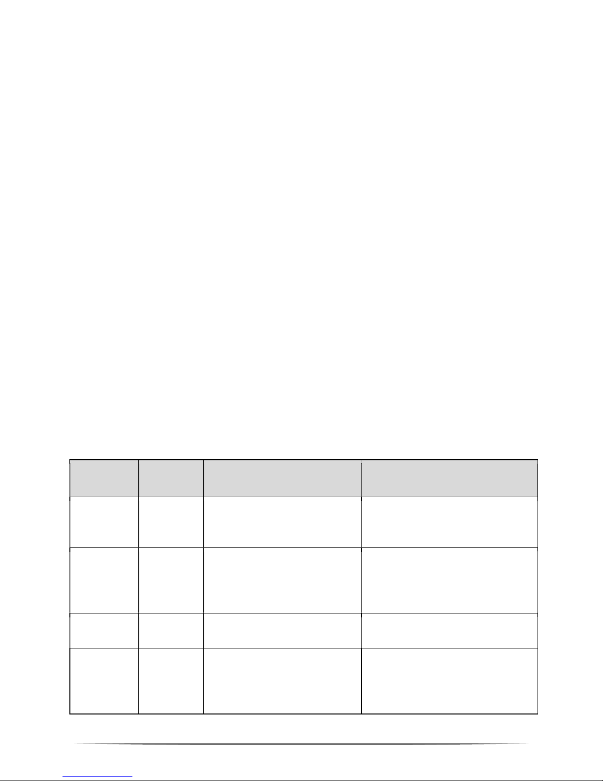
Error
Bit in
error byte
Meaning
Possible action
Bus dead
The CAN bus is not accessable.
Normaly the reason is that the
robot does not have power.
Check all plugs and the emergency
button. See wiki.cpr-robots.com,
section ‘Troubleshooting’
Brown Out
or Watch
Dog
Bit 1
Microcontroller restarted
after a brown out. Supply
voltage was too low or µC got
stuck.
Increase stability of su
pply
voltage. Reset errors.
VelLag
Velocity Lag
Bit 2
Velocity changes too fast
Reset errors
, enable again. Slower
acceleration.
MNE
Motor not
enabled
Bit 3
Not an error. Motor need
s to
be enabled by explicit
command
Enable motor when appropriate.
Page 34
34
COM
Comm
Watch
Dog
Bit 4
Interval without
command
was too long
Provide the position or velocity
commands in a reliable and short
enough time interval. Increase
maxMissedCom.
LAG
Position
Lag
Bit 5
Position is too far away from
the setpoint position
Provide setpoint positions
reachable to the current motor
position. Increase maxLag.
ENC
Encoder
Error
Bit 6
The sequence of the
quadrature encoder pulses did
not fit.
Check connection cable motor
–
motor controller
OC
Over
Current
Bit 7
Current value too high
Decrease applied load on mot
or.
Increase maxCurrent.
CAN
CAN Error
Bit8
CAN error occured
CAN bus to crowded? All
connectrions ok?
A normal state after start-up of the board is an error code of 0x1C (Motor not
enabled, CommWatchDog, PositionLag)
After an error reset the normal state is 0x04 (Motor not enabled).
After enabling the motor the status is 0x00, now the motor is ready to move.
To reach this state, the communication has to provide values in a fast and reliable
way and, when in position control, in the reach of the motor. These restrictions are
taken to prevent unwanted motion due to e.g. a blue screen on the control PC, a
broken communication, or programming bugs.
Page 35
35
11. Troubleshooting
This section offers approaches to solve problems and errors in the areas
Installation, Software and Hardware. If these measures do not solve your problem
please get in contact with us, we are happy to help:
Mail: [email protected]
Please add a description of the problem, the robots serial number (found at
the base) and the three files „install.log“, „startUpLog.txt“ and
„logMessages.log“. They are found in c:\CPRog\.
Phone: ++49 5429 / 37983-4 in Germany, GMT+1
11.1 Installation and Program Start
Error Possible Cause Measures
Error message:
„Windows Version older than
XP. Installation stops.“
Is an
older Windows version
running on the computer?
CPRog needs Windows XP or
higher.
Installation on a computer w
ith
Windows XP or higher.
Program does not start, error
message e.g. „The Application
could not be initialized
correctly (0xc0000135). “
Is the
Microsoft .NET
-
Framework missing?
Install the current .NET f
ramework
from the Microsoft homepage
Program does not start, error
message: "CPRog has
encountered a problem and
needs to close”.
Is and Di
rectX
file missing
?
These files are necessary for
joypad and audio
functionalities.
Install
DirectX Version 9.0
c for
your system. Links can be found
using any search engine.
Program does not start, error
message: „CPRog does not
work any more”
If runn
i
ng on Windows 7: If
CPRog is installed at
c:\Programs or c:\Programs
(x86) it can be started only
with administrator rights.
Right
-
click on the CPRog link on the
desktop, choose „start as
administrator”
11.2 Software CPRog
Error Possible Cause Measures
Connection loss
The robot expects periodically
a message from the CPRog
computer. If this does not have
sufficient free computing
power, the break between two
Reset the errors and
f
ree the motors,
restart the program, see section 5.4.
Avoid these problems by closing
further programs, eventually
disabling the network connection and
Page 36
36
messages may be too long.
the virus scanner.
Does not move any more:
Message “Virtual Box
violated” and warning
sound.
When moving in „Cartesian
Mode” the robot cannot get
out of a virtual box. In “Joint
Mode“ this is possible,
changing back in CartMode
may lead to these warnings.
Change to JointMode and move the
robot back into the virtual Box, e.g.
into a standard position.
The robot does not connect,
the connect button does not
work.
Is the USB
-
CAN a
dapter
plugged in, are the driver
installed?
Is the mains adapter plugged
and switched on?
Is the EmergencyStop button
released?
Do the green status LEDs in
the joint modules blink?
You can find further i
nformation in
the Log-Messages window. The LED
of the USB interface provides
information:
LED slow blinking: power on
LED fast blinking: communication
on the bus, ok
LED on for longer phases:
transmission losses, traffic too
high?
The robot does not react to
the joypad
Has it been activated?
Is the
green ok mark on the joystick
button?
The Log
-
Messages window s
hows if
the joypad has been connected
correctly.
On the joypad: When the red light
beneath the mode button of the
joypad is on, you have to press the
mode button once again.
11.3 Hardware Mover4
Error Possible Cause Measures
Position err
or: the robot
does not proceed to the
same positions as before.
The robot can l
ose its joint
values due to unexpected power
loss or motions of the joints
when the robot is switched off.
Reset the joint zero values
according to section 5.6. Do not
disconnect the robot from energy
while in motion. Do not move the
joints manually.
USB
-
Interface
is not
recognized
Is the USB interface plugged into
a port where it has not been in
before?
With WindowsXP you have to
install the interface driver once for
every port it is plugged in. Use the
assistant that opens automatically.
No motion, no connection
possible
Check all connections and the
emergency stop.
Burnt-out fuse in the robot base?
At the base of
the robot there is a
small fuse cabinet for 5x20 mm
microfuses, 3.1 A. The reason for the
failure should be known and
removed before changing the fuse!
Page 37
37
12. Language Specification
The following nine commands can be combined to form a robot program. A program
is a XML file that starts with the lines
<?xml version="1.0" encoding="utf-8"?>
<!-- values in mm and degree -->
<Program>
<Header ProgramName ="CPRog recording" Author="nn" SetUpDate=""
LastChangeDate="" Kinematic="CPRFour"/>
Then the commands follow, the program closes with the line
</Program>
Command Reference
<Linear Nr="2" x="232.93" y="12.2" z="494.01" a="0.05"
b="84.25" c="0" vel="70" acc="40" smooth="true"
Descr=""/>
<Joint Nr="1" a1="5.19" a2="-26.08" a3="124.72" a4="-14.39"
a5="0" a6="0" velPercent="35" acc="40" smooth="true”
Descr="" />
<Relative Nr="17" x="0" y="0" z="-20.0" a="0" b="0" c="0"
vel="50" acc="40" smooth="true" Descr=""/>
<Gripper Nr="6" Pos="100" Descr="" />
<Output Nr="6" Local="True" DIO="5" State="True" Descr="" />
<Wait Nr="4" Seconds="1" Descr="" />
<Loop Nr="1" Mode="Count" Times="3" Descr=""/>
… place the commands to be repeated here
<EndLoop Nr="1" />
Alternative:
<Loop Nr="1" Mode="DIn" Local="True" Channel="0" State="True"
Descr=""/>
<If Nr="15" Local="True" Channel="0" Descr=""/>
… place the then-commands here
<Else/>
… place the else-commands here
<EndIf/>
<Sub Nr="6" File="up.xml" Descr=""/>
<ExMotion Nr="14" IP="127.0.0.1" Port="1234" Scale="1"
Descr="" />
Page 38

38
Page 39
© Commonplace Robotics
November 2016
 Loading...