

Page 1
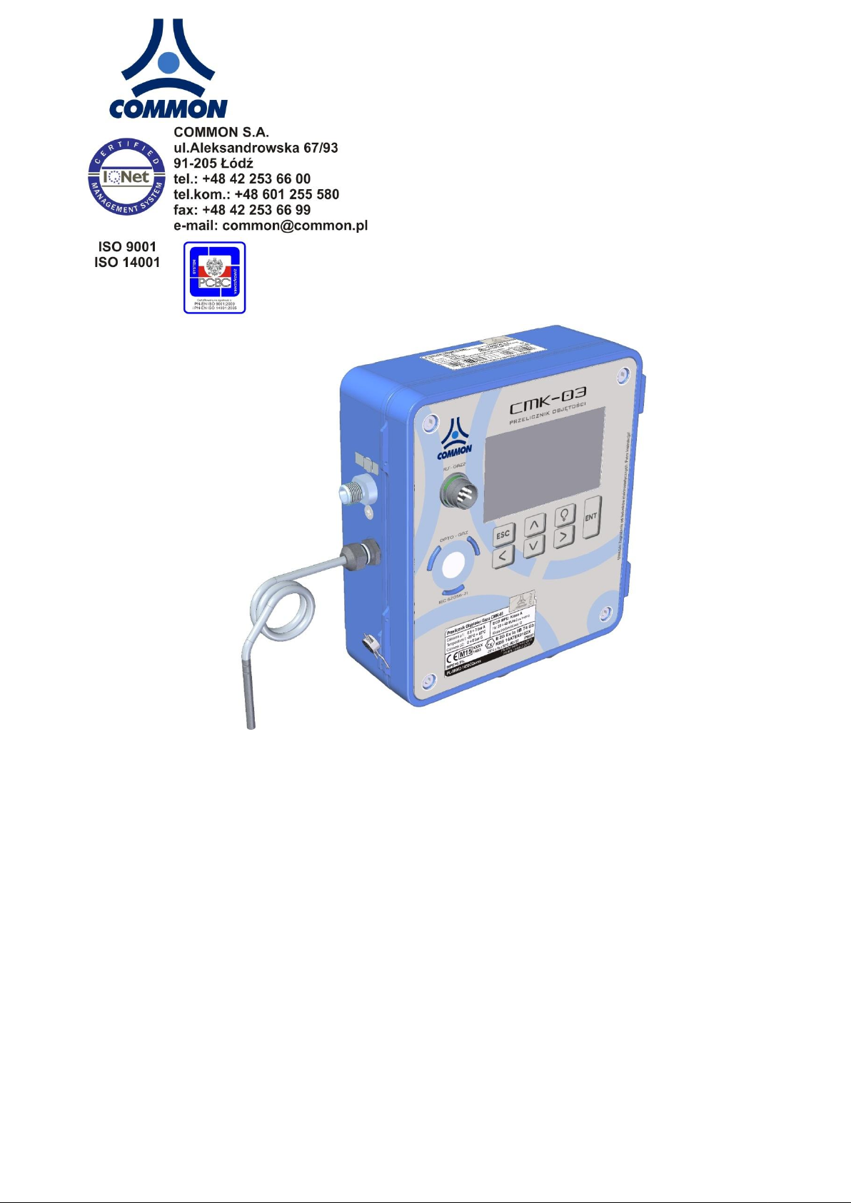
CMK-03 GAS VOLUME CONVERTER
OPERATING INSTRUCTION
Edition: CMK3 / 102U
Firmware version: 2.2.39-39-2.7.8
Lodz, June 2016
Technical specification and construction may change due to improvement. This publication serves as general information only, and all specifications are subject to confirmation by COMMON S.A.
Page 2

COMMON S.A. OPERATING INSTRUCTION CMK-03
CONTENTS
1. INTRODUCTION 5
2. SAFETY AND OPERATION 5
2.1 Transportation 5
2.2 Storage 5
2.3 Periodical inspections 5
2.4 Warranty repairs 6
2.5 List of components and additional accessories 6
3. CONSTRUCTION 9
4. TECHNICAL DATA , CONDITIONS OF USAGE, MEASUREMENT INPUTS 10
4.1 Product code and version of execution 10
4.2 Technical data 12
4.3 Intrinsically safe parameters 17
5. ASSEMBLY AND INSTALLATION 19
5.1 Clamps and outputs 20
5.1.1 TUCHEL port 20
5.1.2 Internal clamps 21
5.2 Cables for intrinsically safe circuits 22
5.2.1 Requirements of cables 22
5.2.2 Parameters and cable types 22
5.3 Protective grounding 26
5.4 Connecting the temperature sensor 27
5.4.1 Connecting the thermometer to the volume converter 27
5.4.2 Connecting the thermometer to the piping 28
5.5 Connection the pressure sensor P1 and P2 29
5.6 Connection the external pressure CPC-03 converter 30
5.6.1 Mechanical installation 30
5.6.2 Electrical connection of CPC-03 30
5.7 Connecting the LF input to the gas meter 31
5.8 Mechanical installation of the CMK-03 — appendix 1 32
5.9 Battery 32
5.9.1 Main battery 32
5.9.2 Battery of LCD backlight 33
5.10 Conditions of safety usage 34
6. GAS VOLUME CORRECTION 34
6.1 Principles of operation 34
6.2 Algorithms 36
6.3 Bio-Gas configuration 37
7. ENERGY CONVERSION 38
8. METROLOGICAL MARKS, PROTECTION SEALS, NAME PLATES 39
8.1 Metrological marks – Seal 1 and Mark IV 39
8.2 Manufacturer protection seals – Seal 2 39
8.3 User protection seals – Seal 3 39
8.4 Marking of name plate 40
8.5 Diagram of sealing 41
Page 3

COMMON S.A. OPERATING INSTRUCTION CMK-03
8.6 Identification of software 43
9. MID ALARMS 43
9.1 Principle of operation and list of alarms 43
9.2 Signalling, authorization and alarm acknowledgement 45
9.3 Principle of operation in the Vbe emergency conditions 45
10. MID INTERFERENCES (CONFIGURATION CHANGES) 46
10.1 Principle of operation and list of parameters 46
10.2 Signalling, authentication and alarms acknowledgment 47
11. LOCAL SERVICE 47
11.1 LCD menu structure 47
11.1.1 Menu Measure 51
11.1.2 Menu Archive 53
11.1.3 Menu Clock 57
11.1.4 Menu Name plate 57
11.2 Menu Settings 57
11.2.1 Configuration after installation 57
11.2.2 Parameters settings – general information 58
11.2.3 Log in 59
11.2.4 Settings of COM Ports parameters 60
11.2.5 Registration 62
11.2.6 Gas meter 62
11.2.7 Measure 62
11.2.8 Limits and “gas guard” function 64
11.2.9 Gas 66
11.2.10 Simulation 67
11.2.11 Inputs IN 68
11.2.12 Outputs OUT 69
11.2.13 Control of odorizing unit, OUT1 output proportional to Vbs 70
11.2.14 LCD 71
11.2.15 Users 71
11.2.16 Clock 72
12. SETTINGS OF EXTENDED FUNCTIONALIETIES 73
12.1 Summary alarms 73
12.2 Control of the gas meter FF/LF constant error 73
12.3 Operating below Qmin of the gas meter – in range QmSTOP <–> QmMIN 74
12.4 LCD power supply 74
12.5 Reserve1 configuration in GAZ-MODEM 74
12.6 Activity time of OPTO-GAZ port 75
13. REMOTE CONTROL OF CMK-03, USERS, AUTHORIZATION 75
13.1 CCTool configurator 75
13.1.1 Connection by using COGUSB-03 76
13.1.2 Users and authorization 77
14. DATA REGISTRATION, READING AND CONFIRGURATION IN TELEMETRIC SYSTEMS 78
14.1 Registered data 78
14.1.1 Data registered with registration period and and daily registered data 79
3
Page 4

COMMON S.A. OPERATING INSTRUCTION CMK-03
14.1.2 Events 81
14.2 Reading and configuration in the telemetric systems 82
15. ENVIRONMENTAL PROTECTION 83
15.1 Packaging waste 83
15.2 Disposal of used batteries and devices after life-time 83
16. HISTORY OF THE DOCUMENTATION CHANGES 84
17. NOTES 84
4
Page 5
COMMON S.A. OPERATING INSTRUCTION CMK-03
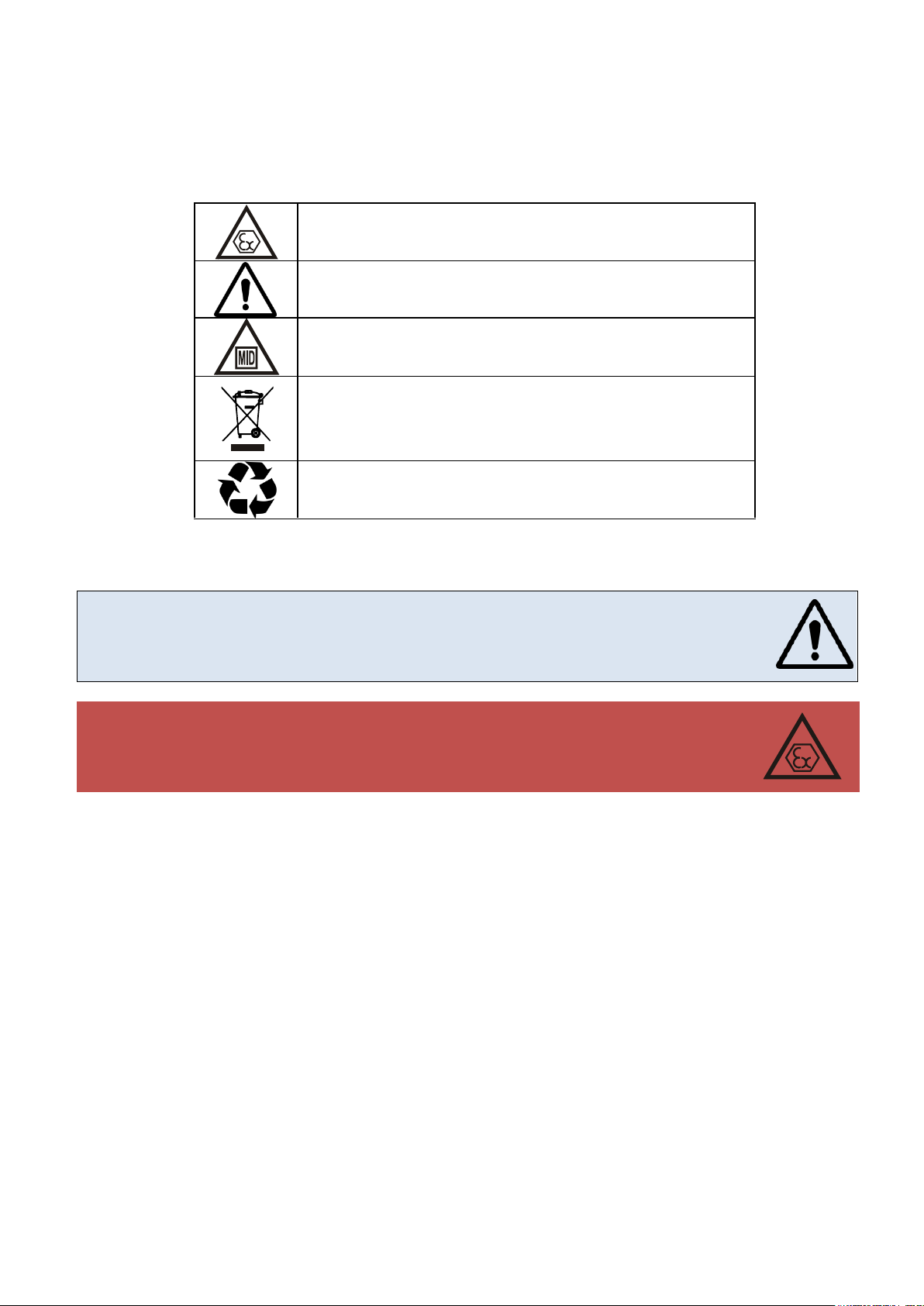
ATEX Directive requirements (intrinsic safety)
installation and usage
MID Directive requirements
Packaging Regulations requirements (used accumulators and
devices after their life time).
recyclable packages
The CMK-03 can be installed and operate in explosion hazard zone 1 or 2. The device can
cooperate with the intrinsically safe circuits on security level “ia” or “ib”. The subgroup
conformity of the potentially gas mixture has to be maintained with the subgroup of device
circuits (IIA or IIB) and temperature T4 class.
The CMK-03 can be connect to the intrinsically safe circuits of other devices, only accordingly to the safety rules of usage which are contained in the certificates and manufacturer instructions of this devices. The conformity of the intrinsically safe parameters
has to be maintained for connected devices.
1. INTRODUCTION
The CMK-03 Gas Volume Converter is a Type 1 converter (according to EN12405-1 + A2:2010) which fully meets
the requirements of the MID Directive.
2. SAFETY AND OPERATION
The following warning marks are used in this manual:
The installation and connection of the CMK-03 requires to follow according to recommendations of this operating
instruction. The device should be used according with the regulation and rules of the explosion hazard safety.
2.1 Transportation
The transportation should be carried out in the original packaging, which secures the device against the mechanical damage and assure a proper level of protection.
2.2 Storage
The elements of the CMK-03 should be storage in the original package in room with temperature from -20°C till
+60°C and humidity which does not exceeding 80%, without vapour and chemically active compounds.
2.3 Periodic inspections
The CMK-03 is dedicated to installation and operation in the explosion hazard zones. To be sure that device and
the installation system allows for safety usage, it is necessary to implement a regular periodical inspections or
assure a continuous supervision by the qualified personnel. The proper services should be carried out in every
necessary case.
The detailed guidelines regarding to the control frequency and control level can be found in the standard EN
60079-14:2008.
The devices with "X" sign in the certificate number have a special condition of usage, which are precisely described in the certificate documentation.
5
Page 6
COMMON S.A. OPERATING INSTRUCTION CMK-03
The manufacturer or a recommended authorized workshops should perform warranty repairs of the CMK-03. The method of usage after warranty repairs and post-warranty repairs,
should be consistent with the regulations of the country where the device is installed.
WARNING !
The removing or damage of manufacturer protection seal means the loss of guarantee
and loss of intrinsically safe characteristic.
List of components:
CMK-03 Gas Volume Converter operating instruction
guarantee card
initial verification certificate (if there is present a mark of the initial verification)
gasket of pressure connection M12 thread (type O-ring, dimensions 9,3x2,4mm)
transporting cover of the pressure converter (plug P1, P2)
cable glands plugs in dimension 6mm and 8mm
sealed, protective covers for the PT1000, LF and HF clamps
NR
additional accessories, set name: example drawing
1
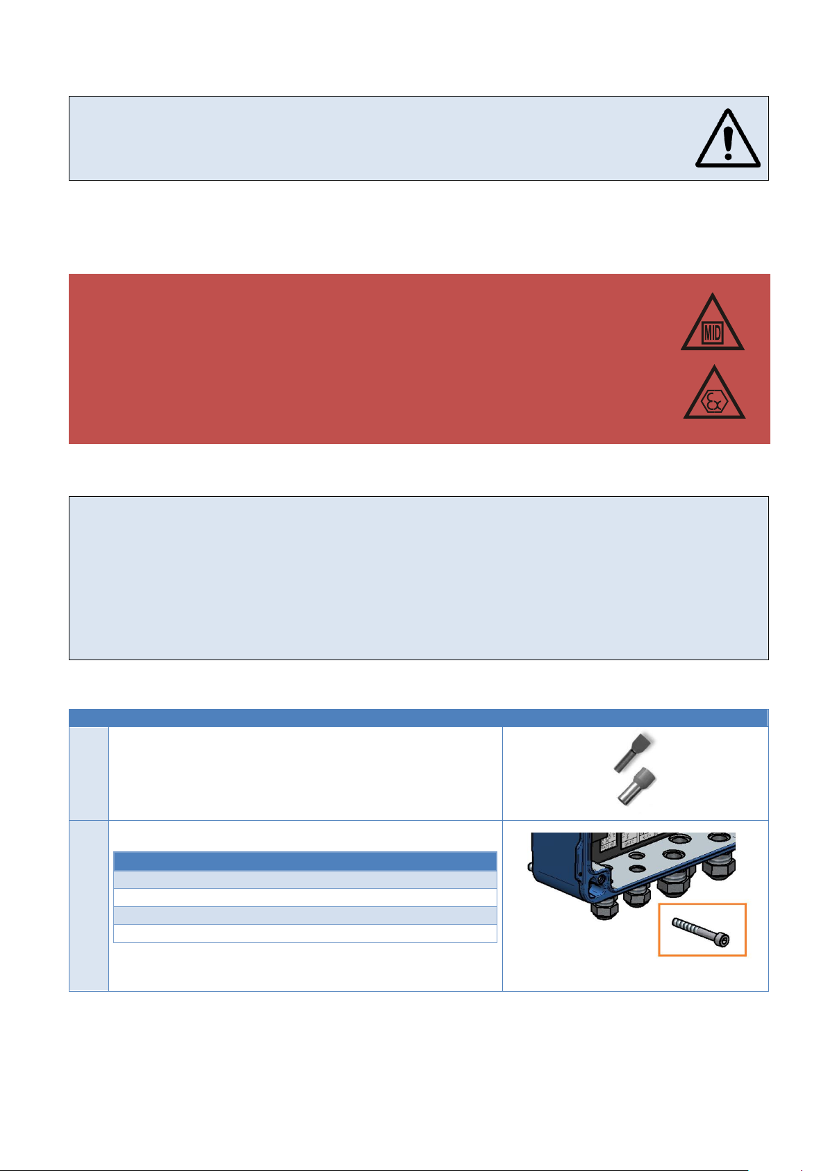
cable sleeves for finishing the wires assembled on clamps:
size 0,25mm2/ 8-10mm - 100 pcs.
size 0,34mm2/ 8-10mm - 100 pcs.
size 0,5mm2/ 8-10mm - 100 pcs.
size 0,75mm2/ 8-10mm - 100 pcs.
2
Assembly set through the holes in the housing
Part name
Quantity
bolt (cylinder type) M5x45
4
washer M5
4
nut M5
4
see part 5.8.1
2.4 Warranty repairs
The CMK-03 should be disassembled from the operating point in case of doubt regarding the correctness of
instrument indications. The device should be pass to the appropriate laboratory for checking and verification. The
checking may be carried out by means of control instruments without damage or removing the manufacturer's
protection seals.
2.5 List of components and additional accessories
Table 2.1 Additional Accessories
6
Page 7
COMMON S.A. OPERATING INSTRUCTION CMK-03
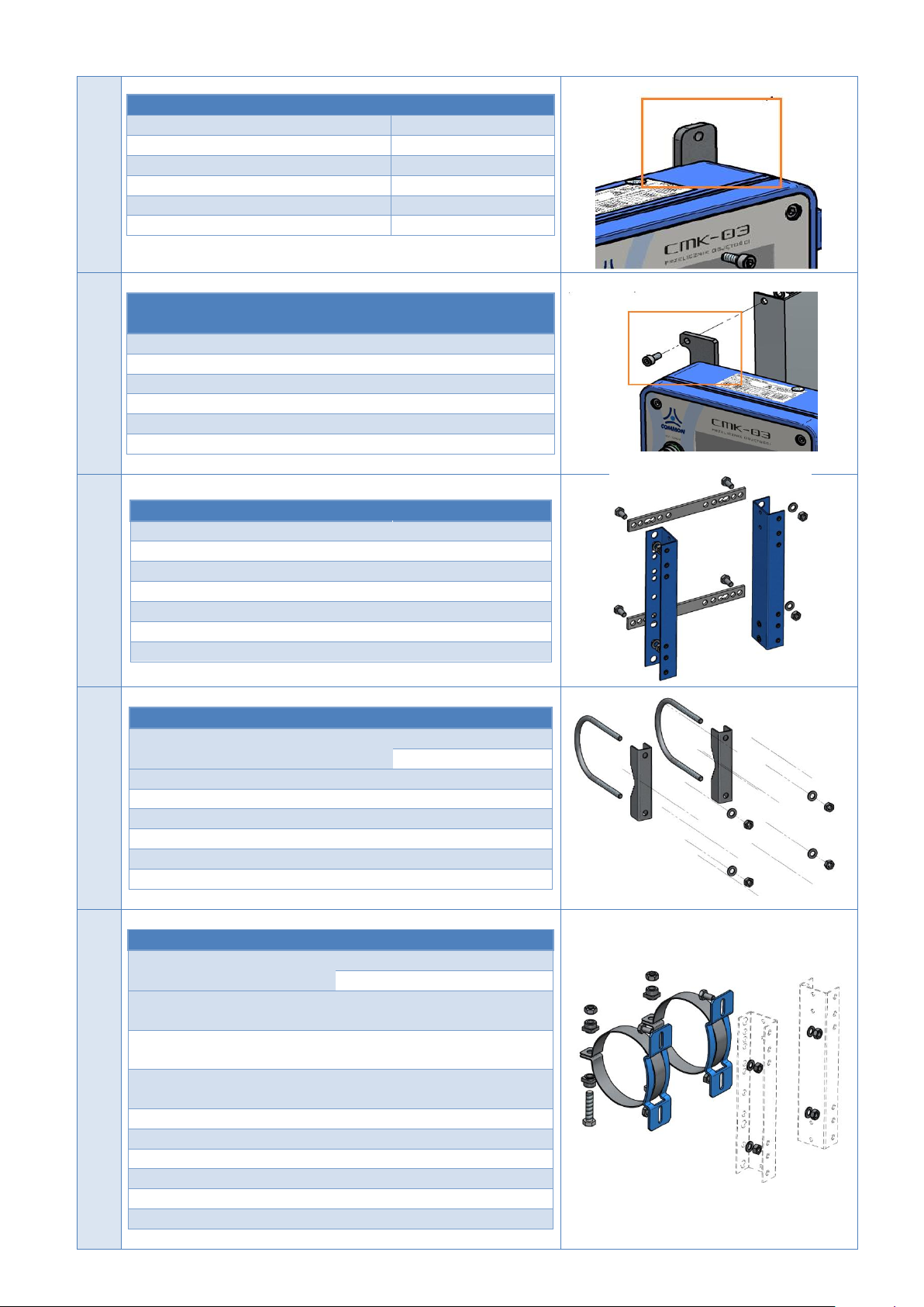
3
Assembly set: O-Type, flat handles
Part name
Quantity
O-Type, flat handle
4
bolt (cylinder type) M5x40
4
bolt (cylinder type) M5x12
4
washer M5
4
nut M5
4
see part 5.8.2
4
Assembly set: L-Type, flat handles, the replacement
of the CMK-02
Part name
Quantity
L-Type, flat handle
4
bolt (cylinder type) M5x40
4
bolt (cylinder type) M5x12
4
washer M5
4
nut M5
4
see part 5.8.3
5
Assembly set with the universal hangers
Part name
Quantity
left hanger universal set
1
right hanger universal set
1
universal strip of pipe holder
2
bolt M8x16
4
washer M8
4
nut M8
4
see part 5.8.4
6
Assembly set with the pipe holders
Part name
Quantity
DN50
DN80
pipe holder M8 x 61 (2")
2
-
pipe holder M8 x 89 (3")
-
2
connector of pipe holder ŁC8.61
2
-
connector of pipe holder ŁC10.89
-
2
washer M8
4
4
nut M8
4
4
see part 5.8.5
7
Assembly set with the pipe clamp
Part name
Quantity
DN100
DN150
DN200
clamping ring with bolt
DN100
2 - -
clamping ring with bolt
DN150
- 2 -
clamping ring with bolt
DN200
- - 2
base of band clip DN100
2 - -
base of band clip DN150-200
- 2 -
base of band clip DN150-200
- - 2
bolt M8x16
4 4 4
washer M8
4 4 4
nut M8
4 4 4
see part 5.8.5
7
Page 8
COMMON S.A. OPERATING INSTRUCTION CMK-03
8
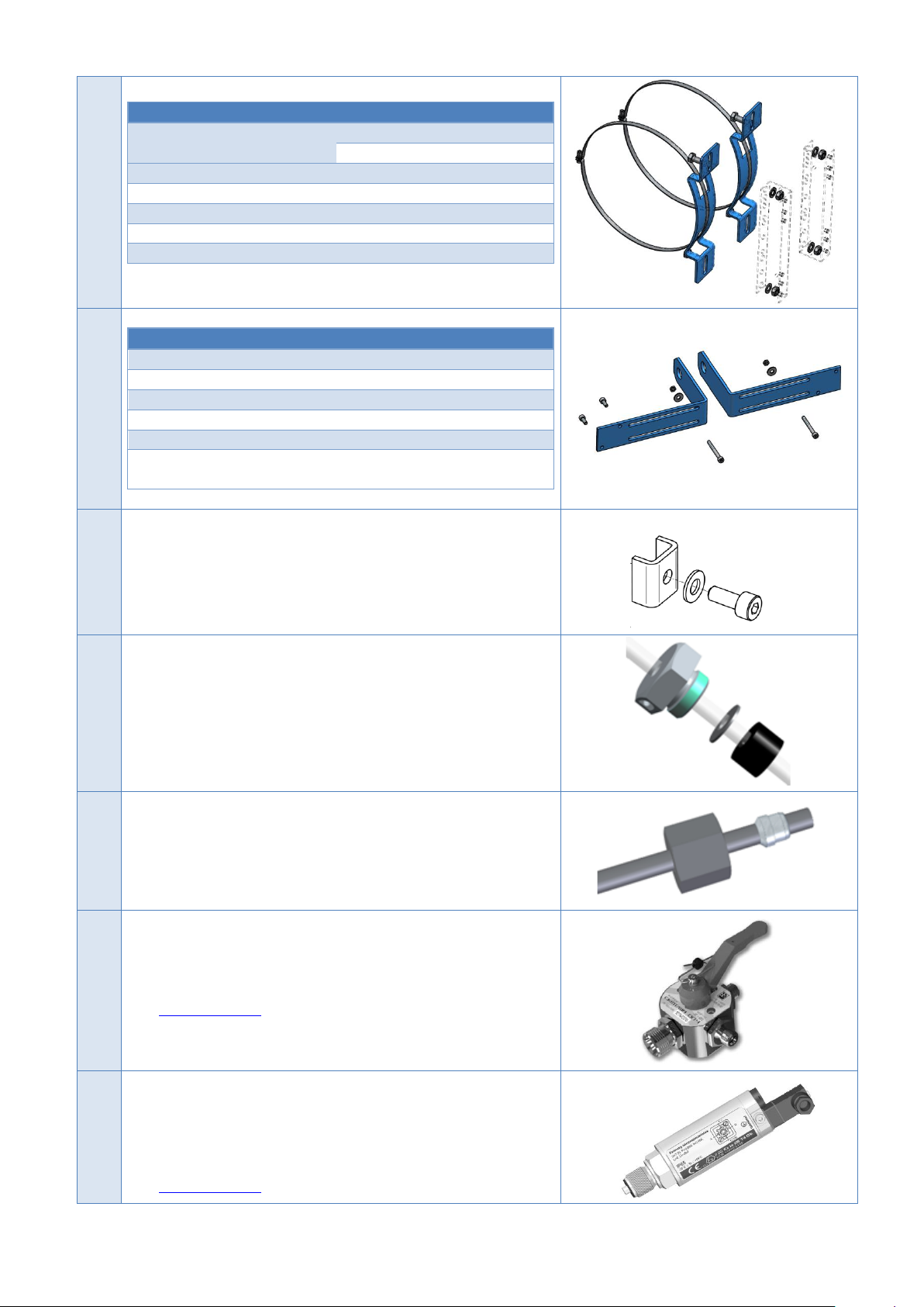
Assembly set with the band clips
Part name
Quantity
DN250
DN300
band clip with lock
2
2
base of band clip DN250-300
2
2
bolt M8x16
4
4
washer M8
4
4
nut M8
4
4
see part 5.8.5
9
Assembly set with bars mounted into collar
Part name
Quantity
assembly bars into collar
2
bolt (cylinder) M5x45
2
washer M5
2
nut M5
2
bolt (cylinder type) M5x12 (assembly of the
CKMT valve)
2
see part 5.8.6
10
grounding clamp elements: plate + spring washer + bolt (available in
the CMK-03 set; spare part)
11
The assembly set of thermometer in the thermowell; the set is
adapted to sealing by the cord – bolt nut, washer, seal
see part 5.4.2
12
The tightening nut M12x1,5 of the pressure measurement pipe,
sleeve, pulse pipe.
The length and material (cooper or acid-resistant stainless steel)
have to be indicate by the order.
13
The CKMT three way manometrical valve.
The detailed information are contained in the service manual and
the technical documentation of this device — available on the web
site: www.common.pl
14
The CPC-03 Pressure Converter
The selected information about converter are described in the Table
4.5 — “The measuring converters of the CMK-03".
The detailed information are contained in the service manual and
the technical documentation of this device — available on the web
site: www.common.pl
8
Page 9
COMMON S.A. OPERATING INSTRUCTION CMK-03
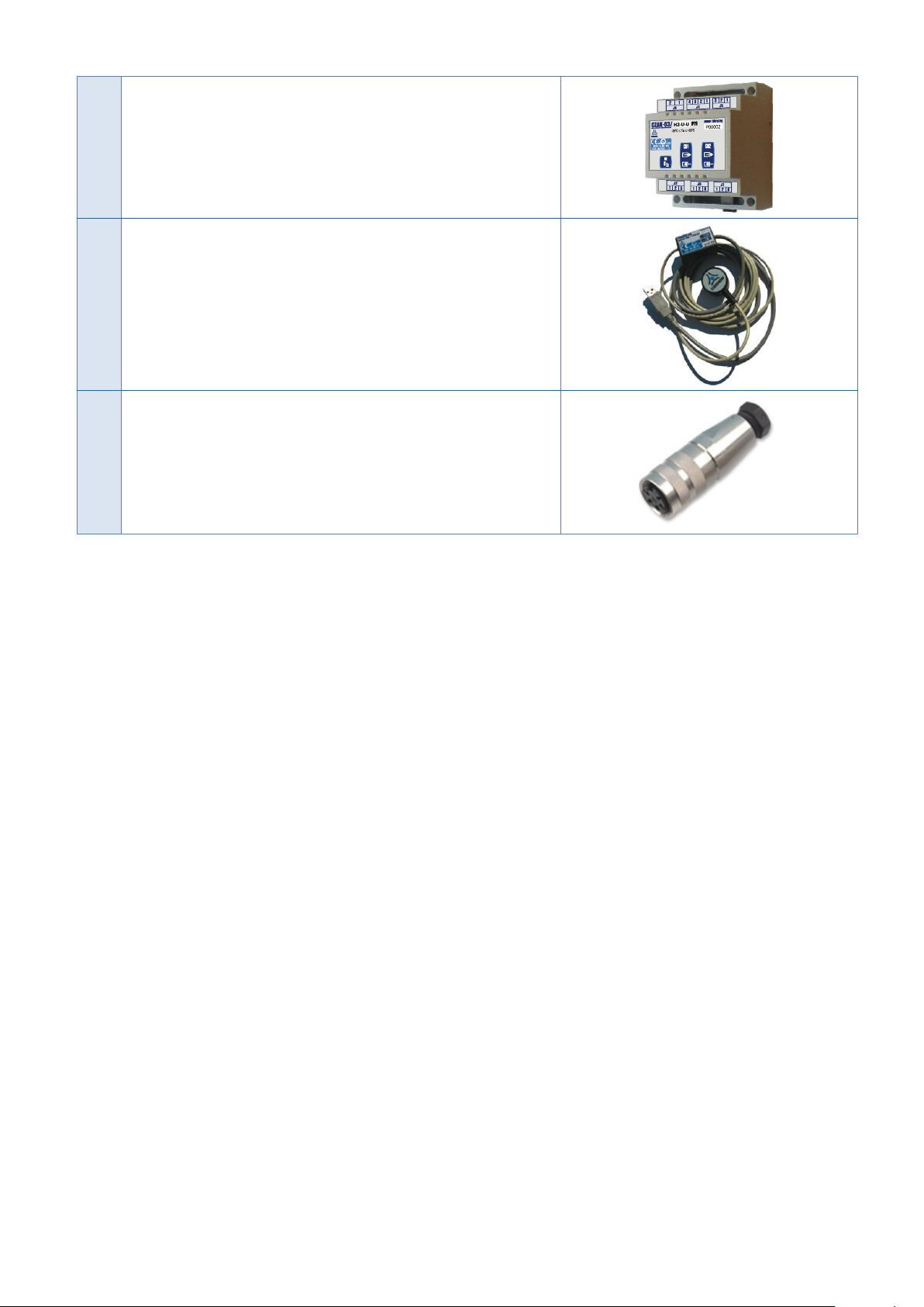
15
The CZAK-03 Communication and Signal Barrier
The detailed information are contained in the manual instruction and
the technical documentation of this device — available on the web
site www.common.pl
16
Optical communications interface COGUSB-03.
Detailed information contains manual instruction and technical documentation of the device available on web site: www.common.pl
17
The female, TUCHEL contact, C091D Type (to the COM1 transmission port)
3. CONSTRUCTION
The CMK-03 Gas Volume Converter is a measuring and accounting instrument which fulfills the requirements of
MID Directive. The device is dedicated to operate on the measuring and reducing & measuring gas stations. It
can be used with any of the gas meter (turbine, rotor or ultrasonic) which provides information about measured
volume in the pulses.
The CMK-03 is a battery power supplied instrument with possibility to operate on the external power supply. The
installed batteries provide continuous and service less data registration for a minimum 6 years.
The CMK-03 is a volume converter of the gas Type 1. This is complete measurement system, equipped in the
pressure converters, the temperature converters, the input of pulses/volume of the meter and the algorithms for
converting the measured volume of gas to the basic conditions.
The construction of the CMK-03 has an additional inputs and outputs, which allow for a usage to the technological
purpose and to the control and measurement processes. The inputs and outputs are listed below:
control inputs LFb and LFc
Encoder input,
HF transmitter input in NAMUR standard
double ExtCPC input for external technological CPC-03 converters,
double-state, signal outputs OUT
double-state, signal inputs IN
input IN in NAMUR standard
The data reading and also the CMK-03 power supply are carried out by using three independent communication
ports in the RS-GAZ2 standard: COM1 ("Tuchel/OPTO-gas"), and COM2 and COM3.
The housing is made from the aluminum what assure durability, resistance and a high level of waterproofness —
IP66/67. The opening of the cover is a hinge with the limiter what allows for easy access to the wire clamps and
the battery unit.
The LCD display with keyboard, the port OPTO-GAZ port and the RS-GAZ2 (TUCHEL) port are located in the
device cover. There are maximum two pressure converters P1 and P2 which are built in the housing base.
The P1 Converter occurs also as an external version which is constant connected via a cable with the CMK-03.
The metal cable glands are located in the base of the housing. They are adapted for the shielded cables. This
solution raises the resistance of the device electrical circuits against the electromagnetic interference.
9
Page 10
COMMON S.A. OPERATING INSTRUCTION CMK-03
The protection level of housing will be preserved if the conditions will be filled as listed
below:
appropriate diameters of the connection cables
correct tightening of the cable gland,
proper positioning of the gaskets and tightening of the housing cover
The CMK-03 is equipped in the LCD display with graphical-text menu. The LCD is readable in the entire temperature range. The display backlight is supported by the additional battery which is independent of the converter
main battery.
4. TECHNICAL DATA, USAGE CONDITIONS, MEASUREMENT INPUTS
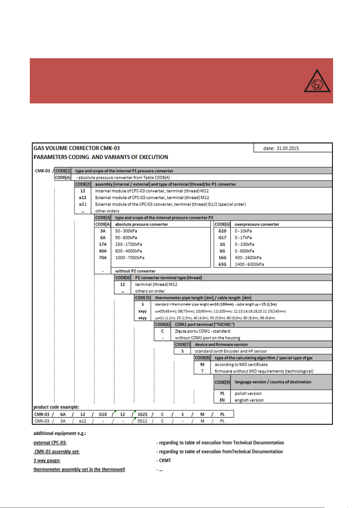
4.1 Product code and version of the execution
Table 4.1 Code of product and versions
10
Page 11
COMMON S.A. OPERATING INSTRUCTION CMK-03
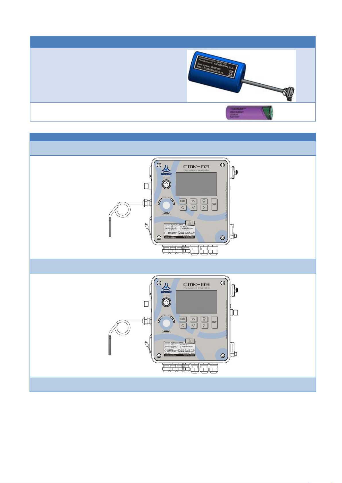
NR.
PART DESCRIPTION:
TYPE:
EXAMPLE DRAWING
1
Main battery
BAT-03 manufactured by
COMMON S.A.
2
LCD backlight battery
SL-760 Xtra manufactured by
Tadiran
EXAMPLES OF THE CMK-03 VARIANTS
CMK-03/x/12/-/-/0512/….
CMK-03/x/12/x/12/0512/….
CMK-03/x/e12/x/12/0512/….
Table 4.2 The spare parts list
Table 4.3 The examples of the CMK-03 available variants
11
Page 12
COMMON S.A. OPERATING INSTRUCTION CMK-03
MARKINGS
meteorological markings and MID certificate number
1450 PL-MI002-1450CQ0001
Explosion proof construction
II 2G Ex ia IIB T4 Gb
markings and ATEX certificate number
1453 KDB 14ATEX0102X
conformity with norms and directives
94/9/WE ATEX:
PN-EN 60079-0:2013-03 + A11:2014-03 (EN 60079-0:2012/A11:2013 [IDT])
PN-EN 60079-11:2012 (EN 60079-11:2012 [IDT])
2004/22/WE (MID):
PN-EN 12405-1+A2:2010 (EN 12405-1:2005+A2:2010 [IDT])
energy calculation:
PN-EN 12405-2:2012 (EN 12405-2:2012 [IDT])
2004/108/WE (EMC):
PN-EN 12405-1+A2:2010 (EN 12405-1:2005+A2:2010 [IDT])
PN-EN 55016-2-3: 2010 + A1: 2010 (EN 55016-2-3: 2010 + A1: 2010)
PN-EN 55011:2012 (EN 55011:2009, EN 55011:2009/A1:2010)
OPERATING CONDITION
ambient temperature
(-25°C +55 °C)
relative humidity
max 95% In temp. 55°C, possibility of condensation of water vapor
electromagnetic environmental conditions
class E2 (class of protection)
mechanical environmental conditions
class M2
environmental conditions
class O – for inside and outside room installation
HOUSING
metal
aluminum cast – pressure method
the protection level of the housing
IP66/67
dimensions (total, without terminals)
height - 190 mm, width - 170mm, depth - 70 mm
front, elevation, keyboard, display
polycarbonate or polyester 185 x 165 mm
7 keys
Graphic, backlight display 240x128
closing
cover with housings gasket on hinge. Closed with 4 cylinder bolts 4mm
grounding
clamp for ground connection stainless steel, max. cable cross-section
16mm2, cylinder bolt key size 3mm
weight
2,4kg
4.2 Technical parameters
Table 4.4 The technical parameters
12
Page 13
COMMON S.A. OPERATING INSTRUCTION CMK-03
THE HOUSING OF THE CPC-03e EXTERNAL CONVERTER
(variant with external p1, look at the Table 4.3)
metal
acid-resistant stainless steel
protection level of housing
IP66/67
dimension (total)
total length 90 mm, diameter 38mm
connection with CMK-03 volume converter
factory mounted permanent connection. Cable length – 2,5m.
POWER SUPPLY
main internal
2 sets of battery type: BAT-03 manufactured by COMMON S.A. (execution
KOD(7)=S).
life time of battery set – minimum 5 years in typical operating conditions
(detailed information – part 5.9.2)
internal for LCD backlight
SL-760 Xtra Or TL-5903 manufactured by Tadiran
external
CZAK-03 power supply unit with NAMUR which output assures EX circuit
separation / manufactured by COMMON S.A.
other power supply unit with input parameters (Un = 57,14V ; In=65mA) by
maintaining intrinsically safe parameters.
Intrinsically safe parameters – Table 4.13
resistance of the electric insulation
500V AC
WARNING!
The input circuit on the COM2 and COM3 ports contain the protective, overvoltage safety elements which secure the electrical terminals on the level approx. 90 V towards
housing.
P1 PRESSURE CONVERTER
(parameter under metrological control)
converter type
built-in sensor or sensor on the cable ended with thread (code 2 / Table 4.1)
terminal type
M12 x1,5 (others variants on the special order)
GAS PRESSURE MEASUREMENT RANGES FOR P1 CONVERTER
(code 1 / Table 4.1)
absolute pressure converters
3A 0,5 3 bar abs
6A 0,9 6 bar abs
17A 2,5 17 bar abs
40A 6 40 bar abs
70A 10 70 bar abs
P2 PRESSURE CONVERTER
converter type
built-in sensor ended with the M12 X 1.5 thread (code 4 / Table 4.1)
terminal type
M12 X 1.5 (others variants on the special order)
GAS PRESSURE MEASUREMENT RANGES FOR P2 CONVERTER
(code 3 / Table 4.1)
absolute pressure converters
gauge pressure converters
3A 0,5 3 bar abs
6A 0,9 6 bar abs
17A 2,5 17 bar abs
40A 6 40 bar abs
70A 10 70 bar abs
G10 0 10 kPa G
G17 0 17 kPa G
1G 0 100 kPa G
6G 0 600 kPa G
16G 400 1600 kPa G
63G 1400 6300 kPa G
t — TEMPERATURE CONVERTER
(parameter under metrological control)
converter type
built-in converter with attached PT1000 resistance thermometer class 2/3A ( ± 0,1o C)
CTA4 Type manufactured by COMMON S.A.
The thermometer is permanent connected with the volume converter via a cable. The
thermometer is marked with a serial number. The serial number is readable on the LCD
(code 5 / Table 4.1)
The connection clamps of the thermometer are secured with the sealed cover by the
user or manufacturer.
measuring range of gas temperature
-25°C +65°C
thermometer cable length
to 10 m (code 5 / Table 4.1)
Table 4.5 The measuring converters
13
Page 14
COMMON S.A. OPERATING INSTRUCTION CMK-03
outer diameter of the
thermowell
6mm
CPC-03 DIGITAL CONVERTERS (EXTERNAL, SWITCHABLE)
FOR THE P3, P4 PRESSURE MEASUREMENT
converter type
The external CPC-03 digital pressure converters manufactured by COMMON S.A. (ordered separately)
terminal type
M20 X 1.5 thread (others variants on the special order according to the CPC-03 instruc-
tion
level of housing protection
IP 66/67
operating temperature
-25 oC to +55 oC
relative humidity
max 95% in temp 55°C
supply
external from the ExtCPC clamps
GAS PRESSURE MEASUREMENT RANGES OF THE P3, P4 CONVERTERS
absolute pressure converter
gauge pressure converters
3A 0,5 3 bar abs
6A 0,9 6 bar abs
17A 2,5 17 bar abs
40A 6 40 bar abs
70A 10 70 bar abs
G10 0 10 kPa G
G17 0 17 kPa G
1G 0 100 kPa G
6G 0 600 kPa G
16G 400 1600 kPa G
63G 1400 6300 kPa G
LF PULSE INPUTS
(parameter under metrological control)
DESCRIPTION
LF pulse input from the index head of gas meter
parameters
maximum frequency 2 Hz,
minimum pulse durations – 200ms,
compatibility with:
reed relay transmitter,
electronic, potential–free contact (open-collector, open-drain),
Wiegand type transmitter
resistance of the closed state < 50k,
resistance of the open state > 500 k
pulse value
0,01 ; 0,1 ; 1; 10 m3/imp
LFb, LFc, HF PULSE INPUTS
LFb
double-state input. The control circuit (LFbreak)
LFc
double-state input. The programmable function: counting, directional
HF
high frequency pulses input of the HF sensor. The NAMUR interface. Fmax=5kHz.
WARNING! the external power supply +8,2V is required to the COM3 port.
INx SIGNAL INPUTS
IN1,
IN2,
IN3,
IN4,
IN5,
IN6.
double-state inputs
compatibility with
reed relay transmitter,
electronic, potential–free contact (open-collector),
Wiegand type transmitter.
IN5 and IN6 are software set as a switchable to the operation as a double-state input or NAMUR
standard.
WARNING! The operating mode in the NAMUR standard requires the external power supply
+8,2V to the COM3 port
OUTx SIGNAL OUTPUTS
OUT1,
OUT2,
OUT3,
OUT4.
signaling double-state outputs – open collector. (Ui=10V, Ii=0,3A)
programmable, released by the control function or by the alarm.
Possible operating modes:
OUT2 – steering output of the odorizing unit
OUT2 – frequency output proportional to the selected parameter
OUT3 – representation of the LF input signal
OUT3 – representation of the HF input signal
ENC INPUTS
The input compatible with the CWSL–N Type Encoder digital encoder manufactured by COMMON S.A.
Table 4.6 Inputs and Outputs
14
Page 15
COMMON S.A. OPERATING INSTRUCTION CMK-03
ExtCPC INPUTS
There is a dual input dedicated to the connection for maximum two of the external CPC-03 digital pressure converters.
The input assures the power supply for P3 and P4 converters and digital data transmission to the CMK-03 (also in the battery supply working mode).
COUNTERS
(under metrological control)
Vm [m3] - volume counter in measuring conditions
capacity and total precision
11.2 significant place
display format on the LCD
11.2 significant place
Vb [m3] - volume counter in base conditions
capacity and total precision
11.8 significant place
display format on LCD
11.3 significant place
Vbe [m3] - volume counter in emergency conditions
capacity and total precision
11.8 significant place
display format on LCD
11.3 significant place
OTHER COUNTERS
E [kWh] – energy counter
Ee [kWh] – energy counter in emergency conditions
capacity and total precision
11.8 significant place
LCD displaying format
11.3 significant place
Vbs [m3]= Vb + Vbe
summary counter of the base volume
capacity and total precision
11.8 significant place
LCD displaying format
11.3 significant place
Es [m3]= E + Ee
summary energy count
capacity and total precision
11.8 significant place
LCD displaying format
11.3 significant place
MID ALARMS REGISTER
(metrological significant)
Size of the MID alarms base
minimum 256 records (max. 288)
Protection against data removing
acknowledgment with user authorization
Rotary register
the oldest data are deleting and overwriting with the
latest, only when the alarms are acknowledged and
completed
MID INTERFERENCES REGISTER
(metrological significant)
Size of the MID interferences register base
minimum 128 records (max.144)
Rotary register
the oldest data are deleting and overwriting with the
latest
DATA TRANSMISION
communication ports:
COM1
COM2
COM3
RS-GAZ2 interface – four wire communication port with the supply line V+, GND and RS-485
standard transmission lines in the intrinsically safe execution up to 115200 bits/s.
WARNING! COM1 port is a “male” TUCHEL socket on housing.
Port OPTO-GAZ
The optical transmission interface accordant with the EN 62056-21 standard. Baud rate up to
115200 bits/s by using COGUSB-04 interface manufactured by COMMON S.A.
WARNING! COM1 and OPTO-GAZ ports are shared. The active OPTO-GAZ port blocks
transmission on the COM1 port.
WARNING !
The input circuit on the COM2 and COM3 ports contain the protective, overvoltage safety elements which secure the electrical terminals on level approx. 90 V towards the housing.
Table 4.7 Measuring counters
Table 4.8 The register of the alarms and MID interferences
Table 4.9 Data transmission
15
Page 16
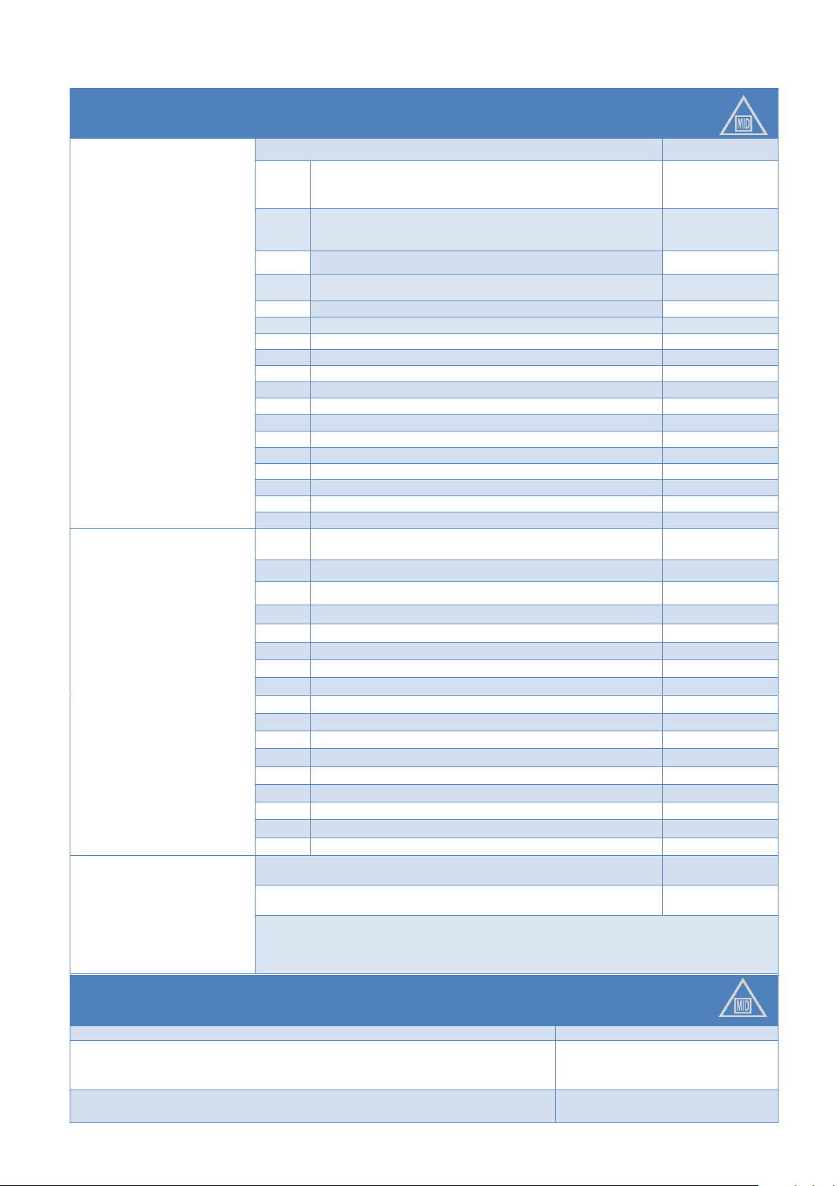
COMMON S.A. OPERATING INSTRUCTION CMK-03
CALCULATING METHODS FOR COMPRESSIBILITY COEFFICIENT
SGERG-88
calculating in function of
PTZ
according to PN-EN ISO
12213-3:2011
(EN ISO 12213-3:2009 [IDT])
APPLICATION RANGE (extended)
UNIT
p1
t
0,5 3; 0,9 6; 2,5 17
-23,15 +65
bar abs
°C
p1
t
6 40; 10 70
-10 +65
bar abs
°C
Hs
20 48
% mole
d
0,55 0,9
% mole
CO2
0 30 (carbon dioxide)
% mole
H2
0 10 (hydrogen)
% mole
N2
0 50 (nitrogen)
% mole
CH4
50 100 (methane)
% mole
C2H6
0 20 (ethane)
% mole
C3H8
0 5 (propane)
% mole
C4H10
0 1,5 (butane)
% mole
C5H12
0 0,5 (pentane)
% mole
C6H14
0 0,1 (hexane)
% mole
C7H16
0 0,05 (heptane)
% mole
C8+
0 0,05 (octane and higher hydrocarbons)
% mole
CO
0 3 (carbon monoxide)
% mole
He
0 0,5 (helium)
% mole
H2O
0 0,015 (water)
% mole
AGA8-92DC
calculating in function of
PTZ
according to PN EN ISO
12213-2:2010
(EN ISO 12213-2:2009 [IDT])
p1
t
0,5 3; 0,9 6; 2,5 17; 6 40; 10 70
-23,15 +65
bar abs
°C
Hs
20 48
MJ*m-3
d
0,55 0,9
-
CO2
0 30 (carbon dioxide)
% mole
H2
0 10 (hydrogen)
% mole
N2
0 50 (nitrogen)
% mole
CH4
50 100 (methane)
% mole
C2H6
0 20 (ethane)
% mole
C3H8
0 5 (propane)
% mole
C4H10
0 1,5 (butane)
% mole
C5H12
0 0,5 (pentane)
% mole
C6H14
0 0,1 (hexane)
% mole
C7H16
0 0,05 (heptane)
% mole
C8+
0 0,05 (octane and higher hydrocarbons)
% mole
CO
0 3 (carbon dioxide)
% mole
He
0 0,5 (helium)
% mole
H2O
0 0,015 (water)
% mole
K1=const
calculating in function of PT
K = 1
p1 < 1,5
-
bar abs
K ≠ 1
p1 < 1,5
bar abs
WARNING!
For K1=const.≠1 it is necessary to configure ranges of pressure and temperature (dlp1K1,
glp1K1, dltK1, gltK1) that in this ranges change of p1 and t not cause error greater than
0,25% of K1
REFERENCE CONDITIONS
Basic pressure to the volume calculation
pb = 1.01325 bar
Basic temperature to the volume calculation
Tb = 273.15 K (0°C)
Tb = 288.15 K (15°C)
Tb = 293.15 K (20°C)
Reference temperature of the combustion processes (out of the legal metrological control)
T1 = 273.15 K (0°C)
T1 = 288.15 K (15°C)
Table 4.10 Compressibility coefficient – the calculating methods
16
Page 17
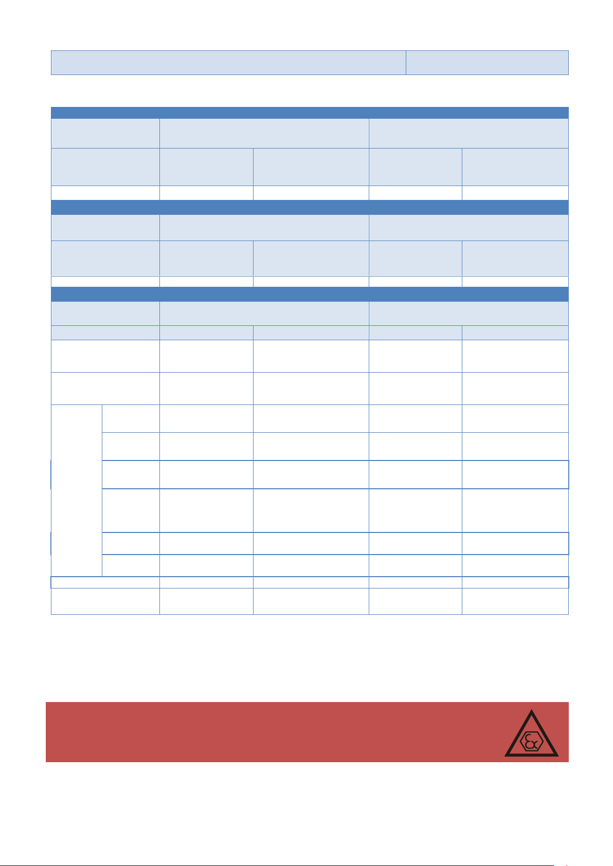
COMMON S.A. OPERATING INSTRUCTION CMK-03
T1 = 293.15 K (20°C)
T1 = 298.15 K (25°C)
VALUE UNDER METROLOGICAL CONTROL
REFERENCE CONDITIONS
T
amb
= (+20 ± 3) °C
OPERATING CONDITIONS
T
amb
= (-25 +55) °C
INDICATION
TYPICAL ERROR
LIMITING ERROR MPE
(acc. PN-EN 12405-
1+A2:2010)
TYPICAL ERROR
LIMITING ERROR MPE
(wg. PN-EN 12405-
1+A2:2010)
Vb
< 0,2 %
0,5 %
< 0,4 %
1 %
ENERGY
REFERENCE CONDITIONS
T
amb
= (+20 ± 3) °C
OPERATING CONDITIONS
T
amb
= (-25 +55) °C
INDICATION
TYPICAL ERROR
LIMITING ERROR MPE
(acc. PN-EN 12405-2:2012)
TYPICAL ERROR
LIMITING ERROR MPE
(acc. PN-EN 12405-
2:2012)
E
< 0,2 %
Klasa A
< 0,4 %
Klasa A
OTHER INDICATIONS
REFERENCE CONDITIONS
T
amb
= (+20 ± 3) °C
OPERATING CONDITIONS
T
amb
= (-25 +55) °C
INDICATION
TYPICAL ERROR
LIMITING ERROR
TYPICAL ERROR
LIMITING ERROR
p1
(abs)
0,13 %
0,2 %
measured value
(all ranges)
TBD
0,35 %
measured value
(all ranges)
p2
(abs)
0,13 %
0,2 %
measured value
(all ranges)
TBD
0,35 %
measured value
(all ranges)
p2
(G)
G10
TBD
±0,04 kPa
TBD
±0,08 kPa
G17
TBD
±0,05 kPa
TBD
±0,1 kPa
1G
TBD
±0,15 kPa
TBD
±0,3 kPa
6G
TBD
±0,2 kPa dla p < 100 kPa
±0,2 % dla p > 100 kPa
TBD
±0,4 kPa dla p < 100
kPa
±0,4 % dla p > 100
kPa
16G
TBD
±0,2 % measured value
TBD
±0,4 % measured value
63G
TBD
±0,2 % measured value
TBD
±0,4 % measured value
T
± 0,04 %
± 0,08 %
± 0,08 %
± 0,12 %
RTC clock
± 3ppm
± 5ppm
@ Tamb -15+55°C
± 5ppm
(<0,5s/24h)
± 10ppm
(<1s/24h)
WARNING! Hazard of the electrostatic charges.
The front cover of the CMK-03 (elevation, keyboard, display window) is a large surface
made of plastic where the electrostatic charges can be accumulated. To avoid electrify
effect and danger of discharge this surface can not be rubbed with dry materials!
Table 4.11 The list of errors
The error values, which are presented in percent (%) are referred to the measured value. The temperature error
is referred to the Kelvin temperature scale.
4.3 Intrinsically safe parameters
The intrinsically safe parameters are determinate during the analysis of the device structure. Their values are
specified related to the worst-case of operating conditions or failure situation. The parameters are limited to the
safe levels of the indicated explosive mixture. They should not be understood as a technical reference parame-
17
Page 18

COMMON S.A. OPERATING INSTRUCTION CMK-03
CONFORMITY CONDITIONSOF THE INTRINSICALLY SAFE PARAMETERS
DEVICE A
CONDITION
DEVICE B
output voltage
Uo Ui
input voltage
output current
Io Ii
input current
power output
Po Pi
power input
maximum external capacity
Co
Co Ci+Ck
Ci
Internal capacity
maximum external inductance
Lo
Lo Li+Lk
Li
Internal inductance
PORT/
CONNECTOR
CLAMP
PARAMETERS
COM1
V+, GND, A, B
number of pins:
4, 5, 2, 1
clamps „1” – „2” („B” – „A”)
Ui=7,14V, Pi=1,2W, Li~0, Ci~0
Uo=5,88V, Io=21mA, Po=30mW, Lo=50mH, Co=100μF
clamps„1”–„GND” , „2”–„GND” („B”–„GND” , „A”–„GND”)
Ui=7,14V, Uo=5,88V, Io=83mA, Po=121mW, Lo=25mH, Co=100μF
clamps„4” – „5” („V+” – „GND”)
Ui=7,14V, Pi=1,2W, Ii=0,5A, Li~0, Ci~0
Uo=7,14V, Po=0,76W, Io=0,43A, Lo=1mH, Co=48μF
COM2
V+, GND, A, B
clamps („B” – „A”)
Ui=7,14V, Pi=1,2W, Li~0, Ci~0
Uo=5,88V, Io=21mA, Po=30mW, Lo=50mH, Co=100μF
clamps „B”–„GND” , „A”–„GND”
Ui=7,14V, Uo=5,88V, Io=83mA, Po=121mW, Lo=25mH, Co=100μF
clamps „V+” – „GND”
Ui=7,14V, Pi=1,2W, Ii=0,5A, Li~0, Ci=73nF
Uo=7,14V, Po=0,76W, Io=0,43A, Lo=1mH, Co=48μF
COM3
V+, GND, A, B
clamps („B” – „A”)
Ui=7,14V, Pi=1,2W, Li~0, Ci~0
Uo=5,88V, Io=21mA, Po=30mW, Lo=50mH, Co=100μF
clamps „B”–„GND” , „A”–„GND”
Ui=7,14V, Uo=5,88V, Io=83mA, Po=121mW, Lo=25mH, Co=100μF
clamps „V+” – „GND”
Ui=7,14V, Pi=1,2W, Ii=0,5A, Li~0, Ci=73nF
Uo=7,14V, Po=0,76W, Io=0,43A, Lo=1mH, Co=48μF
+8V, GND:
clamps „+8V” – „GND”
Ui=12,6V, Ii=0,3A, Pi=1,1W, Li~0, Ci~0
INx
IN1
IN2
IN3
IN4
IN1+ , IN1IN2+ , IN2IN3+ , IN3IN4+ , IN4-
clamps „IN1+” – „IN1-” … „IN4+” – „IN4-”
Ui=10V, Ci~0, Li~0, Uo=10V, Io=2,5mA, Po= 6mW, Lo=10mH, Co=20μF
IN5
IN6
IN5+ , IN5IN6+ , IN6-
clamps „IN5+” – „IN5-”, „IN6+” … „IN6-”
Ui=12,6V, Li~0, Ci~0
Uo=12,6V, Io=18mA, Po=57mW, Lo=20mH, Co=7μF
ters. The conformity conditions of the intrinsically safe parameters for the connected devices are presented in the
Table 4.12.
Table 4.12 The conformity conditions of the intrinsically safe parameters
The dispersed parameters of the cables should be taken as:
worst case design parameters declared by the cable manufacturer
the parameters measured according to the EN 60079-14 standard or 200pF/m and 1H/m or 30H/
where the connection include 2 or 3 wires (shielded or not).
Table 4.13 Intrinsically safe parameters
18
Page 19
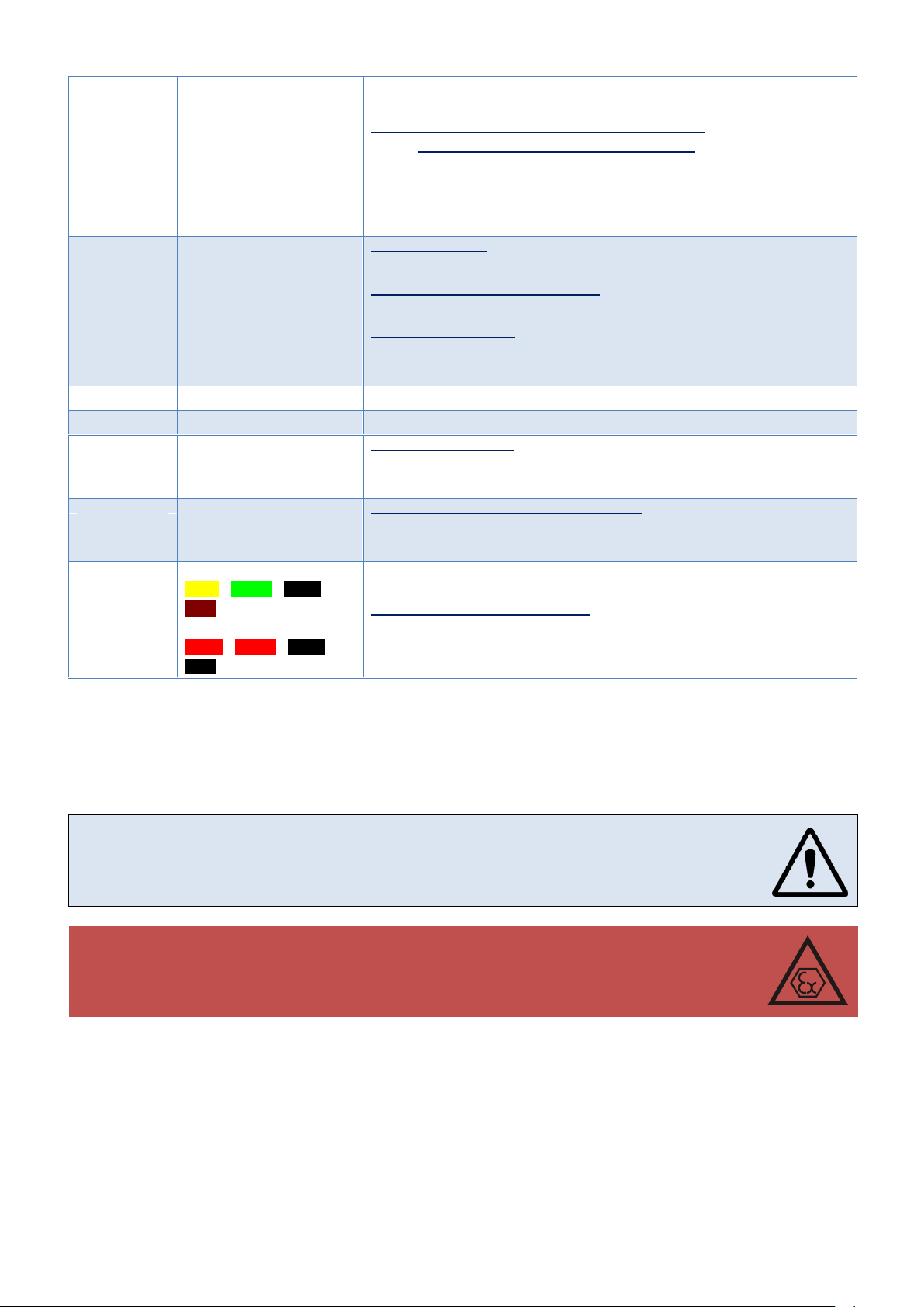
COMMON S.A. OPERATING INSTRUCTION CMK-03
OUTx
OUT1-1 , OUT1-2
(bipolar)
OUT2-1 , OUT2-2
(bipolar)
OUT3-1 , OUT3-2
(bipolar)
OUT4-1 , OUT4-2
(bipolar)
clamps „OUT1-1”–„OUT1-2”, „OUT2-1”–„OUT2-2”,
„OUT3-1”–„OUT3-2”, „OUT4-1”–„OUT4-2”
Uo=5,88V , Io=6mA , Po=9mW, Lo=50mH, Co=100μF, Li~0, Ci=0,6uF
Ui=10V, Ii=0,3A, Pi=1,1W
ExtCPC
V+, GND, A, B
clamps „A” – „B”
Uo=5,88V, Io=62mA, Po=45mW, Lo=50mH, Co=100μF, Li~0, Ci~0
clamps „A” – „GND”, „B” – „GND”
Uo=5,88V, Io=124mA, Po=91mW, Lo=10mH, Co=100μF, Li~0, Ci~0
clamps „V+” – „GND”
Uo=5,88V , Io=0,74A , Po=0,8W (summary power output of all clamps on
ExtCPC), Li~0, Ci~0, Lo=500μH, Co=100μF
HF
HF+, HF-
Uo=12,6V, Io=17mA, Po=54mW, Lo=50mH, Co=7μF
ENC
ENC+, ENC-
Uo=10,5V, Io=15mA, Po=38mW, Lo=50mH, Co=16μF
LF
LF+ , LF-
clamps „LF+” – „LF-”
Uo=10V, Io=15mA, Po=25mW, Lo=50mH, Co=16μF
Ui=10V, Ii=30mA, Pi=64mW
LFb
LFc
LFb+ , LFbLFc+ , LFc-
clamps „LFb+” – „LFb-”, „LFc+” – „LFc-”
Uo=10V, Io=2mA, Po=4mW, Lo=20mH, Co=16μF
Ui=10V, Ii=30mA, Pi=64mW
PT1000
clamps and cables colors:
PT-I+, PT-U+, PT-U-,,
PT-I-
lub
PT-I+, PT-U+, PT-U-,,
PT-I-
clamps PT-I+, PT-I-, PT-U+, PT-U- (between any of clamps)
Uo=5,88V, Io=54mA, Po=79mW Lo=50mH Co=63μF
The CMK-03 can be installed and operate in explosion hazard zone 1 or 2. The device can
cooperate with the intrinsically safe circuits on the security level “ia” or “ib”. The subgroup
conformity of the potentially gas mixture has to be maintained with the subgroup of device
circuits (IIA or IIB) and temperature T4 class.
The CMK-03 can be connect to the intrinsically safe circuits of other devices, only accordingly to the safety rules of usage which are contained in the certificates and manufacturer
instructions of this devices. The conformity of the intrinsically safe parameters has to be
maintained for the connected devices.
5 Assembly and installation
It is absolutely necessary to follow the recommendations of this operating instruction by the installation and
connection of the CMK-03. The device should be used according to the regulation and rules concerning antiexplosion safety.
19
Page 20
COMMON S.A. OPERATING INSTRUCTION CMK-03
(V+, GND) pins of the external power supply
A (D+), B (D-) pins of data transmission from port RS-GAZ2
(485 in execution EX)
FRONT VIEW OF MALE SOCKET
ON THE HOUSING
keyboard
grounding clamp
COM1 TUCHEL port
sealing clamp
OPTO-GAZ port
cable glands
P2 pressure
converter
p1 pressure converter
cable gland of the
thermometer
5.1 Connectors and outputs
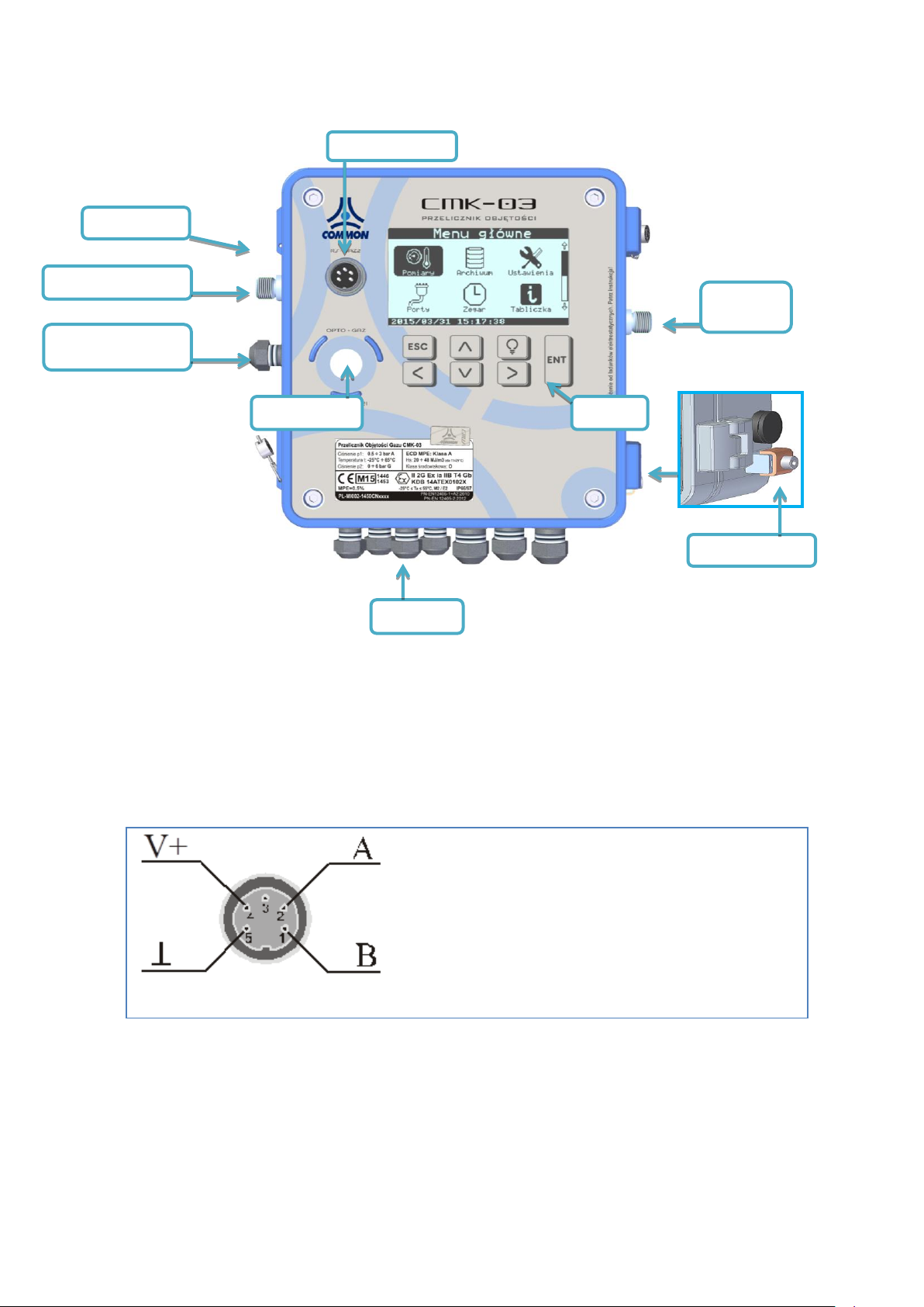
Figure 5.1 The sockets positions
5.1.1 The TUCHEL port on the housing
The 5 pins TUCHEL connector is placed on the housing. The port enables to connect the power supply and to
transmit the data by using COM1 port. The pins designation is described in Figure 5.2.
It is recommended to used CZAK-03 barrier to connect the power supply to the CMK-03. The CZAK-03 is manufactured by COMMON S.A. (see Table 2.1 Additional Accessories).
Figure 5.2 The TUCHEL connector -— “male” type socket, 5 pins, C091D type
20
Page 21
COMMON S.A. OPERATING INSTRUCTION CMK-03
WARNING!
It is obligatory to connect correctly the intrinsically safe circuits of the device. It is not
allowed to connect to the CMK-03 clamps any external devices with undefined purpose.
For example: the connection between the output of external power supply
(V+,GDN,A,B) with the ExtCPC output of the CPC-03 external converter may occurs
permanent device damage and loss of intrinsically safe parameters.
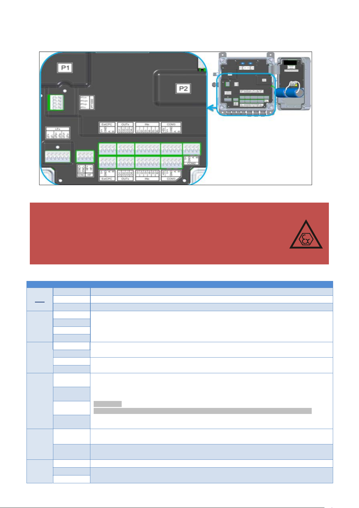
CABLE CONNECTORS
LFx
LF+, LF-
input of the LF pulse from gas meter index head
LFb+, LFb-
input of the control circuit from gas meter index head (LFbreak)
LFc+ LFc-
input of the LFc pulse from gas meter index head (from 2nd pulse transmitter, control type)
PT1000
PT-I+
thermometer connection clamps (details – part 5.6)
PT-U+
PT-U-
PT-I-
ExtCPC
V+
power supply outputs for an external CPC-03 pressure converter (details – part 5.6)
GDN
A
serial transmission port, to the external CPC-03 pressure converter (details – part 5.6)
B
OUTx
OUT11,
OUT1
2
control outputs OC (open collector)
bipolar outputs – polarity insignificant
WARNING!
pair connected wires (OUT11, OUT12) (OUT21, OUT22) (OUT31, OUT32) (OUT41, OUT42)
OUT21,
OUT22
OUT31,
OUT32
OUT41,
OUT42
INx
IN(14)+
IN(14)-
signaling double-state inputs (contact type)
IN(56)+
IN(56)-
signaling double-state inputs (contact type) or inputs in the NAMUR standard (configurable)
COM2,
COM3
+8V
supply voltage input for the NAMUR sensors (only COM3 port)
V+
external supply input for the RS-GAZ2 interface
GND
5.1.2 Internal clamps
The clamps are dedicated to the connection of the signals and external devices.
Figure 5.3 connectors positions – diagram
Table 5.1 Description of the CMK-03 connectors
21
Page 22

COMMON S.A. OPERATING INSTRUCTION CMK-03
A
serial transmission signals of the RS-GAZ2 port
B
The CMK-03 is constructed as an intrinsically safe device. The all terminal and ports are intrinsically safe circuits.
The general requirements for the multi-wire cable which are dedicated to the CMK-03 intrinsically safe
circuits:
permanent installation, protected against the mechanical damages
operating temperature range of the cables should be proper in relation to the temperature on the installa-
tion point
minimum, radial thickness of the insulation for every wire of the cable should be not less than 0.2 mm
dielectric strength of the “wire — ground” insulation — minimum 500 V AC (rms),
dielectric strength of the “wire — wire” insulation — minimum 1000V AC (rms),
wires diameter in the multi-wire cable — minimum 0,1 mm,
the ends of the multi-wires cable need to be protected to avoid the separation of the internal twisted pairs
wires. In this case the soldering process is not enough and the ends should be protected by using the
sleeves.
unused wire in the areas with the explosion hazard should be connected to the ground or isolated
by the connection to the terminal strips. The isolation tape is not allowed.
The all cable glands are in EMC execution and are adjusted to connection of the cable shields
in their entering place.
The intrinsically safe cables should be marked. In case of marking with the color it should be used light
blue color.
* clamps symbols A and B are also marked accordingly as D+ and D–
5.2 Cables of the intrinsically safe circuits
5.2.1 Requirements concerning the cables
The multi-wires cables of the intrinsically safe circuit and the method of their installation and connection in the
areas with the explosion hazard must be accordant to the requirements of the EN 60079-14 standard. There is
acceptable to use the cables A Type or B Type in the accordance with the paragraph 12.2.2 of the mentioned
standard.
If the wiring is outside of the explosion hazard area and it is need to connect intrinsically safe cables together with
the normal cables (intrinsically safety no required), the cables should be separated accordingly to the EN 6007914 standard.
5.2.2 Parameters and types of the connection cables
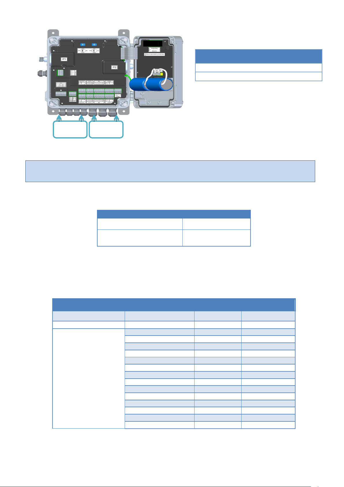
The M12 and M16 cable grommets enter the connection cables to the CMK-03 housing. The cable are connected
to the proper clamps (Figure 5.3).
In the CMK-03 there are two types of the cable glands: M12 and M16 — a ranges of the cable glands diameter
are listed in the Table below.
22
Page 23
COMMON S.A. OPERATING INSTRUCTION CMK-03
The unused cable glands should be covered by using a cylindrical elements which are made from the hard
or elastic material with the proper dimension. The gland nuts should be tighten up.
RANGES OF CABLES WIRE CROSS-SECTION
one-wire cable
0,20 1,5 mm2
cord cable with pressed connector sleeve with a collar
0,14 1,5 mm2
CABLE MAXIMUM LENGTH
cable type
cross-section
load
maximum length
LFx, ExtCPC
Dowolny z zakresu
-
<10m
COM1, COM2, COM3,
OUTx, INx,
1,5mm2
standard
750m
1,5mm2
full
125m
1mm2
standard
500m
1mm2
full
80m
0,75mm2
standard
370m
0,75mm2
full
60m
0,5mm2
standard
250m
0,5mm2
full
40m
0,34mm2
standard
170m
0,34mm2
full
28m
0,25mm2
standard
125m
0,25mm2
full
20m
0,14mm2
standard
70m
0,14mm2
full
10m
DIAMETER OF THE CABLE GLANDS
M12
4,5 6mm
M16
6,5 8mm
cable gland
4x M12
cable gland
3x M16
Figure.5.4 The cables entering to the housing, the dimensions of cable glands M12, M16
The cross sections of the cable wires is presented in the Table 5.2.
Table 5.2 The ranges of wire cross section of the cable wires
The maximum lengths of cables for a individual circuits are presented in the Table 5.3. The values are defined
regarding to:
the voltage decrease of cable resistance
the output of rated voltage from CZAK-03 power supply unit.
Table 5.3 Maximum cable length
23
Page 24
COMMON S.A. OPERATING INSTRUCTION CMK-03
The inductance and the electrical capacity of the cables with defined length must be taken under
consideration in the analysis of the conformity of the intrinsically safe parameters for connected devices.
TYPES OF THE SHIELDED CABLES
circuit type
cable type
LFx, ExtCPC, OUTx, INx, COM1
Use only shielded cables e.g. LIYCY
COM2, COM3
Shielded cables e.g. LIYCY or unshielded cables e.g. LIYY
UNSHIELDED CABLE
cable gland J-Type
SHIELDED CABLE
cable gland A-Type
8mm
8-10mm
65mm
65mm
8-10mm
1
3
2
4
2
1
1
4
2
5
2
1
where:
standard load means that CMK-03 is operating with active: LCD, LCD backlight, unit uC, measurement of
T and P and active transmission on one of the COM ports
full load means that CMK-03 is operating with the active options mentioned above and additionally with the
activated read function from the Encoder and from the two external CPC-03 converters (connected to the
extCPC port).
The examples of the cable are presented in the Table 5.4.
Table 5.4 Types of the shielded cables
There is important to use the cables which are dedicated to conditions on the installation point (the earth cables
or the outdoor cables).
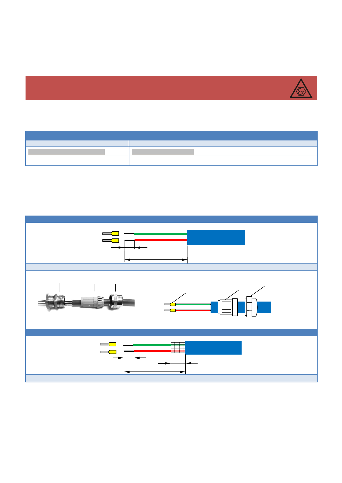
The cord cables (multi-wire) must be ended with the wire sleeves with an insulated collar. The sleeve should be
pressed on the all length. The preparation method of the cables is presented in the Table 5.5.
Table 5.5 Method of the cable preparation
24
Page 25
COMMON S.A. OPERATING INSTRUCTION CMK-03
2
1 53
1
5
6
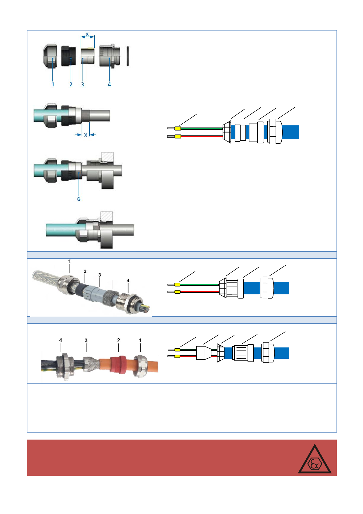
cable gland J-Type
cable gland P-Type (yellow elastomer)
LEGEND:
1. gland nut
2. sealing elastomer
3. sealing element which presses the cable shield
4. gland inlet screwed into the CMK-03 housing
5. sleeve
6. cable shield
WARNING!
The cable shields should be connected to the CMK-03 housing only on the grounded
side by using the cable glands. The shielded cables can not create loops, closing points
with different potentials, where could be flow equalizing currents.
1
3
5
6
6
6
1
2 3 5
5 3 2
1
6
5 5 1
25
Page 26
COMMON S.A. OPERATING INSTRUCTION CMK-03
WARNING!
The housing ‘IP’ protection level will be preserved only if:
will be used appropriate diameters of the connection cables or the covers
cables grommets will be proper tightened,
gasket will be in proper position
housing cover will be tightened correctly
WARNING! The CMK-03 housing must be grounded
WARNING!
The equipotentiality of the housing grounding point must be assure with:
the connection place of the pulse pipe to the gas meter or the gas line.
the thermometer installation place
the external CPC-03e converter installation place
5.3 The CMK-03 grounding
The grounding methods of the CMK-03 housing:
1. Installation bolts in the housing corners
The metal handles (CMK-03 installation sets) should be tightened to the mounting holes of the housing and
next the converter should be tighten by using them to grounded metal elements of the installation
2. Ground clamp connection
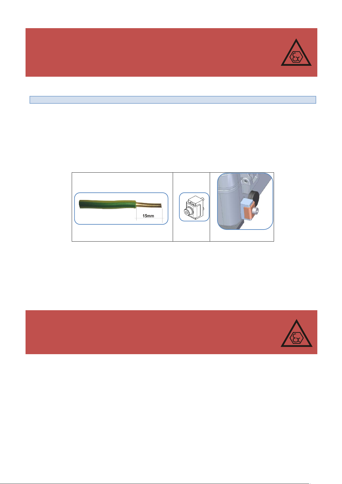
The CMK-03 effective ground connection can be assure by using the ground clamp, which is located on the
side of housing. There can be connected a single wire or multi-wire cable with cross-section up to 4mm.
The clamp is tightened with a cylindrical bolt, key size 3mm.
Figure 5.5 earth connection clamp
The additional grounding methods of the housing, which can not occur as only one earth connection are listed
below:
1. pressure converter pipe (located on the housing) is mostly connected via a steel pulse pipe with the pressure measurement terminal of the gas meter or piping.
2. thermometers steel pipe is electrical connected via cable shield with device housing.
3. housing of the CPC-03 External Pressure Converter is connected via cable shield with device housing.
26
Page 27
COMMON S.A. OPERATING INSTRUCTION CMK-03
PIPE AND CABLE LENGTH OF THERMOMETER
thermometer pipe length
cable lengths
45 mm
75 mm
95 mm
105 mm
120 mm
130 mm
140 mm
160 mm-standard
180 mm
200 mm
220 mm
245 mm
1,2 m
2,5 m + standard
4,0 m
5,0 m
6,0 m
8,0 m
9,9 m
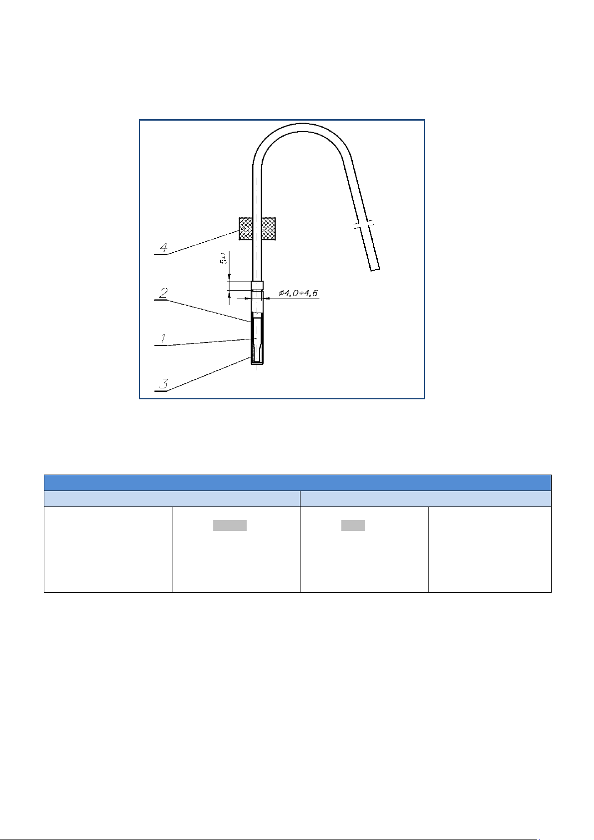
1. thermometer probe with cable
2. thermometer frame
3. thermal conductive paste
4. rubber insert
5.4 Connection of the temperature sensor
The CMK-03 is equipped in the platinum temperature sensor (PT 1000 Class 2/3A) CTA4 Type, manufactured by
COMMON S.A. The sensor allows for the measurement and registration of the gas temperature in range -25°C
+65°C.
Figure 5.6 The CTA4 thermometer manufactured by COMMON S.A.
The length of the thermometer pipe and the cable are presented in the Table 5.6. The maximum length of the
thermometer cable is 10 meters. The method of order is described in the Table 4.1 (code 5).
Table 5.6 Method of the cable preparation
The thermometer pipe can have electrical contact with installation of the gas line, that why there is necessary to
follow according to guidelines described in part 5.3.
5.4.1 Thermometer connection to the CMK-03 clamps.
The thermometer cables are factory connected, to clamps of the port marked as PT 1000 inside the housing. The
thermometer name plate is placed on the thermometers cable. The thermometer serial number is recorded in the
CMK-03 memory on the production phase and it is displayed on the LCD screen. The thermometer is formal
combined and identified with model of CMK-03.
27
Page 28
COMMON S.A. OPERATING INSTRUCTION CMK-03
The breakdown of the manufacturers seal from the PT1000 clamps cover, does not affect
on the metrological features of instrument. It gives possibility to check periodically the
correctness of working thermometer and correctness of the input data line. The clamps
cover of the PT1000 must be properly placed and sealed with a users seal after every service activities. From this time the user is responsible for the correct connection of the
thermometer.
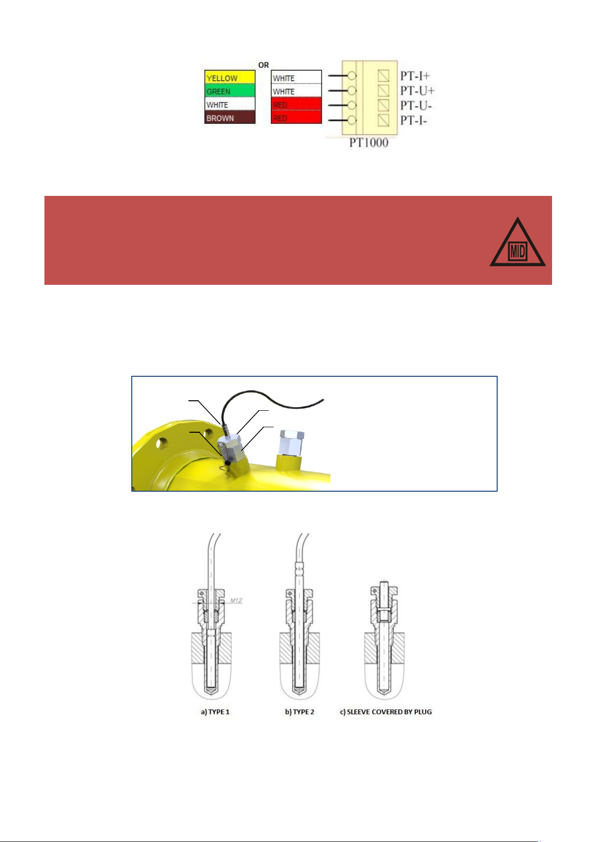
1. M12 tightening nut
2. thermowell
3. thermometer probe
4. seal
Figure 5.7 Cables connection of the CTA4 thermometer.
The terminal clamps are protected against the interference with the factory sealed cover.
5.4.2 Thermometer connection to the installation.
The thermometer is placed in the thermowell, which is located in the piping or gas meter. It is sealed with a rubber
gasket and secured with a tightening nut (M12 thread) (see Table 2.1, Additional Accessories).
The tightening nut is adjusted to the sealing (there is a hole for a sealing cord). The example of thermometer installation in the piping is presented in the Figure 5.8.
Figure 5.8 Thermometer assembly in piping
The Figure 5.9 presents the thermometer placement in the body of gas meter.
Figure 5.9 The PT1000 thermo probes assembled in the body of CGT-02 Turbine Gas Meter
manufactured by COMMON S.A.
28
Page 29
COMMON S.A. OPERATING INSTRUCTION CMK-03
example position of CKMT three way valve
P1
P2
5.5 Connection of the P1 and P2 pressure sensors
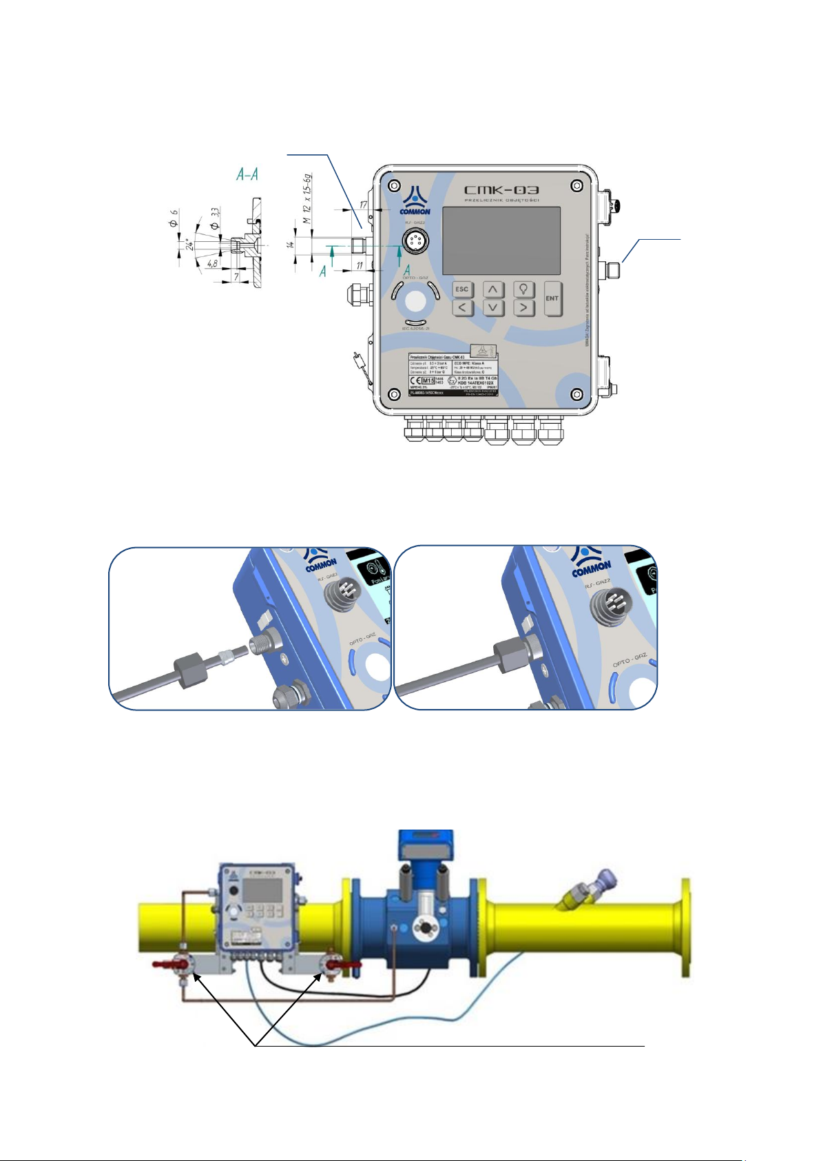
The CMK-03 has maximum two built-in pressure converters (P1 and P2 in the Figure 5.10). The connection pipe
of the converter has a threat M12x1,5 in the typical application. The available variants and the pressure ranges
are listed in the Table 4.5.
Figure 5.10 The construction of the M12x1,5 pressure connection pipe
The measuring pressure pipe, should be connected to the pressure sensor by using the pulse pipe. The connection method of the pulse pipe from the converter side is presented in the Figure 5.11 (M12x5 nut, the tightening
ring, the pulse pipe — all items are available as an additional accessories — see Table 2.1).
Figure 5.11 The connection of the pressure measurement to the P1 pressure sensor
There is a CKMT three way between the point of pressure measurement and the measuring converter valve in
the typical application of the piping (see Table 2.1). The CKMT three way valve is manufactured by COMMON
S.A. This instrument allows for the inspections and checking of the sensors. The example of the installation for
the pressure connection is presented in the Figure 5.12.
Figure 5.12 The example of pressure connection by using the CKMT valve manufactured by COMMON S.A.
29
Page 30
COMMON S.A. OPERATING INSTRUCTION CMK-03
WARNING!
The connection of the pressure sensors is an electrical contact between the housing and piping. Such
connection can not be understood as the “grounding connection”. The grounding methods are described in the part 5.3.
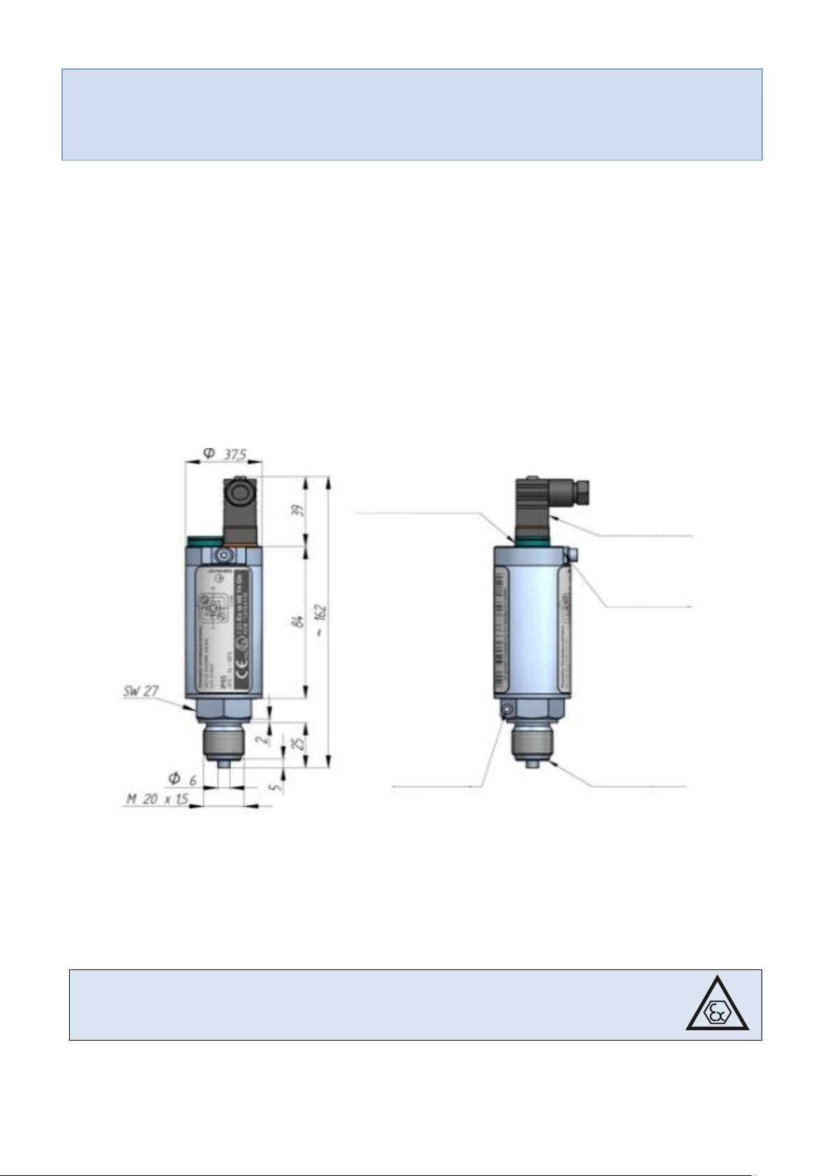
The CPC-03 can be installed and operate in explosion hazard zone 1 or 2. The subgroup
conformity of the potentially gas mixture has to be maintained with the subgroup of device circuits (IIA or IIB) and temperature T4 class.
pressure equalizing
element
seal cord
opening
HIRSCHMANN
connector
grounding clamp
flat gasket
5.6 Connection of the external CPC-03 pressure converter
The CMK-03 allows for a reading and registration of the pressure values from two CPC-03 external, digital converters manufactured by COMMON S.A. (Table 2.1. Additional Accessories). The technical data of the CPC-03
converter are available in the operating instruction.
5.6.1 Mechanical installation of the CPC-03
The CPC-03 converter is dedicated to connect to the processing socket with a defined type. Typically there is a
M20x1,5 manometrical socket. The other types are available on the special order. The installation of CPC-03
requires the proper sealing.
The CPC-03 ground connection is achieved when the instrument is threaded to the grounded part of the piping,
gas meter etc. If there is no possibility to assure connection with the ground in such way, the CPC-03 housing
should be grounded by using a cable with the proper cross-section (minimum 4mm2), tightened to the marked
ground clamp on the side of housing (the detailed information are contained in the CPC-03 operating instruction).
Figure 5.13 CPC-03 converter - mechanical installation
5.6.2 CPC-03 electrical connection
The power supply and data transmission are assured by using the ExtCPC clamps of the converter.
The converters are adjusted to operation in the areas of explosion hazard, according to the marking
about explosion-proof construction.
30
Page 31
COMMON S.A. OPERATING INSTRUCTION CMK-03
WARNING!
The CPC-03 converter should be connected by using the shielded cables. The cable shields should be
connected from the converter side. The preparation method of the cables is presented in the Table
5.5.
WARNING!
It is obligatory to connect correctly the intrinsically safe circuits of the device. It is not
allowed to connect to the CMK-03 clamps any external devices with undefined purpose.
For example: the connection of external power supply output (V+,GDN,A,B) with
ExtCPC output of the CPC-03 external converter may occur permanent damage and
loss of the intrinsically safe parameters.
WARNING!
The proper cooperation between the CPC-03 external converter and the CMK-03 is possible with firmware version CPC-03 no. v. 13.11.27.08.
The CPC-03 with the older firmware will not working correctly with the CMK-03.
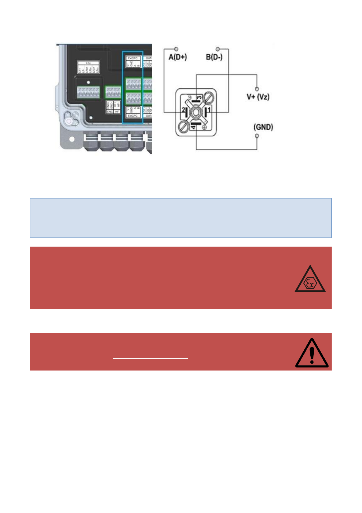
The connections between the converter port and converter clamps are presented in the Figure 5.14.
Figure 5.14 The connections of the CPC-03 pressure sensor to the CMK-03 converter clamps .
The clamps of the ExtCPC ports are doubled in the both terminal strips. This allows for easy, parallel connection
for two cables to the electrical same ExtCPC port.
The operating configuration is described in the part 11.2.7.
The firmware version of the CPC-03 can be checked by reading the name plate of CPC-03 in the Gaz-Modem2/3
protocol. This information is available as a “wersja prog” parameter in the DP Table. There is also possible to
check the name plate by using CCTool program — after connection the firmware version will be displayed in the
top part of the screen.
5.7 Connection of the LF input to the gas meter
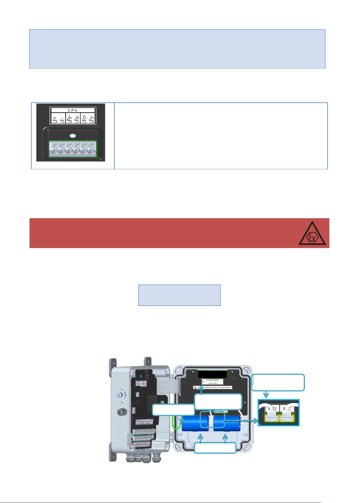
The cable which provides pulses form the gas meter (carrying information about quantums of the measured volume) should be connected to the LF+ and LF- clamps of the LFx port.
The polarization is not significant in working mode with the reed-relay pulses transmitter. The polarization should
be kept, in working mode with the electronic transmitter (e.g. Wiegand) with the polar OC output.
31
Page 32
COMMON S.A. OPERATING INSTRUCTION CMK-03
WARNING!
The LF+ and LF- clamps should be connected only by using the shielded cables with the maximum
length to 10 meters (cable selection – see Table 5.3). The cables shields should be connected from
the side of converter. The preparation method of the cables is presented in the Table 5.5.
LF+, LF- — the input of LF pulses from the gas meter index head
LFb+, LFb — the control input LFb from the gas meter index head
(LFbreak)
LFc+ LFc — the input of the LFc pulses from the gas meter index head
(e.g. second, control LF transmitter)
WARNING!
It is necessary to use the batteries according to the operating instruction. The batteries
used in the CMK-03 can be disconnect and connect in the explosion hazard zone.
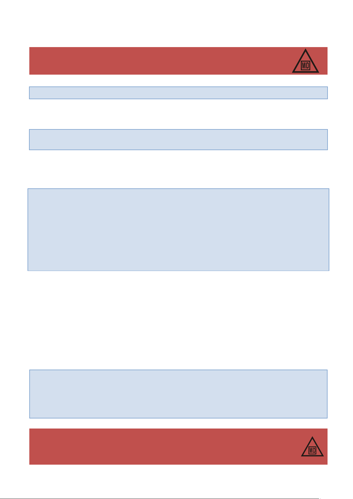
Battery type: BAT-03
Manufacturer: Common S.A.
LCD display
battery
main batteries
battery handle
angle connectors for
battery connection
It is allowed to keep connection between the LF cable shield with the plug of gas meter, by following conditions:
the shield should be disconnected (insulated) from the cable gland in the CMK-03
equal potential should be assure between the housing of the gas meter and the volume converter
5.8 Mechanical installation of the CMK-03
The installation methods are described in the Appendix 1 – “The mechanical installation methods of the CMK-03”.
5.9 Battery
5.9.1 Main batteries.
The CMK-03 main power supply is a battery pack “BAT-03” Type (there are two installed batteries) manufactured
by COMMON S.A. The batteries are marked as follow:
The battery pack is ended with a cable which has a connector with a protection against the polarization. The
placement method of the battery cable is free, but it should not cause a tension of the cables from plugs.
The batteries are connected to the internal sockets marked as BAT1 and BAT2. The device has the battery self
detect function what means that there is an automatically detection when battery is connected or disconnected.
The batteries are installed in the springy handles inside the housing cover (Figure 5.28).
Figure 5.28 The battery installation.
32
Page 33
COMMON S.A. OPERATING INSTRUCTION CMK-03
The replacement of the main battery BAT1 and BAT2 does not break the seals and the
metrological characteristic of the CMK-03.
The disconnection of the both main batteries does not cause a loss of the current and registered data.
By the CMK-03 external power supply all of the functions are using only the external power and the
main batteries are not in use.
The battery kit life-time is minimum 5 years in typical, defined working conditions which are defined as
follows:
lack of the external supply (V+, GND)
frequency LF = 2Hz
ta = - 25°C
p1 = max range value
t = min range value
frequency of the measurements “p1” and “t” every 30 s
p2…p4 – lack of converters
LCD service < 5 minutes / 24 h
battery type approved to the usage: SL-760 Xtra or TL-5903 manufactured by Tadiran
battery should be installed in a handle according to the polarization (+, - )
false polarization will not cause a damage of the device or of the battery, but as result will be im-
proper work of the LCD backlight
false battery connection will not cause a loss of the intrinsically safe parameters of the device
The replacement of the backlight battery, does not break the seals and the metrological
characteristic of the CMK-03.
The battery can be sealed with the factory seal or user seal after the replacement and after
the ending of guarantee time.
The batteries can be factory sealed or sealed by the user after the replacement and after ending of the guarantee
time.
The data are stored in a nonvolatile memory which does not require the power supply. The data saving is continuing till the voltage cut-off of the battery or the external power supply. There are saved all counters and data bases.
The CMK-03 calculates in the real time a level of the battery usage. If the estimated battery working life time
reaches the level lower than 10%, it will be registered an alerts in the bases: “Archive”, “MID Alarms”, and
“Events”. The alerts are presented on the LCD as a text: ”Battery <10%” and “Battery<10%(MID:133)”. In
such case it is necessary to replace the battery on new.
The battery status and the estimated life time are available on the LCD on one of the MID screens:
Etl — the number of working days till the battery discharging
Bat — the percentage battery status
This parameters are also available in the Gaz-Modem protocol.
5.9.2 Battery of the LCD backlight.
There is a separated AA size battery which supports the LCD backlight. The battery is installed in a handle under
the device cover (see Figure 5.28). The backlight helps to read the data and operate the display in weak illuminated places. The backlight does not use the energy from main batteries and does not reduce their working life
time. If the CMK-03 is working on the external power supply, the LCD backlight uses only this power source and
the LCD battery is not in usage.
33
Page 34
COMMON S.A. OPERATING INSTRUCTION CMK-03
The electrical intrinsically safe parameters – see part 4.33
The selection of cooperating devices must to fill the conditions listed in the Table 4.12 Condi-
tions of the conformity of the intrinsically safe parameters.
The method of cable selection is described in part:
5.2 “Cables for the intrinsically safe circuits”
WARNING!
The hazard of electrostatic charges. The front cover of the device (elevation, keyboard, display window) is made of the synthetic material where can be accumulated the electrostatic
charges. This surface may not be to rub with dry materials, so as not to cause the electrify
effect and danger of discharge!
The life time of the backlight battery is approximately 80 hours of constant summary work. This time period can
be shorter if the device will operate in the low temperatures, or there is a often, long usage of the backlight.
The battery operation time is approximately 2,5 year, if the LCD will work on the battery supply mode with active
backlight during 5 minutes per day (24h). The backlight battery is not covered by the guarantee.
5.10 Safe usage conditions
The CMK-03 converter should be used according to:
purpose with the guidelines indicated in the operating instruction
conditions included in the certificate KDB 14ATEX0102X
standards and rules concerning installation and intrinsically safe systems.
The connection between CMK-03 circuits (“ia” security level) with the other devices with “ib” security level implicates a creation of the system which is on the lower “ib” security level (including the CMK-03).
6 Gas volume conversion
6.1 Principle of the operation
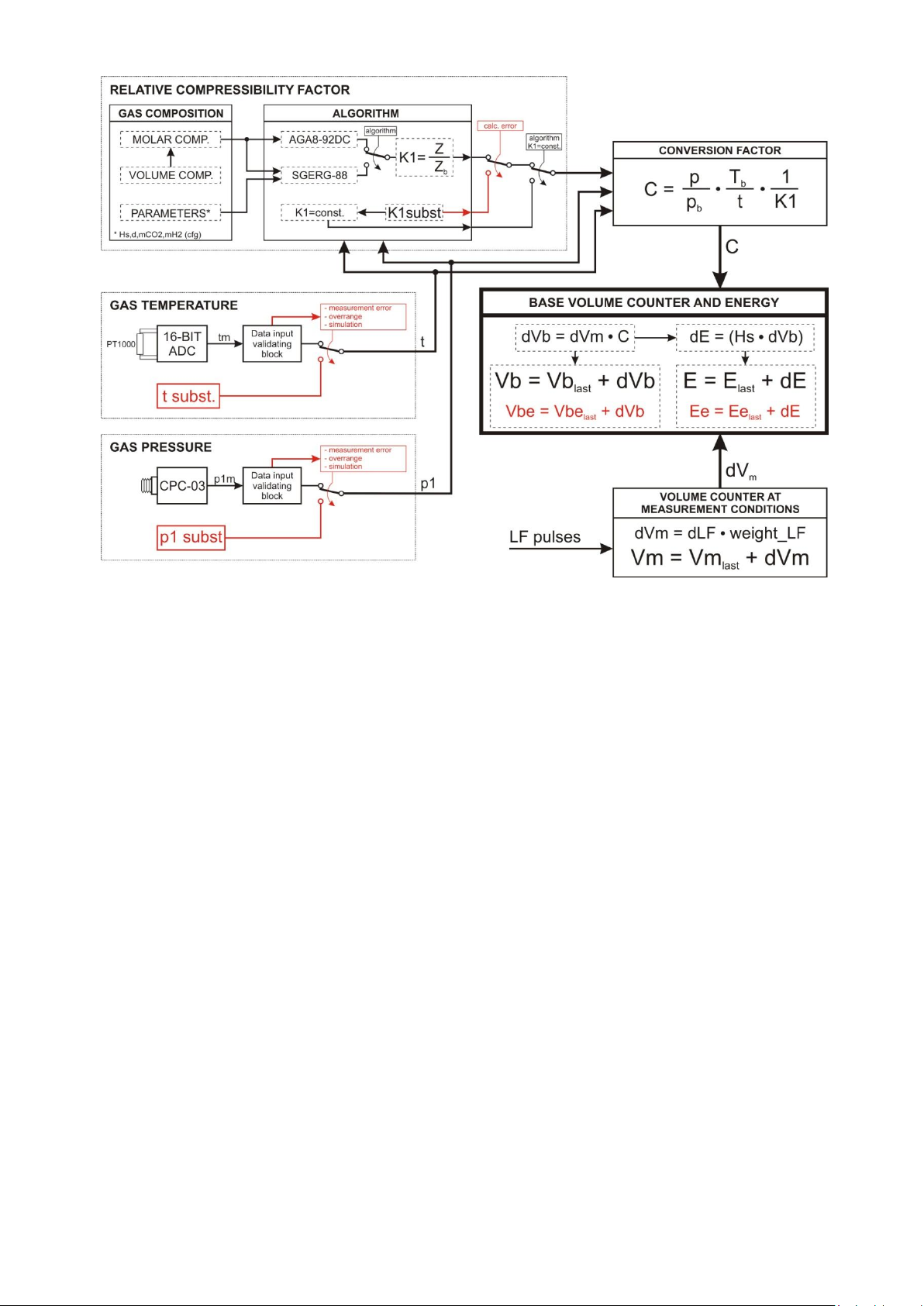
The CMK-03 converter sums the gas volume based on the LF pulses in measuring conditions Vm and also
makes conversion of the gas to the basic conditions Vb based on:
measured value of the absolute gas pressure p1,
measured value of the gas temperature t,
programmed gas composition or gas chemical and physical parameters,
The volume increase of gas in the measuring conditions is calculated as the product of the total number of dLF
pulses and their value “waga_LF”. In the next step the volume increase of gas is summed to the main counter:
where:
waga_LF – quantum of the volume increase in measuring conditions in relation to one LF pulse
dLF – pulses number increase
dV
– volume increase in the measuring conditions,
m
34
Page 35

COMMON S.A. OPERATING INSTRUCTION CMK-03
V
– volume counter value in the previous state.
mpop
The calculations of proper parameters in basic conditions are made in case of:
changing the gas composition/parameters
changing the reference temperature Tb
changing the reference pressure pb
initialization the converting module/device
The measurement of the gas temperature and gas pressure, the calculation of the parameters in the measuring
condition and the designation of the C, K1, Z coefficients are made for every 30 seconds on the battery supply
and for every 1 second on the external power supply working mode.
Additional:
if there is no pulses from the gas meter during time longer than period of the measurements (30 sec. or 1
sec.), a mean value of the “C” coefficient is calculated for time-period which was without pulses.
if first pulse will come in defined time interval this causes:
the pulse is counted to the Vb/Vbe counter with mean value of the C coefficient correction.
the mean value of the C is initialized by the current value of Cc coefficient.
every next pulse is summed with new value of the C coefficient in defined time interval.
This rule of operating provides a higher, dynamical precision of the calculation, in the situation when the gas parameters are changing between LF pulses from the gas meter (a small flows).
The all counters (Vm, Vb, Vbe, E, Ee) are updated for every incoming LF pulse and are refreshed on the display
in every pulse or in every 1 second, regardless of the type of power supply mode (battery or external).
The volume increase in the basic conditions is calculated as product of the dVm counter increase in the measuring conditions and the C correction coefficient, and then is summed to the main counter:
where:
C – coefficient of the volume conversion
dV
– volume increase in the basic conditions
b
V
– value of the volume counter in previous state
bpop
The Zb compressibility coefficient in the basic conditions and Z compressibility coefficient in the measuring conditions are determinate by one of the available calculating methods which is implemented in the converter.
CONVERSION PTZ – for algorithms: SGERG-88 and AGA8-92DC.
The C correction coefficient is calculated on the base of formula:
CONVERSION PT – for constant, programmable value of K1 coefficient
where:
K1 – relative compressibility coefficient
35
Page 36
COMMON S.A. OPERATING INSTRUCTION CMK-03
Figure 6.1 CMK-03 operating rules — flowchart
6.2 Algorithms
The CMK-03 converter has implemented a calculating methods as follows:
SGERG-88
AGA8-92DC
“K1=const”
For the SGERG-88 method there are incoming data (which define gas mixture) as follows:
detailed molar gas composition (37 component), or
detailed volumetric gas composition (37 component), or
gas parameters (Hs, d, CO2 (molar), H2 (molar)).
For the AGA8-92DC method there are incoming data (which define gas mixture) as follows:
detailed molar gas composition (21 component), or
detailed volumetric gas composition (21 component)
For the “K1=const” method there is no necessary to define the gas composition. The K1 coefficient is equal with
the Z/Zb ratio. The conception of this method is to use the CMK-03 on a bio-gas station or others stations where
the gas components exceed applicability ranges of the implemented calculating methods in the converter, and
operating pressure does not exceed determinate value.
If there is known a gas specification, there is possible to define the relative compressibility coefficient based by
means of:
algorithm implemented in the converter (if it will be a solution),
different proper calculating method,
built-in “biogas calculator” in the CCTool software.
The such defined value of the relative compressibility coefficient, may be use to the volume correction.
The “K1=const” method has a limits which were defined to restrict the calculating error to the value not bigger
than 0,25%. In case of:
36
Page 37

COMMON S.A. OPERATING INSTRUCTION CMK-03
K1 = 1, gas pressure has to be lower than 1.5 bars abs.
K1 = const. but K1 ≠1 , gas pressure has to be lower than 11 bars abs.
It is necessary to define the permissible measuring limits of gas and temperature, to observe the error caused by
K1 constant value in relation to the changing values of the temperature and pressure. The observed error should
not be greater than 0,25%.
To define the mentioned limits should be used the dedicated parameters: Limit t for K1=const<>1 and Limit p1
for K1=const<>1 (available in the CCTool configuration software).
6.3 Bio gas configuration
The CMK-03 converter is a MID device. The algorithms such as AGA8 or SGERG-88 (approved according to
the standard) have a limits of the incoming parameters value. This limits do not allow to define a value of the
compressibility coefficient for gases and their mixtures which are out of range of the approved applicability. Accordingly to it, there is provided the programming option (MID – metrological controlled) of the constant relative
K1 compressibility coefficient.
The configuration on the bio gas working mode:
the K1 coefficient can be programmed on value K1=1, on a gas stations where operating pressure 1,5
bars abs and there are unknown details of the gas composition. It can be set by using LCD or CC Tool
software. Additionally the converter should contain the programmed value as follows:
correct Hs heat combustion value to the proper energy indication. The Hs heat combustion value os-
cillates typically for bio-gas in ranges 15…21MJ/m3 (4,1…5,8 kWh/m3).
correct d relative density value allows for proper calculation of the mass stream and W Wobby’s num-
ber.
the K1 coefficient values K1<> and additional measuring limits for pressure “p1” and temperature “t ” can
be determinate by using a “Bio-Gas Calculator” in the CCTool program on a gas stations where the operating pressure is on level 11 bars abs, and there are known the details or parameters of the gas composition. The determinate values should assure an error caused by p1 and t on the level not greater than +/0,25%. The Bio Gas Calculator designates also the value of Hs heat combustion and the value of d gas
relative density. There is also possible to enter this values manually.
The K1=const<>1 determination procedure by using the CCTool program:
1. connect with the device
2. select bookmark “Gas composition”
3. select “Bio gas calculator”
4. enter the gas composition or parameters
5. enter the average values of the gas pressure and gas temperature in measuring installation according to
the example as below:
if the temperature is in typical range from 20°C to 30°C, the temperature value should be set on 25°C
if the over-pressure range in the installation is from 60 to 140 mbar (6 to 14 kPa) the pressure value
should be set on 100mbar (10kPa) over the average atmospheric pressure e.g. 110 kPA abs.
6. select “Calculate K1”. It will be determine 3 values of the K1 coefficient.
a. K1 which is corresponding with the average values of p1 and t,
b. K1’ which is corresponding with the bottom pressure range and the top temperature range (conditions
for maximum value of the K1 coefficient)
c. K1’’ which is corresponding with the top pressure range and the bottom temperature range (conditions
for minimum value of the K1 coefficient)
If there is fulfilled condition: K1’<0,25% and K1’’<0.25% for the selected gas and initially set ranges of
the p1 and t, the converter can be programmed by using “set” button. After this operation there are set pa-
rameters as follows:
K1=const algorithm,
37
Page 38

COMMON S.A. OPERATING INSTRUCTION CMK-03
Examples of the ‘Bio-gases’ compositions (volume shares)
example 1
example 2
methane – CH4 51,89%
carbon dioxide – CO2 35,75%
nitrogen – N2 12,37%
oxygen – O2 0,01%\
heat of combustion – Hs 20,62 MJ/m3
5,727 kWh/m3
relative density – d 0,9420
gas temperature approx. 20 … 30°C
gas pressure approx. 60… 140mbar (6… 14kPa)
above atmospheric pressure
gas flow approx. 150m3/h
carbon dioxide – CO2 57,2%
methane – CH4 35,0%
hydrogen – H2 4,0%
hydrogen sulfide – H2S 3,0%
oxygen – O2 0,5%
nitrogen – N2 0,3%
gas composition (information),
gas parameter: Hs, d, mCO2,
calculated K1 value,
determined limits for t and p1
The set parameters should be sent (record) to the CMK-03.
There are deviations of the K1’ and K1’’ values for selected gas and initially set ranges of limits for p1 and t.
If those deviations are bigger than +/- 0,25% in comparison to the middle value of K1, the limits of p1 and t
should be narrow down till the values which correspond with the real conditions on the operating station or it
should be selected the mean values of p1 and t. The limits value which are suggested by the program are very
wide.
The t temperature is typically on level approx. 20°C or 30°C for a bio-gas but program assumes initially t value
from 10°C to +40°C. The limits are adjustable and can be set as they are on the real existing gas installation.
If the set limits will be to narrow, it can cause that the volume values will be counted in to the emergency counter
in case of the t crossing over the programmed limits.
If there are exist the designated gas parameters (Hs, d) mentioned in delivered gas specification, it is possible to
enter them manually.
The Hs heat of combustion value is presented in a different units (MJ/m3 or kWh/m3):
1 [MJ/m3] = 3,6 * 1 [kWh/m3]
1 [kWh/m3] = 1 [MJ/m3] / 3,6
Table 6.1 Examples of the ‘bio-gases’ compositions
7 The energy conversion
The energy conversion is based on the formula:
where:
E
dE – calculated energy increase
The energy increase calculation and the counter actualization are made for every LF pulse incoming from the gas
meter.
the numerical coefficient 3,6 which is a result of the units conversion:
Hs – heat combustion value included reference T1 temperature
dV
– the value of energy counter from the previous state
pop
– volume increase value in basic conditions
b
, where
b
38
Page 39
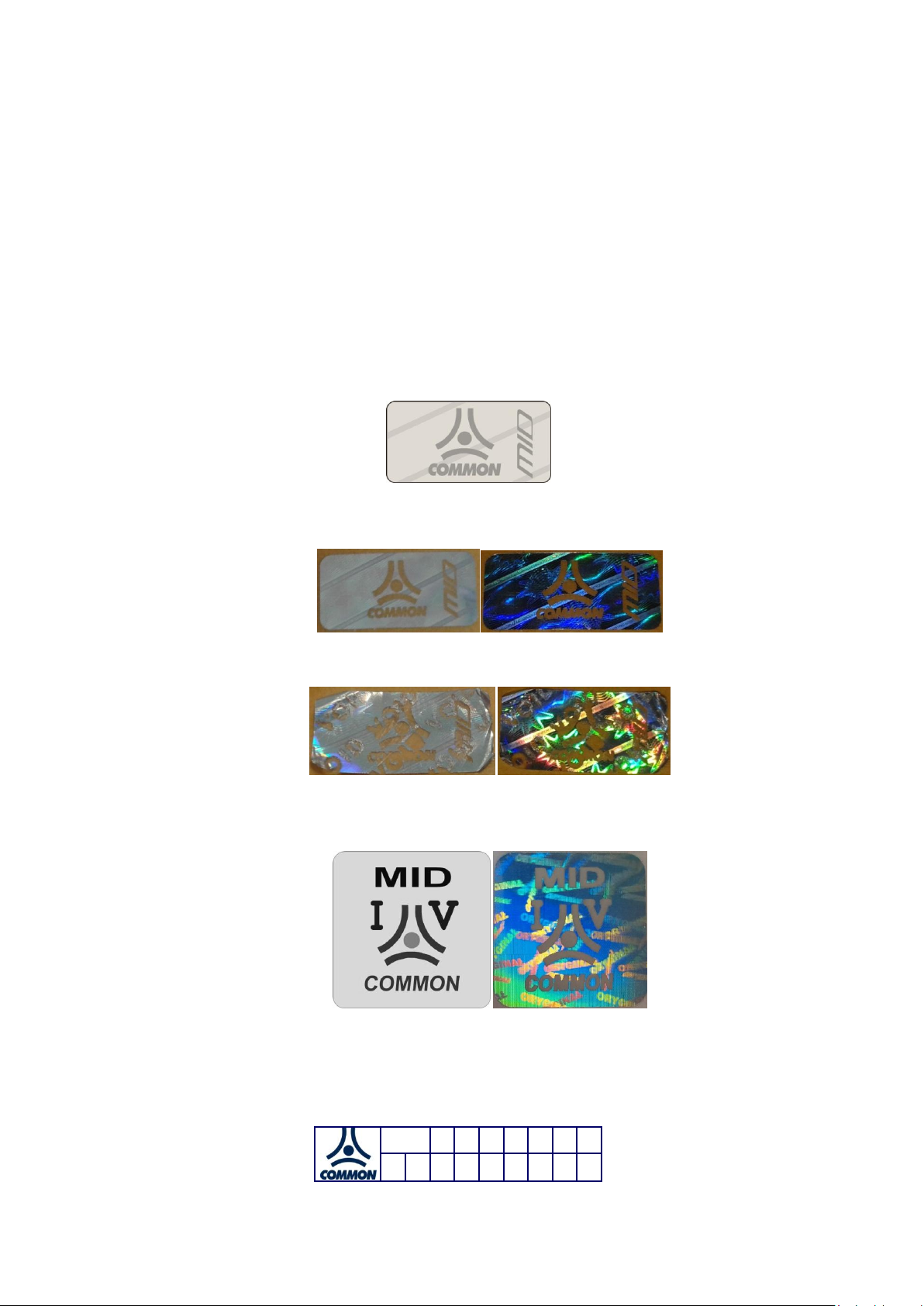
COMMON S.A. OPERATING INSTRUCTION CMK-03
15
0 1 2 3 4 5 0
1 2 3 4 5 6 7 8 9
The unit MJ/m3 is default for Hs parameter in the converter. The Hs value conversion per unit kWh/m3 is following:
1 MJ/m3 = 3,6 * 1 kWh/m
Important! The algorithms which calculate the value of Hs heat combustion, take into consider the T1 temperature
(parameter) as a reference temperature of the combustion process. The T1 parameter is typically equal 25°C
(298,15 K) and is configurable.
3
8 Metrological marking, protection seals, name plates
8.1 Metrological marks – Seal 1 and Mark IV
The unique type, self-adhesive labels are used as a metrological seals. The labels are made of the special,
holographic material with a laser burned mark according to the pattern presented below. Seals are highly adhesive, durable and resistant to environmental conditions. By the attempt of interference they remain permanent
mark – word “VOID” on the token off seals foil. There is impossible to place again once removed seal.
scale 2:1; real size: 10 x 20 mm
Figure 8.1 Pattern of the metrological marking
Figure 8.2 View of proper metrological mark
Figure 8.3 view of broken metrological mark
The marking label is placed on the front surface of device after the primary verification – see Figure 8.4
scale 2:1; real size: 20 x 20 mm
Figure 8.4 patter and view of primary verification marking
8.2 Manufacturer protective seals – Seal 2
The manufacturer protective seal is placed as a type of fragility seal.
scale 2:1; real size: 20 x 20 mm
Figure 8.5 Pattern of the manufacturer protective seal
39
Page 40
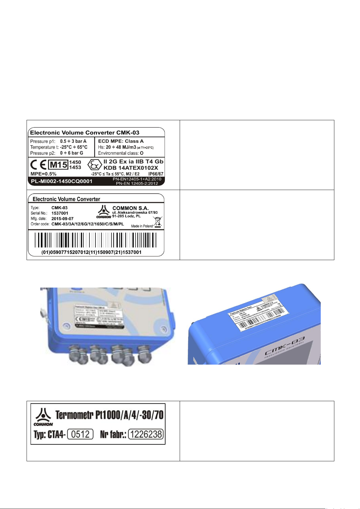
COMMON S.A. OPERATING INSTRUCTION CMK-03
Example of the “MID” metrological plate
The two last numbers which are located in a rectangle field
after M letter, identify the year of converter primary verification. In this case there is number ‘15’
The p1 and p2 pressure ranges are corresponding to the
version of execution
Example of the metrological plate with data and “KOD” bar
code
The fields such as: “serial number”, “date of production”,
“code of product” contain the information which identify
every unit of the CMK-03
The CTA4 thermometer name plate
The thermometer is metrological combined with the converter
in phase of the primary verification. The name plate is located on the cable.
The numbers which are printed after “CTA4” symbol, specify
the thermometer parameters according to the CODE(5).
It is possible to use equivalently manufacturer seals with a different, approved pattern.
8.3 User protective seals – Seal 3
The CMK-03 construction predicts the places dedicated for a user protective seals (see Figure 8.13). User is obligated to place the protective seals after device installation. They should be placed after control of the device mechanical installation and electrical connection what should be done accordingly to this operating instruction and
other safety rules.
8.4 Marking of name plate
The label pattern and the name plates are presented below:
The “MID” plate is placed on the device front and “KOD” plate on the top side. Plates are protected with the metrological marks (Fig 8.6 and Fig. 8.7).
Figure 8.6 MID plate – placement Figure 8.7 “KOD” plate - placement on housing
The plate position may be slightly different from presented above. The “KOD” plate may be placed on the front,
next to “MID” plate.
40
Page 41
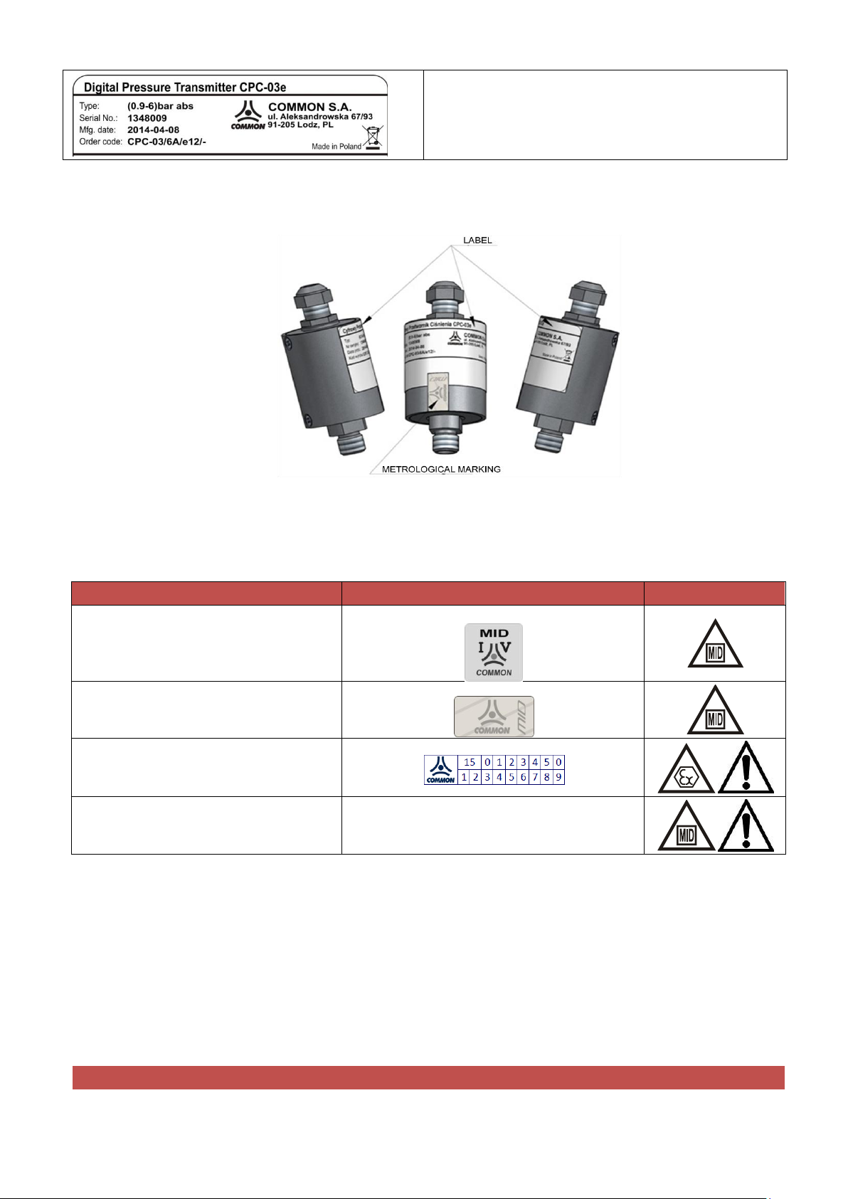
COMMON S.A. OPERATING INSTRUCTION CMK-03
The name plate of the CPC-03e p1 external converter
The CPC-03e pressure converter is metrological combined
with the CMK-03 in phase of the primary verification.
TYPE OF PROTECTION
SEALING SYMBOL
primary verification mark
(Initial Verification)
Mark I.V.
metrological protective mark
Plomba 1
manufacturer seal
Seal 2
user seal
Seal 3
Damage of any of the above protective marks results as follows:
Figure 8.9 The positioning and sealing of the CPC-03e name plate
8.5 Diagram of sealing inside instrument’s housing
The seals localization inside the CMK-03 housing is presented in the Figure 8.10.
There are three types of the mechanical protective marking.
The metrological marks are placed on the instrument after:
phase of primary verification
metrological certification according to approved type
admission to an accounting functions.
The manufacturer seals protect against an unauthorized access to the operating and maintenance areas of device.
The user seal should be placed on the device as a protection against access and interference into the measuring
signals or technological functions such as: LF signal input clamps, PT1000 temperature sensor input clamps, the
hosing closing place after finished installation, the pressure or temperature connection places.
41
Page 42

COMMON S.A. OPERATING INSTRUCTION CMK-03
- a loss of the credibility characteristic as a measuring–accounting instrument
- a loss of the manufacturer guarantee and intrinsically safe characteristic
- signal of the unauthorized interference in the measurement system
42
Page 43
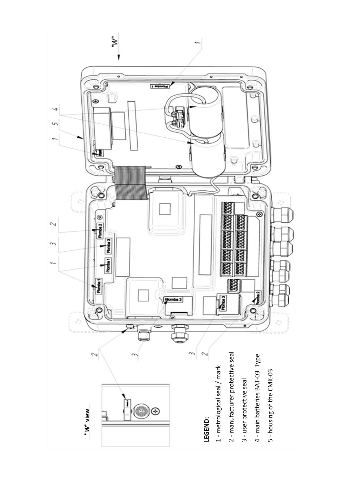
COMMON S.A. OPERATING INSTRUCTION CMK-03
Figure 8.11 The sealing inside the CMK-03 housing
43
Page 44
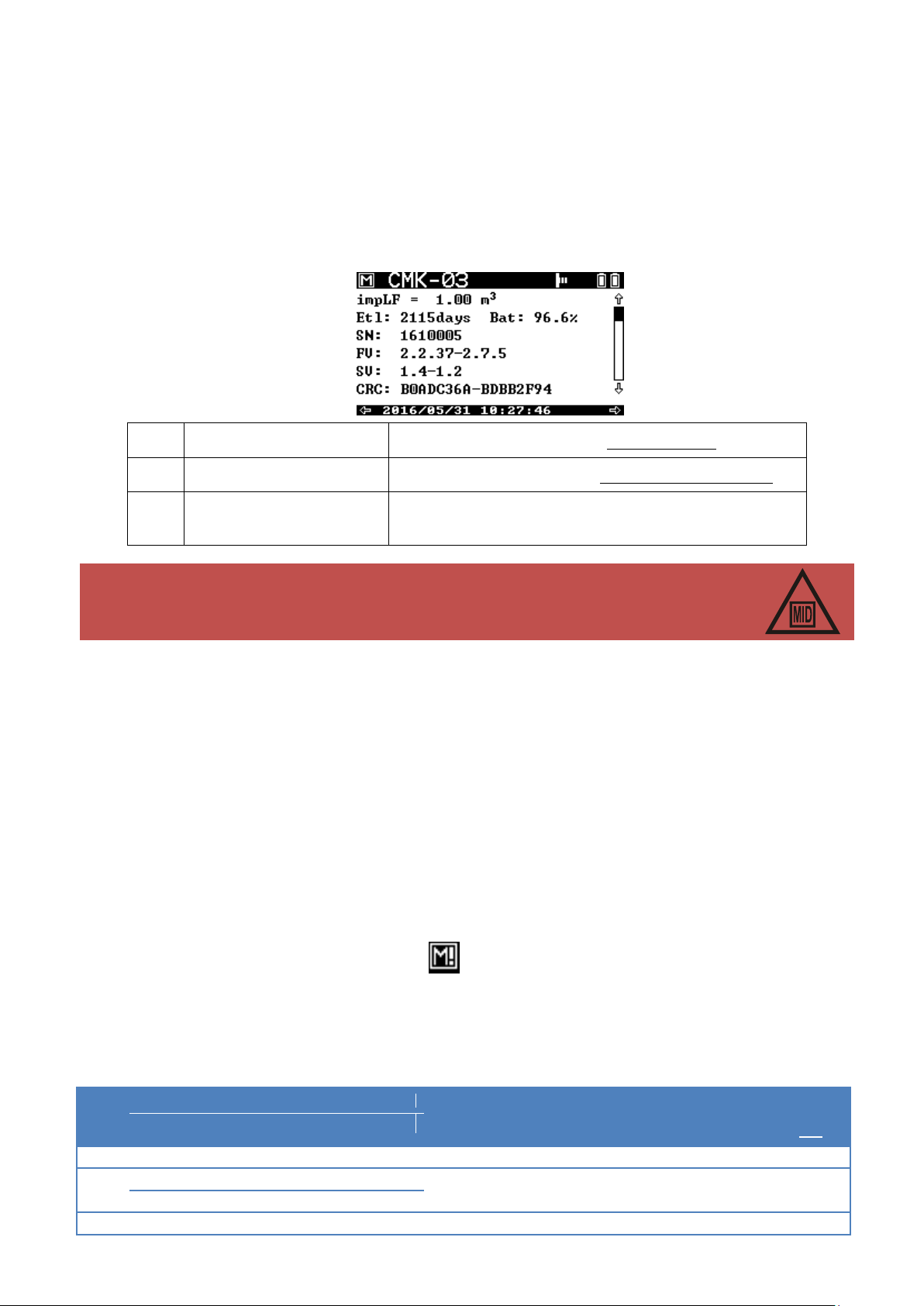
COMMON S.A. OPERATING INSTRUCTION CMK-03
FV:
2.35
-
2.7.3
Firmware Version – software for technological part
SV:
1.4
-
1.2
Software Version – software for metrological significant part
CRC:
B0ADC36A
-
BDBB2F94
CRC – the counted control sum from the parts of metrological
significant programs
The volume converter which is under control of the metrological law must have the
SV software version and CR control sum, which are conformed with the certificate of
type test data or future supplementation to the certificate.
ALARM
CODE
ALARM MESSAGE
ALARMS REASON - DESCRIPTION
COUNTING
TO
Vbe
REGISTERED PARAMETERS
PERMANENT ALARMS (CONTINUING IN TIME)
0
p1 out of range
overflow of the p1 pressure measuring range
YES
p1, Vb
1
t out of range
overflow of the t temperature measuring range
YES
8.6 Internal software identification
The CMK-03 internal software is divided on two parts.
The metrological part is significant for the measurement result and is checked and approved during a laboratory
tests of certification process. It is marked with the SV symbol, the number of version and the CRC control sum.
The technological part is not combined with the converter main functionality. This part has no affect on the meas-
urement result. It is out of the metrological control and can be develop and modify by the manufacturer according
to his Quality Management System. The technological part is marked with the FV symbol and the number of version. The information regarding the software version are presented on the one of MID displays.
The firmware update of the technological part may be performed by the manufacturer service or authorized manufacturer representative on the production and operation stage. The update does not require to remove the metrological seals and does not change the metrological properties of device. The firmware update requires authorization with the user password (the password is settable in the menu).
The update process is recorded every time in the internal “Events” register.
9 MID alarms
9.1 Principle of operation and list of alarms
The CMK-03 controls the correctness of values for all parameters incoming to the volume correction algorithm,
both measurement results and configurable algorithm parameters in a real time.
If there is an overflow of the converter measuring ranges, or an overflow of the applicability range or a change in
the metrological parameters which affect on the metrological result, then it occurs as follows:
alarm occurrence signal by flashing the icon on the top bar of the display main screens
the alarm registration with parameters in the MID Alarms register.
stopping of the volume counting to the Vb counter (in case of alarms and permanent overflows)
start of the estimated basic volume counting to the Vbe emergency counter.
Table 9.1 List of MID alarms – metrological significant
44
Page 45

COMMON S.A. OPERATING INSTRUCTION CMK-03
ALARM
CODE
ALARM MESSAGE
ALARMS REASON - DESCRIPTION
COUNTING
TO
Vbe
REGISTERED PARAMETERS
t, Vb 2 Alg. Z range exceeded
overflow of algorithm applicability range of the Z com-
pressibility coefficient designation.
YES
p1, t, Z, , Vb
3
p1 transduc. failed
damage or lack of the p1 pressure converter
YES
p1, Vb
4
t transduc. failed
damage or lack of t temperature sensor
YES
t, Vb 5 Subst. val. K1 alarm
overflow of algorithm range what causes with lack of the
algorithm solution (to calculation is is used the K1 substitute
value)
YES
p1, t, K1, Vb
6
p1 subst. val. on
authorized user has enabled the p1 alternative value (to
check measuring track procedure)
YES
p1, p1zast, User, Vb
7
t subst. val. on
authorized user has enabled the t alternative value (to
check the measuring track procedure)
YES
t, tzast, User, Vb
TEMPORARY ALARMS
128
Vb count. overfl.
Vb counter has reached maximum value and has started to
count from 0 value
NO
130
Conf. changed
authorized user has changed configuration of the metrological significant parameters
NO
USER, Vb
131
Usage > 70%
MID alarms register is filled in over 70 % (unsigned alarms
and/or on-going alarms)
NO
Vb
132
Database full
MID alarms base is full in 100%. The counting is continued
to the Vbe. There is impossible to change the configuration
of MID parameters. The acknowledge is necessary for further converter working process.
YES
Vb
133
Alarms acknowled.
authorized user has acknowledged the alarms
NO
User, Indeks ZMS, Vb
134
Battery < 10%
it remains less than 10% of the main battery estimated life
time
NO
Etl, Vb
135
New program
authorized user has updated the firmware
NO
FV, SV, CRC
The MID alarms register has a capacity for a minimum 256 records, which are stored in the nonvolatile
FLASH/FRAM memory. The MID alarms base is a rotary register what means that during saving operation the
oldest records are deleted and overwritten with the new entries.
The every record of MID Alarms Register is presented on the display and it contains:
ZM record unique index
alarm code and short alarm message (e.g. “(1) – p1 range overflow”)
data and time of the alarm recording (for temporary alarms)
data and time of the alarm beginning and end (for permanent alarms)
registered parameters – values of the presented figures which are stored in the moment of alarm occur-
rence
confirmation symbol – – if it is executed
The deleting of the oldest alarms is possible only when the following condition are respected:
the all alarms (records) are acknowledged in the oldest sector
the all permanent alarms are completed in the oldest sector
If the MID alarms data base is filled in 100% then occurs a limited work possibilities of the converter – in such
situation the volume is counted to the Vbe emergency counter and to the Ee energy counter. The possibility of the
configuration parameters changing is locked. Restore to fully functionality will occur after ending and acknowledgment of the permanent alarms.
45
Page 46

COMMON S.A. OPERATING INSTRUCTION CMK-03
9.2 Signaling, authorization and alarms acknowledgement
The every new alarm which is stored in the MID alarm register, causes the appearance of the flashing
icon on the top bar of main display screens. This means the occurrence of new, un-acknowledged alarms.
The alarm acknowledgment requires an authorization — the selection of the user account and the password.
The correct log-in operation causes the alarm acknowledgment from the oldest till latest. It will be also recorded
an information about the acknowledgement execution with the number of user account and ZMS index of the last
acknowledged alarm.
It is possible to acknowledge permanent, opened alarms (still on-going).
If icon is active (flash constantly without pulsing), it means that the all alarms are acknowledged, but the
alarm conditions still occur (at least one of the permanent alarms is still open).
The signaling MID alarms icon is disable, if the all alarms are acknowledged and all permanent alarms are ended.
The alarm conditions are stopped.
The login time maintenance is equal 3 minutes and is counted form the last user activity on the operating display
(except of the “Light” button). After this period of time a user will be automatically logged out.
The logout operation follows also:
after manually LCD display switching off what occurs after the multiple pushing ESC button
after LCD activity time running out — this parameter is configurable in the option: SettingsLCDAct.
time.
The login status is presented as a “Log:0” symbol on the bottom bar of the display, where 0 means number of the
logged user.
The login continuation status does not occur on the remote control working mode (Gaz-Modem 2/3 protocol
communication channels). In this case the authorization is required by every transmitted modification or acknowledgement.
Local Acknowledgement
The option is available in the LCD menu: Main Menu Archive MID Alarms Acknowled.
Remote Acknowledgement
The DP Table contains parameters:
“ZM index” – an unique index of the last registered MID alarm
“ZMS index” – an unique index of the last acknowledged MID alarm
The modification and recording of the “Index ZM” parameter on the value 0 (zero) occurs an acknowledgment of
the all alarms. The correct authorization is required.
9.3 Operating principles in the Vbe emergency conditions
If there is p1 pressure overflow greater than permissible measuring range but the converter is still working in the
possible measuring ranges (indicates the value), then volume estimation follows to the Vbe emergency counter
based on the p1 actual value.
If there is p1 pressure overflow greater than measuring possibilities of the converter, or converter is damaged and
does not response with the numerical value, then volume estimation follows to the Vbe emergency counter based
on the p1zast alternative value. The p1 value is presented on the MID screens with the substitute value and
graphical symbols which are described in the Part 11.1 LCD menu structure.
The edged value of the measuring range or the information NaN with the proper status is displayed on the screen
Value measurement (‘p1m’ parameter from DP Table) in the menu: Main Menu Measure Press.P1.
If there is t temperature overflow bigger than applicability range of the calculating algorithm, and indication is still
in the converter range, than volume estimation follows to the Vbe emergency counter based on the actual indication of the t temperature converter.
If there is a t temperature overflow greater than converter measuring possibilities, or it occurs a damage of sensor
or temperature converter, than volume estimation follows to emergency counter based on the tzast alternative
value. The results presentation is analogical as in case of the p1 pressure.
46
Page 47

COMMON S.A. OPERATING INSTRUCTION CMK-03
SYMBOL OF PARAMETER IN DP GazModem 3
SYMBOL ON LCD
NAME OF PARAMETER
impLF
LF weight
LF pulse value
Tb
Tb
base temperature
SymCfg
Simulation
activation of simulation for alternative values P1 and T
Tzast
Tzast
alternative value of gas temperature
P1zast
P1zast
alternative value of gas pressure
K1zast
K1zast
alternative value of K1 coefficient
algorytm
Algorythm
algorithm type for a calculation of compressibility coefficient
CFG2
Algorythm data
Type incoming data for an algorithm (parameters and, components)
CFG1
Gas comp.
type of the components concentration share in a gas mixture (by
mole and by volume)
CH4
CH4
methane
C2H6
C2H6
ethane
C3H8
C3H8
propane
n-C4H10
n-C4H10
n-butane
i-C4H10
i-C4H10
i-butane
n-C5H12
n-C5H12
n-pentane
i-C5H12
i-C5H12
i-pentane
If the calculating algorithm will find:
uncorrect gas composition / gas parameters out of the applicability range
p1 pressure out of the applicability range
t temperature out of the applicability range
an overflow of the indirect parameters calculated value,
but there is still an algorithm solution, than the volume estimation follows to the Vbe emergency counter based on
the K1 coefficient value, which is calculated by means of this algorithm.
If there is no algorithm solution (by a selected calculating algorithm), the volume estimation follows to the Vbe
emergency counter based on the K1zast alternative value.
In case of the K1=constant working mode, the volume estimation to the Vbe counter and emergency conditions
will occur if:
for K1=const=1 after p1 pressure overflow (p1 > 1,5 bar abs), or t temperature out of the converter
range -25°C 65°C,
for K1=const<>1 after p1 pressure overflow or t temperature out of the programmed limits “Limit p1 for
K1 = const <> 1” and Limit t for K1 = const <> 1” (the parameters of the bottom and top limits: dlp1K1,
glp1K1, dltK1, gltK1 are available in CCTool software; in Gaz-Modem 2/3 protocol and in DP Table).
All of the overflows, which cause an emergency conditions, are registered in the “MID Alarms“ and signalized by
the occurrence of flashing icon on the top bar of main MID screen.
10 MID integrations (configuration changes)
10.1 The operating principle and parameters list
The modification of the configuration parameters results with a record saving to “MIDregist.” interference register. The saved record contains the parameters combination and their changed values. In a Table 10.1 are shown
the parameters which affect on the measurement result and also the parameters which are saved to the interference register.
Table 10.1 Parameters recorded in the interference register
47
Page 48

COMMON S.A. OPERATING INSTRUCTION CMK-03
neo-C5H12
neo-C5H12
neo-pentane
C6H14
C6H14
n-heksane
C7H16
C7H16
n-heptane
C8H18
C8H18
n-oktane
C9H20
C9H20
n-nonane
C10H22
C10H22
n-dekane
C2H4
C2H4
ethylene
C3H6
C3H6
propene
i-C4H8
i-C4H8
i-butene
cisC4H8
cisC4H8
cis-2-butene
C4H8
C4H8
isobutene
1-2C4H6
1-2C4H6
1,2-butadiene
1-3C4H6
1-3C4H6
1,3-butadiene
1-C5H10
1-C5H10
1-pentene
C5H10
C5H10
cyclopentane
C6H6
C6H6
benzene
C7H8
C7H8
toulene
CH3OH
CH3OH
methanol
H2
H2
hydrogen
H2O
H2O
steam
H2S
H2S
hydrogen sulfide
CO
CO
carbon monoxide
He
He
helium
Ne
Ne
neon
Ar
Ar
argon
N2
N2
nitrogen
O2
O2
oxygen
CO2
CO2
carbon dioxide
SO2
SO2
sulphur dioxide
AIR
Air
air
Hs cfg
Hs
heat of combustion
d cfg
D
relative density (configurable)
CO2 cfg
mCO2
molar proportion of carbon dioxide (configurable)
H2 cfg
mH2
molar proportion of hydrogen (configurable)
10.2 Signaling, authorization and alarm acknowledgment
If it will be change any parameters of data, which have affect on a measurement result and this change will be
authorized via user password, the converter will record a temporary alarm in MID alarms register with code: “130”
and message “configuration change”.
This operation will cause the occurrence of flashing icon on the top bar of display main screens. There is
require to acknowledge this alarm by an authorized user.
11. Local service
11.1 LCD menu structure and main MID screens
The CMK-03 is equipped in the LCD graphical screen with a backlight and an adjustable contrast. The display is
operated by using the 7 buttons keyboard which allows for an information scrolling or parameters configuration.
The main buttons functions are listed below:
ESC – exit to upper level, cancel of changes
< – scrolling / switching left
˄ – scrolling / switching up
˅ – scrolling / switching down
48
Page 49
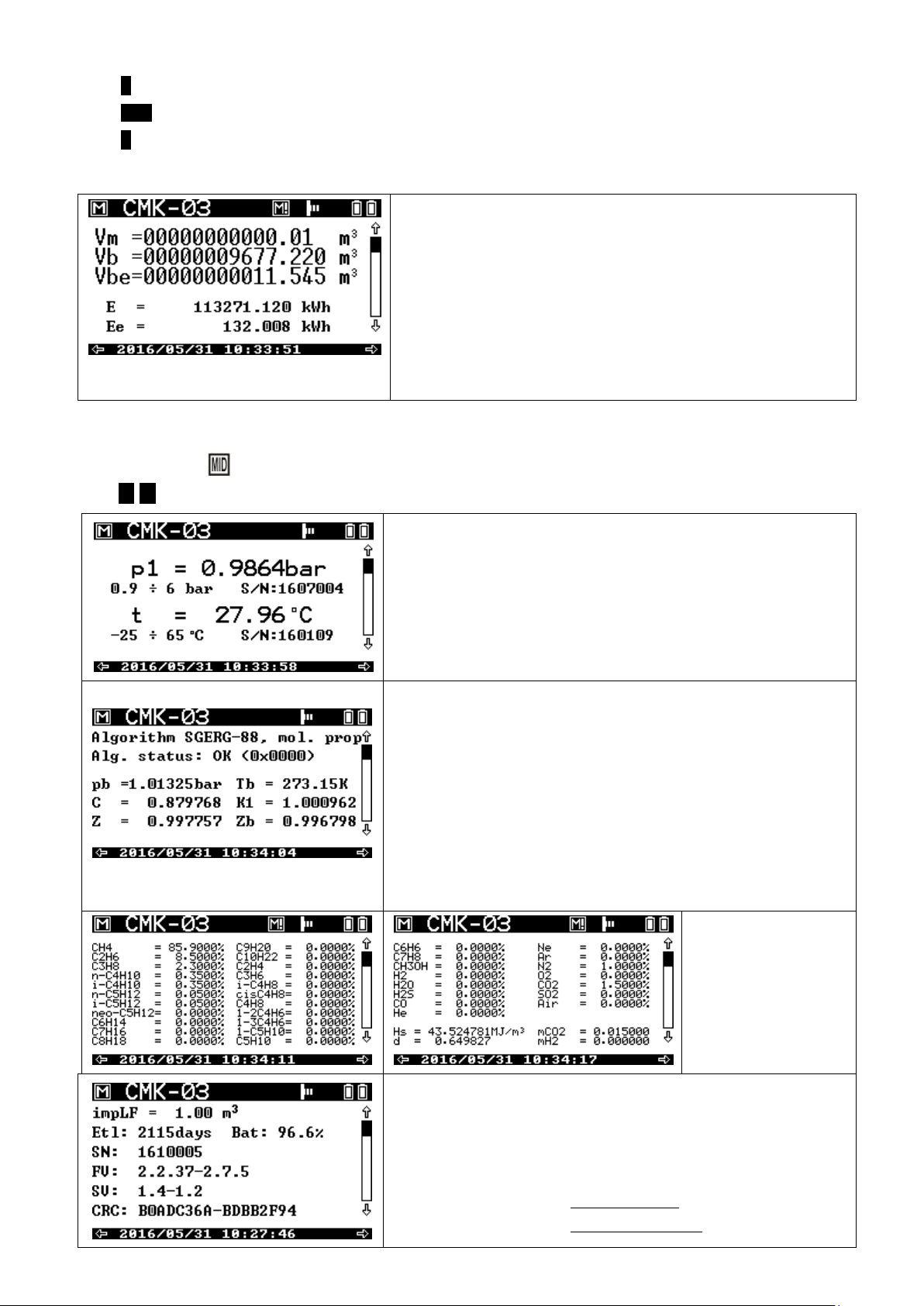
COMMON S.A. OPERATING INSTRUCTION CMK-03
Vm – volume counter in the measuring conditions.
Counter must be set on the value accordant to the gas meter counter
(description below)
Vb – gas volume counter in the basic conditions (value after calculation)
Vbe – gas volume counter in the basic conditions when occurrence the
emergency conditions
E – energy combustion counter
Ee – combustion emergency counter in emergency conditions
p1 – gas pressure (absolute). Below are listed: operating ranges and
converter serial number.
t – gas temperature. Below are listed: operating ranges and converter
serial number.
Algorithm – actually set calculating algorithm of the compressibility coef-
ficient and a type of the gas composition (molar / volume or from parameters)
Alg. status – calculating method status (description in farther part of the
operating instruction)
pb; Tb – basic conditions 1.01325bar ; 273.15K
C – coefficient of the conversion to the basic conditions
Z – compressibility coefficient in the measuring conditions
Zb – compressibility coefficient in the basic conditions
K1 – relative compressibility coefficient Z / Zb
the percentage gas composition, and displayed
the all gas components
and the gas coefficients
impLF – set LF pulse value
Etl – estimated converter operating time on the battery set, when occurs
a constant working conditions
Bat – percentage batteries status
SN – converter serial number
FV – firmware version of the technological part
SV – software version of the MID metrological part
> – scrolling / switching right
ENT – enter to lower level, acceptation of changes
ϙ – screen backlight
The main screen displays the basic accounting values as follows:
The main indication of the measurement such as: volume counter in the basic conditions, and others indications
and significant parameters from metrological point of view, are displayed on the several main screens which are
marked with icon (named as MID screens). The scrolling between the further MID screens is possible by
using < > :
49
Page 50
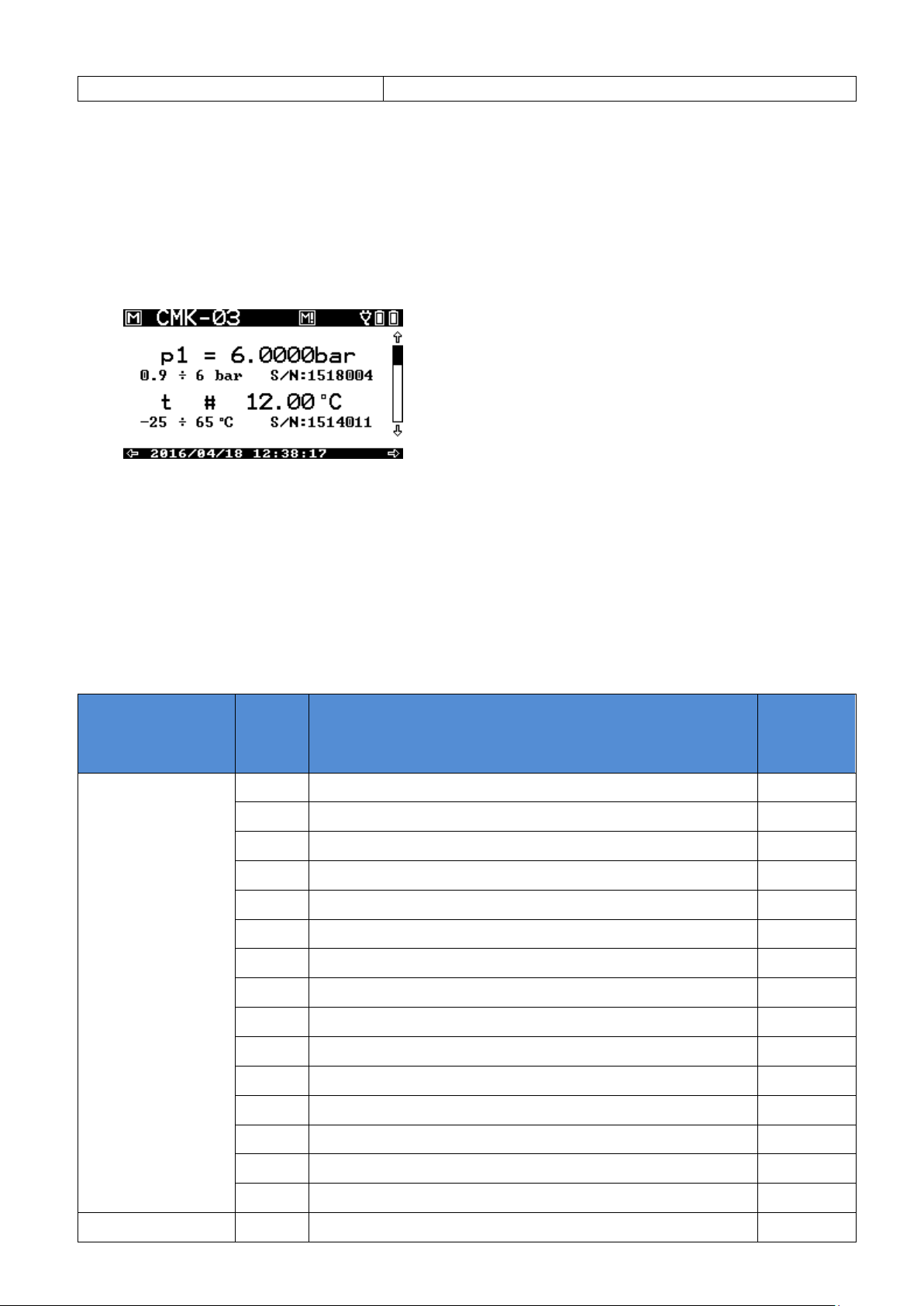
COMMON S.A. OPERATING INSTRUCTION CMK-03
CRC – control sum of the MID software part
ALGORITHM
CODE
DESCRIPTION
INTERRUPT
K1 CALCULATION
K1 == K1zast
SGERG – 88
0x0000
correct calculations
NO
0x0001
error of gas composition
YES
0x0002
lack of solution
YES
0x0004
gas pressure out of range for selected method
NO
0x0008
gas temperature out of range for selected method
NO
0x0010
heat of combustion out of range for selected method
YES
0x0020
relative density out of range for selected method
YES
0x0040
molar proportion of CO2 out of range for selected method
YES
0x0080
molar proportion of H2 out of range for selected method
YES
0x0200
lack of solution – WirB
YES
0x0400
lack of solution – WirC
YES
0x1000
input data conflict
NO
0x2000
calculated molar proportion of N2 out of range
NO
0x4000
N2 + CO2 out of range
NO
0x8000
conflict of result for N2
NO
0x0000
correct calculations
NO
The presentation of the measuring range overflow and an usage of the alternative value instead of p1 and t is
shown on the screen by using symbols “!” and “#” as follows:
sign “=” correct measurement value
flashing sign “= / !” value from the converter is out of measuring range, processing alarm
flashing sign “# / !” lack of the value, system alarm, used alternative value
sign “#” simulation activated, used alternative value
The example screen with presented overflows:
The symbols which used for the calculated K1 coefficient:
sign “=” correct value
flashing sign “= / !” value out of measuring range, process alarm
flashing sign “# / !” lack of value, system alarm, used alternative value
The information about the Status.alg. status of operating algorithm is presented on the third MID screen. There
are two possible states “OK” or “ERROR” with a proper error code. The error codes of the algorithm are shown in
Table 11.1.
Table 11.1 Calculating algorithm – error codes
50
Page 51
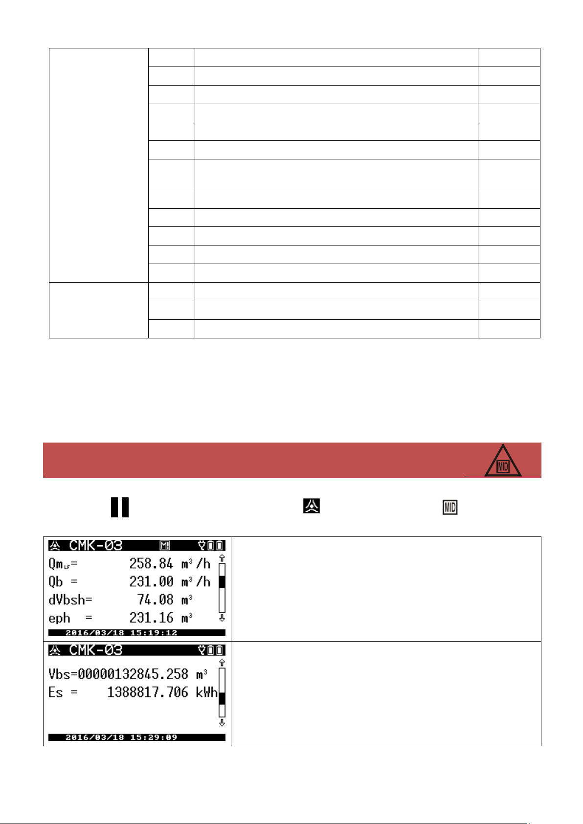
COMMON S.A. OPERATING INSTRUCTION CMK-03
0x0001
error of gas composition
YES
0x0002
lack of solution
YES
0x0004
gas pressure out of range for selected method
NO
0x0008
gas temperature out of range for selected method
NO
0x0010
heat of combustion out of range for selected method
NO
0x0020
relative density out of range for selected method
NO
0x0040
molar proportion of CO2 (carbon dioxide) out of range for selected
method
NO
0x0080
molar proportion of H2 (hydrogen) out of range for selected method
NO
0x0100
molar proportion of N2 (nitrogen) out of range for selected method
NO
0x0200
molar proportion CH4 (methane) of out of range
NO
0x0400
molar proportion of C2H6 (ethane) out of range
NO
0x0800
molar proportion of C3H8 (propane) out of range
NO
K1=const.
0x0000
correct calculations
–
0x0004
gas pressure out of range for selected method
–
0x0008
gas temperature out of range for selected method
–
The occurrence of the status alg. value different from the value 0x0000 causes an alarm
conditions and starts the volume counting to the Vbe counter.
Qm
LF
– current gas stream in the measuring conditions. The LF index means
that the value determination is based on the low frequency transmitter
pulses. If it will be determinate on basis of the high frequency transmitter, it
will be displayed HF index.
Qb – current gas stream in the basic conditions
dVbsh – increase Vbs counter in the current hour
eph – estimated dVbsh hourly volume increase in the current hour
Vbs – summary Vb and Vbe volume counter
Es – summary E and Ee counter of the combustion energy
The defined error codes are presented in hexadecimal notation. The status alg. value may be a bit sum of the
error codes. The occurrence of a several errors at the same time is presented as a sum of the proper error codes.
For example: the errors such as:
error of a gas composition (0x0001)
error “H2 molar proportion (hydrogen) is out of range” (0x0080)
The status value (concerning these two errors) will be presented as (0x0081).
The screens with a technological parameters, which are not cover by the metrological control may be selected by
using buttons ˄ ˅. After this the logo of COMMON S.A. will appear instead of the icon in the top left
corner of screen.
51
Page 52
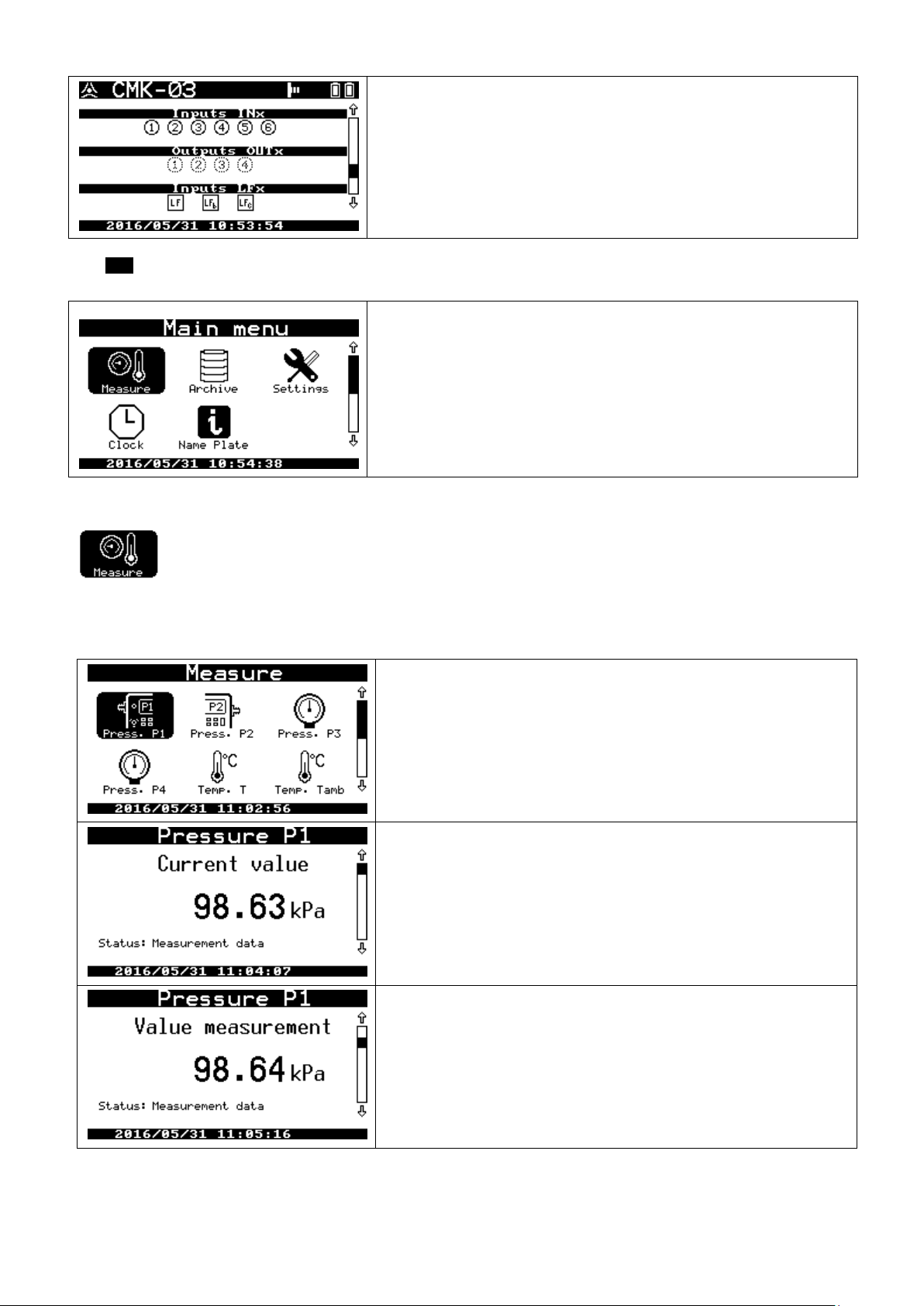
COMMON S.A. OPERATING INSTRUCTION CMK-03
inputs INx – current status of the inputs 1 – 6 (contact / NAMUR)
outputs OUTx – current status of the double-stage outputs 1, 2, 3/LF, 4/HF
inputs LFx – current status of the pulse inputs of converter
Measure – current measuring values are displayed on the several screens
Archive – scrolling of the registered data base
Settings – the configuration view and changing the operating parameters
Clock – actually time and clock settings
Name plate – converter name plate
Press.P1 and Press.P2 – concern the internal pressure converters
Press.P3 and Press.P4 – concern the additional, external pressure con-
verters ( CPC-03) which are connected to ExtCPC clamps
Temp.T – gas temperature converter
Temp.Tamb – housing (environment) temperature converter
current p1 pressure value, used to the calculations
current converter p1m pressure measured value
The ENT button is to be select to enter the main menu, from any level of the above described screens. The main menu allows
for an access to farther parameters and converter functions.
11.1.1 Menu measure
Menu contains detailed information about:
measured values which has received from the internal and external measuring converters
converters parameters
converters settings
52
Page 53
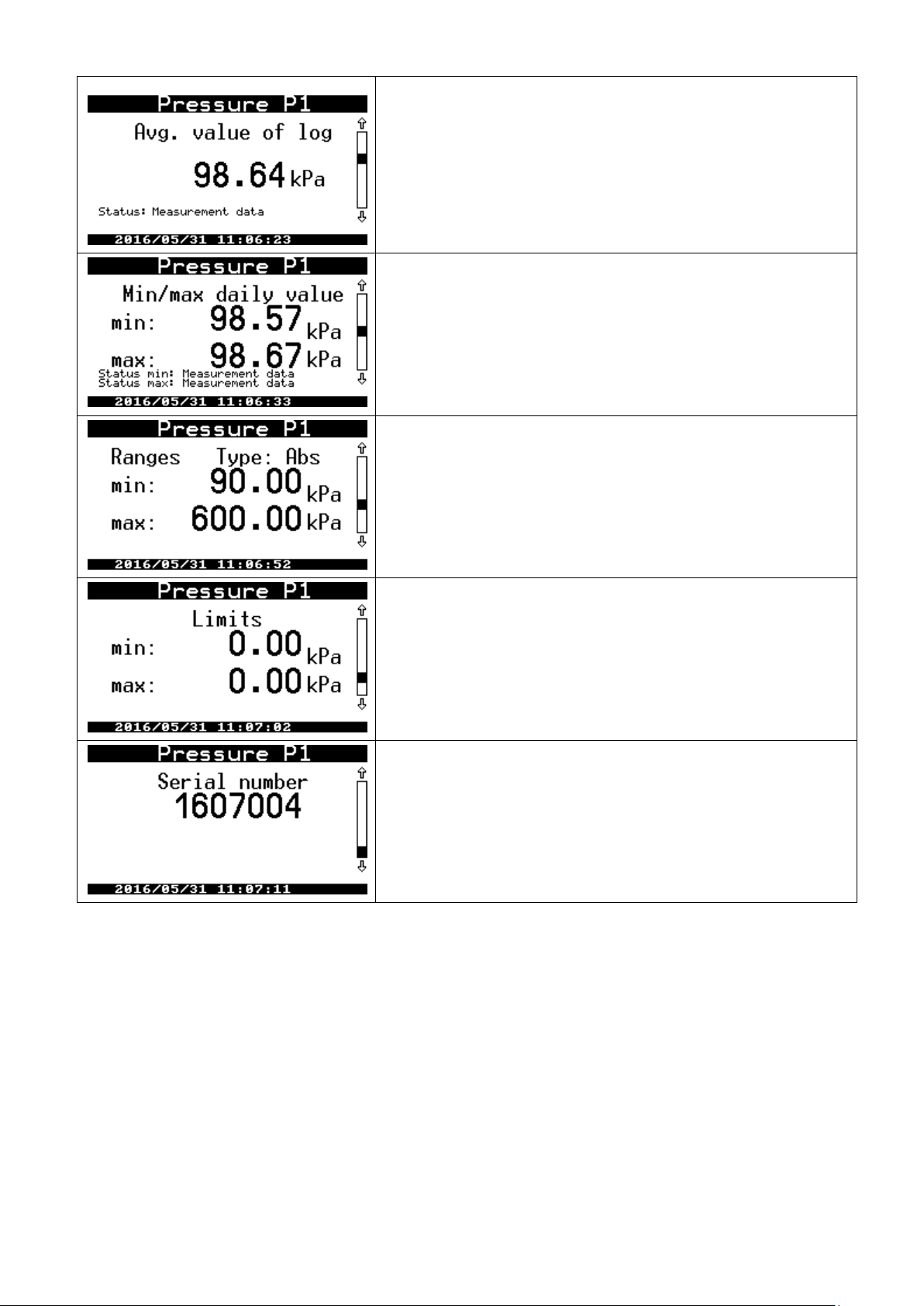
COMMON S.A. OPERATING INSTRUCTION CMK-03
average value in the registration period
minimum and maximum measured value in the current gas day
converter measuring ranges
set alarm limits
converter serial number
The menu of the others measurements looks analogical. If there is no converter e.g. P2 or P3 or P4 is inactive, it
will be displayed a message “Measurement inactive” after entering in their menu.
The every measurement has parameters Status. The values and status meanings of the measuring parameters
are listed below:
“Measurement data” correct result of the measurement
“Range overflow – process alarm” over crossed converter measuring ranges; but there is numer-
ical measurement result; type: processing alarm
“Range overflow – system alarm” over crossed converter measuring ranges, or the converter is
damaged, there is no measuring result; type: system alarm
“Constant of algorithm” if there is activation of the substitute value
There is displayed also a field “Info” (below of the field “Status”).
The “Info” can receive a values and meanings as follows:
“Communication error with the converter ” in case of the temporary communication error
53
Page 54
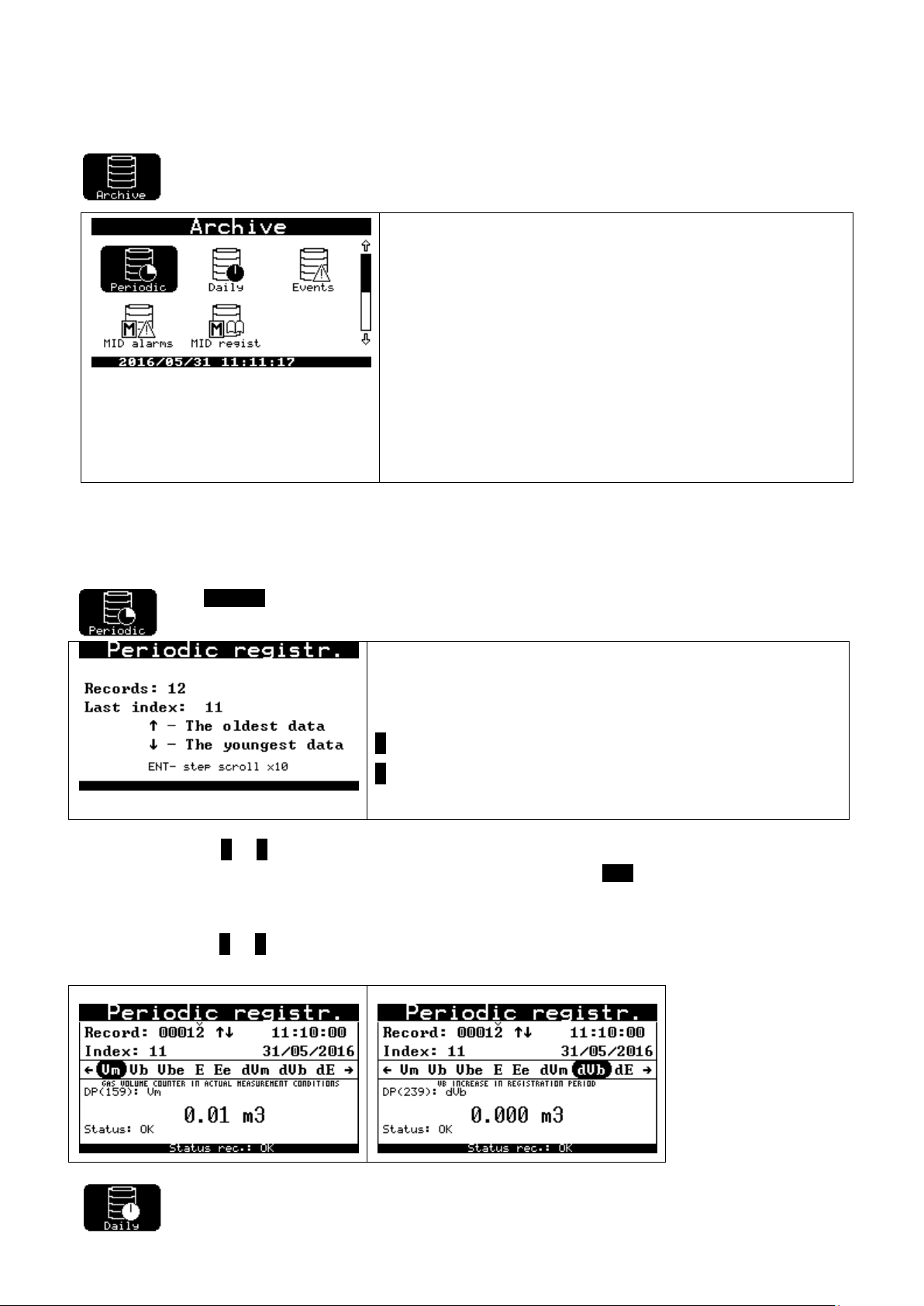
COMMON S.A. OPERATING INSTRUCTION CMK-03
Periodical – data registered according to the set period of time
(default 10 minutes)
Daily – data registered at the end of every gas day
(default set at 6:00 a.m.)
Events – events list and alarms which have been registered by the con-
verter
MID alarms – events list and alarms which have affect on the accounting-
measuring parameters (MID)
MID regist –register of interferences and a recording of changes in the
configuration of the parameters
Records – records quantity stored in the counter memory
Last index – unique index of the last record. If the converter memory is full
the number of records will stop to increase (it will be oscillate near maximum value) and the last index will be increment further.
˄ – the oldest data
˅ – the youngest data
“Limit overflow” overflow of the set measuring limits
11.1.2 Menu Archive
Menu contains the all values registered in the converter memory.
The operating rule and alarms acknowledgment are described in the part: MID alarms and MID interferences
(configuration changes).
The Periodic menu:
The selection of the ˄ or ˅ button causes the data base display appropriate from the oldest or from the newest
saved data. Data may be scrolled one by one (default set). The pushing ENT button during the scrolling, will
switch step of scrolling between 1, 10, 100 e.t.c. It is marked with “v” sign above the record digit. This informs
which digit is actually scrolled from the number of records.
The selection of the < or > causes the switching between parameters registered in record. There is a line below
where are presented the DP Table description and DP Table parameter number of the Gaz-Modem 2/3 protocol.
The browsing of the “Daily” menu is based on the same rule as a browsing of the “Periodical”
54
Page 55
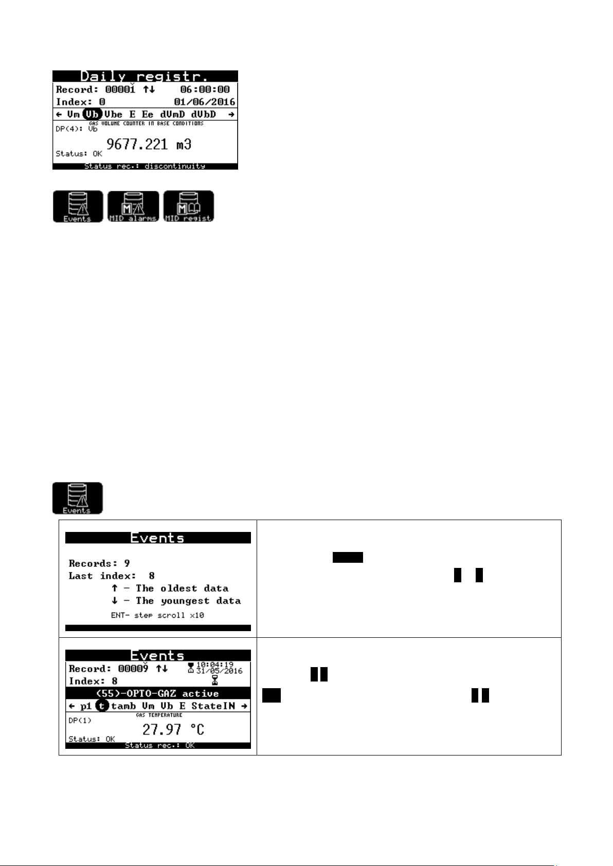
COMMON S.A. OPERATING INSTRUCTION CMK-03
after selection of Events menu, the first displayed information is an
amount of events in the counter, the selection ˅ or ˄ causes a display
of the youngest or the oldest saved event.
the buttons ˅ ˄ are used to switching between another events, the
ENT button changes step of switching, the buttons < > display another
parameters which are saved in the record.
menu.
Events, MID alarms, MID register
According to the requirement of the MID directive the CMK-03 has two additional data base registers: MID alarms
and MID regist. (register of MID interferences). The functionality of these registers have been checked and
metrological approved.
The MID alarms subject under control and must be read and acknowledged (confirmed). If there is no place for
new MID alarms, the old alarms can be removed after acknowledgment from the converter memory.
If the base will fulfill with the unacknowledged alarms, the converter will lock a possibility of further base volume
counting to the Vb counter. It will start to count to the Vbe counter, what will last until alarms reading and their
acknowledgement.
The acknowledgment of the MID alarms can be done both manually and via telemetric connection by means of
respectively function of the Gaz-Modem 3 protocol. The manual acknowledgment can be done from the menu
level: Archive MID alarms. Details are described in part 9.2 and in text below.
The MID register is a type of configuration changes register for accounting parameters. The acknowledgment is
not required.
The Events register contains an all information from the MID alarms and the MID register. There is also information about additional alarms, technological events, functional events, which are available locally and remotely
via Gaz-Modem 2/3 protocol.
The browsing of the Events and alarms data menu.
55
Page 56
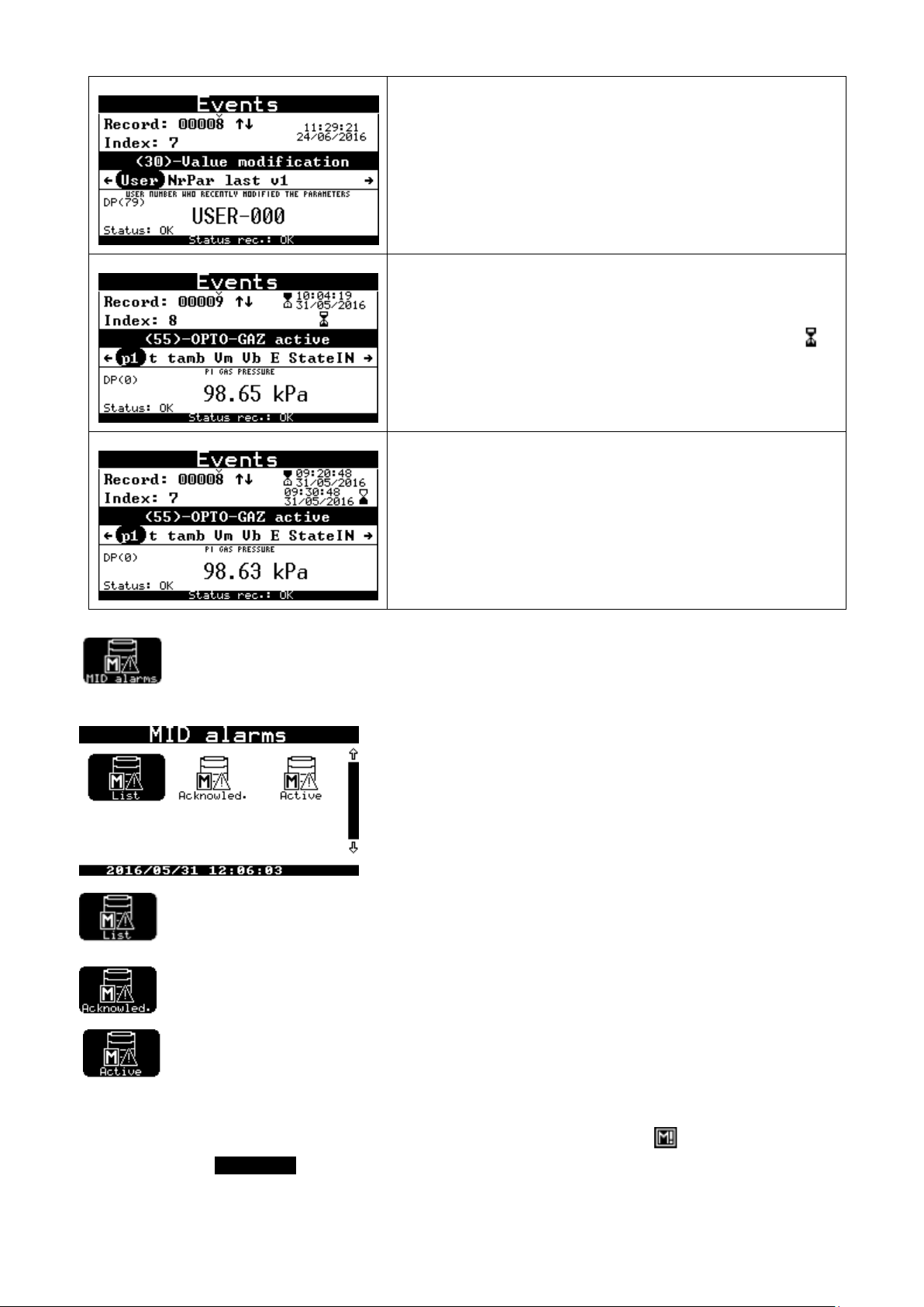
COMMON S.A. OPERATING INSTRUCTION CMK-03
There is an saved information about the user who has made the
changes.
There is an example of event which is no MID type: the status change
of the signaling input. The event is “on going” what is marked with
icon in position of the event ending time.
There is an example of event which is already ended. It occurs information about time of event ending, index has not been changed.
The browsing of the MID alarms data base
menu dedicated to the alarms base browsing — it works similar to the events browsing
menu dedicated to the alarms acknowledgment
menu dedicated to the active alarms browsing
If there is at least one unconfirmed alarm in the converter, it is signaled by flashing icon on the top bar of the
screen. If the menu Acknowled will be selected, it will display:
56
Page 57
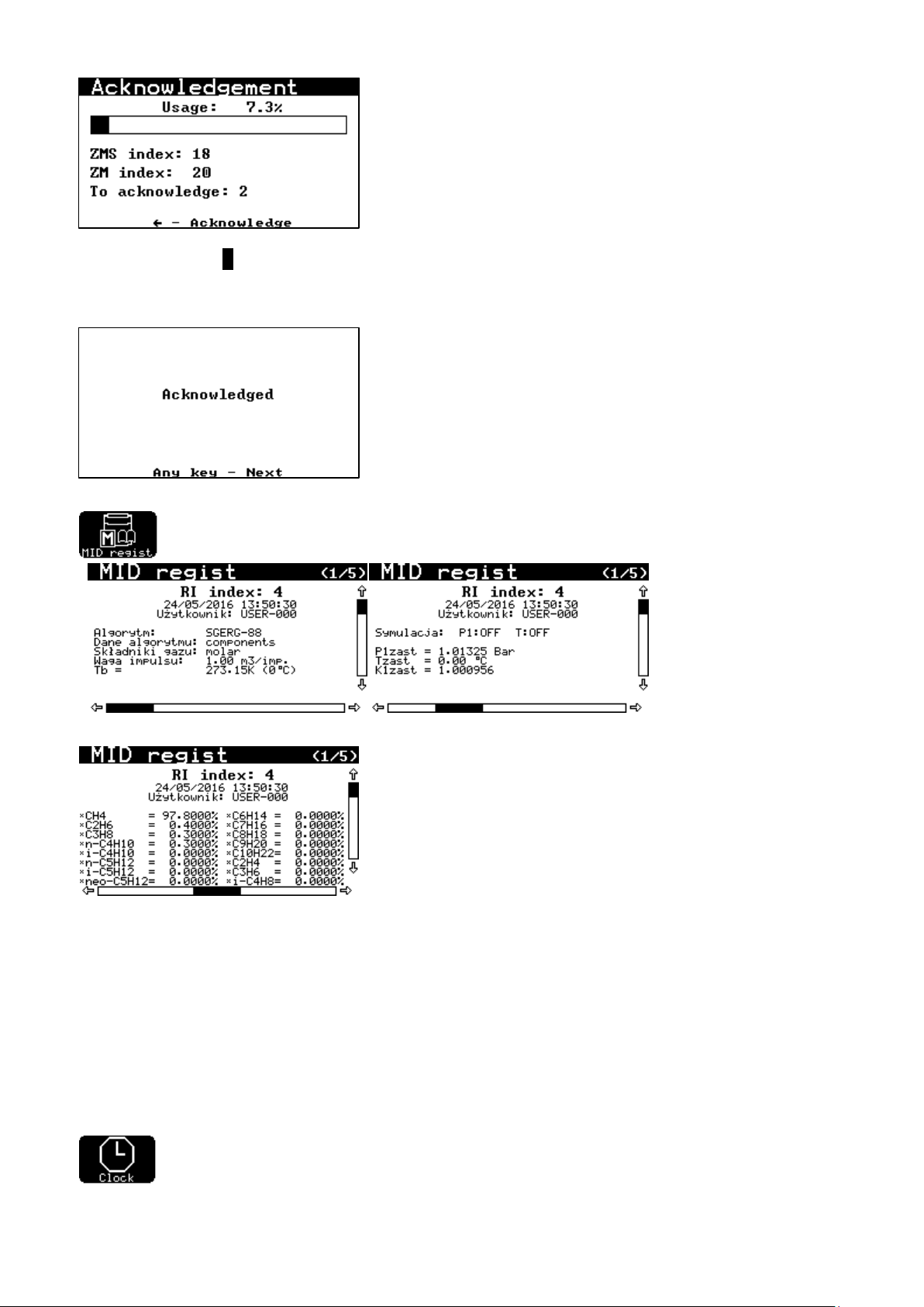
COMMON S.A. OPERATING INSTRUCTION CMK-03
The selection of the < button causes a MID alarm confirmation. The acknowledgment can be done only by authorized user. The description of the log in procedure is contained in part 11.2.2. After the successfully acknowledgment it will be displayed screen with a confirmation message as below:
There is the interference register of the accounting parameters. The register contains information
about the user, who has made modification and about recorded parameters after changing.
11.1.3 Menu Clock
Menu clock contains two screens which display: actually time, data with day of the week and dates
of the time changes (summer / winter).
57
Page 58
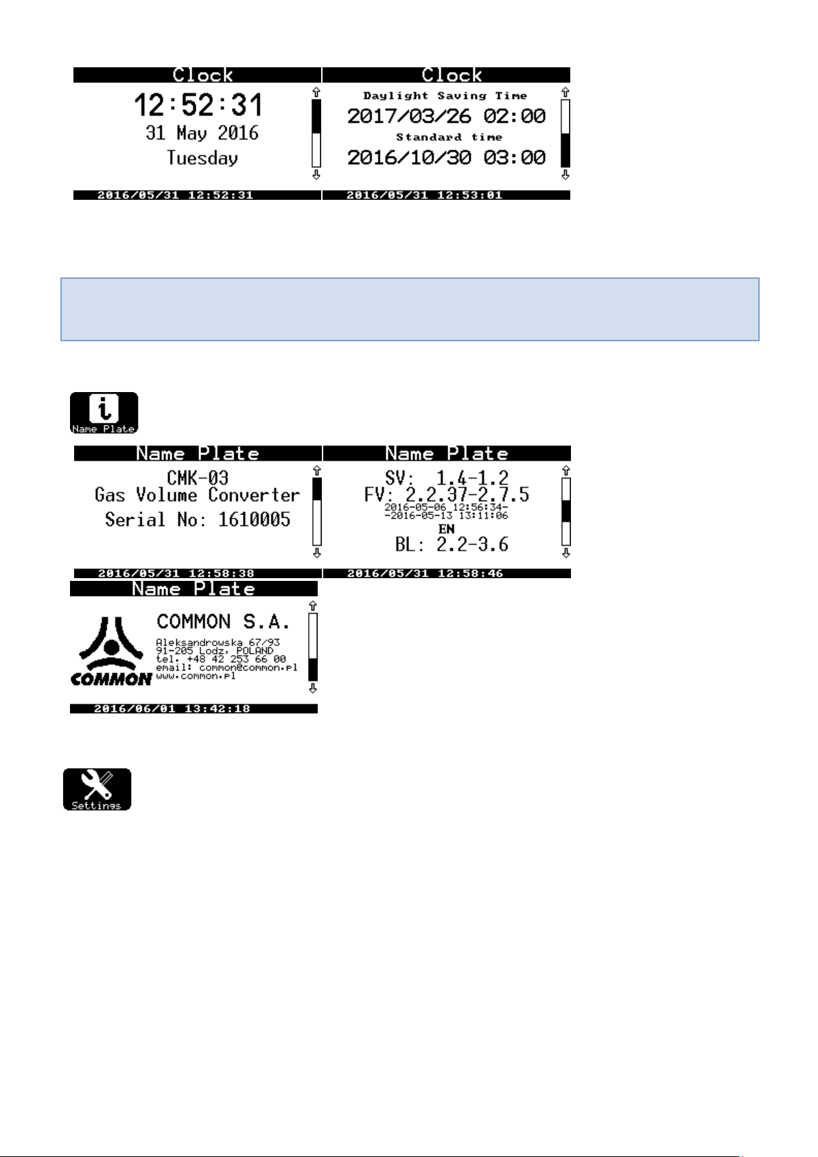
COMMON S.A. OPERATING INSTRUCTION CMK-03
The RTC clock and internal calendar is very precise. Typical error does not exceed 5 ppm, what means
that is smaller than 0,5 s / 24h. It assures stable operation and there is not necessary to synchronize
time in the device. The data, which are registered in many devices are correlated between each other.
If the option of the time “auto change” (summer / winter) is disabled, it will be not displayed the date which informs
about time changing. It will be displayed a message “Auto.change: NO”
11.1.4 Menu Name plate
Menu name plate contains 3 screens with information about: serial number, firmware version and
manufacturer information.
11.2 Menu Settings
11.2.1 Configuration after installation
The device requires a configuration of basic operating parameters such as:
Vm counter status, according to the indication of the gas meter index head
to record the Vb counter status in the protocol (not modifiable)
LF pulses weight
the gas meter constant, if it will be used HF input for stream determination
gas composition (to configure based on the parameters or on fully gas composition. It depends
from selected calculating method)
the calculation algorithm of the compressibility coefficient (SGERG-88, AGA8-92DC, K1=const)
to control date / time and automatic time changing mode
the registration period and start of the gas day
users: their passwords and permissions
58
Page 59
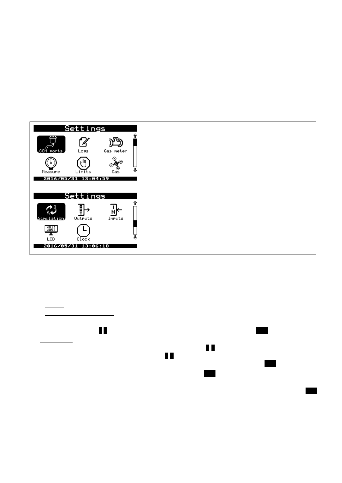
COMMON S.A. OPERATING INSTRUCTION CMK-03
COM ports – transmission parameters
Logs – registration period and start of the gas day
Gas meter – gas meter parameters
Measure –measuring converters configuration
Limits – limits of the measuring figures
Gas – the gas composition and gas parameters
Simulation – alternative values of the measuring figures
Outputs – double-states outputs
Inputs – double-states inputs
LCD – activity time, display contrast, units of the displayed figures
Clock – current data / time, time change summer / winter
to control and acknowledge current MID alarms
transmission parameters on theCOM1/OPTO-GAZ, COM2 or COM3 ports
Additionally can be configured:
the name of a gas point or a gas station
the ranges and limits of the Qm / Qb streams and other measuring parameters
the LCD format of displayed data — it depends on the ranges of applied converters
The converter manual configuration can be done in menu: “Settings”. There are all functions collected on two
screens which are dedicated to set the operating parameters.
The parameters entering method is common for all of the entered figures. The method has been described in this
instruction on the basis of configuration for serial ports parameters.
11.2.2 Parameters setting – general information
The entered parameters may be shared on two basic types:
type list — where is possible to select one of the available options
the parameter type number, where can be set a numerical value.
The type list parameter can be only a selection from the list of the available options such as ON/OFF, YES/NO, or
baud rate. It is set by using ˄ ˅ buttons, which scroll the list and should be confirmed with ENT button.
The type number parameter is an integer or a real number with defined the range (e.g. the Gaz-Modem address
or Vm counter). In this case an every digit is set (scrolled) by using ˄ ˅ buttons, sometimes with decimal point.
The another digit is selected to the edition by using < > buttons. This buttons move a cursor on the position of
next digit. The entire number is set by means of this method, and it should be confirmed with ENT button.
The entered modification can be canceled in every moment by using ESC button.
The converter parameters are grouped according to the menu structure. If there is a changing only in one of the
parameters, this parameter is marked with a small star sign on the left side of its name. The selection of ESC
button, displays an enquiry regarding to the confirmation for entered changes.
59
Page 60
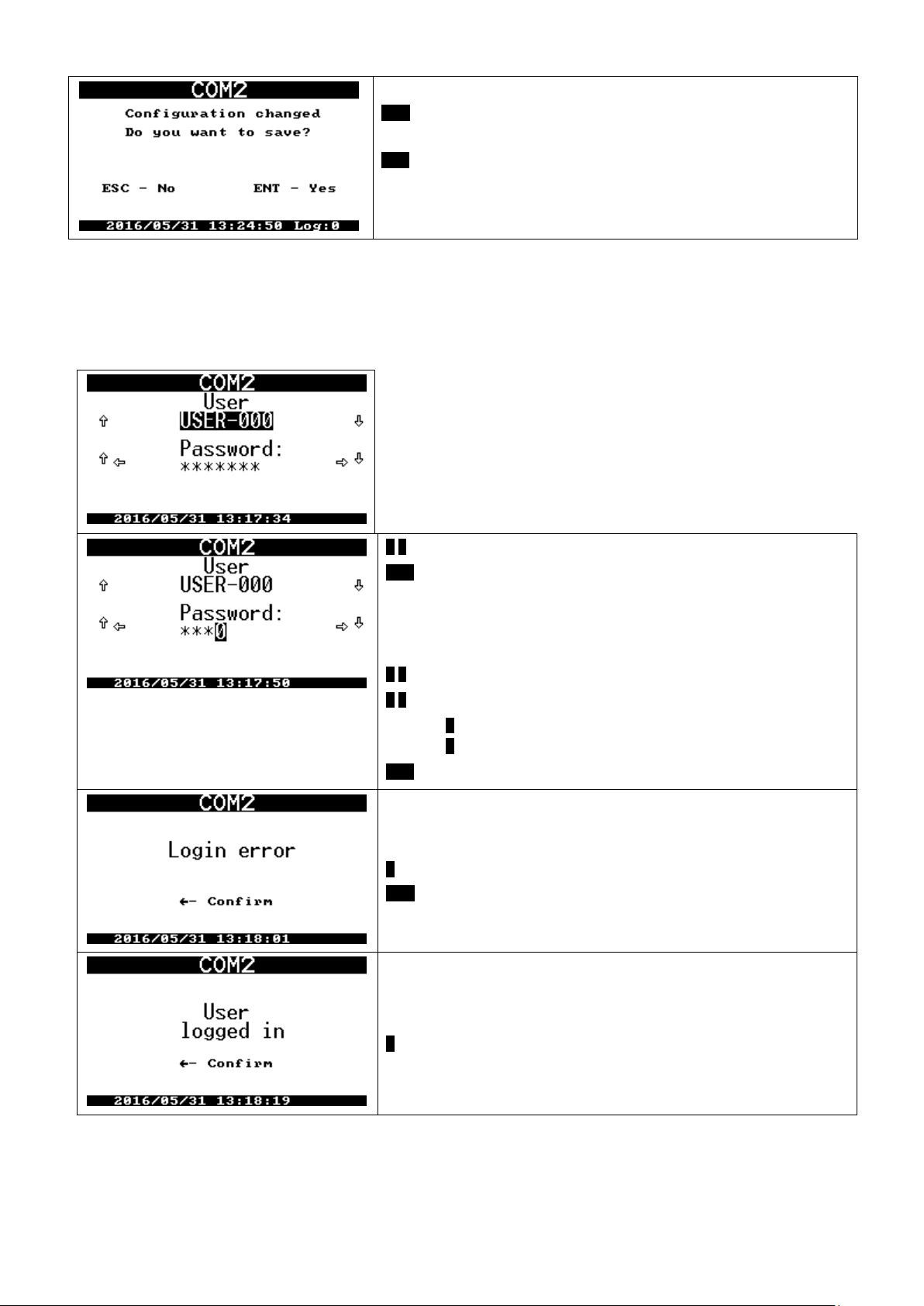
COMMON S.A. OPERATING INSTRUCTION CMK-03
ESC button cancels every entered changes
ENT button confirms entered changes
˄ ˅ buttons allow for user selection
ENT button confirms the user selection.
The entering of user password:
“USER-000” has the default password “0000”.
The password is not a number. It need to be enter the four zeros.
˄ ˅ buttons set the value of the selected chart
< > button navigate between password charts.
> button moves indicator to the next chart
< button occurs to go back and cancel current position
ENT button confirms the entered password
This message informs about wrong password
< button causes step back to log in window.
ESC button allows to enter the password again or cancel the operation
This message informs about proper user log in procedure.
< button causes the return to parameters setting.
11.2.3 Log-in
The modification of the selected parameter requires to log in and user authorization. This is not necessary
if the all parameters concerning the COM1 and OPTO-GAZ ports. There is no separated login function. The login
screen is displayed, when there is no logged user:
60
Page 61
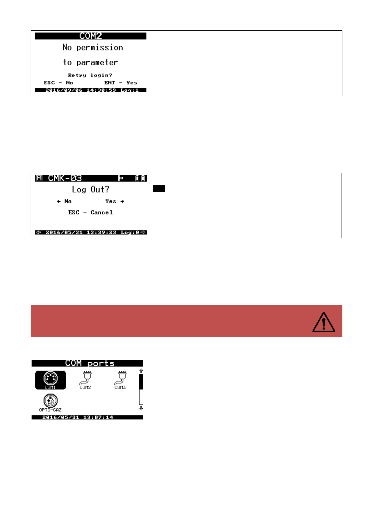
COMMON S.A. OPERATING INSTRUCTION CMK-03
This message informs about no required permissions for a logged user to
modify the parameter from the selected parameter group
ESC button allows for log out operation. It will be displayed a question
regarding the log out operation, what secures a user before unplanned log
out.
If there was no logged user, the screen will disable immediately.
The default password of USER-000 is set as four zeros: 0000.
It is recommended to change the default password to avoid unauthorized access to con-
verter configuration!
There are a few permission types which allow to modify a parameters group. The users settings and their permission level are described in the part 0.
The user log on time is maintained during 4 minutes when it has been made by using keyboard. This time period
is counted since the last pushing of any keyboard keys (except the backlight button). After 4 minutes it will occur
automatically log out.
The screen is active and the backlight is maintained during the login time period.
The log out operation is required to log in for another user.
While a user is logged, there is displayed message: Log:x, where x indicate a user number: 0..3. The CMK-03
may have defined 4 users (USER-000 — USER-003). It may be assigned a different permissions levels and individual passwords for every of users. The password may contain a number from 4 till 7 digits.
11.2.4 Parameters setting of the COM ports
The menu COM ports allows to set as follows:
the physical COM ports parameters
MODBUS addresses
GazModem3 protocols addresses.
The CMK-03 is hardware equipped in three serial ports. The COM1 and OPTO-GAZ ports share one physical
serial COM1 port, but have possibility for an independent configuration of the transmission parameters. The
placement of the OPTO-GAZ head will deactivate the COM1 port.
61
Page 62
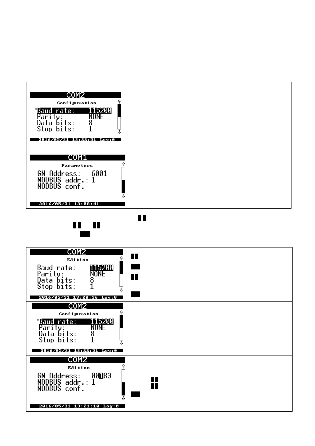
COMMON S.A. OPERATING INSTRUCTION CMK-03
The physical parameters with the settings recommended for the telemetric:
Baud rate can be selected from list: 300, 600, 1200, 2400, 4800, 9600,
19200, 38400, 57600, 115200 bits/s.
Parity: NONE, EVEN, ODD
Data bits: 8, 7
Stop bits: 1, 2
GM address: the GazModem protocol address is a number from the range
1..65534 (default setting depends from the serial number and the port
number)
MODBUS addr.: the MODBUS RTU protocol address is a natural number
from the range 0..247(default 1).
MODBUS conf.: option with submenu to configure the sequence of the
sent bytes.
˄ ˅ buttons switch a parameter
ENT button causes a parameter selection and an edition
˄ ˅ buttons allow for selection of the required value (when the parameter is
being edited)
ENT button confirms the entered value
EN button confirms the set value and returns to the parameters list.
˄ ˅ buttons select another parameter to modification
* symbol is located on the left side of the modified parameter value has
been changed but is still unsaved
GM address and MODBUS address:
˄ ˅ buttons set the individual digits value
< > buttons switch between digits.
ENT button confirms the entire set address
The COM1 port is located on the converters housing (TUCHEL socket) and COM2 and COM3 ports are located
on the internal terminal strips.
The COM1 and OPTO-GAZ ports parameters may be modified without authorization but the parameters of the
COM2 and COM3 ports after logging. The parameters setting looks the same for every port. If there is selected
the menu: Settings COM ports COM1 it can be seen the COM1 port setting, which are displayed on two
screens.
Please notice that the default setting are marked with bolded letters in the further, below description.
The baud rate is selected from the list by using ˄ ˅ buttons. The digits of the GM address are set and selected to
the edition by using ˄ ˅ and < > buttons.
It need to be selected ENT button to change the parameter. After this the parameter value will be displayed in a
negative-view as selected to the edition.
62
Page 63
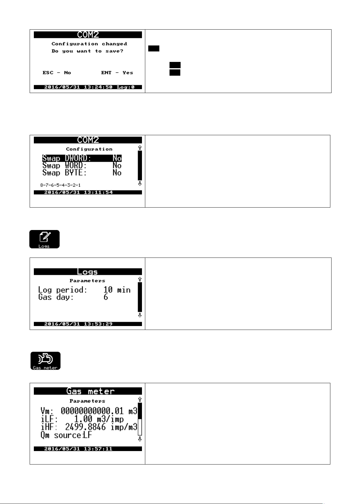
COMMON S.A. OPERATING INSTRUCTION CMK-03
ESC button ends the parameter configuration and occurs the screen dis-
playing with question regarding the changes saving.
ESC button cancels the all entered changes
ENT button confirms and saves changes.
Swap DWORD – swap places of double words
Swap DWORD – swap places of double-bytes words
Swap DWORD – swap places of bytes.
The parameter may accept values YES or NO. The proper settings combination allows to find any sequence, which is presented in the last line during the setting time:
8-7-6-5-4-3-2-1 (default setting)
Log period – the log period of periodically data base. The value is an
integer divider of the number 60, so that assure that always one probe is
related to full clock-hour. The values may be selected from the list: 1, 2, 3,
4, 5, 6, 10 (default setting), 12, 15, 20, 30, 60 minutes.
Gas day – an hour of the gas day change. There are an integer values
from the range 0…23. Default set on value 6.
Vm – the gas volume counter in the measuring conditions. It should be set
on the value which is accordant to the gas meter index
iLF – LF pulses weight from the gas meter. Value can be selected from the
list: 0.01, 0,1., 1.0 (default set), 10.3 m3/imp
iHF – the gas meter HF constant ; the real value expressed in imp/m3
Source Qm – the calculation signal source of the temporary gas stream. It
is possible to select from two options: LF (default set) and HF/LF (automatic mode)
MODBUS config. – this function is using to configure a sequence of sent register bytes. Some drivers or systems
can expect a another sequence and it can cause problems with configuration. The proper sequence should be
selected in experimental way. The simplest way is to read the MODBUS Table from the register with constant,
known value (e.g. pressure ) and to find a correct combination.
11.2.5 Registration
Menu contains a setting combined with the data base:
11.2.6 Gas meter
The menu contains all of parameters which are combined with the gas meter operating with the
volume converter.
63
Page 64

COMMON S.A. OPERATING INSTRUCTION CMK-03
Dr – gas piping diameter 50 (default set)
Qmin – minimum gas meter stream 0.00 (default set)
Qmax – maximum gas meter stream 0.00 (default set)
LF pulses value – this value is permanent written on the name plate of gas meter. The value is expressed in a
cubic meters per pulse, sometimes it is presented as pulses per cubic meter.
HF coefficient – is entered if the gas meter is equipped in a HF transmitter. The coefficient value should be
permanent written on the gas meter. The value is expressed in pulses per cubic meter. The correctly programmed
coefficient value is necessary for the proper Qm
stream determination and to control the error limit of the gas
(HF)
meter HF constant. It is necessary to remember about supply for the NAMUR circuits and the converter external
power supply (properly clamps +8V and +V on terminal strip COM3) to assure proper work of the HF input and
the HF transmitter.
The necessary conditions to measure the temporary gas stream based on the HF signal are listed below:
signal source of the Qm stream should be set on HF/LF options (automatic mode)
HF transmitter should be correctly connected
proper power supply for NAMUR circuits on the clamp +8V and +V
proper external power supply to the converter clamps +V and GND
If the one of the above conditions will be missing, the gas stream will be automatically calculated on the LF pulses
basis.
The Qm min and Qm max parameters correspond with the gas meter measuring range. If the ranges will be set
on zero (“0.00”), it will be disabled the registration functionality of the technological alarms regarding to the ranges
overflows.
11.2.7 Measure
The menu contains settings of additional pressure converters. The CMK-03 standard execution has
one measuring track of the gas temperature (t) and the gas pressure (p1). There are internal or external
converters, which are permanent connected via cable with the CMK-03. These converters are set in their production process and are not configurable due to their accounting character.
The CMK-03 may be additionally equipped as follows:
internal P2 pressure converter.
up to 2 external CPC-03 pressure converters as the P3 and P4 measurements.
The measurements time periods of the gas temperature (t) and pressure (p) depends from the power supply
mode:
battery
The measurements are executed every 30 seconds, according to the configured reading interval
time period — ‘RdCpcInt’ parameter in the DP Table.
external power supply
The measurements are executed every 1 seconds, according to the configured reading interval
time period — ‘RdCpcAux’ parameter in the DP Table
If there are used the gauge pressure converters it may be entered the offset for the pressure value. The unloaded
converter, should indicate a zero (0) value. If the indication is a little different from zero by an atmospheric pressure, it is possible to reset the converter – the offset entering. The offset entering can be done manually or automatically.
Menu Measure:
64
Page 65
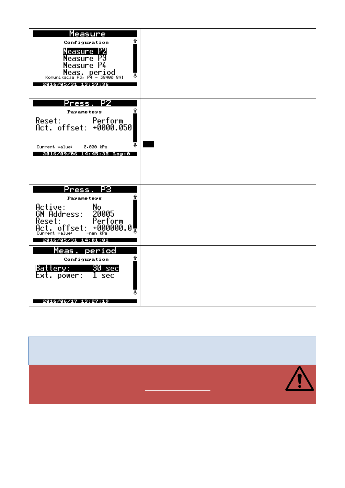
COMMON S.A. OPERATING INSTRUCTION CMK-03
Measure P2 – configuration of P2 converter
Measure P3 – configuration of P3 converter
Measure P4 – configuration of P4 converter
Meas. period – setting of the reading time periods for an external pres-
sure converters
Communication P3, P4: information about physical transmission pa-
rameters for ExtCPC port and connected to it CPC-03 converters.
The relative converter (gauge) has available functions:
Reset – there are two options:
Execute — the function reads current pressure value and set it
as actual offset.
Cancel — the function removes offset.
ESC button confirms changes after offset setting.
Actual offset – manually offset setting.
Current value – information about converter current value
In case of the absolute converter (abs) is displayed message and the
reset options are not available.
Press.P3 and Press.P4 menu are analogical to the Press.P2 menu.
Active – NO/YES – the function actives the ExtCPC port and reads data
from the external CPC-03 converters according to set time period.
GM Address – Gaz-Modem address. The default CPC-03 address is
always set as five last digits of the serial number.
Reset and Act. offset – described above
Current value — information about current value read from the converter
Meas. period — menu of the reading time period. The default values:
Battery – 30 seconds
Ext.power – 1 second.
The CMK-03 operates with the CPC-03 external converters with baud rate on level 38400 bits/s. The
CPC-03 converters baud rate should be set on mentioned value by means of dedicated configuration
program (e.g. CCTool) .
WARNING!
The proper operation between the external CPC-03 converter and the CMK-03 volume converter is possible from firmware version: CPC-03 nr v.13.11.27.08
The CPC-03 with older firmware will be not operate properly with the CMK-03
If there is an enter to the menu Measure P2, Measure P3, Measure P4 and there is active the absolute pressure
converter, the measuring period accelerates automatically to 1 second.
The CPC-03 firmware version is written in the converter name plate. It can be read in the Gaz-Modem 2/3 protocol or as an available parameter “wersja prog” in the DP table.
65
Page 66
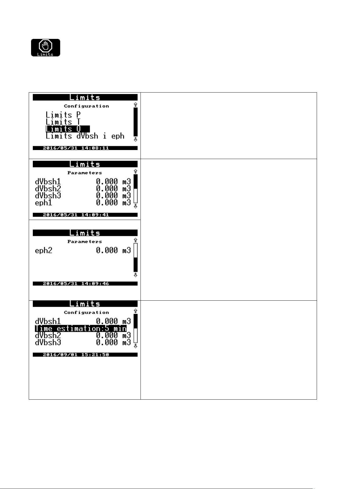
COMMON S.A. OPERATING INSTRUCTION CMK-03
Limits P – pressure limits setting
default set on zero (0); are disabled
Limits T – gas temperature limits.
default set on zero (0), are disabled
Limits Q – Qm and Q gas streams limits.
default set on zero (0), are disabled
Limits dVbsh and eph – counters limits of the hourly increases (to re-
duce the hourly consumption — “gas guard” function)
dVbsh1, dVbsh1, dVbsh1
There are 3 thresholds of the dVbsh hourly increase limit. The increase
of the volume summary counter in the basic and emergency conditions
from the beginning of the current clock hour.
The limits overflow occurs a alarms recording in the eph1, eph2 data
bases.
It is possible to set 2 limits of the eph estimated volume hourly increase.
The dVbs volume increase value estimated at the end of hour is based
on the dVbsh current usage from the beginning of the hour and current
Qb stream value.
The limits overflow will occur a alarms recording in the eph1, eph2 data
bases
estimation time– 0min/0…10min
Estimation time = 0 min — there is a disabled function of increase esti-
mation in the relation to dVbsh1 limit
“Estimation time” + “dVbsh1 limit” = “Gas guard” function
The both functions create the “Gas guard” function with the time predic-
tion on the set numbers of minutes. The dVbs volume increase value is
estimated on base of the current dVbsh usage from the beginning of the
hour and the current Qb stream value. The estimation time is set in the
“estimation time“ function.
If edVbsh estimated value is greater than programmed dVbsh1 limit it will
be recorded the proper alarm in the data base.
11.2.8 Limits and "gas guard” function
There is a menu of the limit settings.
The Limits are dedicated to
overflows registration (information is recorded in the Events)
registration of the double state outputs (OUT) activation — if such option has been previously defined.
To use the “gas guard” functionality as the control signal for the external automatic systems it is to be programmed selected OUT outputs. The OUT output should be activated with selected alarm, settable in the menu
Outputs. The alarm list is shown below:
[56] dVbsh1 limit exceeded
[57] dVbsh2 limit exceeded
[58] dVbsh3 limit exceeded
[59] eph1 limit exceeded
[60] eph2 limit exceeded
66
Page 67
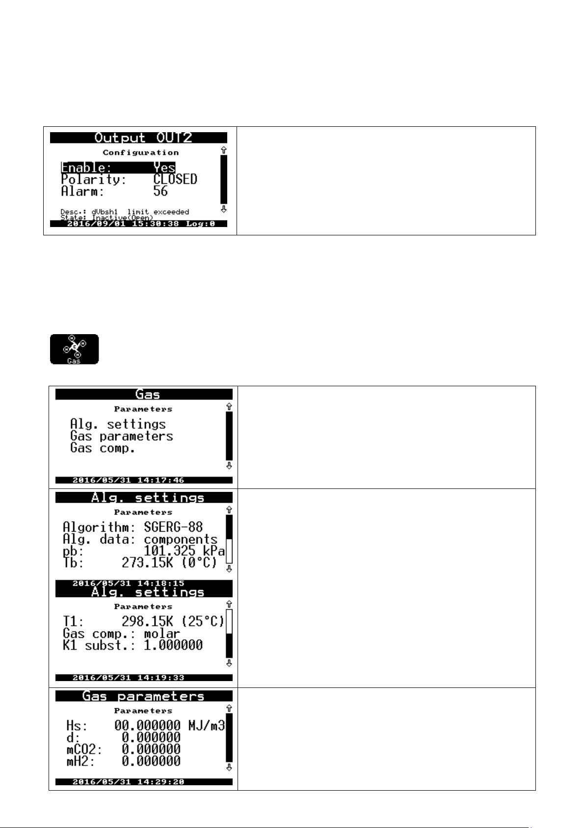
COMMON S.A. OPERATING INSTRUCTION CMK-03
The OUT2 output is dependent from the prediction of the overflow alarm
concern the set limit with the programmed estimation time.
Alg. settings – algorithm settings for the calculation of compressibility
coefficient
Gas parameters – the physical gas parameters: can be entered instead
of the gas composition
Gas comp. – percentage gas composition
Algorithm – the algorithm selection; possible settings: SGERG-88,
K1=const, AGA8-92DC
Alg. data – components/parameters: components are calculated from
the percentage gas composition: based on the entered parameters:
pb – basic pressure (1,01325 bar)
Tb – basic temperature (0, 15, 20°C)
T1 – reference temperature for the calculation of the heat combustion (0,
15, 20, 25°C)
Gas comp.– molar/volume; information regarding to the entered per-
centage gas composition: molar or volume?
K1 subs. – compressibility coefficient alternative value , default set on
1.0
Gas parameters:
Hs – heat combustion
d – density in the basic conditions
mCO2 – molar participation of the carbon dioxide
mH2 – molar participation of the hydrogen
[66] next dVbsh1 limit exceeded (with prediction function – an overflow will occur in “n” minutes)
The example:
If the estimated increase values will start to decrease after an over crossing the limits and the values will fall down
below the limits, then the alarms will be ended and the OUT output which was activated by this alarm, will be
switch in the inactive state.
The “Gas guard” function works in the same way both on the battery and on external power supply.
11.2.9 Gas
The “Gas” menu is a programming functions for the gas parameters. The gas parameters are nec-
essary to the calculation of compressibility coefficient. Menu consists of a three functions:
67
Page 68
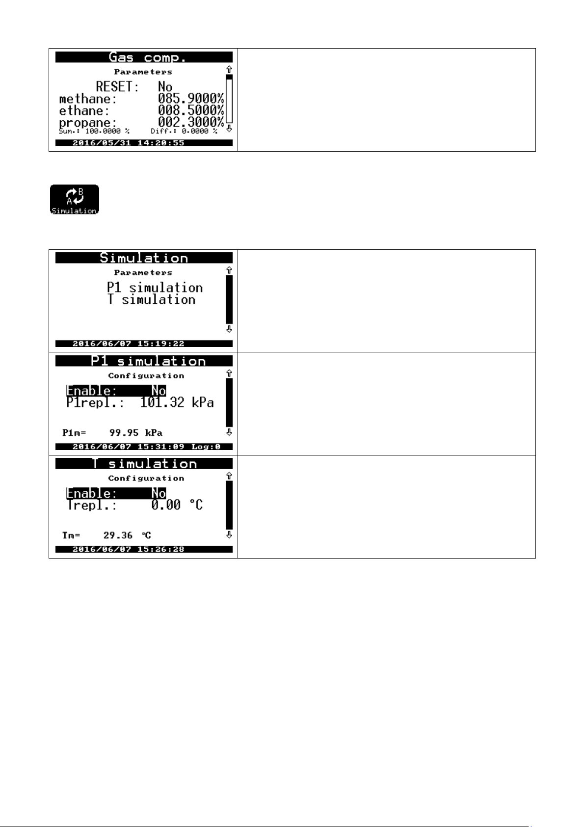
COMMON S.A. OPERATING INSTRUCTION CMK-03
The percentage gas composition settings.
There is an implemented ‘reset’ function (two options NO/YES) which
reset all of the components values.
While entering there is displayed the sum of the actually entered components and their difference to 100%. The components sum has to be equal
100%.
P1 simulation – P1 pressure simulation settings
T simulation – T temperature simulation settings
Enable: NO/YES — activation / deactivation of the:
pressure simulation
converter operation with the P1repl substitute value
P1repl – P1repl. value setting
P1m – the current pressure value measured by the converter.
Enable: NO/YES –— activation / deactivation of the
temperature simulation
converter work with the Trepl substitute value
Trepl – Trepl. value setting
Tm – current temperature value measured by the converter.
11.2.10 Simulation
There are settings of the compressibility coefficient of Trepl temperature and P1repl pressure sub-
stitute values. The substitute values are used when there is no measurement result (states such as: measuring
ranges overflows or converter damage). The calculated volume is counted to the Vbe emergency counter.
There is possible to activate manually the substitute values. This functionality allows for the periodical checking the quality of temperature and pressure measurements in the converter which is in usage. The following conditions should be assure in case of the p1 pressure converter:
to program P1repl pressure substitute value (e.g. value which is close to pressure value at the actual mo-
ment in the piping).
to set Enable: YES. From this moment the CMK-03 will count the volume to the Vbe counter and the re-
spectively alarm will be recorded in MID alarms and Events data bases.
to connect a calibrator to the CKMT three way valve and to set a lever in the proper position what will con-
nect p1 converter with the calibrator.
the current pressure measured value can be observed on the screen in P1m position. If there is defined
control pressure value it is possible to observe an indications from the pressure converter.
WARNING!
the selection of the pressure or temperature simulation on the battery working mode, causes automatically acceleration of the execution period to 1 second. This status is kept until to switch off the
display backlight or until to exit from the simulation settings menu.
the CKMT 3 way valve should be leave in the proper position after finishing of the control measurement
68
Page 69
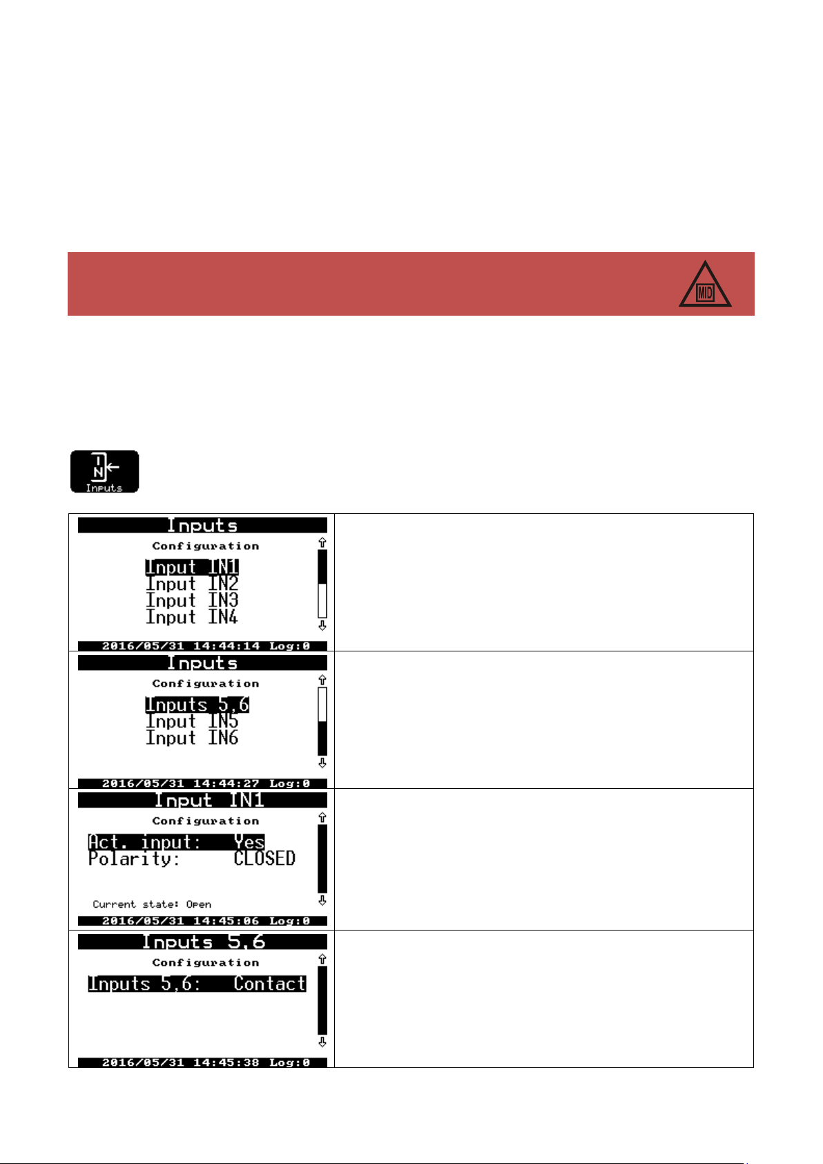
COMMON S.A. OPERATING INSTRUCTION CMK-03
The measurement of t temperature or p1 pressure is covered by the control of the metrological law. There is no possibility to adjust the converter indications in the device which is in
usage. The CMK-03 is sealed with the metrological marks after the Primary Verification.
The converter is equipped in the 6 double-state IN inputs.
Inputs IN1…IN4 are always Type ‘Contact’ (dedicated to the operation
with “potential free” connectors Type: ‘Contact’, ‘End-contact’ or ‘Opencollector’.
Inputs IN5 and IN6 can be configurable as ‘Contact’ Type or ‘NAMUR’
Type
There are two configuration options for the Inputs ‘Contact’ Type
Act. inputs – YES/NO – an activation of the input and alarm registration
Polarity – (CLOSED / OPEN).
‘Closed’ activates the alarm in case of short circuit of input.
‘Open’ activates the alarm in case of electrical opening of input
There is presented a physically Current state of the circuit in the line
below
Inputs 5, 6 — there are two options of the inputs standards
CONTACT — default set
NAMUR — it is necessary to provide an external power supply
of the NAMUR circuits and converter power supply (clamp +8V
and V+ on terminal strip COM3)
the option: Enable: set as “NO” in the P1 simulation menu. The converter will return to the normal working
mode with a normal measuring period.
The above method is analogical in case of the temperature control. There is possible as follows:
to observe the indications of the temperature measurement at the moment of manually temperature set
(the thermometer is placed in the calibrator, in the reference temperature field).
to control the thermometer resistance which is placed in the reference temperature field after cables dis-
connection of the PT1000 (the manufactured, security seal has to be removed)
to control the converter indications by using the calibrator/simulator of the PT1000 thermometer in the 4-
cables measuring mode.
The CMK-03 converter assure an accuracy of measurements with the limiting error in the acceptable MPE range
during all entire operating time.
The actions described above are only a control checking, which can be contained as a recommendation in the
Manual and Maintenance Instruction of the measuring stations.
11.2.11 Inputs IN
There are settings of the double-state signaling inputs.
69
Page 70
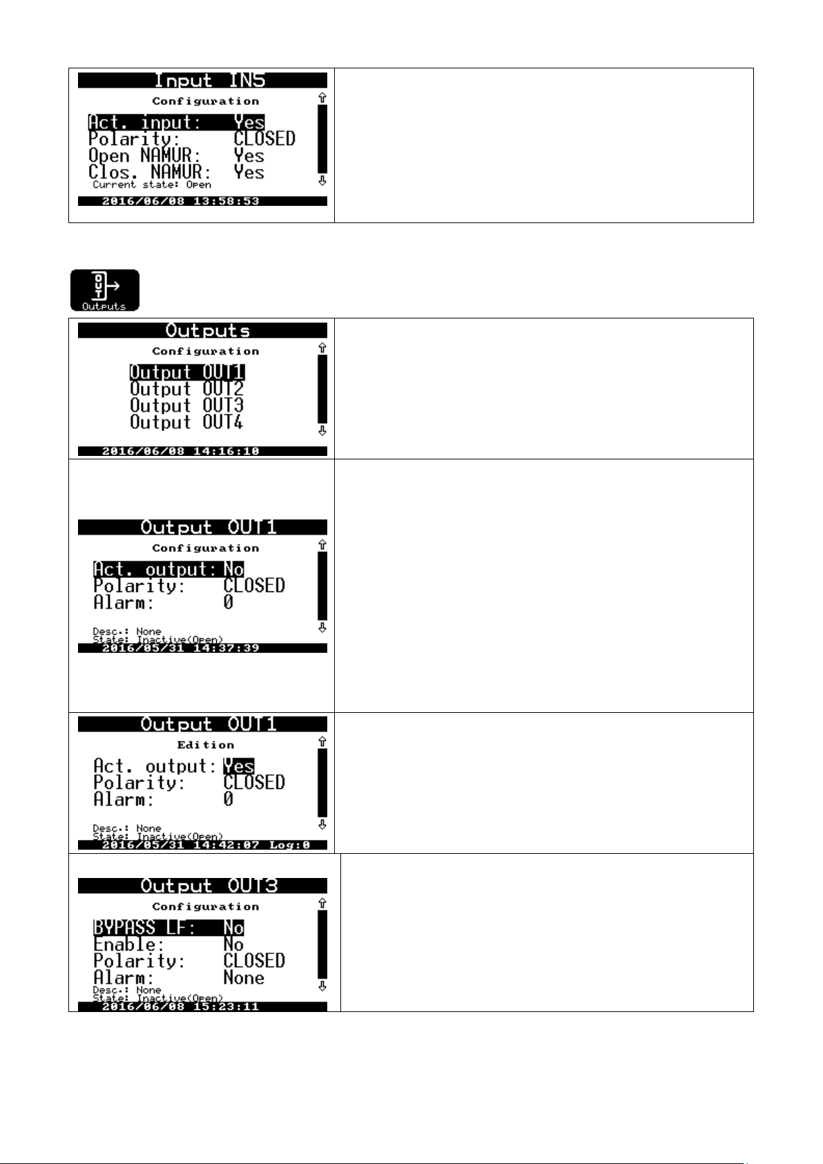
COMMON S.A. OPERATING INSTRUCTION CMK-03
The input activation and polarity setting of the IN5 and IN6 inputs is analogical for the NAMUR operating mode as for the ‘Contact’ Type operating mode.
There are two options available:
Open NAMUR – YES / NO – the alarm is detected and registered when
there is a breaking of the electrical circuit of NAMUR transmitter/input
Clos. NAMUR – YES / NO – the alarm is detected and registered when
there is a short circuit of the electrical circuits of NAMUR transmitter/input
There are four double-state OUT outputs ‘Open-collector’ Type.
The configuration should be started from output selection.
There is possible as follows:
to activate the output
to set the output polarity
to select activation alarm
to activate ‘LF bypass’ or ‘HF bypass’ function.
Act. outputs – YES / NO; activation / deactivation of the output functionality
Polarity – (CLOSED / OPEN) – the selection of the output polarity (if the
function is active).
“CLOSED” — the short circuit of output clamps on the moment of logical
output activation (e.g. overflow of the pressure limit).
Option can be used for signal negation (e.g. to cause the output open
circuit if there is an overflow alarm of the set volume increase.
Alarm – (0) alarm number which causes the output activation.
There are presented in the lines below as follows:
Desc. — alarm description
State — the current output status
If the selected alarm is active , the output status will be conform with
polarity setting.
Example:
OUT1 output enabled
the polarity of activated output closed what means normally
open circuit.
In case of the p2 limit overflow, the OUT1 output circuit will be closed
during a all time of the alarm.
There is a LF bypass function in the OUT3 output. If this option is active
(set on: YES) the current status of LF input will be the same on the
double-state OUT3 output. This signal can be used for an external automatic systems. The activation of the LF bypass function does not
affect on the incoming LF signal and its counting and converter operating.
If there LF bypass function is activated, the alarms function does not
work and are unavailable on the OUT3 output.
11.2.12 Outputs (OUT)
There are settings of the double-state signaling outputs.
70
Page 71
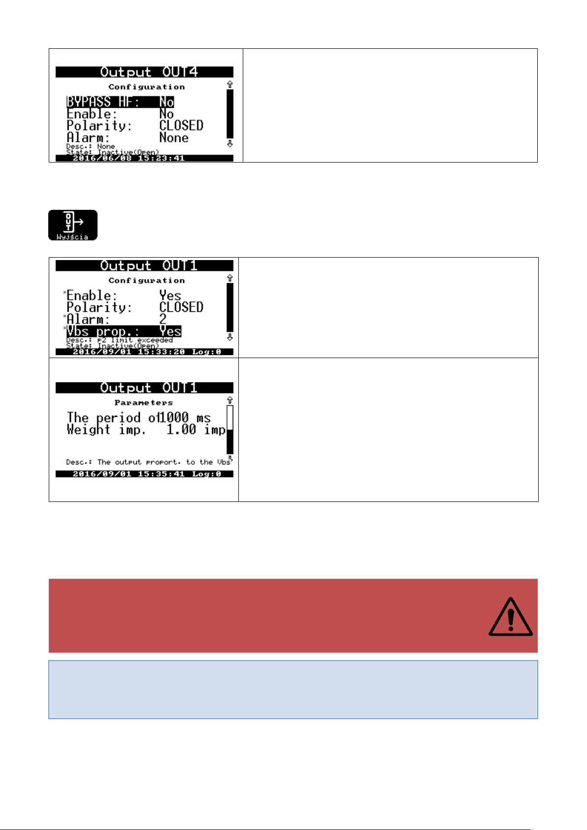
COMMON S.A. OPERATING INSTRUCTION CMK-03
There is HF bypass function in the OUT4 output. If this option is active
(set on: YES) the current status of the converter HF input will be the
same on the double-state OUT4 output. There is also necessary to
provide the proper external power supply to the COM3 port (V+ and
+8V). This signal can be used for an external automatic systems. The
activation of the ‘bypass’ function does not affect on incoming HF signal
and its measurement.
If the HF ‘bypass’ function is activated, the alarms function does not
work and are unavailable on the OUT4 output.
Vbs prop. – YES / NO. Menu Settings Outputs OUT1
The default setting (NO) deactivates the function. If the user want to activate the pulse output (proportional to the Vba increase), the Vbs.prop
parameter need to be set on: YES.
The changes should be saved.
There will be activated 2 next parameters:
Imp. period – 1000ms pulses will be generated with the selected
period. fullness coefficient is equal 50%. The possible selection of the
period as follows: 200, 400, 600, 800, 1000, 1200, 1400, 1600, 1800,
2000ms.
Imp. weight (pulse value) – 1.00 m3 the value setting of the output
pulse.
The pulse will be generated with every cycle of volume increase value,
which is defined on the OUT output.
The possible range of programmed weight – any number in the format
XXXX.XX m3
WARNING!
The pulse period and the pulse value of OUT1 output should be set accordingly to the real
occurring basic gas streams (depending from: size of gas meter, pressure, temperature),
so as the OUT1 output will be able to generate an pulses proportional to the Vbs, between
next incoming pulses from the gas meter (the volume increases).
If the Vbs volume increase is faster than possibility of pulse generation, the CMK-03 will buffer ongoing the information about surplus of pulses which need to be generate and develops them successively in the form of the cyclic pulses on the output. The all outstanding pulses will be generated if
the stream value will decrease.
11.2.13 Odorizing unit control, OUT1 output proportional to the Vbs
The OUT1 output can generates pulses and this function can be used to control of the gas odorizing
unit. The generated pulses have programmed parameters which are proportional to the Vbs increasing summary basic volume (Vbs = Vb + Vbe).
The polarity setting (CLOSED / OPEN) is available in the output configuration. The alarm settings are not important. The alarms do not interfere (even if was set) on the output status (configured as the output proportional to
the Vbs).
If the Vbs increase is greater than set pulse value, it will be generated the number of pulses (t ype integer) on the
output. This number results of the multiple pulse value contained in the Vbs increase value.
The used algorithm provides an effect of the unlimited buffer — it will be not missed any of the pulses which
should be generate.
The odorizing unit control of the output which is proportional to the Vbs increase operates on the same rules both
on battery and on external power supply. The functionality is maintained also for the LF and HF signal source of
the gas meter.
71
Page 72
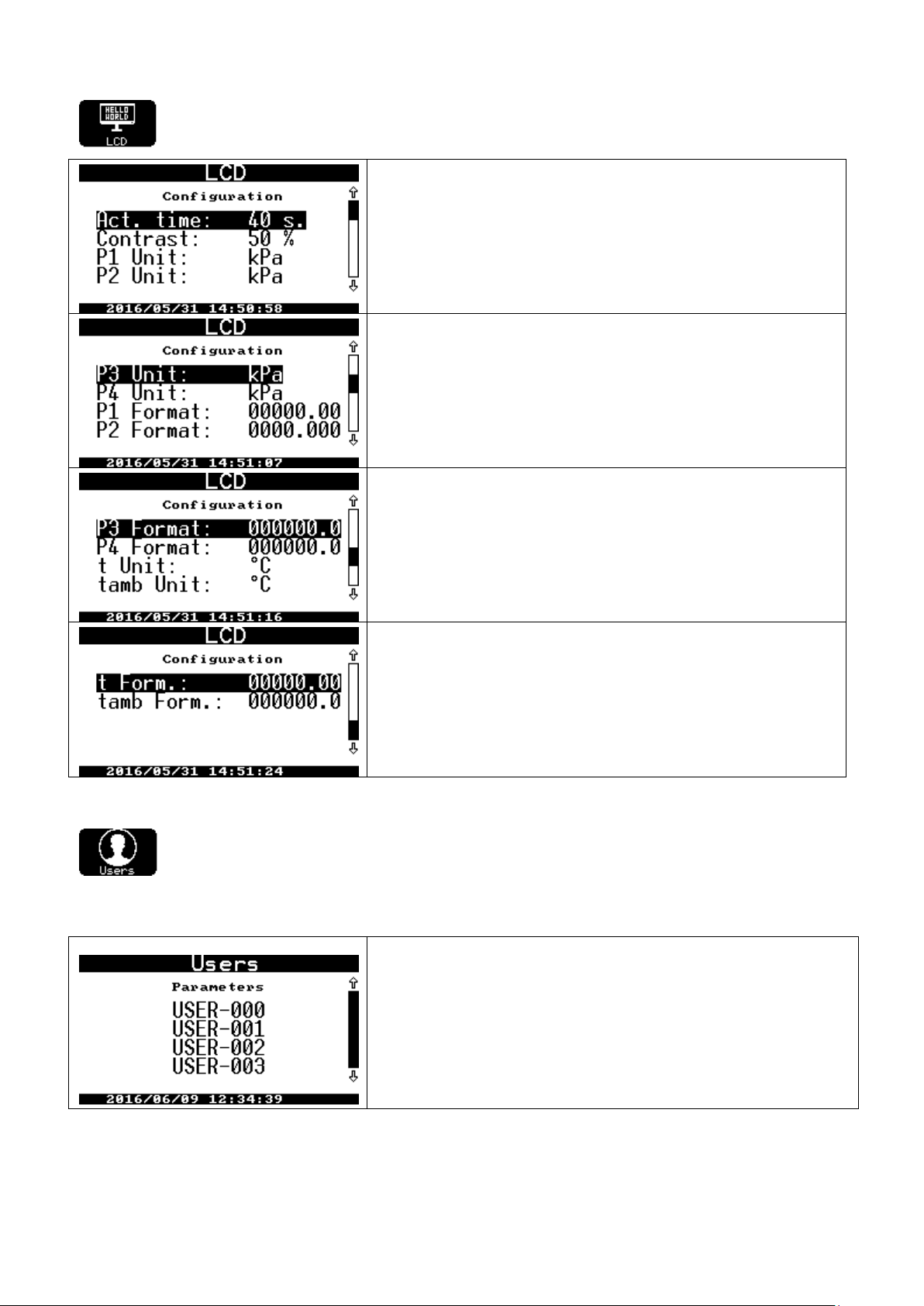
COMMON S.A. OPERATING INSTRUCTION CMK-03
Act. time – activity time in the battery working mode
Contrast – display contrast
P1…P4 Unit – selection of the pressure unit. Available units: kPA, MPa,
psi
P1…P4 Format – format of the pressure value (the number of digits be-
fore point and after point)
The unit format should present 5 or 6 significant digits of the measured
value.
t Unit – unit of gas temperature. Available units: °C, K, °F, °R
tamb Unit – unit of the housing temperature. Available units: °C, K, °F, °R
t Form. – format of the gas temperature value (the number of digits before
point and after point)
tamb Form. – format of the housing temperature value (the number of
digits before point and after point)
The unit format should present significant digits of the measured value.
users list
11.2.14 LCD
The LCD settings such as: contrast, activity time of the display, unit format of the measured figures.
11.2.15 Users
The user setting menu:
user passwords
user permissions to modify the converter parameters
72
Page 73
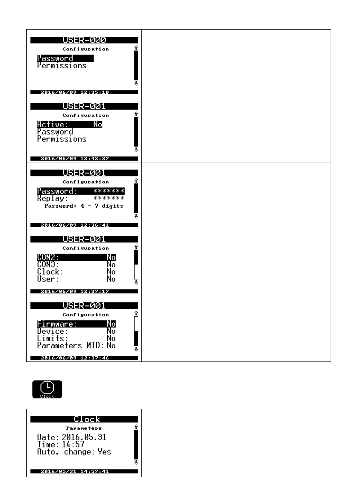
COMMON S.A. OPERATING INSTRUCTION CMK-03
The “USER-000” (default) user is active with password “0000” (default). This
user can not be deactivated by other user both from the local level and from
the authorized level. It is impossible to disable the ‘USER’ and ‘Firmware’
permissions of the USER-000.
USER-001, USER-002, USER-003 – users are inactive (default).
The first activation of them is possible from the authorization level by the
USER-000.
PASSWORD – password modification requires user login and double entering of the new password. The password contains 4-7 digits.
Setting of the user permissions:
COM2 – parameter connected with the transmission of COM2 port
COM3 – parameter connected with transmission of COM2 port
Clock – parameter connected with time, date, time changing
User – users activation, changing of the password and permissions
Setting of user permissions:
Firmware – firmware upgrade
Device – technological parameters of device
Limits – limit values of alarms
Parameters MID – parameters under metrological control
Data – setting of the calendar data
Time – setting for current time of RTC clock
Auto. change – disable / enable for automatically time switching sum-
mer/winter. Available values: YES / NO.
11.2.16 Clock
The clock menu: date, time, time auto change (summer/winter).
73
Page 74

COMMON S.A. OPERATING INSTRUCTION CMK-03
12. Extended functionalities settings
The CMK-03 volume converter has extended functionalities which are used in the special issues. These functions
are not presented on the display and are available in the Gaz-Modem2/3 protocol via remote access mode and
also visualized in the CCTool computer program.
12.1 Summary alarms
There are two options to configure the summary alarms: A summary alarm and B summary alarm. The user
can select any of available, single alarm (from the group of the permanent alarms) which is a part of summary
alarm. The summary alarm will end if there will be not active any of the alarms from the selected group. During
the summary alarm, the occurrence of the additional configured alarm does not cause the opening of the new
summary alarm.
The summary alarms are registered as a permanent alarms in the bases: Alarms and Events. The alarms are
additional possibilities for automatic and telemetric systems to monitor the gas station.
The status of summary alarm can activate the selected signaling output. The OUT outputs configuration method
is available from the level of CCTool program, and is described in the part 11.2.12 OUT Outputs.
The summary alarms configuration is based on “drag and drop” interface function in the CCTool program. The
access to the configuration menu is available regarding to the path: Configuration Alarms group indicator
of the A summary alarm, or B summary alarms.
The configuration of the summary alarms in the Gaz-Modem 2/3 protocol is based on the proper setting of DP
Table parameters as a bitmap which relates to the proper product codes of the ZD Table.
The DP table parameters which are used to configure A Summary Alarm:
al_GA0 binary vector which activates summary alarm type A for alarms from 0 till 31
al_GA1 binary vector which activates summary alarm type A for alarms from 32 till 63
al_GA2 binary vector which activates summary alarm type A for alarms from 63 till 95
al_GA3 binary vector which activates summary alarm type A for alarms from 96 till 127
The DP table parameters which are used to configure B Summary alarm:
al_GB0 binary vector which activates summary alarm type B for alarms from 0 till 31
al_GB1 binary vector which activates summary alarm type B for alarms from 32 till 63
al_GB2 binary vector which activates summary alarm type B for alarms from 63 till 95
al_GB3 binary vector which activates summary alarm type B for alarms from 96 till 127
To disable the functionality of summary alarm it should be proceed as follows:
the selected alarm should be removed from the list
the vectors which activate specific summary alarm, should be reset on zero.
12.2 Control of the gas meter HF/LF constant error.
To enable the control functionality of the gas meter HF/LF constant error value it should be:
to equipped a gas meter in two types of transmitters LF and HF;
to switch Qm stream source on “LF+HF” (parameter ‘Qm src’ in DP Table);
to assure a external power supply V+ of converters, and power supply of NAMUR +8V;
to set HF transmitters constant (the number of HF pulses relating to one cubic meter – impHF parameter in
DP Table) read from the name plate of controlled gas meter.
to set possible percentage error limit of the transmitter HF constant (eHFdl and eHFgl in DP Table);
The percentage error is calculated between a counted constant and the constant written on the name plate (eHF
parameter in the DP Table) by every LF pulse.
If there is an limits overflow, it will be recorded the alarm (code 63) and displayed the message “eHF limit ex-
ceed”. This alarm code can indicate for example: a gas meter damage, or a transmitter damage, or improper
position of the HF transmitter, etc.
To disable the control functionality of constant error value of the gas meter, the value of error limits should be set
on zero (0).
The availability of HF transmitter constant:
impHF/LF parameter in DP Table [imp/m3].
74
Page 75

COMMON S.A. OPERATING INSTRUCTION CMK-03
the CCTool program: bookmark Configuration Gas meter indicator HF transmitter constant
[imp/m3]
The availability of the limits errors of HF constant:
eHFdl [%] and eHFgl [%] parameters in the DP Table — accordingly top and bottom limit
the CCTool program: bookmark Configuration Gas meter indicator error limit of the HF constant
12.3 Operating below Qmin of gas meter – operating range: QmSTOP <–> QmMIN.
The configurable QmStop parameter describes a stream value at which the gas meter will stop.
If the current Qm stream value will be in the range between programmed values of QmStop and QmMin, the
volume converter will record the permanent alarm with code 62 and display the message “QmStop < Qm <
QmMin”. If the stream value will return to the proper, operating range between QmMin and QmMax, or from zero
to QmStop, the alarm will be close.
The alarm contains information as follows:
Qm stream from the beginning of alarm;
actual QmStop value;
p1, t, tamb, status of the double-state Inx inputs;
Vmk, Vbk, Ek counters from the beginning of alarm;
Vmk, Vbk, Ek counters from the end of alarm;
The reading and analysis of this parameter provides information about date and time when the gas meter worked
at the stream below bottom measuring range.
To disable a functionality of the alarm registration in the operation range QmStop <–> QmMin, the QmStop parameter is to be set on value equal with the bottom measuring range of gas meter.
To disable a functionality of the alarm registration for the range and QmStop overflows, the limits parameters are
to be set on zero (“0.00”).
12.4 LCD power supply
There is possible to configure a LCD setting and LCD backlight in case of the service action, connection or disconnection of the external power supply, inactive time and energy consumption etc, what determinate the energy
usage.
The settings availability in the CCTool programs: bookmark Configuration LCD.
There are three most typical LCD operating modes:
DEFAULT – LCD activation without backlight, turn off on the battery after time
ECONOMIC – LCD activation without backlight, the external power supply does not turn on the LCD
CONFORT – LCD activation with backlight in every power supply mode, readability and availability
There is possibility to set the LCD individually by means of the options form mentioned above modes:
automatic LCD backlight on the battery supply
automatic LCD backlight on the external power supply
LCD always turned-on on the external power supply
activate the LCD after detection of the external power supply
automatic LCD backlight after detection of the external power supply
deactivate LCD if there is a loss of the external power supply
LCD activity time on the battery supply
LCD activity time on the external power supply
12.5 Reserve1 configuration in the Gaz-Modem1
The CMK-03 operates a functions of the Gaz-Modem1 protocol where the ‘rez1’ position informs about the pressure value of external converter (P2, P3 or P4) in the read frame of current data. To define the number of used
converter is to be set the ConfigRez1 parameter in DP Table — possible values: 1, 2, 3.
In the CCTool program: bookmark Configuration General indicator rez1 configuration in GM1.
75
Page 76

COMMON S.A. OPERATING INSTRUCTION CMK-03
12.6 OPTO-GAZ port activity time
The OPTO-GAZ transmission port is activated automatically, after a placement of the optical head. The port is
automatically deactivated after the period of inactive time (no transmission). The automatic deactivation is applied
because of:
battery saving;
prevention against permanent blocking of the COM1 (TUCHEL) port through the OPTO-GAZ interface;
The deactivation is realized by means of the parameter:
OptoExpireTime [s] — in the DP Table
in the CCTool program: Configuration COM ports OPTO-GAZ indicator OPTO-GAZ activity
time.
13 Remote control of the CMK-03 converter, Users, authorization
The CMK-03 is equipped in a four digital communication ports which assures reading as follows:
current measured data
registered data
configuration data
registered alarms and events.
The transmission is provided by the selected Gaz-Modem 1/2/3 or MODBUS protocols. The modification of configuration parameters is possible by means of the Gaz-Modem 2/3 protocol after an authorization with user ID
and correct password.
The data transmission can be realized with any of program which is compatible with the selected protocol. The
Gaz-Modem 2/3 protocol is standardized and described in the Factory Standard ZN-G-4007 and in the standard
ST-IGG-0207.
The CCTool program is dedicated to service and transmission with CMK-03. The program is provided and supported by COMMON S.A.
13.1 CCTool configurator
The CCTool is a freeware program provided by COMMON S.A. which is dedicated to configure, to data reading
and to manage of the CMK-03. The program requires Windows XP SP3 or higher version of operating system
with installed Microsoft.NET Framework Version 2.0 and Microdsoft.NET Framework 4.0 to works correctly.
Program is free to download from the web site www.common.pl.
The connection with the CMK-03 is realized as follows:
by means of the communication ports (COM1, COM2, COM3) which operates in the RS-GAZ2 standard
(intrinsically safe version of RS-485 interface).
by means of the optical head COG-USB-03 manufactured by COMMON S.A (connected to the OPOTO-
GAZ port)
The COG-USB-03 optical head is available as additional accessories – look at the Table 2.1 Additional Accessories.
The example screenshot of the CCTool menu is presented below:
76
Page 77

COMMON S.A. OPERATING INSTRUCTION CMK-03
The CCTool program assure as follows:
communications by using selected transmission channel: serial port, Internet , modem
parameters and proprieties presentation
configuration of all parameters used to configure the CMK-03
diagnostic and alarms reading
current data reading
registered data reading
updates for internal firmware of the device
The CCTool program has a option which automatically update the system version. Updates are
checked and downloaded via Internet from the server of Common S.A. Company.
The external power supply is not required if the data transmission is realized by means of the OPTOGAZ. The reading is possible both on the battery and on the external power supply working mode.
The detailed information about the CCTool are described in menu: Program \ Help and also on website
www.common.pl
13.1.1 Connection by using COGUSB-03 interface
The COGUSB-03 optical interface assures connection between PC computer and the CMK-03, which is located
in the explosion hazard area.
The data exchange between read device and COGUSB-03 optical head is realized via IR radiation. The optical
head should be placed on OPTO-GAZ port of the read device by using built-in permanent magnet. The USB terminal is connected to the PC computer and work as 1.1 or 2.0 standard.
The optical head and the holding place are presented in Figure 12.1. The COGUSB-03 is available as an additional accessory – see Table 2.1.
Figure 13.1 The placement of the OPTO-GAZ optical head
77
Page 78
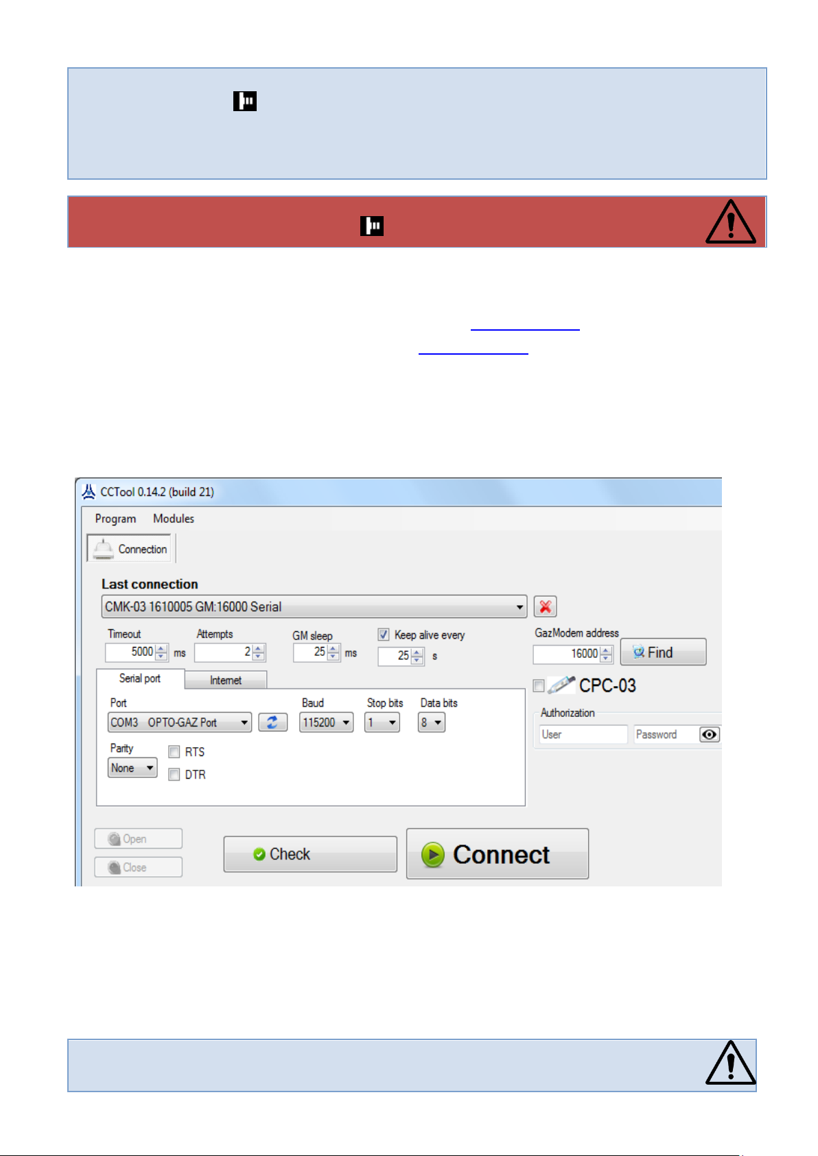
COMMON S.A. OPERATING INSTRUCTION CMK-03
The OPTO-GAZ port is automatically active at the moment of optical head placement. The connection is
confirmed with flashing icon, which is visual on the top bar of LCD main screen.
The port is active during a transmission time. If there is no transmission, the port remains active according to the defined time in the time period option (‘OPTO-GAZ activity time’ parameter). The parameter is
default set on 600 seconds.
The usage of the OPTO-GAZ port blocks transmission on the COM1 (TUCHEL) port during
activity time what is indicated with flashing icon on the LCD.
If the CMK-03 is ready to work, the owner / installer is obligated to change the default password responsible for the authorization, acknowledgment and parameter modification.
The reading and configuration can be realized by means as follows:
to connect interface to the USB port of PC computer
to install the COGUSB-03 drivers (available on the website: www.common.pl)
to start the CCTool program (available on website: www.common.pl)
to select COM port from ports list, with description COGUSB-04<->OPTO-GAZ (the same as in Figure be-
low).
to select the baud rate according to the OPTO-GAZ port settings (menu: Settings COM portsOPTO-
GAZ on the converter display).
to select option/button ‘Connect’
13.1.2 Users and authorization
The “User 0” account is default active in the CMK-03 (user ID:”USER-000”, password: “0000”). The permission
level of the “User 0”, allows for the modification all group of the parameters (COM ports, clock, users permissions,
firmware, device manage, settings for limits and MID parameters).
78
Page 79
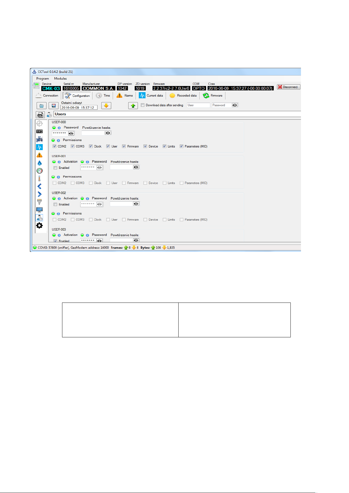
COMMON S.A. OPERATING INSTRUCTION CMK-03
to read
to modification
to registration with a registration pe-
riod
daily registered data
MID alarms
Events
The “User-000” can activate next user and set his password and level of permission. The identifiers (ID) for new
activated users: USER-001, USER-002 USER-003 are not modifiable. The password can be the numbers with
length from 4 till 7 digits.
The example of the CCTool screenshot with configuration of the user account is presented below:
The authorization is realized from local service level, after ID selection and the password entering (see part
11.2.3). The modification of user accounts from LCD menu level is described in the part 11.2.14.
14 Data registration, reading and configuration in the telemetric systems
The CMK-03 controls 348 gas parameters. Data are classified as follows:
The all types of data are directly available in device menu (see part 11 – Local service).
There is possible to read and register the data via a telemetric systems by means of Gaz-Modem 1/2/3 protocol.
The current data can be read by means of the Gaz-Modem1/2/3 or Modbus RTU protocols.
The parameters modification and reading of registered data is possible by means of the dedicated CCTool configuration program or other program which is able to read the GMWin (see part 12 Remote control of the CMK-
03 converter, users, authorization).
14.1 Registered data
The CMK-03 volume converter has 3 type of the registered data:
registered data with the registration period (1; 2; 3; 4; 5; 6; 10; 12; 15; 20; 30; 60) min
daily registered data
Events and MID alarms (the details are described in the part 9 MID alarms and part 10 MID interferences
(configuration changes)).
79
Page 80

COMMON S.A. OPERATING INSTRUCTION CMK-03
WARNING:
The beginning of the gas day is defined as the ‘gas day’ parameter in the CMK-03 menu or as
the ‘HD’ parameter in the DP Table.
L
P
number
In DP
table
Gaz-
Modem
protocol
name
Description
Data
format
Parameter
registered
with Regis-
tration
period
daily registered param-
eter
1 0 p1
Gas pressure p1
short
real
2 1 t
Gas temperature
short
real
3 4 Vb
Volume counter in basic conditions
uint64
4 5 Vbe
Volume counter in basic conditions In emergency state
uint64
5
10
Vbs
Summary counter Vb+Vbe
uint64
6
11
p2
Gas pressure p2
short
real
7
12
p3
Gas pressure p3
short
real
8
13
p4
Gas pressure p4
short
real
9
15
p1peakMin
Minimum p1 value in registration period
short
real
10 16
p1peakMa
x
Maximum 1 value in registration period
short
real
1
1
17
p1MinD
Minimum p1 value in gas day
short
real
1
2
18
p1MaxD
Maximum p1 value in gas day
short
real
13 20
p2peakMin
Minimum p2 value in registration period
short
real
14 21
p2peakMa
x
Maximum p2 value in registration period
short
real
1
5
22
p2MinD
Minimum p2 value in gas day
short
real
1
6
23
p2MaxD
Maximum p2 value in gas day
short
real
17 25
p3peakMin
Minimum p3 value in registration period
short
real
18 26
p3peakMa
x
Maximum p3 value in registration period
short
real
1
9
27
p3MinD
Minimum p3 value in gas day
short
real
2
0
28
p3MaxD
Maximum p3 value in gas day
short
real
21 30
p4peakMin
Minimum p4 value in registration period
short
real
22 31
p4peakMa
x
Maximum p4 value in registration period
short
real
2
3
32
p4MinD
Minimum p4 value in gas day
short
real
2
33
p4MaxD
Maximum p4 value in gas day
short
14.1.1 Data registered with registration period and daily registered data
The registered data with the registration period (1; 2; 3; 4; 5; 6; 10; 12; 15; 20; 30; 60) are recorded in the internal non-volatile, rotary memory. The capacity of base is prepared for 30 000 of records.
The registration period is available as the “Regist Period” option in LCD menu, and as the dtau parameter in the
DP Table. If the registration period is set on 10 minutes, the oldest data will be overwrite after 167 days.
The daily registered data are recorded in the non-volatile, rotary data base. The base capacity is calculated on
the 2200 days (6 years).
The reading of the registered data is possible locally from the menu (see part 11.1.2) or by means of Gaz-
Modem 1/2/3 protocols via one of three communication COM (RS-GAZ2) ports or one OPTO-GAZ port.
The list of the registered parameters in presented in the Table 14.1.
Table 14.1 List of the DP parameters
80
Page 81

COMMON S.A. OPERATING INSTRUCTION CMK-03
4
real
25 60
tpeakMin
Minimum t value in registration period
short
real
26 61
tpeakMax
Maximum t value in registration period
short
real
2
7
62
tMinD
Minimum t value in gas day
short
real
2
8
63
tMaxD
Maximum t value in gas day
short
real
29 69
tamb
Ambient temperature
short
real
3
0
70
tambMinD
Minimum ambient temperature value in gas day
short
real
3
1
71
tambMaxD
Maximum ambient temperature value in gas day
short
real
32 72
Uzas
System supply voltage
short
real
3
3
73
UzasMinD
Minimum supply voltage in gas day
short
real
3
4
74
UzasMaxD
Maximum supply voltage in gas day
short
real
35 75
Urtc
RTC clock supply voltage
short
real
3
6
76
UrtcMinD
RTC clock minimum supply voltage in gas day
short
real
3
7
77
UrtcMaxD
RTC clock maximum supply voltage in gas day
short
real
38 159
Vm
Gas volume counter in measuring conditions
uint64
39 225
E
Energy counter
uint64
40 226
Ee
Energy counter in emergency state
uint64
41 227
Es
Summary counter E+Ee
uint64
42 236
dVm
Increase in Vm in registration period
uint64
4
3
238
dVmD
Increase in Vm in gas day
uint64
44 239
dVb
Increase Vb in registration period
uint64
45 242
dVbe
Increase Vbe in registration period
uint64
4
6
244
dVbeD
Increase Vbe in gas day
uint64
47 245
dVbs
Increase Vbs in registration period
4
8
247
dVbsD
Increase Vbs in gas day
uint64
49 248
dE
Increase in E in registration period
uint64
5
0
250
dED
Increase in E in gas day
uint64
51 251
dEe
Increase in Ee in registration period
uint64
5
2
253
dEeD
Increase in Ee in gas day
uint64
53 254
dEs
Increase in Es in registration period
uint64
5
4
256
dEsD
Increase in Es in gas day
uint64
55 296
Vb_dbl
Volume counter in basic conditions
long real
56 297
Vbe_dbl
Volume counter in basic conditions In emergency state
long real
57 298
Vbs_dbl
Summary counter Vb+Vbe
long real
58 299
Vm_dbl
Gas volume counter in measuring conditions
long real
59 300
E_dbl
Energy counter
long real
60 301
Ee_dbl
Energy counter in emergency state
long real
6
302
Es_dbl
Summary counter E+Ee
long real
81
Page 82

COMMON S.A. OPERATING INSTRUCTION CMK-03
1 62
303
dVm_dbl
Increase in Vm in registration period
long real
6
3
305
dVmD_dbl
Increase in Vm in gas day
long real
64 306
dVb_dbl
Increase in Vb in registration period
long real
65 309
dVbe_dbl
Increase in Vbe in registration period
long real
6
6
311
dVbeD_dbl
Increase in Vbe in gas day
long real
67 312
dVbs_dbl
Increase in Vbs in registration period
long real
6
8
314
dVbsD_dbl
Increase in Vbs in gas day
long real
69 315
dE_dbl
Increase in E in registration period
long real
7
0
317
dED_dbl
Increase in E in gas day
long real
71 318
dEe_dbl
Increase in Ee in registration period
long real
7
2
320
dEeD_dbl
Increase in Ee in gas day
long real
73 321
dEs_dbl
Increase in Es in registration period
long real
7
4
323
dEsD_dbl
Increase in Es in gas day
long real
WARNING:
The occurrence of the ‘Event’ or ‘Alarms’ may cause the stop of volume counting to Vb counter and start the
estimation to Vbe emergency counter.
Event
code
Description
Counting
into Vbe
Event
code
Description
Counting
into Vbe
0
CMK-03 start
33
5N signaling error
1
p1 limit exceeded
34
6N signaling error
2
p2 limit exceeded
35
p1 outside method's scope
3
p3 limit exceeded
36
t outside method's scope
4
p4 limit exceeded
37
p1 transducer malfunction (MID:3)
5
t limit exceeded
38
t transducer malfunction (MID:4)
6
p1 range exceeded (MID:0)
39
K1 alarm replacement value
(MID:5)
7
p2 range exceeded
40
p1 replacement value enabled
(MID:6)
8
p3 range exceeded
41
t replacement value enabled
(MID:7)
14.1.2 Events
The following issues are registered as ‘Events’ in the CMK-03:
change of the measured parameters over set limits
occurrence of the outputs signals
configuration change
occurrence of the errors for calculating parameters
firmware change.
The ‘Events’ are recorded in the internal rotary, non-volatile data base with capacity on the 1024 position.
The reading of the ‘Alarms’ and ‘Events’ is possible locally from the menu level (see part 11.1.2) or by means of
Gaz-Modem 1/2/3 protocols via one of three communication COM (RS-GAZ2) ports or one OPTO-GAZ port.
The “List of Events” is presented in the Table 14.2.
Table 14.2. List of events In CMK-03 converter
82
Page 83
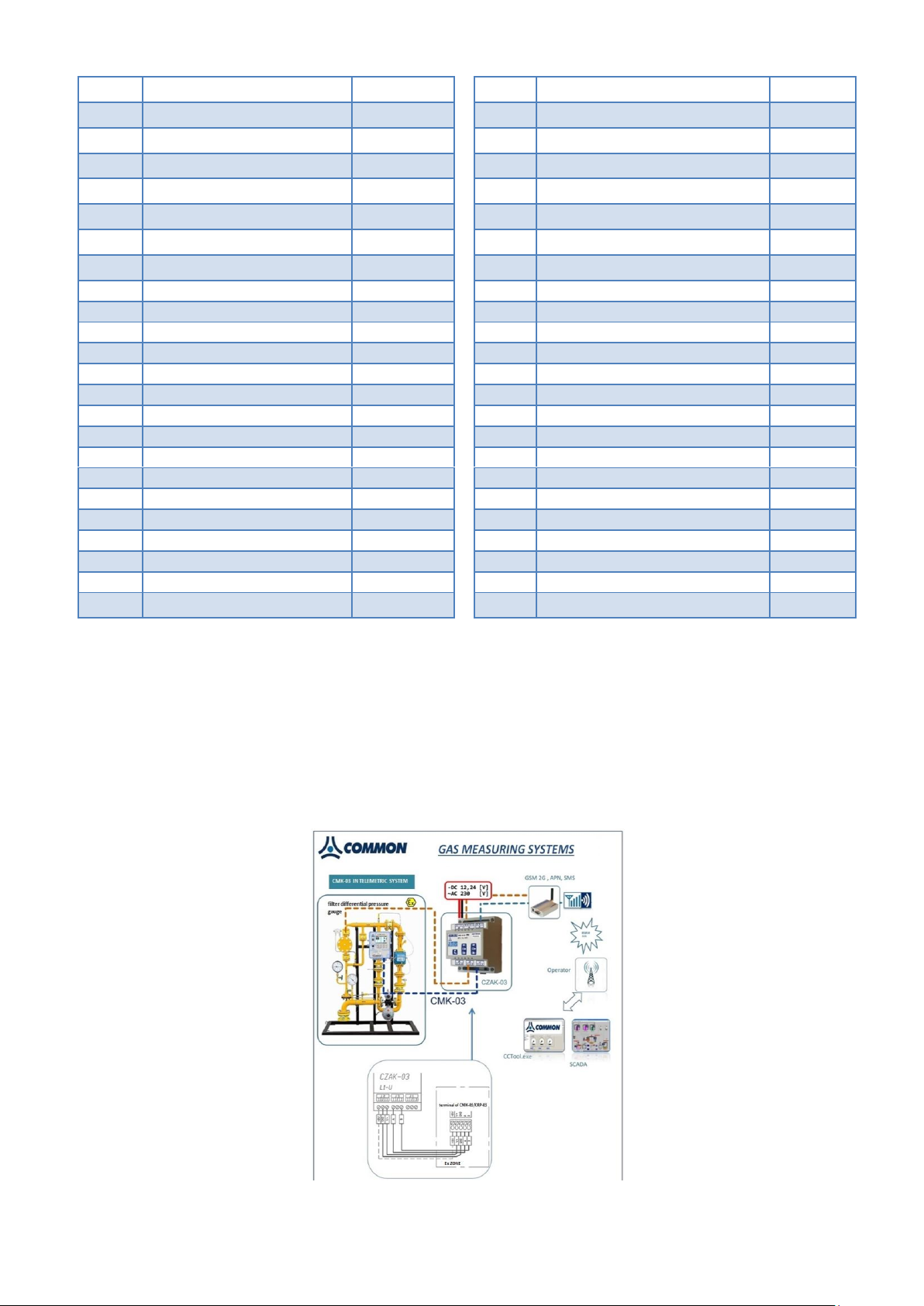
COMMON S.A. OPERATING INSTRUCTION CMK-03
9
p4 range exceeded
42
internal error (MID:8)
10
Przekr. zakr. t (MID:1)
43
Vb counter overfill (MID:128)
11
to range exceeded
44
Configuration change (MID:129)
12
CPC1 comm. Terror
45
Fill > 70% (MID:130)
13
CPC2 comm. error
46
Database full (MID:131)
14
CPC3 comm. Terror
47
Alarms confirmed (MID:132)
15
CPC4 comm. Terror
48
Battery < 10% (MID:133)
16
Signaling no. 1
49
Alg. Z range exceeded (MID:2)
17
Signaling no. 2
50
Calculation method error
18
Signaling no. 3
51
Open LFb ctrl. contact
19
Signaling no. 4
52
Qm limit exceeded
20
Signaling no. 5
53
Qb limit exceeded
21
Signaling no. 6
54
Qm meter range exceeded
22
Configuration lock
55
OPTO-GAZ active
23
External pwr. Supp
56
dVbsh1 limit exceeded
24
NAMUR pwr. supp.
57
dVbsh2 limit exceeded
25
Battery 1 disconnected
58
dVbsh3 limit exceeded
26
Battery 2 disconnected
59
eph1 limit exceeded
27
Check CALC
60
eph2 limit exceeded
28
Time change
61
Vm change
29
Aut. time change
62
Qmmin < Qm < QmStop
30
Value modification
63
eHF limit exceeded
31
String modification
32
Firmware upgraded (MID:134)
14.2 Reading and configuration in telemetric systems
The CMK-03 volume converter is equipped in three independent communication RS485 ports. They are executed
as intrinsically safe ports in the RS-GAZ2 standard. The configuration and remote reading in the telemetric systems is realized by using the Gaz-Modem 1/2/3 protocol.
The connection of communication ports (COM1, COM2, COM3), to the remote telemetric system is provided by
using a intrinsically safe power supply–converter e.g. CZAK-03 (see Table 2.1 Additional Accessories ). There is
also possible to use other power supply device with conformed parameters according to the Table 4.13.
Example of the telemetric systems is presented in Figure 14.1.
The connection diagram of the CZAK-03 clamps to the CMK-03 clamps is presented in Figure 14.2.
Figure 14.1 Example of telemetric system
83
Page 84
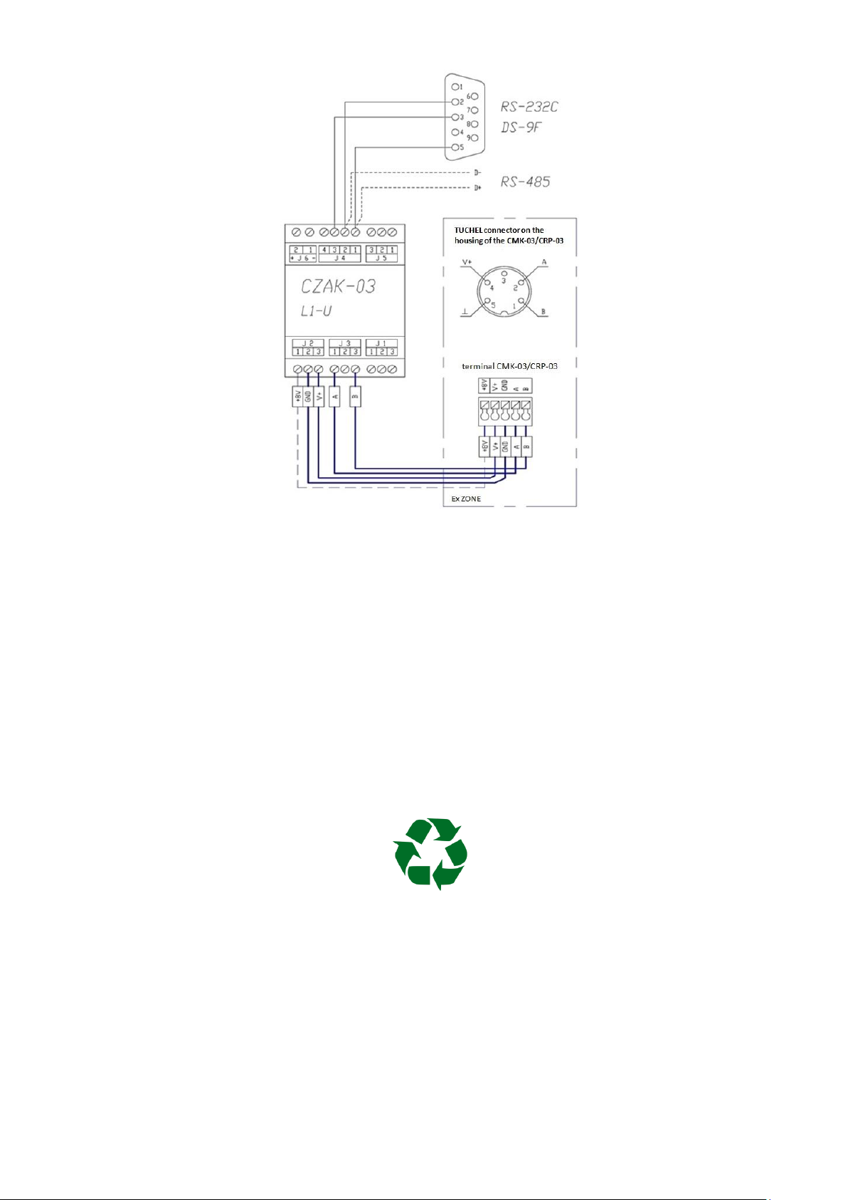
COMMON S.A. OPERATING INSTRUCTION CMK-03
Figure 14.2 Connection method of the CZAK-03 clamps into CMK-03 clamps
To provide the power supply to the volume converter and receive one transmission channel outside the Ex zone,
it is necessary to connect the cables of CZAK-03 clamps which are marked with labels V+, GND, A, B to the
identically marked clamps of the selected transmission port: COM1 (TUCHEL), COM2 or COM3.
If the CMK-03 will operate with NAMUR type reed transmitters, (the HF transmitter of gas meter or the proximi-
ty detectors) which are connected to the IN5 and/or IN6 input, it is necessary to connect the additionally cable
form CZAK-03 unit (except the external power supply V+, GND), which will provide the voltage +8,2V to NAMUR
circuits marked with +8V label.
15 Environmental protection.
15.1 Packaging waste
Packaging of delivered device should not be disposed as a municipal waste.
Packaging has been marked with a recycling symbol. According to the Packaging Regulations, the user is obliged
to ensure that individual elements of packaging are thrown into right containers for separate collection.
15.2 Disposal of used batteries and devices after their life-time.
There is not allowed to throw out as a municipal waste the items listed below:
used batteries
used accumulators after replacing
used devices after ending of their life-time
84
Page 85
COMMON S.A. OPERATING INSTRUCTION CMK-03
version
data
change description
101U
May 2015
first edition
102U
June 2016
second extended edition filled with technical descriptions and functionalities
The items are marked with the symbol:
The batteries (accumulators) and other parts of the devices contain hazardous and harmful substances. The
substances subject under the regulation of Waste Collection and should be prevent against the penetration to
natural environment.
If the company has not settled the procedure regarding to the electronically waste, the used batteries and/or
devices should be always delivered to proper collection point. The information about free of charge collection
points should be available on the website of municipal office.
16 History of changes in documentation
85
Page 86

COMMON S.A. OPERATING INSTRUCTION CMK-03
17 Notes
86
 Loading...