

Page 1
COMMON S.A.
ul. Aleksandrowska 67/93
91-205 Łódź, Poland
Phone no.: +48 42 2536600
Fax: +48 42 2536699
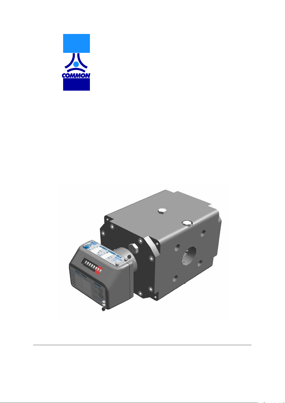
ROTARY
GAS METERS
series
CGR-01
OPERATION MANUAL
(Technical manual)
PLEASE READ THE OPERATION MANUAL BEFORE INSTALLING
CGR / IO12 / MID
July 2012
AND OPERATING THE GAS METER
Page 2

Table of Contents
Page
I. INTENDED USE AND CONDITIONS OF USE 2
II. DESIGN AND FUNCTION 7
III. READOUT DEVICE AND MEASUREMENT OUTPUTS 9
IV. LABELLING AND PROTECTION 14
V. PACKAGING, TRANSPORT AND STORAGE 16
VI. INSTALLATION AND OPERATION 19
VII. OPERATION MONITORING, MAINTENANCE, FAILURES,
REPAIRS 26
VIII. ADDITIONAL EQUIPMENT 28
IX. LIST OF STANDARDS AND TECHNICAL SPECIFICATIONS 31
CGR/IO12/MID 1
Page 3

I. INTENDED USE AND CONDITIONS OF USE
Mxx
Intended use
Rotary gas meters CGR-01 are electromechanical pressure devices designed to measure the
volume of gas flowing through a system. In standard embodiment, the gas meters may be
used at sites with probable occurrence of explosive atmospheres formed as mixtures of gases
classified as explosion groups IIA and IIB (and group IIC for the special purpose
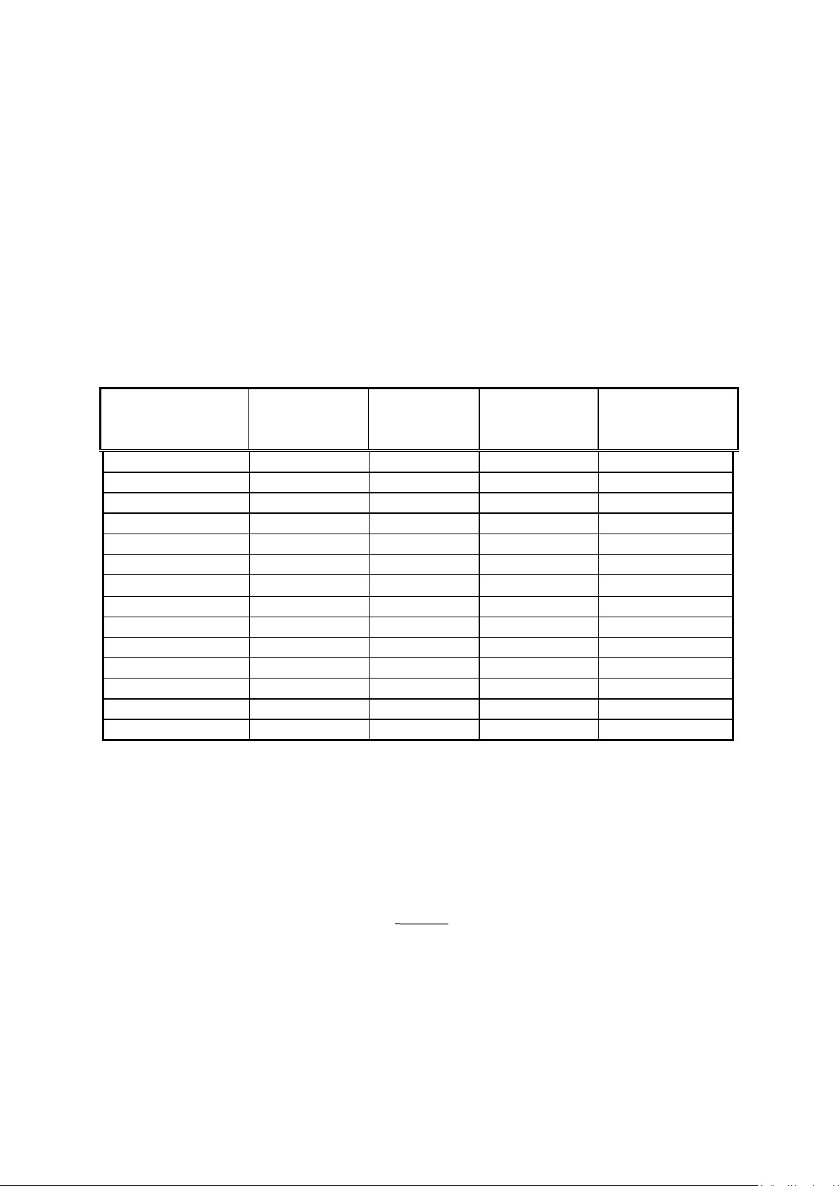
embodiment) with air. Table 1 lists the physical properties of the most common gases and gas
mixtures that may be measured with CGR-01 gas meters.
The rotary gas meters can be used both indoors in stabilized temperature conditions and
outdoors (open location); however, in the latter case, it is recommended that the gas meter is
shielded from direct exposure to atmospheric factors (metal containers, casings, roofs, shields
etc.) Ambient temperature range from –25°C to +70°C. System gas temperature range from
—20°C to +60°C. Storage temperature range from –30°C to +70°C. Maximum working
pressure p
= 1.6 MPa.
max
Conditions for use
1. Compliance with Directive 2004/22/WE (MID) :
- certificate PL – MI 002 – 1450CL0002
- CE marking 1450, Oil and Gas Institute
- ambient temperature range –25° C Ta + 70° C
- gas temperature range from –20° C to + 60° C
- storage temperature range from -30
- maximum working pressure p
= 1.6 MPa
max
o
C to + 70
o
C
- mechanical environment class M2
- electromagnetic environment class E2
- - metrological parameters Table 2.
- metrological accuracy class 1.0
- operational position HV,
- harmonized standards: PN-EN 12480:2005 (EN 12480:2002),
PN-EN 12480:2005/A1:2008 (EN 12480:2002/A1:2006),
2. Compliance with Directive 94/9/WE (ATEX) :
- certificate KDB 04ATEX034,
- CE marking 1453, Central Mining Institute, Experimental Mine
”Barbara”.
- operation conditions standard embodiment II 2G Ex ia IIB T5 Gb
special-purpose embodiment II 2G Ex ia IIC T5 Gb
- meter case index of protection IP66/IP67,
- harmonized standards: PN-EN 13463-1:2010 (EN 13463-1:2009),
PN-EN 60079-0:2009 (EN 60079-0:2009),
PN-EN 60079-11:2010 (EN 60079-11:2007).
3. Compliance with Directive 97/23/WE (PED) :
- certificate 37286/JN/001/04,
- CE marking 1433, Office of Technical Inspection
- compliance with technical specification WUDT/UC/2003.
CGR/IO12/MID 2
Page 4
- maximum calculated pressure for gas meter bodies:
Gas
or
gas mixture
Chemical
symbol
(formula)
Density
[kg/m3]
Relative
density
w
Gas meter
embodiment
argon
Ar
1.66
1.38
standard IIB
nitrogen
N2
1.16
0.97
standard IIB
butane
C4H10
2.53
2.1
standard IIB
carbon dioxide
CO2
1.84
1.53
standard IIB
ethane
C2H6
1.27
1.06
standard IIB
ethylene
C2H4
1.17
0.98
standard IIB
natural gas
CH4
ca. 0.75
ca. 0.63
standard IIB
helium
He
0.17
0.14
standard IIB
methane
CH4
0.67
0.55
standard IIB
propane
C3H8
1.87
1.56
standard IIB
carbon monoxide
CO
1.16
0.97
standard IIB
acetylene
C2H
2
1.09
0.91
special IIC
hydrogen
H2
0.084
0.07
special IIC
air – 1.20
1
standard IIB
·Wpd·p
p p p
p
rz a
a
w
connection PN16 PS = 16 bar,
connection PN20 (ANSI150) PS = 20 bar,
connection PN25 (only cast iron bodies) PS = 25 bar.
- ambient temperature –25° C to + 70° C
4. Compliance with Directive 2004/108/WE (EMC) :
- requirements met by the use of LF and HF pulse emitters (NAMUR)
compliant with the following harmonized standards:
PN-EN 60947-5-2:2011 (EN 60947-5-2:2007),
PN-EN 60947-5-6:2002 (EN 60947-5-6:2000).
Table 1. Physical properties of the most common gases and gas mixtures that may be
measured with CGR-01 gas meters. Densities under pressure of 101.325 kPa at
20o C
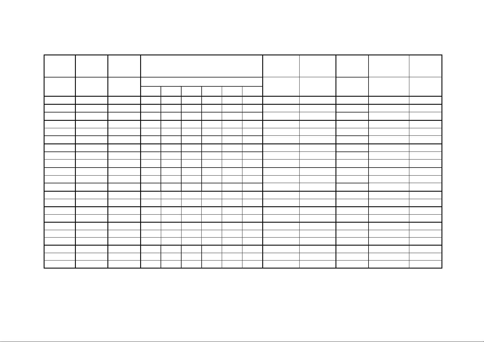
Basic metrological parameters of CGR-01 rotary gas meters are listed in Tables 2a and 2b.
The table should not be taken as current sales offer; relevant information may be obtained at
Common S.A. .
The gas meter causes a gas pressure drop in the system. The values of the gas pressure drops
as determined at Q
(for atmospheric air conditions with density 0 = 1.2 kg/m3) for all
max
CGR gas meter embodiments may be found in Table 2.
In actual conditions, pressure loss pr [Pa] is calculated according to the formula:
where:
p
p – gauge gas pressure upstream the gas meter [kPa],
Wpd – Pressure drop ratio determined from Fig. 1
p – pressure drop at Q
= / 0 – relative gas density (compared to air density) as in Table 1,
w
– atmospheric pressure (pa 101 [kPa] ),
a
determined from Table 2 [Pa].
max
CGR/IO12/MID 3
Page 5
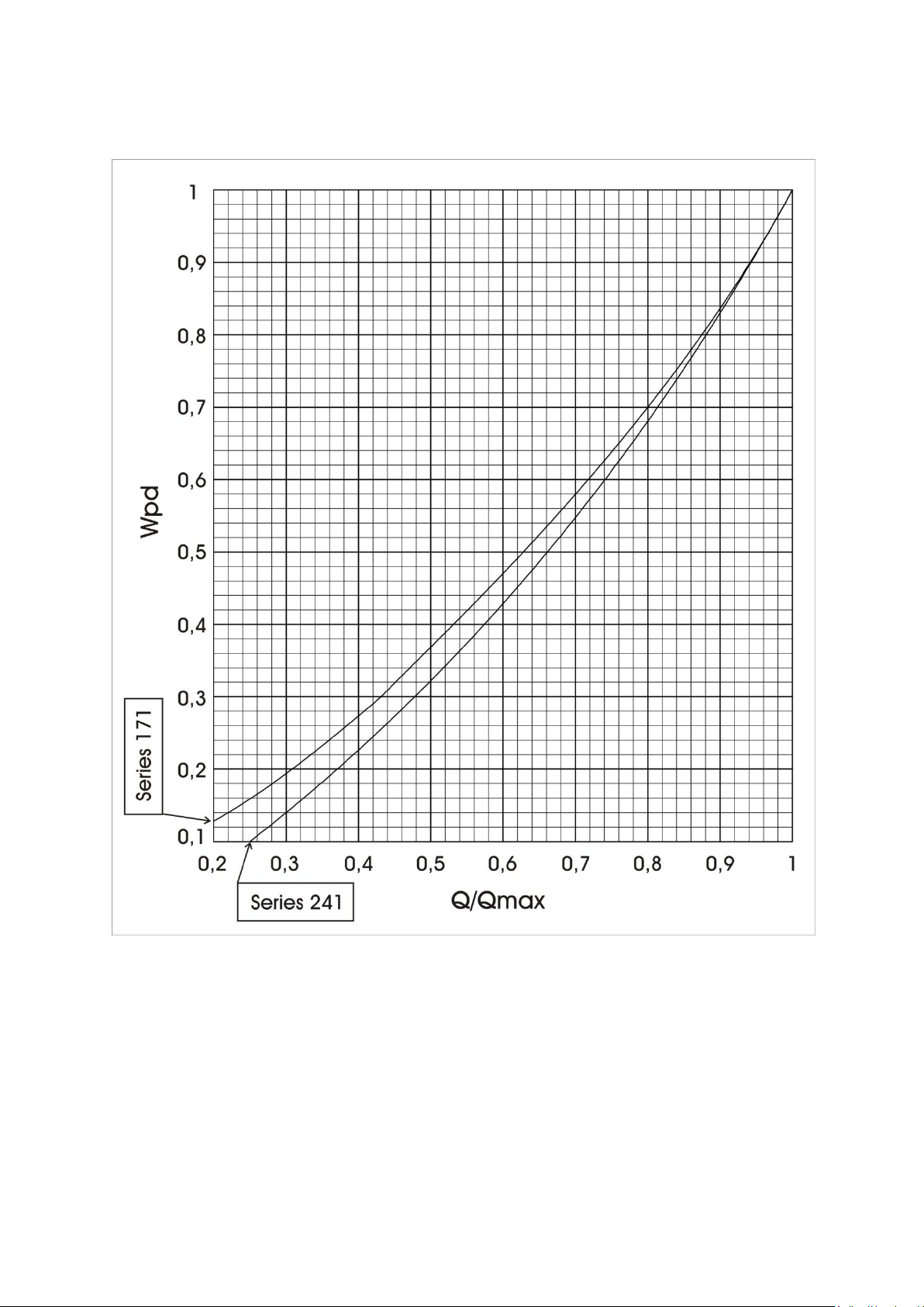
Fig. 1. The pressure drop ratio as a function of the relative flow Q/Q
CGR/IO12/MID 4
max
.
Page 6
DN
nominal
diameter
G
Gas meter
size
Q
max
Maximum
flow
Q
min
minimum flow in [m3/h ]
LF
emitter constant
HF
emitter constant
(approximate)
V
cyclic
volume
∆p
loss of pressure
at Q
max
Gas meter
series
[mm]
[m3/h]
scale:
[pulses/m3]
[pulses/m3]
[dm3]
[Pa]
[–]
1:50
1:65
1:100
1:160
1:200
1:250
40/50
G10p
16
0.3
0.25
0.16 – –
–
10
15459
0.23
110/85
"171"
40/50
G16p
25
0.5
0.4
0.25
0.16 – –
10
15459
0.23
185/140
"171"
40/50
G16w
25
0.5
0.4
0.25
0.16 – –
10
11470
0.31
105/80
"171"
40/50
G25s
40
0.8
0.65
0.4
0.25
0.2
0.16
10
15459
0.23
375/280
"171"
40/50
G25p
40
0.8
0.65
0.4
0.25
0.2
0.16
10
11470
0.31
240/180
"171"
40/50
G25w
40
0.8
0.65
0.4
0.25 – –
10
7111
0.50
110/80
"171"
40/50
G40s
65
1.3
1.0
0.65
0.4
0.3
0.25
10
11470
0.31
480/360
"171"
40/50
G40p
65
1.3
1.0
0.65
0.4
0.3
0.25
10
7111
0.50
280/210
"171"
40/50
G40w
65
1.3
1.0
0.65
0.4 – –
10
4390
0.81
195/150
"171"
50/80
G65s
100
2.0
1.6
1.0
0.65
0.5
0.4
10
7111
0.50
420/320
"171"
50/80
G65p
100
2.0
1.6
1.0
0.65
0.5
0.4
10
4390
0.81
325/290
"171"
50/80
G65w
100
2.0
1.6
1.0
0.65 – –
10
2867
1.24
245/200
"171"
50/80
G100s
160
3.2
2.5
1.6
1.0
0.8
0.65
1
4390
0.81
570/430
"171"
50/80
G100p
160
3.2
2.5
1.6
1.0
0.8
0.65
1
2867
1.24
505/395
"171"
80/100
G100p
160
3.2
2.5
1.6
1.0
0.8
0.65
1
1654
1.29
220/160
"241"
80/100
G100w
160
3.2
2.5
1.6
1.0 – –
1
1067
2.00
180/135
"241"
80/100
G160s
250
5.0
4.0
2.5
1.6
1.3
1.0
1
1654
1.29
530/400
"241"
80/100
G160p
250
5.0
4.0
2.5
1.6
1.3
1.0
1
1067
2.00
370/280
"241"
80/100
G160w
250
5.0
4.0
2.5
1.6 – –
1
639
3.34
270/210
"241"
100
G250s
400
8.0
6.5
4.0
2.5
2.0
1.6
1
1067
2.00
660
"241"
100
G250p
400
8.0
6.5
4.0
2.5
2.0
1.6
1
639
3.34
510
"241"
100
G400s*
650
13
10
6.5
4.0
3.2
2.5
1
639
3.34
1380
"241"
Table 2a. Basic metrological parameters of CGR-01 gas meters in aluminium bodies.
Gas meter size p – basic version;
w – low-speed version (larger overall dimensions, reduced pressure loss and noise level),
CGR/IO12 5
s – high-speed version (smaller overall dimensions, increased pressure loss and noise level),
* – MID certificate does not apply to this version.
Page 7
DN
nominal
diameter
G
Gas meter
size
Q
max
Maximum
flow
Q
min
minimum flow in [m3/h ]
LF
emitter constant
HF
emitter constant
(approximate)
V
cyclic volume
∆p
loss of pressure at
Q
max
Gas meter
series
[mm]
[m3/h]
scale
[pulses/m3]
[pulses/m3]
[dm3]
[Pa]
[–]
1:50
AM
1:65
1:100
1:160
1:200
1:250
40/50
G10w
16
0.3
0.25 – – – –
10
7111
0.50
33/17
"171"
40/50
G16w
25
0.5
0.4
0.25 – – – 10
7111
0.50
45/35
"171"
40/50
G25w
40
0.8
0.65
0.4
0.25 – –
10
7111
0.50
110/80
"171"
40/50
G40p
65
1.3
1.0
0.65
0.4
0.3
0.25
10
7111
0.50
280/210
"171"
40/50
G40w
65
1.3
1.0
0.65
0.4 – –
10
4390
0.81
195/150
"171"
50/80
G65s
100
2.0
1.6
1.0
0.65
0.5
0.4
10
7111
0.50
420/320
"171"
50/80
G65p
100
2.0
1.6
1.0
0.65
0.5
0.4
10
4390
0.81
325/290
"171"
50/80
G65w
100
2.0
1.6
1.0
0.65 – –
10
2867
1.24
245/200
"171"
50/80
G100s
160
3.2
2.5
1.6
1.0
0.8
0.65 1 4390
0.81
570/430
"171"
50/80
G100p
160
3.2
2.5
1.6
1.0
0.8
0.65 1 2867
1.24
505/395
"171"
80/100
G100w
160
3.2
2.5
1.6
1.0 – – 1 1067
2.00
180/135
"241"
80/100
G160p
250
5.0
4.0
2.5
1.6
1.3
1.0 1 1067
2.00
370/280
"241"
80/100
G160w
250
5.0
4.0
2.5
1.6 – – 1 639
3.34
270/210
"241"
100
G250s
400
8.0
6.5
4.0
2.5
2.0
1.6 1 1067
2.00
660
"241"
100
G250p
400
8.0
6.5
4.0
2.5
2.0
1.6 1 639
3.34
510
"241"
100
G400s*
650
13
10
6.5
4.0
3.2
2.5
1
639
3.34
1380
"241"
Table 2b. Basic metrological parameters of CGR-01 gas meters in cast iron bodies.
Gas meter size p – basic version;
w – low-speed version (larger overall dimensions, reduced pressure loss and noise level),
s – high-speed version (smaller overall dimensions, increased pressure loss and noise level),
* – MID certificate does not apply to this version.
CGR/IO12/MID 6
Page 8
II. DESIGN AND FUNCTION
The rotary gas meter is a volumetric rotary machine based on the principle of proportionality
of the speed of rotation of rotors to the actual volume of gas flowing through the gas meter at
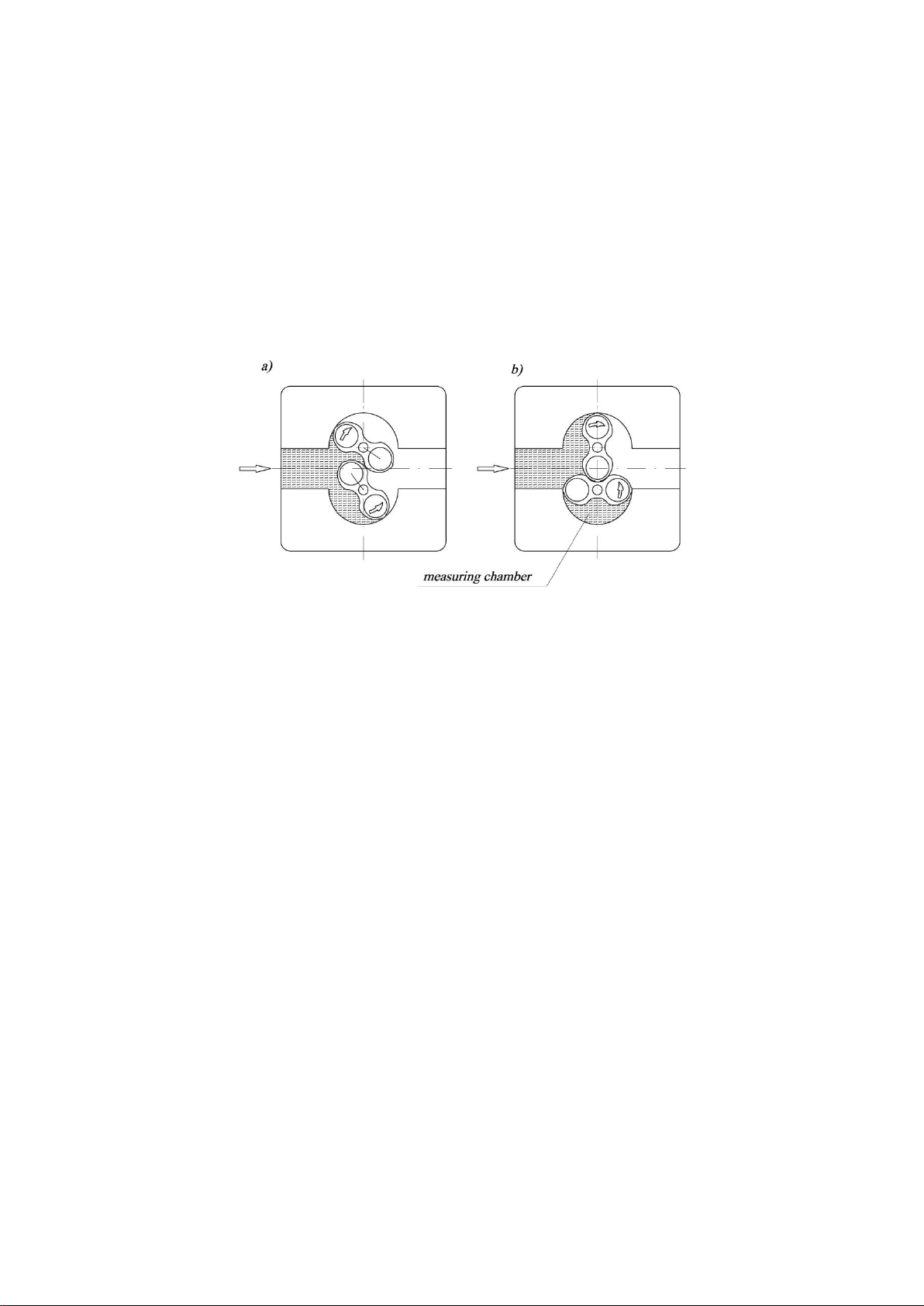
particular pressure and temperature conditions. The gas flowing into the gas meter (Fig. 2)
fills the measurement chamber and the inlet overpressure causes rotation of rotors and
transport of a portion of gas to the gas meter outlet. The rotational motion of rotors is
transmitted to the counter by means of gears and magnetic clutch. The counter mechanism
totals up the volume flowing through the device, and a revolving counter indicates the total
volume.
Fig. 2. Operation of the CGR-01 rotary gas meter.
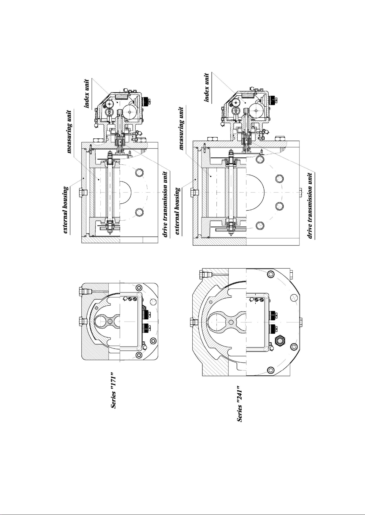
The rotary gas meter (Fig. 3) is built of the following basic elements:
Main body. The main body assembly consists of the main body and the front and back
covers. The covers are bolted to the body and secured with seals. The main body is complete
with sockets for the measurement of gas pressure and temperature and two flat face
connections with threaded holes to install the gas meter in the pipeline. The front cover
includes a gas-tight partition to separate the gas chamber from the environment as well as the
oil filler plug and oil level inspection window.
The measurement assembly. The measurement assembly is secured between the main body
covers using elastic sealing inserts. The assembly consists of the measurement chamber with
rotating rotors and two side chambers separated by internal partitions. The rotors are installed
in these covers using roller bearings. Both side chambers contain a reserve supply of oil for
lubrication of bearings and gears of the measurement system. Lubrication is achieved by
means of oil spray generated by blades installed on rotor shafts.
Drive transmission assembly. The drive transmission assembly is installed in the front cover
and transmits the rotary motion of the rotors from the measurement assembly to the counter
through a gas-tight partition. The assembly consists of a cog gear and a magnetic clutch. The
driven part of the clutch may be complete with an inducer for the high frequency emitter.
The counter assembly. The counter assembly further reduces the rotational speed (by means
of a worm gear and cylindrical gears) to drive the mechanical counter and the elements that
induce the low frequency electric signal emitters. The assembly is also complete with sockets
for transmitting the low and high frequency electric signals outside the gas meter.
CGR/IO12 7
Page 9
CGR/IO12/MID 8
Page 10

Fig. 3. Cross-section of the rotary gas meter CGR-01
CGR/IO12/MID 9
Page 11
III. READOUT DEVICE AND MEASUREMENT OUTPUTS
The gas meter CGR-01 is equipped with a readout device in the form of a mechanical counter
and electric signal outputs, a pressure measurement output and temperature measurement
output (optional). The outlets allow to monitor the gas meter operation and to connect the
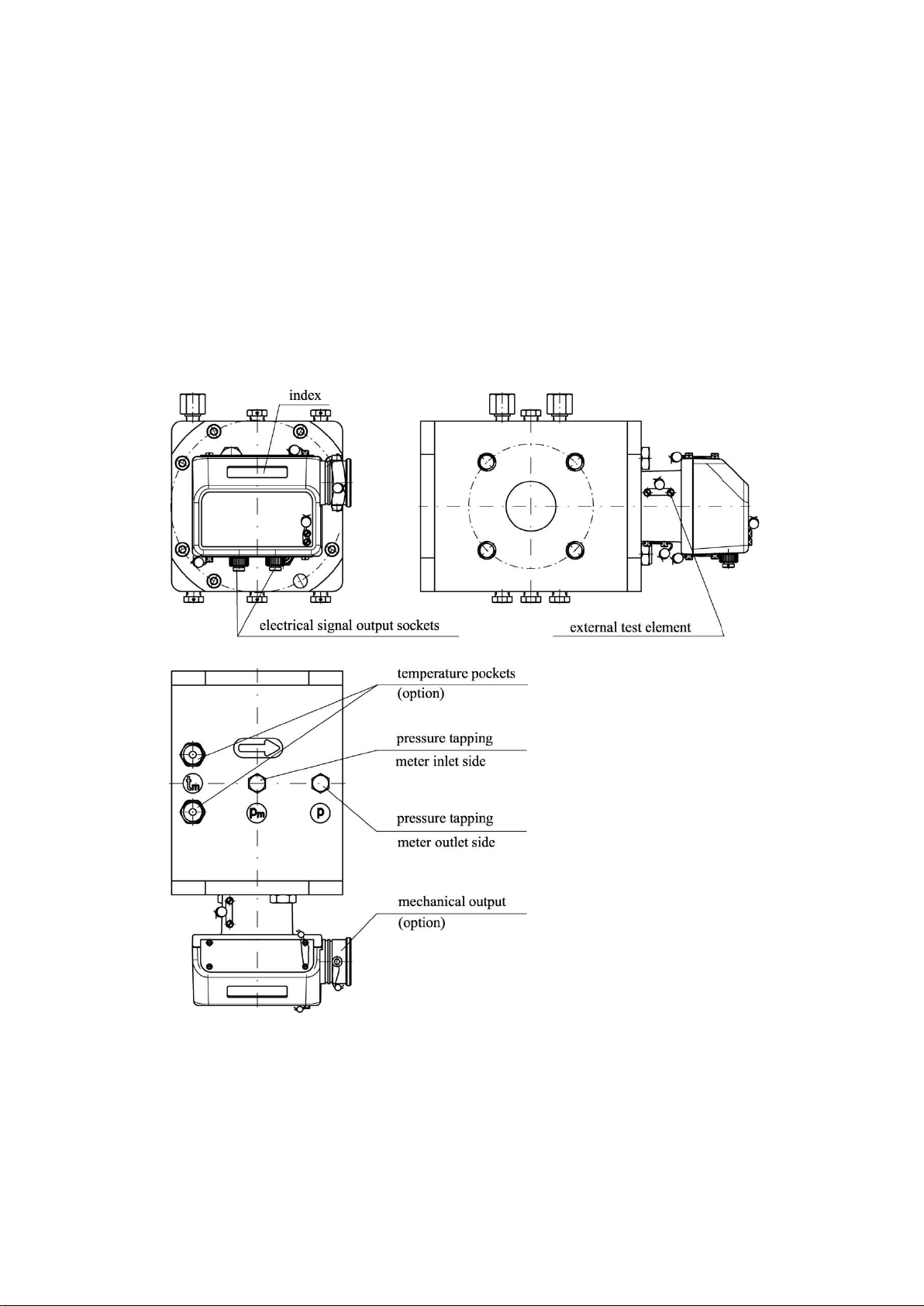
external equipment. Fig. 4 shows the location of the measurement outlets on the gas meter.
The mechanical counter is located inside the counter assembly and visible through a
polycarbonate inspection window. The counter allows direct readout of the actual volume of
gas that has flown through the gas meter under particular pressure and temperature conditions.
The counter assembly may be rotated around the horizontal axis of the gas meter in a range of
ca. 350o, allowing for convenient readout of the counter from virtually all directions.
Fig. 4. Location of measurement outlets of a CGR-01 gas meter.
Electric signal outlets. There are two possible types of electric signal outlets: low frequency
(LF) outlets and high frequency (HF) outlets. The counter may be equipped with the
maximum of two sockets and six electric pulse emitters.
- Two low frequency reed contact emitters (LFK),
- two inductive low frequency emitters (LFI),
CGR/IO12/MID 10
Page 12
conta
ct
polarity
LFK 1
LFK 2
AFK
LFI 1
LFI 2
HF 1
HF 2
1 S O
4 + S O
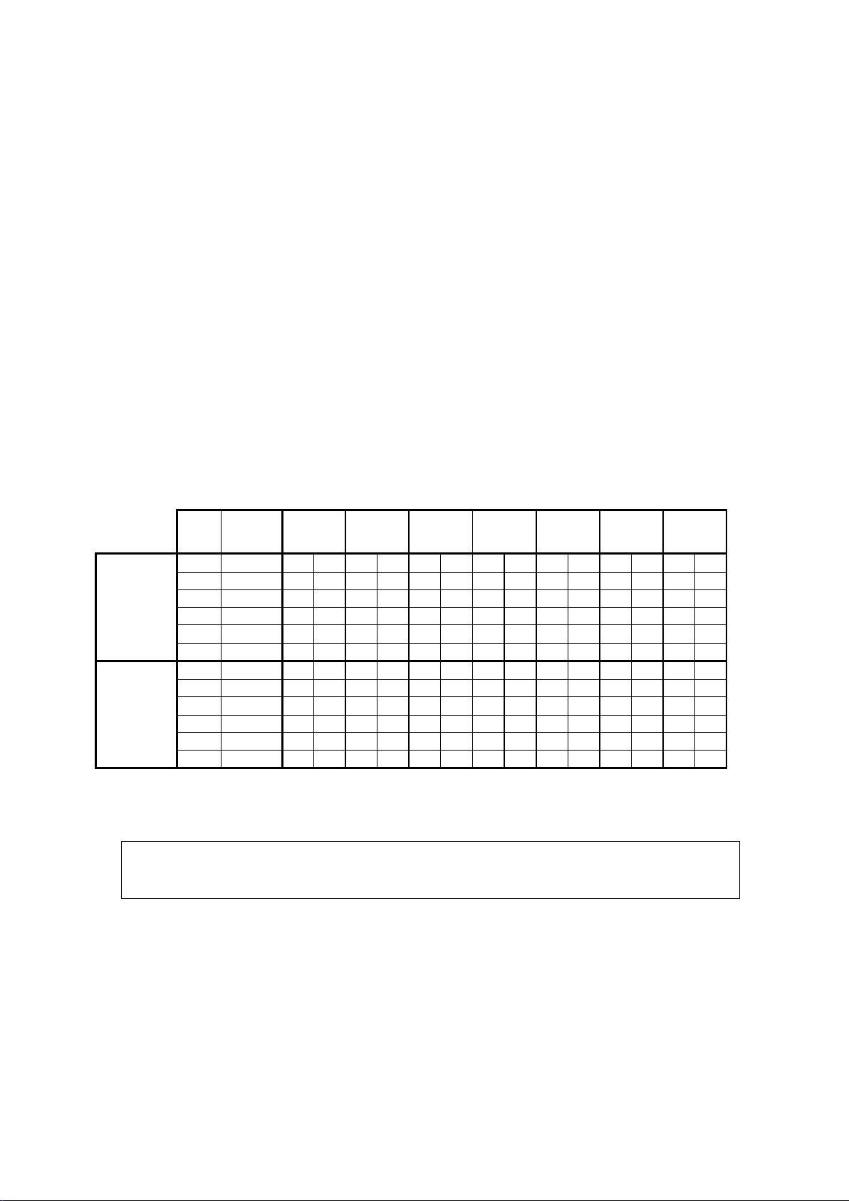
Socket 1
2 O P P O O
5 + O P P O O
3 O P
6 + O P
1 P O
4 + P O
Socket 2
2 O O P O
5 + O O P O
3 O P
6 + O P
S – standard connections
P – preferred connections
O – optional connections
Standard embodiment of the CGR-01 gas meter features only one
low frequency reed relay emitter LFK 1.
- two inductive high frequency emitters (HF),
and with a control circuit featuring a normally closed reed relay switch AFK or, alternatively,
any other emitter.
The reed relay emitters LFK are designed to work with a battery-powered or grid/batterypowered data logger and volume converter located in the vicinity of the gas meter (up to ca. 2
m). The induction emitters, both of the LFI and the HF type, may emit electric current signals
over significantly longer distances (up to ca. 200 m, depending on conditions). Due to high
power consumption, they are designed to work only with grid-powered volume converters.
Gas volumes corresponding to individual pulses of the LF emitter are presented in Table 2.
The number of HF pulses per one square meter of gas is determined individually for each gas
meter and listed on the type plate. The approximate value of the HF emitter constant is given
in Table 2. The HF outlet is particularly useful for tracking changes in the flux of the gas
flowing through the gas meter.
All emitters located in the gas meter counter assembly are connected to Amphenol-Tuchel
C091 31N006 100 2 sockets located in the back wall of the counter case. Cords connected to
sockets should be equipped with Amphenol-Tuchel C091 31H006 100 2 plugs. AmphenolTuchel connections in CGR gas meters are in the IP67 protection class. Table 3 presents
potential connections of emitters to individual electric signal output sockets.
Table 3. Potential connections of gas meter emitters to electrical output sockets.
One of the inductive emitters installed in the counter may act as a control element in the
CGR-01 gas meter. If the counter is not equipped with a HF emitter, an external control
element may be connected to the gas meter for testing purposes (see section VII). Inductive
HF emitter type Bi1-EG05-Y1 by Hans Turck GmbH should be used as the external control
element. The type plate of the gas meter includes the value of the constant for emitters HF1
and HF2; this value is also valid for the external control element emitter. After disconnecting
the control element, the socket is tightly plugged and sealed (Fig. 9).
CGR/IO12/MID 11
Page 13
HF
LFI
LFK
Ui = 20 V DC
Ui = 20 V DC
Ui = 15.5 V DC
Ii = 60 mA
Ii = 60 mA
Ii = 52 mA
Pi = 200 mW
Pi = 130 mW
Pi = 169 mW
Li = 150 μH
Li = 350 μH
Li ≈ 0
Ci = 150 nF
Ci = 250 nF
Ci ≈ 0
In line with the conditions for use, the CGR-01 gas meters should be equipped with emitters
allowing for at least II 2G Ex ib IIC T5 Gb protection. This condition is satisfied for
instance by the following emitters used in the counter:
- HF type Bi1-EG05-Y1
- LFI type Si5-K09-Y1-LF
(1)
by Hans Turck GmbH; II 1G Ex ia IIC T6.
(1)
by Hans Turck GmbH; II 1G Ex ia IIC T6.
- LFK type CLFK-02 by Common S.A. II 2G Ex ia IIC T6.
(1) – required linear characteristics of the emitter power circuit.
Acceptable intrinsic safety parameters
Intrinsic safety parameters of the emitters installed in the gas meter are listed on the type
plate.
Nominal operating parameters of the emitters:
reed relay emitter CLFK-02:
closed switch resistance R
= 100 ÷ 2 k ,
z
open switch resistance Ro > 100 M ,
max. switching frequency f
inductive emitters Si5-K09-Y1-LF Bi1-EG05-Y1
max. switching frequency f
= 2 Hz, fp = 0.5 kHz.
p
= 2 Hz .
p
The remaining nominal operating parameters of the emitters used in the gas meters are in line
with the requirements of the PN-EN 60947-5-6:2002 standard.
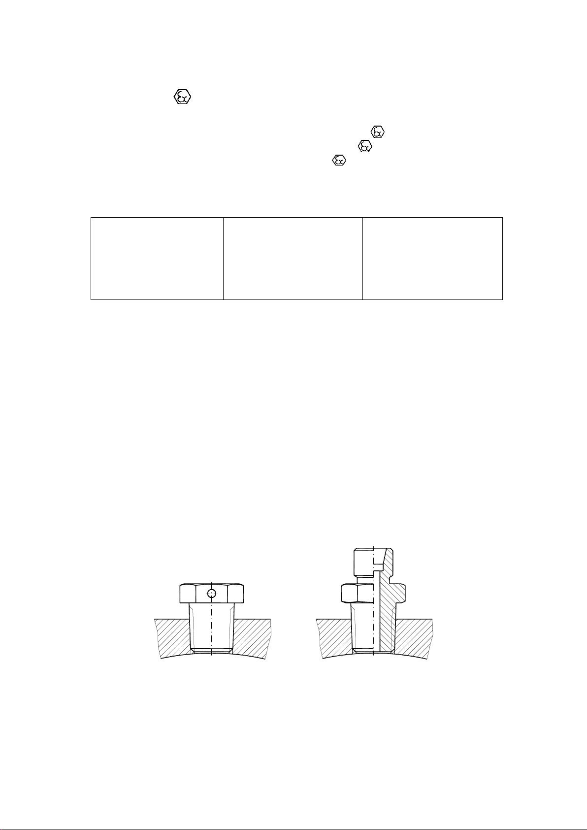
Pressure measurement outlet.
Pressure measurement outlets (pulse openings) are located at both sides of the main body
(Fig. 4). Openings are complete with ¼ NPT threaded slots (Fig. 5).
a.) b.)
The outlets are used to connect pressure transducers, either directly to the socket (Fig. 5b) or
via three-way valves. Outlets that are not in use are blinded with plugs (Fig. 5a). Both plugs
and sockets may be protected by installation seals.
CGR/IO12/MID 12
Fig. 5. ¼ NPT pressure measurement slot
Page 14
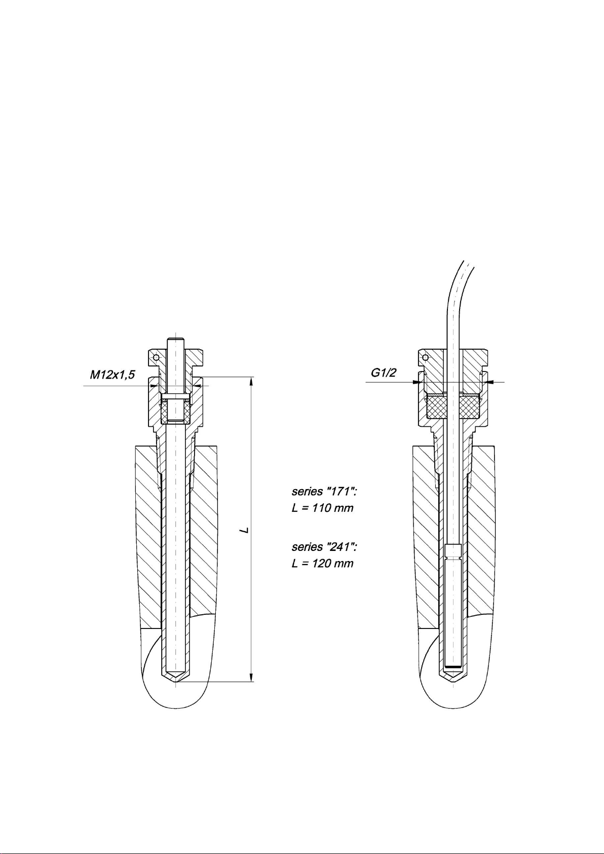
Temperature measurement outlet.
The turbine gas meter CGR-01 allows temperature measurements only when delivered as a
special order version; temperature measurements are not available in the standard version.
Temperature measurement outlets are located at both sides of the main body (Fig. 4). The
body openings are complete with temperature pockets (Fig. 6) with the length of L=110 mm
for the bodies of the “171” series and L=120 mm for the bodies of the “241” series. The
temperature pockets feature G ½” thread sockets (M12 x 1.5 in special embodiments).
Electric thermometer tips or temperature transducers are immersed in silicone oil in the
thermometric ferrules (Fig. 6b). Temperature pockets not in use (Fig. 6a) are blinded with
plugs. Outlets that are not in use are blinded with ¼ NPT plugs (Fig. 5a).
a) A temperature pocket b) Temperature pocket with a thermometer
Fig. 6 Temperature pockets
CGR/IO12/MID 13
Page 15
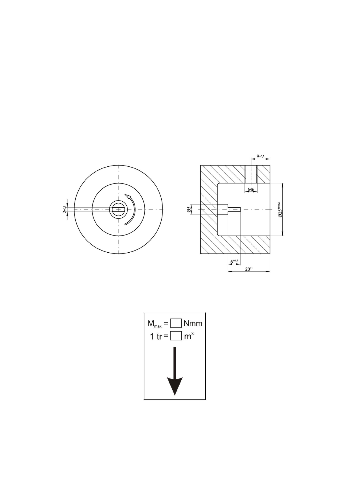
Mechanical counter outlet (option)
The gas meter may be optionally equipped with a mechanical outlet. The mechanical outlet
may be used to drive external, removable devices connected to the gas meter counter. A
paddled tip of the counter shaft is located on the right side of the counter and covered by a
protective cap. The rotational speed of the shaft is identical to the speed of the fastest counter
barrel. The shaft rotates in counter-clockwise direction; the direction is marked on the plate
(Fig. 7b) fixed at the mechanical outlet cover. The values of the maximum acceptable
allowable momentum of the mechanical outlet shaft tip M
corresponding to one complete turn of the drive shaft, 1 tr = …… [m
= …… [Nmm] and the constant
max
3
] are also given on the
plate.
Fig. 7a Mechanical outlet drive shaft
Fig. 7b Mechanical outlet type plate
CGR/IO12/MID 14
Page 16
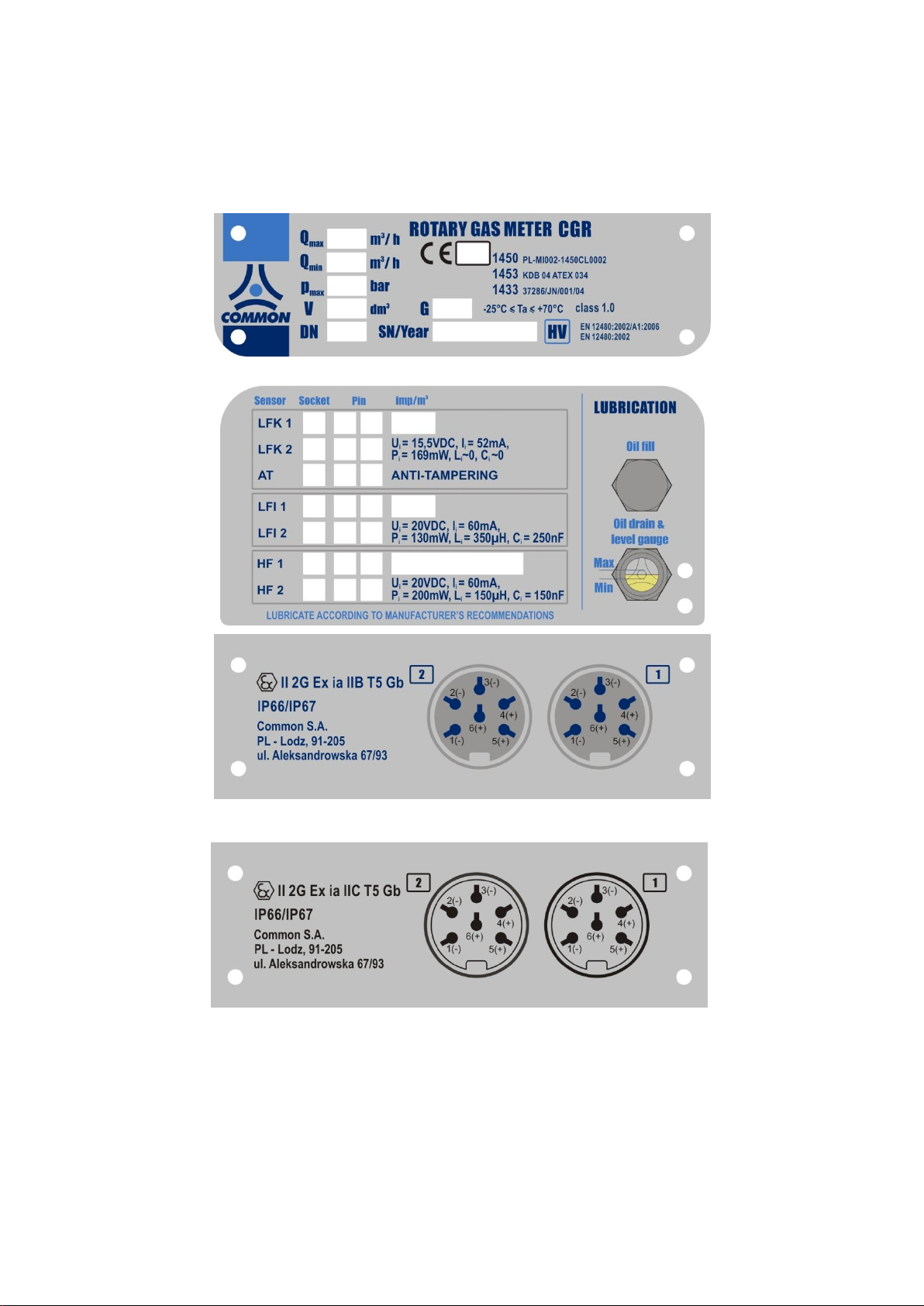
IV. LABELLING AND PROTECTION
Information on the basic technical parameters of the gas meter along with the serial number
and manufacture year is listed on rating plates (Figs. 8a and 8b) bolted to the counter casing.
Fig. 8a. Type plates – standard version IIA and IIB
Fig. 8b. Type plates – special version IIC
The top of the gas meter body features signs informing about the direction of gas flow and the
locations of pressure and temperature measurement outlets (Fig. 4).
Following verification by the authorized manufacturer laboratory, each gas meter is protected
with seals placed in locations shown in Fig. 9. Seal P1 features the initial verification or
secondary verification stamp (Fig. 10) while seals P2, P3, P4, P5, P6, P7, P8 feature
CGR/IO12/MID 15
Page 17
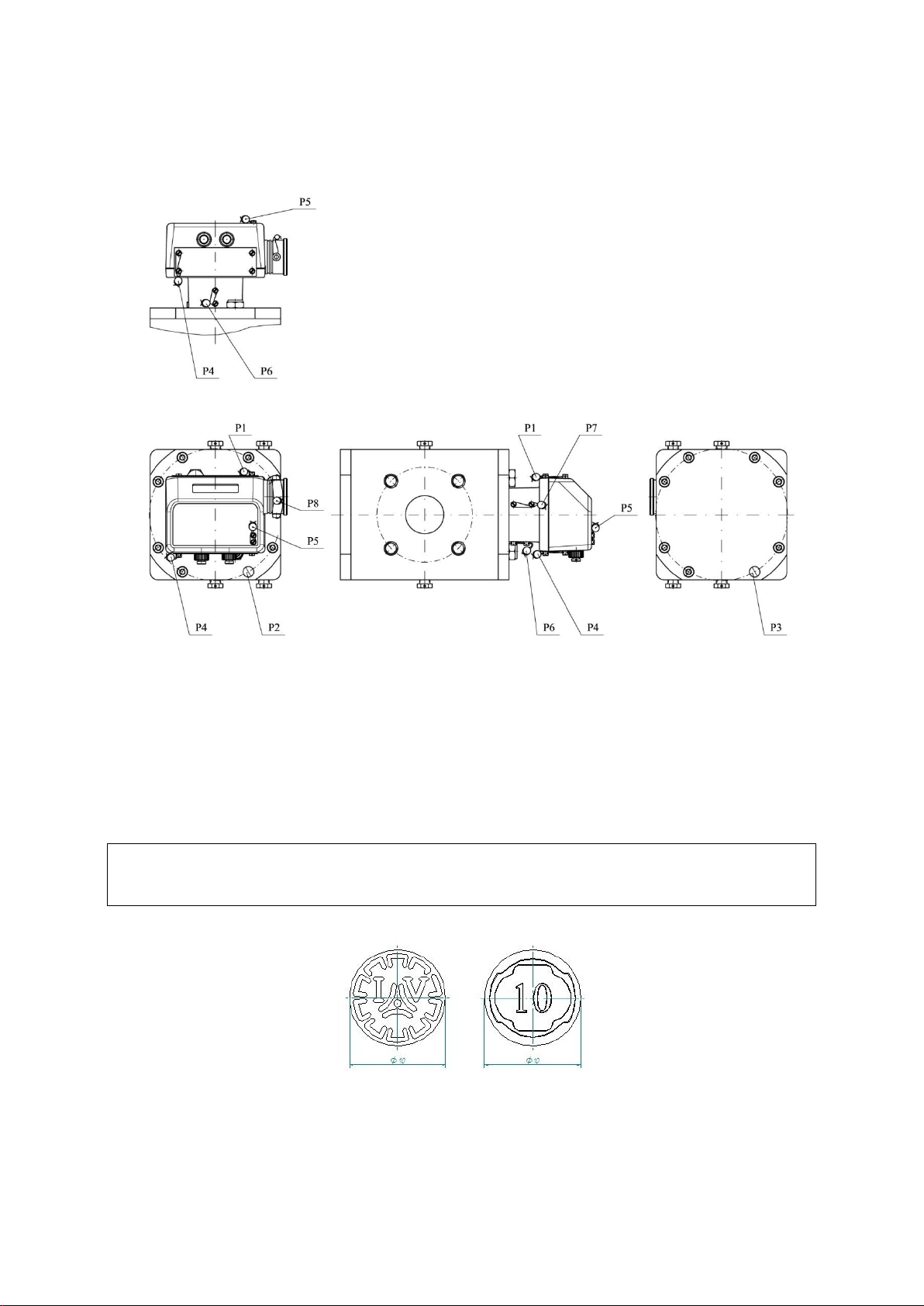
Retaining the verification stamp seal is required for the gas meter to be considered a
legal measurement device.
protection stamps. By request of the customer, the gas meter may be delivered along with the
verification certificate that documents its verification.
Fig. 9. Locations of seals on CGR gas makers
The initial verification period depends on metrological regulations in the country of
installation. Before the end of the verification period, the gas meter should be submitted for
secondary verification at an authorized laboratory (one should also provide for the waiting
time before the actual legal approval date)
Common S.A. offers secondary verification at the manufacturer's laboratory, allowing for
adjustments or repairs of the gas meters, if required.
Fig. 10 Initial verification stamp
CGR/IO12/MID 16
Page 18

The rotary gas meter is a high precision measurement device
and should be handled with appropriate caution.
V. PACKAGING, TRANSPORT AND STORAGE
The gas meter is supplied in factory-made packaging which provides appropriate protection
during transport and storage (Figs 11a and 11b). The packaging consists of reinforced
cardboard box and profiled cardboard inserts. Appropriate information regarding the contents
and restrictions regarding gas meter loading/unloading and transport is printed on the
packaging. Side walls of the box feature handle holes for transporting the gas meter. Gas
meters submitted for repair or renewed legal approval should be sent in factory-made
packaging or other packaging providing at least equal protection during transport.
Every rotary gas meter produced by Common S.A. is supplied with the following:
- a 6-pin Amphenol-Tuchel C091 31H006 100 2 plug to be used for connecting a
converter or data logger to the low frequency electric signal outlet;
- a bottle of oil for gas meter lubrication;
- a set of elements for fixing the gas meter in the installation: hexagonal flat end
M16x70 set screws compliant with the PN-EN ISO 4026:2004 standard, washers
and nuts;
- the technical manual.
Following principles should be observed during transport and storage of the gas meters:
1. Gas meters should not be thrown, turned over or subjected to strong impacts (e.g. during
fast transport using carts without springs).
2. One must not lift or carry the gas meter by holding the counter assembly case.
3. Factory-placed covers or other shields of gas meter orifices should not be removed until
directly before installation.
4. The storage site should protect the gas meter from atmospheric precipitation and moisture.
5. Care should be taken of the seals placed on the gas meter. Damage of seals may lead to
warranty voidance and legal consequences as regards the clearance of accounts
between the gas supplier and the customer.
6. It is not required for the gas meter to be primed with oil during warehouse storage.
CGR/IO12/MID 17
Page 19
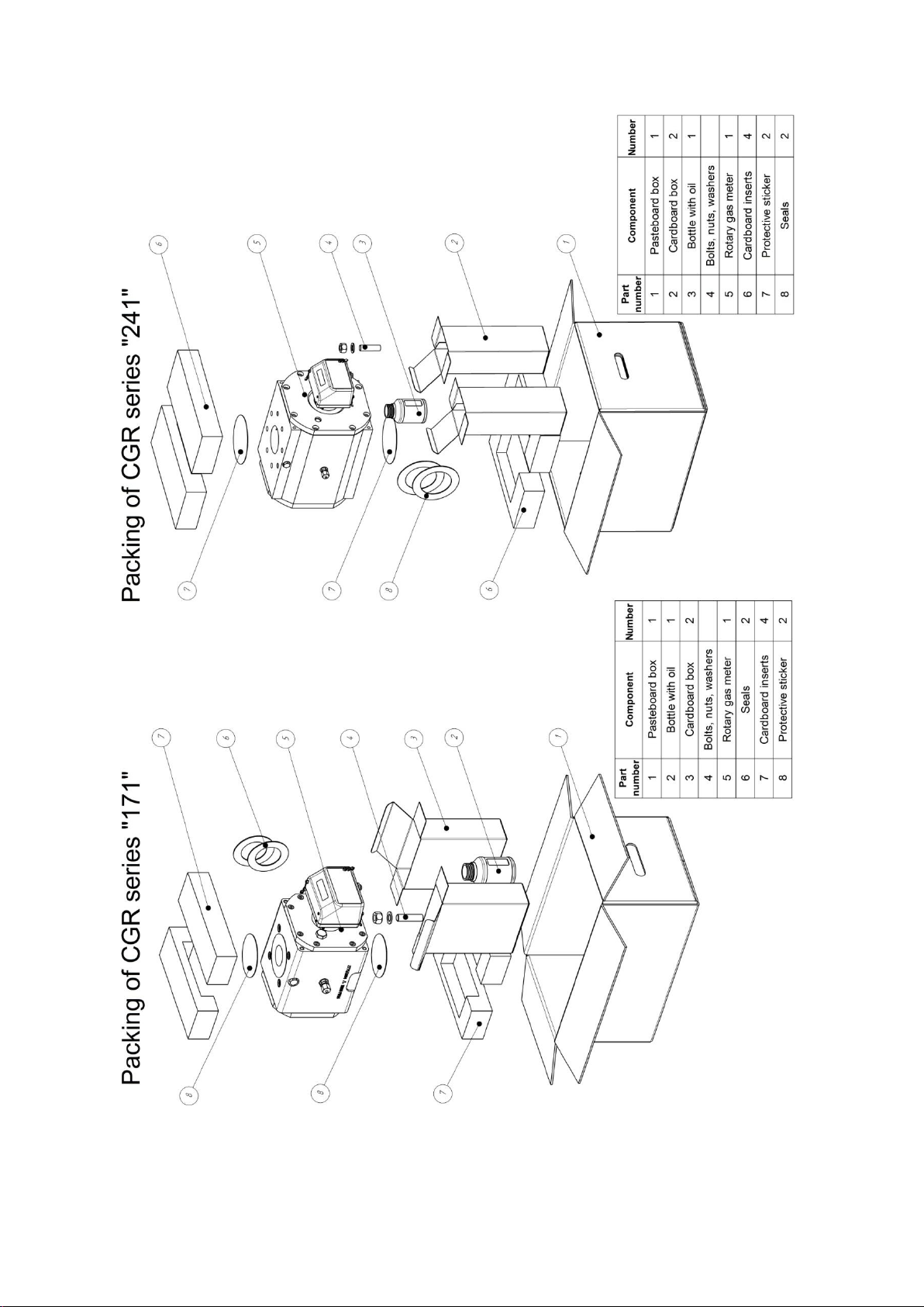
Fig. 11a & 11b. Packaging of the CGR-01 gas meters series “171” & “241”
CGR/IO12/MID 18
Page 20
Maximum load of the gas meter, Q
max
, may be exceeded
by not more than 25% for not longer than 30 minutes.
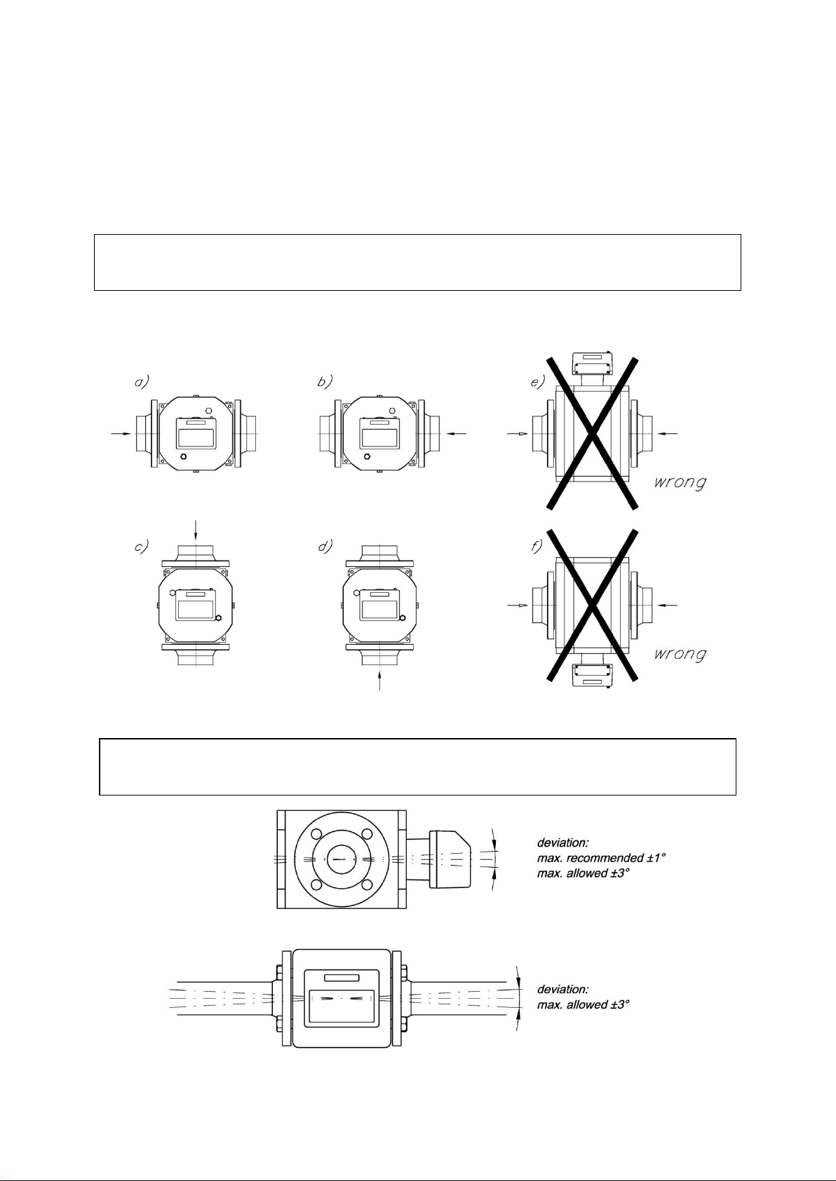
The gas meter may not be placed vertically!
Figure 12 e) & f)
VI. INSTALLATION AND OPERATION
Before installing the gas meter ensure that it is suitable for the system's operational
parameters. In particular, following type plate information should be taken into consideration:
Acceptable gas meter gauge pressure [MPa], labelled p
Maximum actual flow [m3/h], labelled Q
max
.
max
,
Rotary gas meters CGR-01 may be operated in the following four operating positions (Figure
12 a, b, c, d):
Fig. 12. Operating positions of the CGR-01 rotary gas meter.
Fig. 13. Acceptable deviations from the horizontal position of the gas meter.
CGR/IO12/MID 19
Page 21

DN
n
A B L
Weight at V
cycl
40
50
80
100
mm
mm
mm
kg
dm
3
G10p
+ +
4
165
171
277
11
0.23
G16p
+ +
4
165
171
277
11
0.23
G16w
+ +
4
184
171
296
12
0.31
G25s
+ +
4
165
171
277
11
0.23
G25p
+ +
4
184
171
296
12
0.31
G25w
+ +
4
225
171
337
14
0.50
G40s
+ +
4
184
171
296
12
0.31
G40p
+ +
4
225
171
337
14
0.50
G40w
+ +
4
295
171
407
19
0.81
G65s
+
4
225
171
337
14
0.50
G65p
+
4
295
171
407
19
0.81
G65w
+
4
391
171
503
24
1.24
G100s
+
4
295
171
407
19
0.81
G100p
+
4
391
171
503
24
1.24
G100s
+
8
295
171
407
19
0.81
G100p
+
8
391
171
503
24
1.24
G100p
+
+
8
249
241
356
25
1.29
G100w
+
+
8
314
241
421
31
2.00
G160s
+
+
8
249
241
356
25
1.29
G160p
+
+
8
314
241
421
31
2.00
G160w
+
+
8
439
241
546
42
3.34
G250s
+
8
314
241
421
31
2.00
G250p
+
8
439
241
546
42
3.34
G400s*
+
8
439
241
546
42
3.34
Gas meters should not be installed at the lowest point of the system lines, as condensate and
impurities may accumulate in that area.
The rotary gas meters can be used both indoors in stabilized temperature conditions and
outdoors (open location). In the latter case, it is recommended that the gas meter is shielded
from direct exposure to atmospheric factors (metal containers, casings, roofs, shields etc.)
The gas meter must be placed between pipes of appropriate nominal diameter, with axial
alignment of the gas meter relative to the pipes according to gas industry regulations. The
static load of the system of ducts (pipes) should not exceed values provided for in the PN-EN
12480:2004 standard.
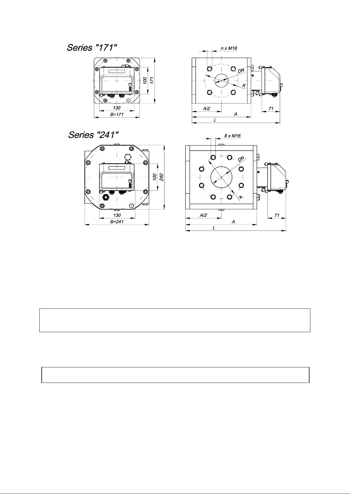
Dimensions listed in Tables 4a, 4b and 4c and illustrated in Figure 14 may be helpful when
designing the location for the installation of the gas meter.
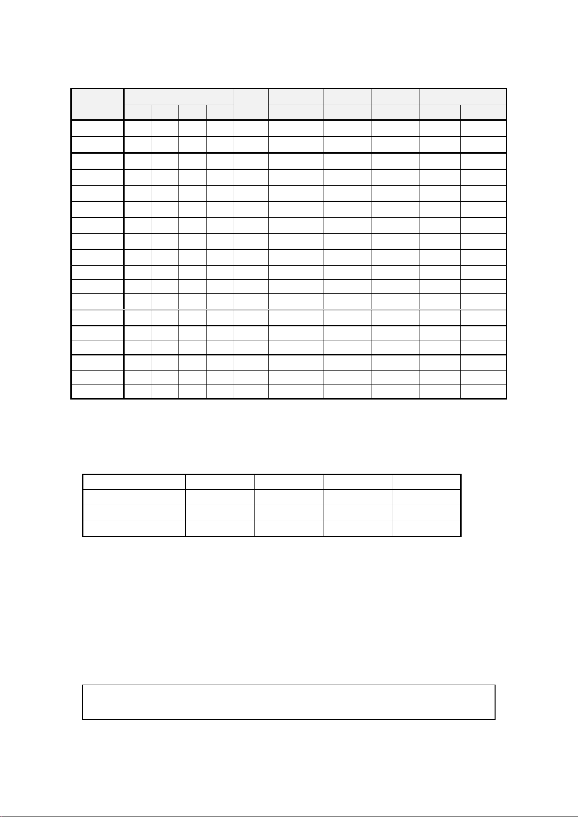
Table 4a. Basic dimensions and weights of CGR-01 gas meters in aluminium bodies.
p – basic version;
w – low-speed version (larger overall dimensions, reduced pressure loss and noise level),
s – high-speed version (smaller overall dimensions, increased pressure loss and noise level),
* – MID certificate does not apply to this version.
CGR/IO12/MID 20
Page 22
DN
n
A B L
Weight at V
cycle
40
50
80
100
mm
mm
mm
kg
dm
3
G10w
+ +
4
246
181
358
33
0.50
G16w
+ +
4
246
181
358
33
0.50
G25w
+ +
4
246
181
358
33
0.50
G40p
+ +
4
246
181
358
33
0.50
G40w
+ +
4
316
181
428
38
0.81
G65s
+
4
246
181
358
33
0.50
G65p
+
4
316
181
428
38
0.81
G65w
+
4
412
181
524
45
1.24
G100s
+
4
316
181
428
38
0.81
G100p
+
4
412
181
524
45
1.24
G100s
+
8
316
181
428
38
0.81
G100p
+
8
412
181
524
45
1.24
G100w
+
+
8
327
253
439
64
2.00
G160p
+
+
8
327
253
449
64
2.00
G160w
+
+
8
452
253
564
78
3.34
G250s
+
8
327
253
439
64
2.00
G250p
+
8
452
253
564
78
3.34
G400s*
+
8
452
253
564
78
3.34
DN40
DN50
DN80
DN100
PN 16
110
125
160
180
PN 20 (ANSI 150)
98.5
120.7
152.4
190.5
PN 25
110
125
160
190
The manufacturer is not responsible for any damages or stoppage of the gas
meter resulting from insufficient filtration of the gas flowing through the meter.
Table 4b. Basic dimensions and weights of CGR-01 gas meters in cast iron bodies.
p – basic version;
w – low-speed version (larger overall dimensions, reduced pressure loss and noise level),
s – high-speed version (smaller overall dimensions, increased pressure loss and noise level),
* – MID certificate does not apply to this version.
Table 4c. The K-dimension (fixture bolts span diameter)
Impurities contained within the gas and the system may cause mechanical damage to the
rotors and reduce the measurement accuracy. Therefore, a filter with efficacy not worse than
10 m should be placed in front of the gas meter (particularly when the flowing gas contains
large amounts of impurities). In addition, the inflow section of the system should be carefully
cleaned and blown through before installing the gas meter, and a conical sack filter should be
placed at the inlet of the inflow section; the filter should be removed after 1 2 months of
operation. If the filter is not removed, monitoring of the filter impurity level should be
provided by means of pressure drop measurements or regular check-ups. If clogged, the sack
filter may be destroyed by the gas pressure, and filter residue may seriously damage the gas
meter.
CGR/IO12/MID 21
Page 23
Before final installation of the gas meter ensure it is properly oriented, i.e. that the
arrow on the meter body points in the direction of the gas flow.
Do not exceed the torque of 160 Nm when tightening the screws!
Fig. 14. Basic dimensions of CGR-01 rotary gas meters.
The user should be aware of certain risks associated with changes in the gas flow intensity. If
the gas flow was relatively low for a long time after system initiation, the assembly-related
contaminants (e.g. welding residues) are retained in front of the gas meter. Only after the flow
is significantly increased, the contaminants may be swept away by the gas, causing gas meter
damage. For this reason, the sack filter may prove useful in the period in which maximum
system capacity is being reached. In all cases, protection of the gas meter from mechanical
damage is in the user's best interest.
The gas meter should be connected to the pipeline flanges using the factory-supplied M16x70
set screws or M16x45 bolts of appropriate length (mechanical property class 5.8) Appropriate
seals should be selected for specific flange types and nominal pressures.
The gas meter should be primed with oil after installation and before start-up. Oils supplied
and recommended by the gas meter manufacturer should be used. Following oils may be used
with gases listed in Table 1:
Lubrina L12 rotary gas meter oil (distributed by Common S.A.);
VR09 rotary gas meter oil (distributed by Common S.A.);
Shell Tellus T15.
CGR/IO12/MID 22
Page 24
Other types of oils should be used for lubrication of gas meters in cases when the gas
flowing through the meter is other than one of the gases listed in Table 1. In such
cases, consult the oil type with the manufacturer of the gas meter!
position
series "171"
series "241"
"a" or "b"
30 mL
50 mL
"c" or "d"
50 mL
85 mL
position
series "171"
series "241"
"a" or "b"
10 mL
20 mL
"c" or "d"
15 mL
30 mL
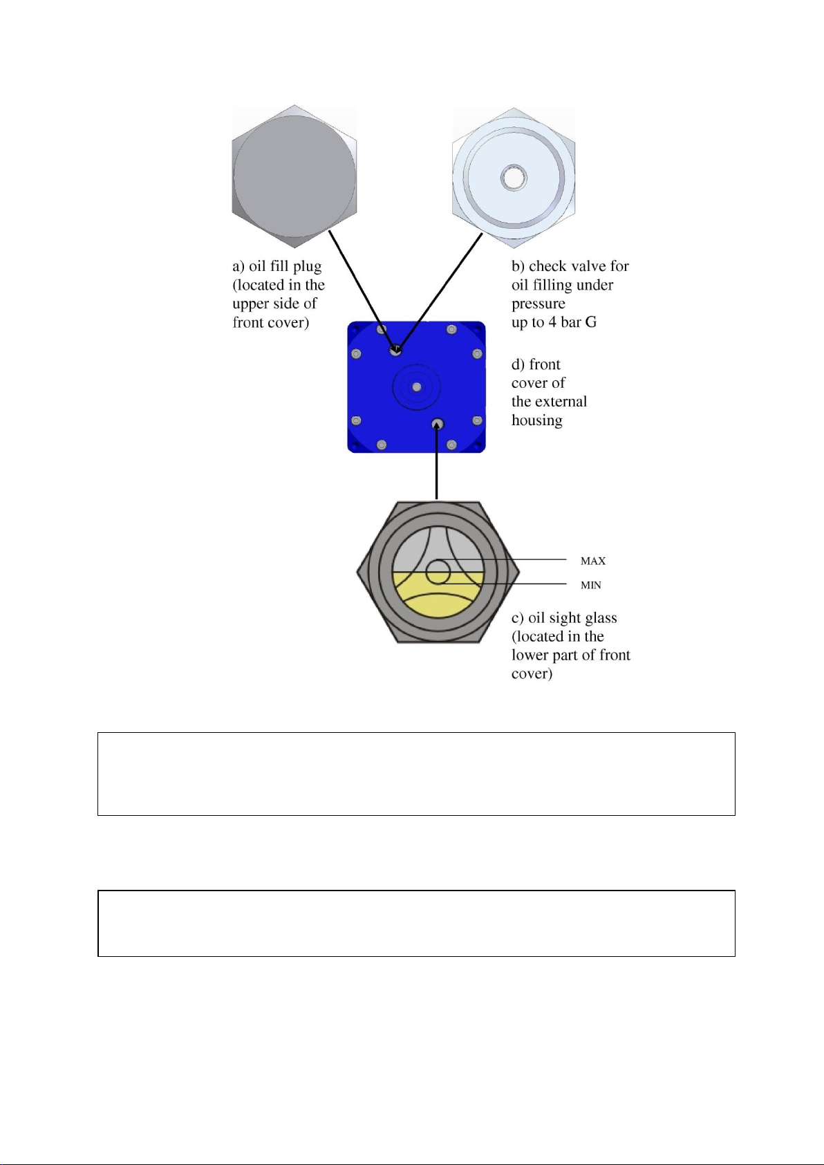
Oil level should be controlled during priming and subsequent refills. The level of oil in the
gas meter should be visible in the control plug window, between the MIN and MAX lines
(Fig. 15c). The control plug is also used as a drain plug and should be placed in the bottom
opening of the front cover. If the control plug is located in the top opening of the cover, it
should be removed and replaced with the oil filler plug (Fig. 15a).
Approximate amounts of priming oil, depending on the gas meter position and size (Fig.
12.):
Volume required to refill the oil between the Min and Max lines, depending on the gas meter
position and size (Fig. 12):
Depending on the embodiment, the gas meter may be equipped with:
oil filler plug (Fig. 15a) – standard version,
pressure oil refill valve (Fig. 15b) – special version.
Each standard CGR-01 gas meter may be transformed into special version by installation of a
pressure valve and an oil refill assembly.
If the gas meter is equipped with an oil filler plug (Fig. 15a), oil may be poured into the gas
meter using the top opening in the front cover after removal of the plug.
CGR/IO12/MID 23
Page 25
Caution!
Gas pressure inside the gas meter should be reduced to atmospheric level before
removal of the oil filler plug.
Caution!
The pressure valve must not be removed when the gas meter is installed in the system
under working pressure
Fig. 15. Oil filler plug.
If the gas meter is equipped with a pressure valve (Fig. 15b), oil may be refilled
without reducing the system pressure to atmospheric level. Detailed information is presented
in Section VIII. Additional equipment.
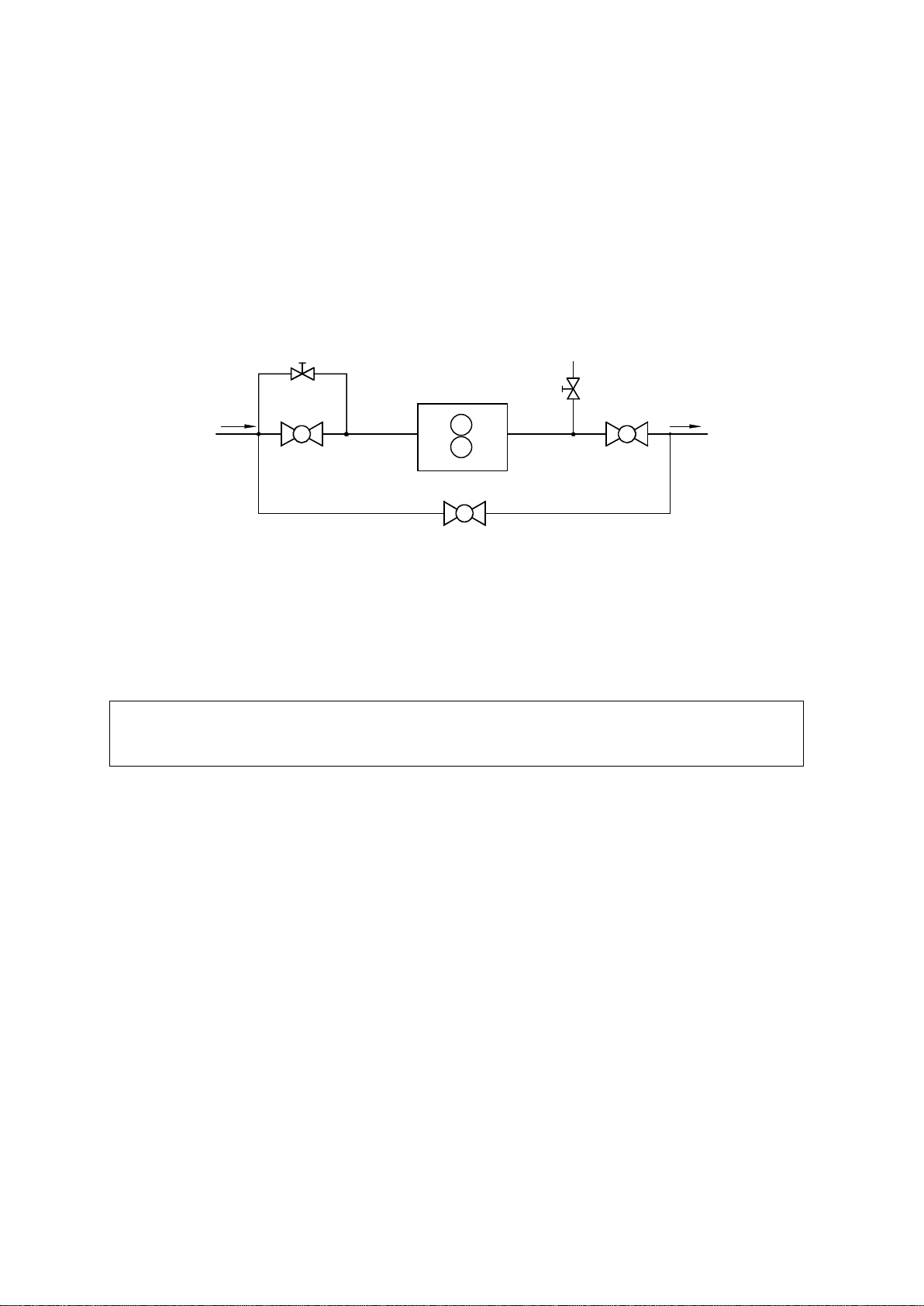
In a typical installation setting, i.e. in a bypass system (Fig. 16), the gas meter start-up
procedure should proceed as follows:
1. The gas meter is installed with valves 1, 2, 5 being closed and the bypass valve 4
remaining open. The blow-off valve 3 remains open after system the system is degassed.
CGR/IO12/MID 24
Page 26
1
2
3
4
5
Caution!
Drain the oil before uninstalling the gas meter!
2. After levelling the gas meter and tightening the bolts connecting the gas meter to the
pipeline, the gas meter should be primed with oil according to instructions.
3. Next, air should be removed from the system using valve 5, according to appropriate
regulations. Valve 3 should remain open.
4. After deaeration, valve 3 is closed and system gas pressure is equilibrated with pressure
increase rate not larger than 30 10 kPa/s.
5. Valve 5 is closed when the gas meter counter stops indicating the flow (associated with
pressure equilibration).
6. Valve 1 is opened, followed by valve 2.
7. Bypass valve 4 may be closed after the valve 2 has been opened in full.
Fig. 16. A diagram of a bypass measurement system
When removing the gas meter, the above steps should be followed in reverse order, i.e.
1. Bypass valve 4 is closed first
2. Valve 2 is closed, followed by valve 1.
3. The measurement segment is slowly degassed using the blow-off valve 3, with pressure
drop not larger than 30 10 kPa/s.
The same principle should be followed in other installation settings, i.e. the flow of the gas
through the gas meter should be opened or closed very slowly. Rapid change in the flow
caused by sudden opening of the valve may damage the rotor bearings due to a large
difference of pressure upstream and downstream of the rotor.
If there is a risk of gas meter overload (i.e. exceeding Q
by more than 25 %), during
max
exploitation, the use of a restrictor orifice is recommended. The orifice should be installed at a
distance of 510 nominal diameters (DN) behind the gas meter. The orifice dimensions are
selected individually on the basis of the nominal diameter and gas flow, pressure and
temperature. Common S.A. may design and deliver appropriate orifice at customer's request.
Counter readout correctness should be checked after installing the gas meter. Every barrel of
the counter should turn smoothly and a full turn of a barrel should turn the neighbouring left
barrel by 1/10 of a full turn.
CGR/IO12/MID 25
Page 27
VII. OPERATION MONITORING, MAINTENANCE, FAILURES, REPAIRS
In any doubt regarding the correctness of gas meter readings, the gas meter should be
removed from the system and submitted to an appropriate laboratory for verification of its
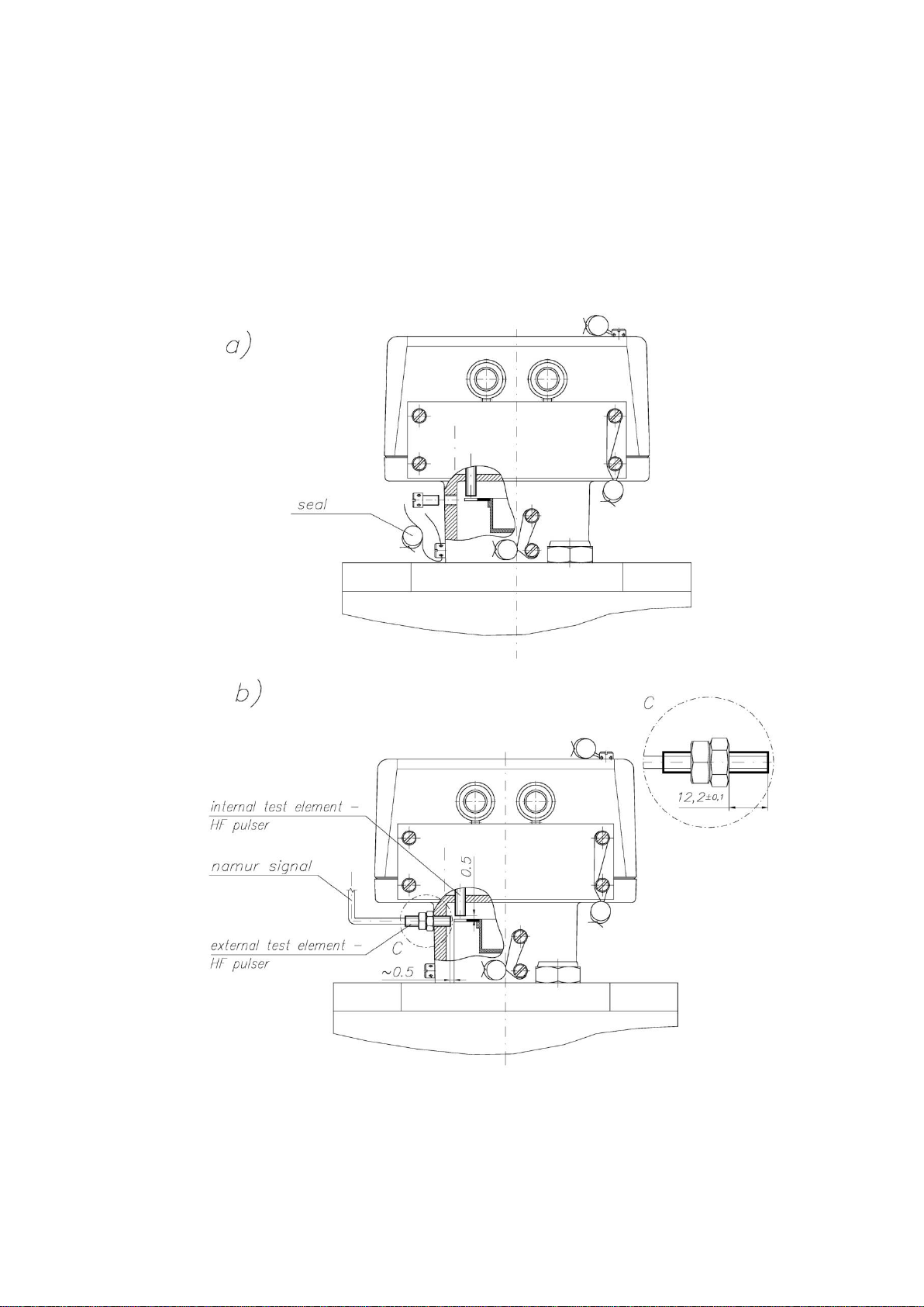
metrological characteristics. The test may be performed using the control element, without
breaking the legal approval seal. One of the inductive emitters installed in the counter may act
as a control element. If the counter is not equipped with a HF emitter, an external HF emitter
(type Bi1-EG05-Y1 by Hans Turck GmbH) should be connected to act as a control element
(Fig. 17).
Fig. 17. Connection of the control element.
The external control element is installed in a special M5-threaded opening in the cylindrical
part of the counter, after removing the protection seal no. 7 and the blocking screw (Fig. 17a.).
The control element should be screwed in to a depth allowing for a proper (i.e. consistent with
CGR/IO12/MID 26
Page 28

Oil refills may be made only when the gas flow is shut off.
Gas meter repairs may be performed only by the manufacturer
or a company authorized by the manufacturer.
Users must not attempt to repair the gas makers themselves!
the Namur standard) emitter signal to be obtained. This should be achieved with ca. 0.5 mm
spacing between the emitter head and the inductive element (Fig. 17b). After completion of
the test and removal of the control element, the hole should be tightly closed using a plug. A
protection seal should be placed on the plug.
The gas meters CGR-01 are complete with a system for lubrication of rotors and inner gears.
The remaining mechanisms are furnished with bearings complete with lubricant reserves.
Therefore, the only activity required for the maintenance of the gas meters is the monitoring
of the oil level and possibly oil refill. Only oils supplied and recommended by the gas meter
manufacturer should be used for oil refills.
If the gas meter is equipped with an oil filler plug (Fig. 15a), gas pressure should be reduced
to atmospheric level before the oil refill procedure. The oil may be poured through the top
opening in the front cover of the gas meter after removal of the plug.
If the gas meter is equipped with a pressure valve (Fig. 15b), oil may be refilled without
reducing the system pressure to atmospheric level. Detailed information is presented in
Section VIII. Additional equipment.
Dust and other impurities may be removed from the gas meter surface using a cloth soaked in
soap and water. Do not clean with solvents or other chemicals.
In case of any incorrectness in gas meter operation (e.g. irregular counter work or counter
stoppage, elevated noise, crackling, oil leaks), the gas meter should be immediately submitted
for repair.
Repairs associated with breaking the verification seals require another legal approval of the
gas meter.
The CGR-01 gas meters are subject to manufacturer's warranty. The warranty proceedings are
in line with the general trade law regulations.
CGR/IO12/MID 27
Page 29
Caution!
Pertains to systems with maximum gas pressure of 0.5 MPa.
Before starting the oil refill procedure, stop the flow of the gas in the measurement
system and wait several minutes until the oil level is stabilized in the gas meter.
VIII. ADDITIONAL EQUIPMENT
Oil refills in pressurized conditions.
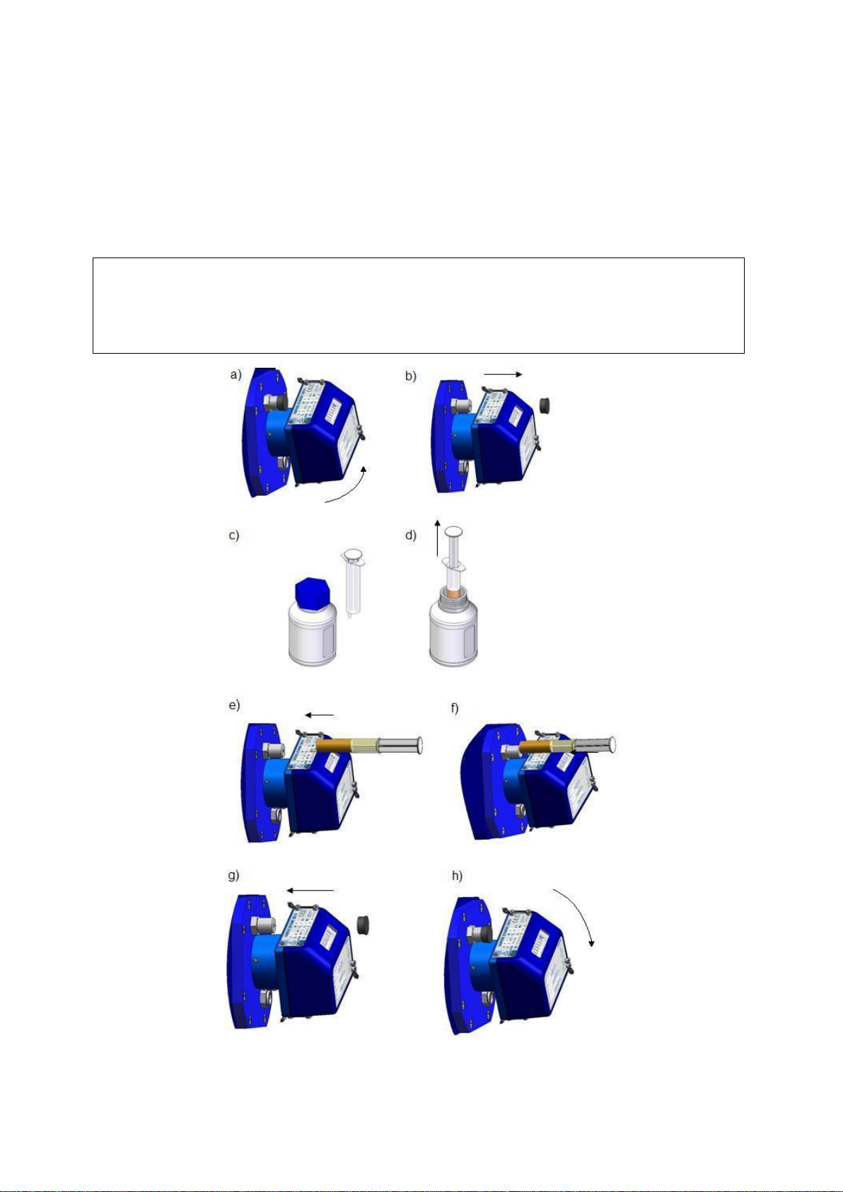
It is possible to refill oil without the need to reduce the gas pressure to the atmospheric level
when using a special version of the CGR-01 gas meter equipped with a pressure valve (Fig.
15b). A “single use” syringe supplied with the oil container is used for pumping the oil into
the valve.
Fig. 18. CGR-01 gas meter oil refill procedure in pressurized conditions.
CGR/IO12/MID 28
Page 30
The sequence of steps when pumping the oil (Fig. 18):
a. Turn the counter head so that the pressure valve is easily accessible;
b. Remove the cap protecting the valve from contamination;
c. Prepare the oil pumping kit;
d. Draw appropriate amount of oil into the syringe;
e. Insert the syringe tip into the pressure valve opening;
f. Pump an appropriate amount of oil into the valve while monitoring the oil level in the
inspection window;
g. Remove the syringe tip from the valve, replace the protective cap, return excess oil
from the syringe into the container;
h. Return the counter head to its previous, readout-convenient position.
Connecting a volume converter to the gas meter.
Due to tariff requirements, it is often required (or recommended) for the gas meters to be
operated together with electronic devices such as data loggers or volume converters and data
transmission devices. Common S.A. manufactures such devices, e.g. battery/grid-powered
volume converters CMK-02 and data loggers CRS-03, CRI-02. Common S.A. may deliver
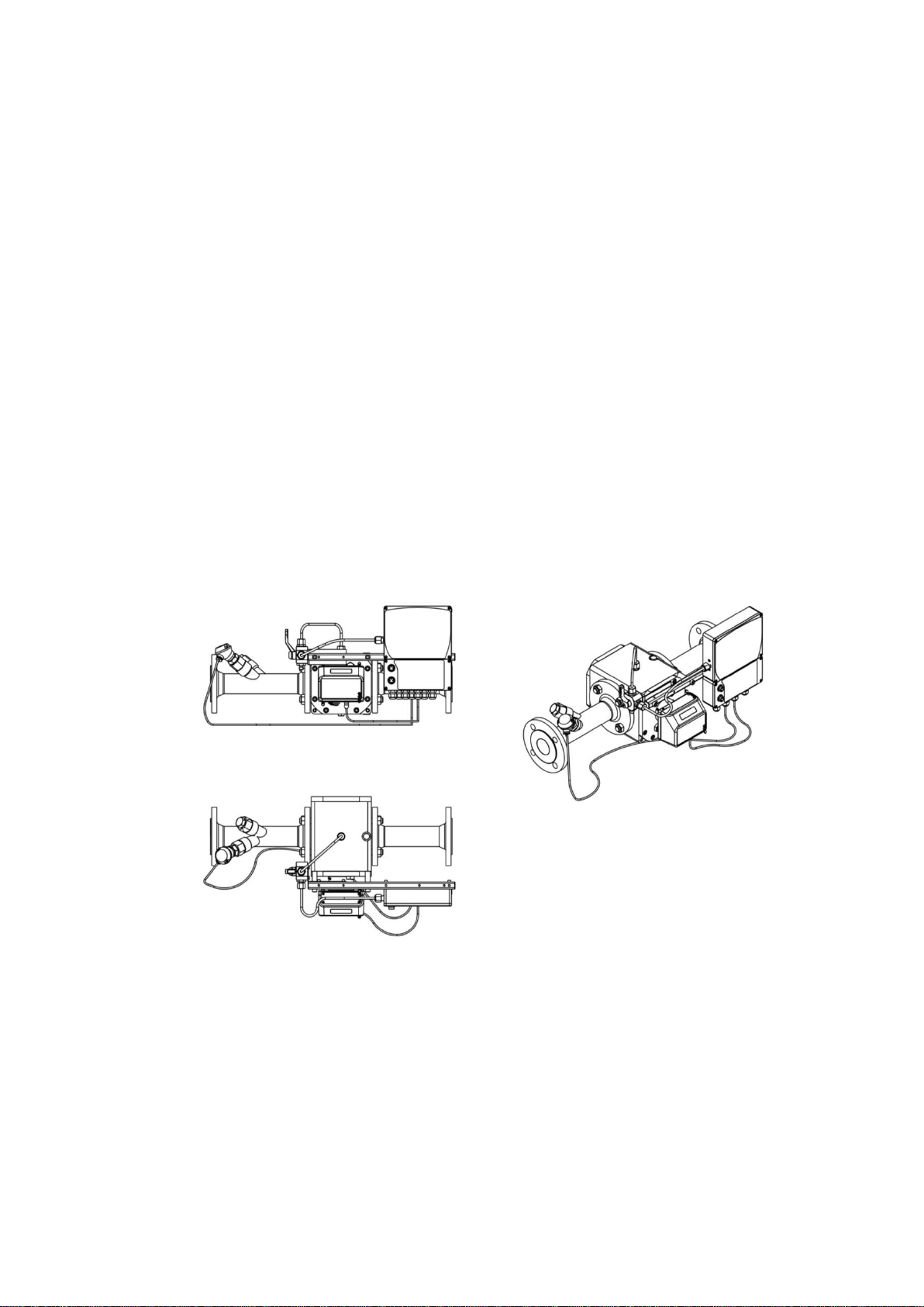
these devices by special orders, together with installation services. Figure 19 presents an
example installation of this type.
Fig. 19. An assembly consisting of a CGR-01 gas meter and a CMK-02 volume converter
(the converter is installed on the gas meter)
The converter receives three input signals: the flow signal (from the low- or high-frequency
pulse emitter), the pressure signal and the temperature signal. The pressure signal is collected
at the pulse pressure measurement outlet. It is recommended that the pressure pulse is
obtained through the three-way CKMT valve allowing the pressure being disconnected from
the sensor for the removal and inspection thereof.
CGR/IO12/MID 29
Page 31
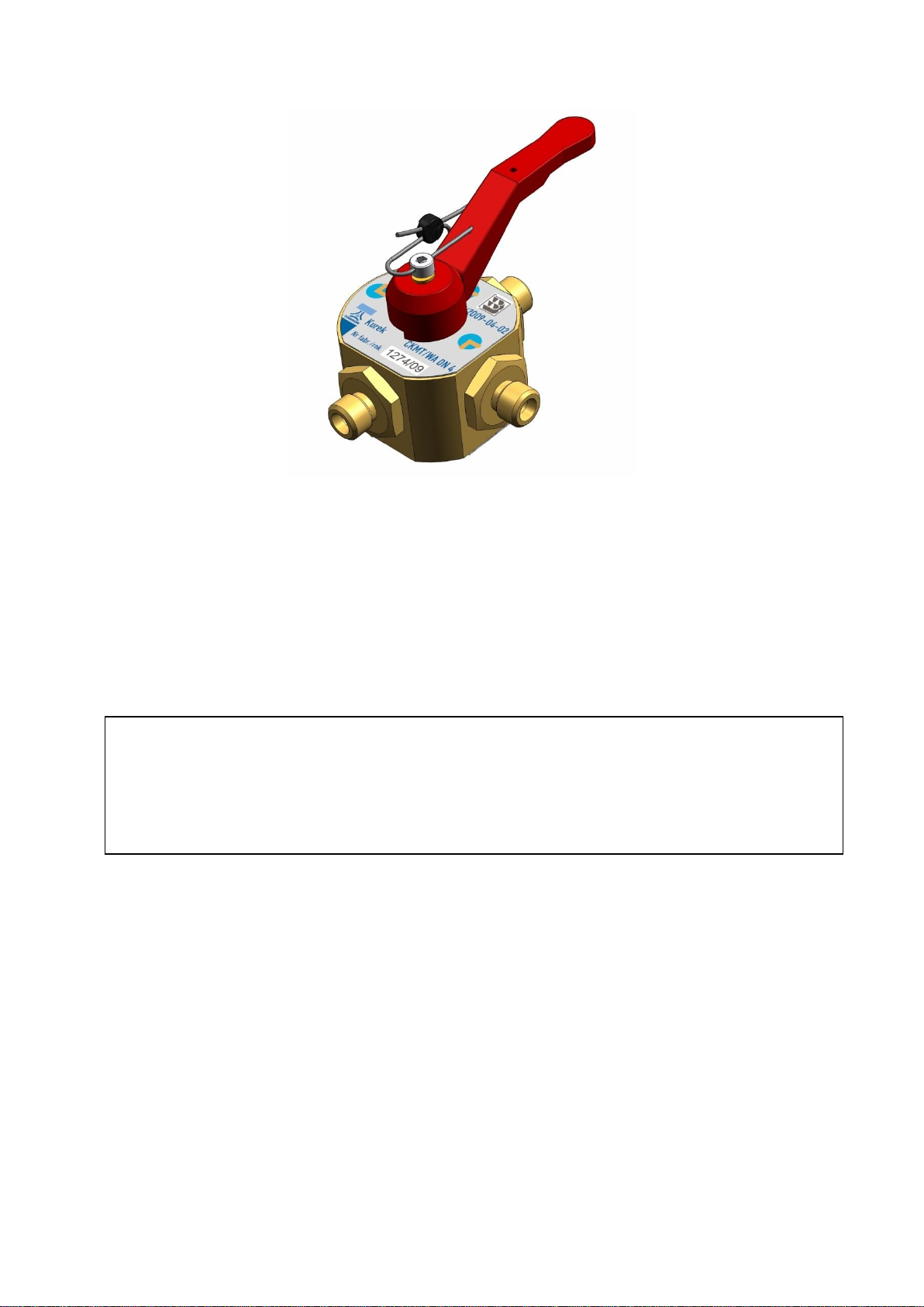
One should keep in mind that all activities associated with connection of additional
equipment to the gas meter are also associated with breaking the protection seals and thus
may be performed only by representatives of the gas company or the manufacturer. Unused electrical outlet sockets must remain plugged with factory-made plugs and installation seals.
Fig. 20. A three-way CKMT valve
The valve handle position is secured by a seal. The valve may be operated only under
supervision of the gas company representative; after operation, the handle is again secured
with an installation seal.
The temperature signal is collected from the emitter installed in appropriate temperature
pocket in the inflow section (upstream the gas meter) (Fig. 19) or in a temperature pocket in
the gas meter itself.
CGR/IO12/MID 30
Page 32
After ending the usage period, the gas meter should under no
circumstances be discarded into municipal waste containers. The
Waste Act of 27 April 2001 imposes an obligation for selective
collection of metallic waste. Gas meters should be best returned to
the manufacturer who would recycle them in an appropriate
fashion. If unable to do so, the user is obliged to deliver the gas
meter to an appropriate recycling point.
Gas meter packaging should never be discarded into municipal
waste containers. The packaging has been appropriately labelled;
pursuant to the Act of 11 May 2001 on packaging and packaging
waste, the user is obliged to submit the packaging for an
appropriate recycling process.
IX. LIST OF STANDARDS AND TECHNICAL SPECIFICATIONS
PN-EN 12480:2005 (EN 12480:2002)
Gas meters – Rotary displacement gas meters
PN-EN 12480:2005/A1:2008 (EN 12480:2002/A1:2006)
Gas meters – Rotary displacement gas meters
PN-EN 13463-1:2010 (EN 13463-1:2009)
Non-electrical Equipment For Use in Potentially Explosive Atmospheres - Part 1:
Basic Method And Requirements
PN-EN 60079-0:2009 (EN 60079-0:2009)
Explosive atmospheres – Part 0: Equipment – General Requirements
PN-EN 60079-11:2010 (EN 60079-11:2007)
Explosive atmospheres – Part 11: Equipment Protection By Intrinsic Safety 'I'
PN-EN 60947-5-2:2011 (EN 60947-5-2:2007)
Low-voltage switchgear and controlgear – Part 5-2: Control circuit devices and
switching elements – proximity switches.
PN-EN 60947-5-6:2002 (EN 60947-5-6:2000)
Low-voltage switchgear and controlgear – Part 5-6: Control circuit devices and
switching elements – DC interface for proximity sensors and switching amplifiers
(NAMUR)
WUDT/UC/2003
Requirements of Office of Technical Inspection – Pressure Equipment
.
Note: Common S.A. reserves the right to modify the design of the gas meters while retaining the compliance
with relevant standards and requirements regarding accuracy and safety of operation.
CGR/IO12/MID 31
 Loading...