

Page 1

Commodore
Disk Drive
Technical Manual
Model
8250LP
SFD-1001
These
documents
are
for
repair service
information
only.
Part
numbers
are
for
reference
only.
Only
parts
on
current
dealer
parts
list
are available.
No
license
is given
for
any
use
by
possession
of
these
documents
and
may
not
be
reproduced
in
any
form
without
the
written
approval
of
Commodore
Electronics
Limited.
C::
commodore
COMPUTER
Page 2

CONTENTS
I.
GENERAL
rL
CAPACITY
m.
MEDIA
IV.
ENVIRONMENTAL
V.
RELIABILITY
VI.
POWER
VU.
DRIVE
VlII.
INTERFACE
IX.
SUGGESTED
GENERAL
CONTROL/DATA
TIMING
REQUIREMENTS
X. PHYSICAL OUTLINE
XI.
PARTS
LIST
(1)
Page 3
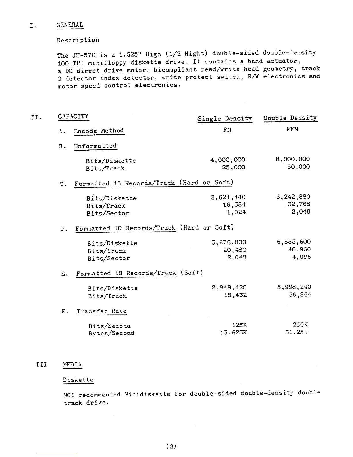
I.
GENERAL
II.
Description
The
JU-570
is
a
1.
625"
High
(1/2
Hight)
doub
le-sided
double-clensi
ty
100
TPI
minifloppy
diskette
drive.
It
contains
a
band
actuator,
a
DC
direct
drive
motor,
bicompliant
read/write
head
geometry,
track
o
detector
index
detector,
write
protect
switch,
~/W
electronics
and
motor
speed
control
electronics.
CAPACITY
Sin~le
Density
Double
Density
A.
Encode
Method
n{
~tF1>1
B.
Unformatted
Bits/Diskette
4,000,000
8,000,000
Bits/!rack
25
,000
50,000
C.
Formatted
16
Records/Track
(Hard
or
Soft)
Bits/Diskette
2,621,440
5,242,880
Bits/l'rack
16,384
32,768
Bits/Sector
1,024
2,048
D.
Formatted
10
Records/Track
(Hard
or
Soft)
Bits/Diskette
3,276,800
6,553,600
Bits/Track
20,480
40,960
Bits/Sector
2,048
4,096
E.
Formatted
18
Records/l'rack
(Soft)
Bits/Diskette
2,949,120
5,998,240
Bi
ts/Track
18,432
36,864
F.
Transfer
Rate
Bits/Second
125K
250K
Bytes/Second
15.f)25K
31.
25K
III
~!E.DIA
Diskette
Mcr
recommended
Minidiskette
for
double-sided
double-density
double
track
dri
'.-e.
(
2)
Page 4
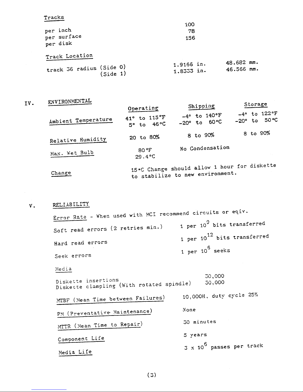
Tracks
per
inch
per
surface
per
disk
Track
Location
track
36
radius
(Side
0)
(Side
1)
IV.
Et'JVIRONHENTAL
Operatin~
Ambient
Temperature
41°
to
115°F
5°
to
46°C
Relative
Humidity
20
to
80%
Ha.'C.
\{et
Bulb
BO°F
29.4°C
100
78
156
1.9166
in.
1.8333
in.
Shippii1~
_4°
to
HO°F
-20°
to
60°C
8
to
90%
48.682
nun.
46.566
[!I.ln.
Stora~e
_4°
to
122
c
F
-20°
to
50°C
8
to
90%
No
Condensation
Change
15°C
Change
should
allow
1
hour
for
diskette
to
stabilize
to
ne~
environment.
v.
RELIABILITY
Error
Rate
-
\'ihen
used
wi
th
~'CI
recommend
circuits
or
eqi
v.
Soft
read
errors
(2
retries
min.)
n
1
per
10~
bits
transferred
Hard
read
errors
1
per
10
12
bits
t.ransferred
Seek
errors
1
per
10
5
seeks
:-!edia
Diskette
insertions
Diskette
clnmpling
(With
rotated
spindle)
30,000
30.000
~iTBF
(~Iean
T ime
bet\~een
Fai
lures)
10,OOOH.
duty
cycle
25%
p~
(Preventativ~
~aintenance)
None
~rrTR
(;o!ean
Time
to
Repair)
30
minutes
Component
Life
5
years
~!edia
Life
:;
x
10
6
passes
per
track
(3)
Page 5
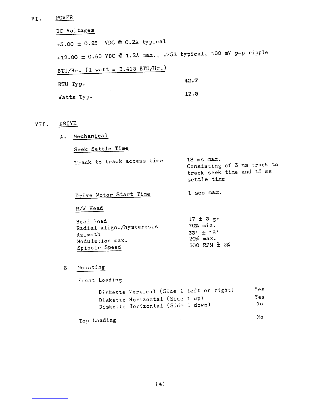
VI.
PO\vER
VII.
DC
Voltages
+5.00
±
0.25
VDC
@
0.2A
typical
+12.00
±
0.60
VDC
@
1.2A
m~~.,
.75A
typical,
100
mV
p-p
ripple
BTU/Hr.
(1
watt
=
3.413
BTU/Hr.)
BTU
Typ.
Watts
Typ.
DRIVE
A.
~Iechanical
Seek
Settle
Time
Track
to
track
access
time
Drive
Motor
Start
Time
Rjlf
Head
Head
load
Radial
align./hysteresis
Azimuth
(-Iodulation
m~~.
Spindle
Speed
B.
~lour1ting
F:-on1:
Loading
42.7
12.5
18
ms
m~~.
Consisting
of
3
ms
track
to
track
seek
time
and
15
ms
settle
time
1
sec
m~"C.
17
±
:5
gr
70%
min.
33'
±
18'
20%
max.
300
RP~1
~
3%
Disket~e
Ver1:ical
(Side
1
left
or
right)
Yes
Disket~e
Horizontal
(Side
1
up)
Yes
Diskette
Horizontal
(Side
1 do",-n)
No
Top
Loading
:-;0
Page 6
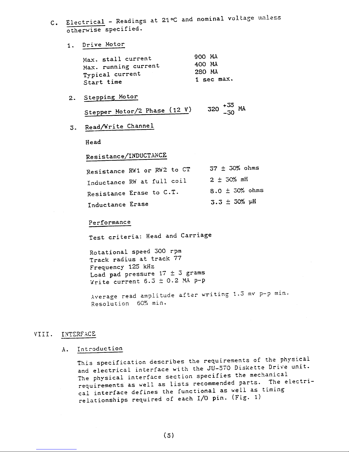
C.
Electrical
-
Readings
at
21°C
and
nominal
volta~e
unless
othen.ise
specified.
1.
Dri
ve
~Iotor
H3-'C.
stall
current
~t3-'C.
running
current
Typical
current
Start
time
2.
Stepping
:'1otor
Stepper
Motor/2
Phase
(12
V)
3.
Read/Write
Channel
Head
Resistance/1NDUCTANCE
Resistance
R\'i1
or
R\y-2
to
CT
Inductance
R\i
at
full
coil
Resistance
Erase
to
C.T.
Inductance
Erase
Performance
900
MA
400
HA
280
K.\.
1
sec
m3-'C.
1-35
320
-30
~1A
37
±
30%
ohms
2
±
3aYo
mH
8.0
_ 30%
ohms
3.3
_
30%
1J.H
Test
criteria:
Head
and
Carriage
Rotational
speed
300
rpm
Track
radius
at
track
77
Fre~uency
125
kHz
Load
pad
pressure
17
±
3
grams
',rri
te
current
6.3
::
0.2
M.A
p-p
Average
read
amplitude
after
writing
1.3
mv
p-p
min.
Resolu~ion
60%
min.
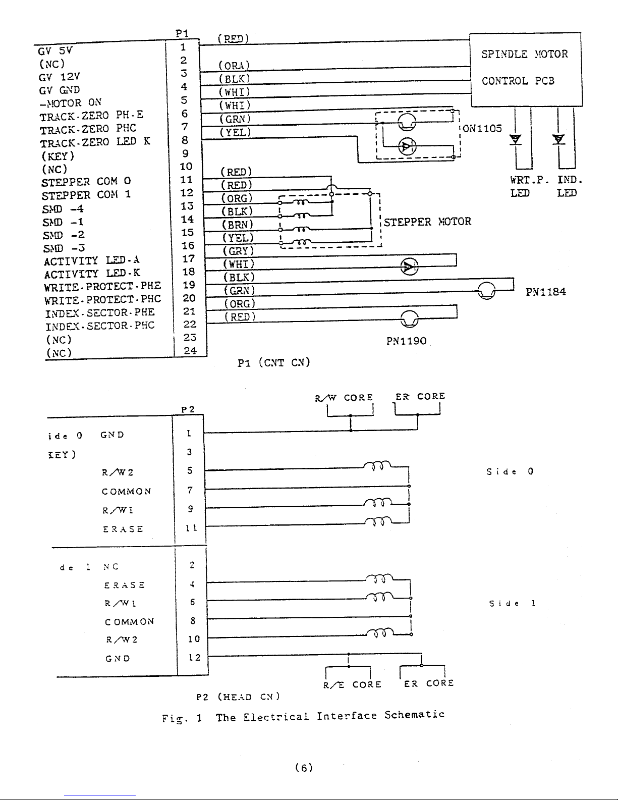
VIII.
I~T£RFACS
A.
Introduction
This
specification
describes
the
requirements
of
the
physical
and
electrical
interface
with
the
JU-570
Diskette
Drive
unit.
The
physical
interface
section
specifies
the
mechanical
requirements
as
well
as
lis~s
recommended
parts.
The
electri-
cal
interface
defines
the
functional
as
well
as
timing
relationships
required
of
each
I/O
pin.
(Fig.
1)
(5)
Page 7
GV
5V
(NC)
GV
12V
GV
Gi"iD
-HOTOR
ON
TRACK·
ZERO
PH·E
TR..,l"CK·
ZERO
PHC
TR..\CK·
ZERO
LED
K
(KEY)
(NC)
STEPPER
COM
0
STEPPER
CO/>!
1
Sl-ID
-4
S?-ID
-1
S:-ID
-2
Sl-ID
-3
ACTIVITY
LED·..\.
ACTIVITY
LED·K
WRITE·PROTECT.PHE
~~ITE·PROTECT·PHC
I~uLX·SECTOR·PHE
INDLX·SECTOR·PHC
(NC)
I
(NC)
ide
0
GND
tEY)
R/WZ
COMMON
R/Wl
E~ASE
d
e
1
NC
ER.ASe:
R/,N
1
COMMON
R/W2
GNO
P1
..
1
2
3
45
6
7
8
9
10
11
12
13
1415
16
17
18
19
20
21
22
23
24
PZ
1
3
5
7
9
1 1
2
4
6
8
10
12
.
(HEn
)
(ORA)
SPINDLE
~!OTOR
(BLK)
CONTROL
PCB
(\,HI)
(\"HI)
(GRN)
r------
--~
~
~
~
r'\
'I
(YEt)
'~'ONll05
l
: t.:1\ :
I
~
!
~--------
-
(RED)
(RED)
fl"I.
(ORG)
r-
----<
-----c
~,
..
-
I
(BUO
I
I
,.-
(BRN)
I
:
STEPPER
~iOTOR
(YEL)
..
I ..........
(GRY)
'-_!V
____
(WHI)
(BLK)
(G&'l
)
(ORG)
(
RED)
Pi
(C:--lT
C:--l)
R/W
I
•
•
____
..r.
tCi\
'C)I
,---....
PN1190
ER
CORE
I
~
.~
~------------------~
I
n
R/E
CORE
ER
CORE
J
J
WRT.P.
IND.
LED
LED
-Q-J
PN1184
Side
0
Sid
e 1
P2 (HE.;'O CN)
Fi~.
1
The
Electrical
Interface
Schematic
Page 8

B-1.
RjI,{
Head
Interface
Connector
P2
provides
the
physical
interface
to
the
magnetic
head
as
shown
in
figure
2.
c:J
1
2
c:J
3 4
Q
c::J
5
6
c::J
7
B
c::J
9
10
c::J
11
12
3:
KEY
Fig.
2
P2
Connector
B-2.
Schematic
P2
5)
R./W2
C
RED)
l)GND
(YEL)
11)
ERAS
c:
(Grt.!i)
i
~
R/Vi
CT(WHT)
9 )
R./Wl
(ELK)
10)
R/W2
(RED)
12)
GND
(YE
L )
4)ER.:SE
(GRN)
8)
R~N
CT(WHT)
6 )
R/Wl
(
ELK)
(7)
Head
Core
~
7
~.---?--::t~
7
Side
0
Side
1
Page 9

B-3.
8-4.
Connector
Requirements
Housing
Contacts
PCB
Header
Honda
HKP-12F02
Honda
HK?-F303
Honda
FFC-12TLBW1B#3
The
w~ITE opera~lon
utilizes
both
read/write
coils
sequentially,
where
each
~ritten
bit
is
directed
to
alternate
read/write
coil,
creating
a
change
in
the
direction
of
current
flow
through
the
read/write
head.
The
required
current
is
6.3
±
.2
ma
peak
to
peak,
or
3.15
±
.2
ma
base
to
peak
on
all
tracks.
It
is
recom-
mended
that
the
write
current
transitions
are
within
0.5%
from
leading
edge
to
leading
edge.
Proper
write
damping
must
be
considered
during
design
for
write
transitions.
Note:
The
head
must
be
loaded
for
proper
write
operation.
4-2SA720
or
Eq.
4-MA162
or
Eq.
P2-9
·
~
i
>>---3
tZ2k
62k~
I
~ Sid~O
I
~
HEAD
P2-5
..,
)! •
I
>>---J
-WRITE
DATA
1
J-
'f
I
pt
~
2k
l~
I
-----:::~\'\.
150
22k
6?l.-
j""'-'
Side
1
2~~
332
~
~
332
,-.-!-_1_~_
....
I
__
---,L~,-··
..
pZ)10i.
?
HS.l.O
1:;
I
I
l~
•
7i
7.
AA
I?
I
WRITE
OA.Tf>..
J
_______
~~~.A-1_~----~
SV
Oi----
.... ,
--.....,V
l
1
P2-i
T~
0
?2-8
~
22k
CONSTANT
r
I
C~R~E~~
SOURCE
[0
;>
-
3.J.
_
0.1
rnA
iii
I
!
I
Lw
1
WRITE
GATE
6~1
~n-"I,I,--l
L..;L-J
6.30
I
I
E:X?
.....
NOED
WRITE
GA7E
O
II
I~:
-~I-----"
I
l~
I "
I
----------1-5~1
M
i
Zt
~+br----
...
,
-{:i~K---+--':::i
12VA
-S[OE1
SELECT
----------~I
\,I.\tr-----V·,~~--,
I'
470
l.Si<
I
12i
13
1 ; 0.01.::
m
i77
1TT"
Fig.
3 A
RECO~~fE
. .'mED
I~TEP..FACE
FOR
\~~ITE
OPE.RATIO."!
(8)
Page 10

B-5.
Side
0
Head
Side
1
Head
The
READ
operation
occurs
when
the
head
is
loaded
and
data
has
been
previously
recorded
on
the
track
of
interest.
Using
an
S/A
diskette
the
minimum
differential
amplitude
of
1.3
mY
peak-
to-peak
occurs
on
T~~
77
at
a
frequency
of
125
kHz.
A maximum
signal
amplitude
of
20
mY
occurs
on
TRK
00
at
a
frequency
of
625
kHz.
The
customer
is
cautioned
to
use
propzr
clamping
for
the
read
operation.
A
recommended
interface
is
shown
in
figure
4.
~
~n,
4-MA
162
:<
~
'tt'
'"
orEq
r
I
12VA
2-9.09k
1~
•
!1
p
~e
~.
--~~--'~~~-----<:<~----~
i
//
I
P2
-:.
0
,.-..----.-----
..
"
..
Diffe!"encial
Read
Que
:\mll.
I
p))>-I
______
l_.5_._:.:
...:.t
___
-<fo--l._S_k_:~r/-,..·-__:J>~
\
470
)1
Selected
5
ice
is
OV
P2-3
(or
ReAd
Qperacion
'----"7~>---------------...------\\'Y-.
-----,:;.:;..
-\70
Fig.
4 A
RECO~~~~DED
I~TE~~ACE
FOR
READ
OPE~\TION
XOTE:
Figure
3
and
4
interface
circuits
are
valid
only
when
used
in
connection
with
each
other.
(9)
Page 11

B-6.
The
ER~SE
COIL
requires
a
DC
curren~
of
40
ma
± 4 ma
energized
during
any
write
operation.
Both
erase
current
and
write
current
should
be
started
and
ended
simultaneously.
A
recommended
interface
for
the
erase
coil
is
sho~n
in
figure
5.
Delaied
Wri
te
Gate
90gn
1/8W
l~
+v
~
A,~
__
~
__
~
~;4n
1/8W
l~
+v
to
Fig 3 ______________
-.1
oE------.-.i
S
id~
0
I
I
I
I
P2-8
c::
Side
1
1£=40
::: 2
MA
ERASE
COIL
Fig.5
A
RECO~!}IE.'mED
INTERFACE FOR EAHSE
COIL
(10)
Page 12

C-1.
Stepping
Motor,
Drive
Motor,
Write
Protect,
Track.OO
and
ACTIVE
LED
Interface
Connector
Pl
provides
the
physical
interface
to
stepper,
drive
motor,
write
protect,
Track
OO,and
Inde:.:.
EO US
n"G
.
c;::
~.
~:-:-'
....
-"
'--
!'l
-.~
%4
I I I I
I
til
,(
1'-1
a a
L
__
\\_::Ji
fi
-
!
I I
=-
r
(?>Q.
I I_I
I I
-;+-,--
t.~4
II
i~~~
~~
I
I
_I
C-
I
I
I _
-...::..
,
,
r-------
....
-'""""-----.
........
--
.l'1--
. I
'i
~
L-
..
_____
I
~
!;
'~I~
Fig.6
Connector
Requiremen~s
Housing
Contacts
PCB
header
Honda
Honda
Honda
HKP-24F02
HKP-F403R
HKP-l0~12L
FFC-24TLB\\'lB
#9
(11
)
Page 13

C-2-
Step
Motor
Input
Requirement
The
motor
is
a
bifilar
wound,
four
phase
stepper
which
generates
a
1_80 step
with
single
phase
stepping.
BROWN
RED
YEL
LOW
__
S:=/.lM~D~-..>/-
__
~
,..,..,""t"V""""
•
~
~
/iii
U
Q
~
-c;
r.l
;;;
:::
0
To
Energize:
Both
red
center
taps
go
to
+12V
DC
and
go
to
+5V
DC
for
unselected
drive.
For
selected
drive
an
appropriate
two
phases
are
connected
to
ground.
PHASE T • .!,.BLE!T\W PHASE
DRIVE
TRK
POSITION
I
S~ID-3
I
S~ID-2
I
S~u)-4
I
S:''D-l
(YELLQ\y)
(BRQ\iN)
(
OR...!,.NGE)
(BL..l,.CK)
4 x n
+0
I
LQ\y·
I
HIGH
I
HIGH
I
LO\y·
4 x n
+1
I
Lo\v
I
LQ\y
I
HIGH
I
HIGH
4
x n
.;-2
I
HIGH
I
LO\v"
I
LQ\v
I
HIGH
4 x n
~
. .J
I
HIGH
I
HIGH
I
LOI(
I
LOli
(
12)
Page 14

C-3-
Stepper
Timing
Driven
in
Two
Phases
DR
rVE
STEP
-
STEP
SELECT
DIRECTION
S;'W-3
SMD-2
SMD-4
S"1O-1
4n+0
I
C--L
Stepper
Voltage
\\·he".
no
step
command
+1
+2
+3
to
inner
or
riO
selec:.ed
ste?per
is
s.,i
tched
to
+5V
to
avoid
+4
t
+3
I
1
----+
12Y
...
·----+5v
+2
I
to
outer
drive,
+12V
supplied
to
pO\'rer
consumption.
Page 15

D.
Hotor
On
This
input,
when
activated
to
a
logical
zero
level
(open
collector
with
1 K ohm
pull
up)
will
turn
on
the
drive
motor
allowing
reading
or
writing
on
the
drive.
A 1
sec
delay
after
activating
this
line
must
be
allowed
before
reading
or
writing.
In
general
when
the
drive
is
not
selected,
the
motor
should
be
off
to
extend
motor
and
diskette
life
and
decrease
pOlver
consumption.
System
timing
must
be
analyzed
to
determine
optimum
delay
bebieen
deselection
of
drive(s)
and
turning
off
motor(s).
Shown
below
is
one
of
examples
for
motor
control
PCB
~hich
should
resides
on
customer's
PCB.
12V
Pl-3
+MOTOR
ON
5V
1
0-«
l.5k
Pl-5
.
~~(---
---------1[:>
7406
Fig.
7
E.
Write
Protect
Switch
Interface
TO
DC
MOTOR
CONTR.OL
Connector
P1
provides
the
w~ITE
PROTECT
PHOTO
DETECTOR.
5V
I
1
f
'
47k
..,../l
150
P1-20
~~~~i------<~(----~~
I
o.l~F
Pl-19
r
"-0
--_«
7414
TTT
Fig.
8
I
r------
I
I
I
I
L
______
_
L
OX
DC
~!OTOR
COXTROL
BOAD
Page 16

This
interface
signal
is
provided
by
the
drive
to
give
the
user
an
indication
when
a
write
protected
diskette
is
installed.
This
signal
is
a
normally
opened
switch
contact
when
the
diskette
is
not
protected
and
closed
when
it
is
protected.
Writing
on
the
diskette
is
inhibited
on
the
drive
when
the
diskette
is
write
protected.
F.
TRACK
00
The
drive
need
the
11L~CK
00
signal
to
obstruct
BUMP
NOISE
in
recal
motion
USER
should
prepare
the
logic
circuits
that
make
stepper
stop
to
outer
direction
after
TRACK
00
signal
is
active
low.
step
n----')~
to
make
stepp.;:r
stop
force
out
+5V
P.1-7
---<((
,-------
SMD-2
,...----
SMD-4
150n
r----T-~~~~--------_<~-~
7414
IO.OIU
lTT
Pl-8
r-«
47'dl
~
150n
I I
m
177
}-----
0
[RECTON
(OUTER:
H
r )
Fig.
9
(15)
I
\V
Page 17

G.
ACTIVE
LED
Drive
have
the
interface
of
the
active
led
on
the
face
plat~.
Recomended
interface
is
shown
in
Fig.
10.
sv
Pl-17
or-------<~"~(---,I
V
Active
Led
,
_____
-<p
1£.-_1_8
__
---'1
(
Red)
----[>>-----Wy.. « -
330n
$;.'174
LS05
or
E'l
Fig.
10
(16)
Page 18

H.
Frame
Ground
The
drive
frame
must
be
grounded.
If
drive
is
incorporated
into
a
batte.:-y
powered
portable
system,
then
D.C.
ground
is
recomm:;n-
ded.
If
system's
input
power
is
line
voltage,
then
the
third
wire
SAFETY
GROUND
is
recommended.
A~W
PIN
61761-2
AC
or
DC
power
input
ground
and
mating
connector
A~W
PIN
60972-1.
I.
Power
Interface
Diskette
Storage
Drive
requires
DC
power
for
operation.
Th:;
t~,.o
required
voltages
are
as
follows:
(1)
+5.00
±
0.25
VDC @
0.2A
typical
(2)
+12.0
_
0.6
VDC @
1.2A
max.,
.75A
typical,
100
mv
max
allowable
p-p
ripple
Hotor
start
surge
(see
below)
The
12V
current
is
composed
of
tw·o
components;
diskett:;
drive
motor
current
and
read/write
steppe.:-
functions.
Also
the
diskette
drive
motor
is
energized
and
deenergized
by
the
"}Olotor On"
or
"Drive
Select"
interface
line.
Each
of
these
functions
has
the
following
contributions
to
the
+12V
current
requirements.
(1)
Read~vrite
function
and
stepper
motor
(driv-e
"standbyJl
cur.:-ent)
+5V
current
is
1.0A
typical
0.3A
max.
(B)
Diskette
drive
motor
start
+12V
current
is
1.0A
typical,
1.2A
max.
for
1
sec
max.
(C)
Diskette
drive
motor
running
+12V
current
is
.2SA
typical,
O.9A max.
(motor
stalled)
(
17)
Page 19

IX.
SUGGESTED GENERAL CONTROL/DATA
TUII0iG
REQUIRDiE.'ITS
P07.-ER
ON
lOOms
(Min)
~
____________________________________
~1~~1
________
_
MOTOR
ON
--------.1
L._~
___________________________
--,}~}
________
__
1<
I I
DRIVE
SELECT
-------.....,
L-
______________________________________
~~~}---------
VALID
TROO
M'D
-,
~
500as
(Max)
----~I
V~.PROT.OUT
I~'
----------------------------~»~----------
I
Ims
"
SIDE
SELECT---~--~------------~
(Min)
I
~
____________
~~~J----~
;---"--
l;.:s
(Min)
l I
DlRECTION---~-----~
I I I 1
ms
,(
I
))
I
l.c:s 2;.rs
(Min)
30;.rs
(M.in)
I I
~l----~,~(Min)
r
STEP---------------~
(Min)
2=
(Minj
2ms
~--~~------~'~
!
18ms
(:>1-in) I I
I
I 8;.rs
(Me
..
;;:)
WRITE
GATE---------------------------~
(Min)
(Min)
I
DELAIED
WRITE
GATE
EXPANDED
VvR
ITE
GATE
500ns(Min)
I I I
100;.r s
'-----------;/~
~
f'
~--..,.-;;..
!430us
,--
__
I 870,c:s
I
l..------'~\
I I
I
i I
wRITE
DATA
-----------------------~-
I""
ulJlJ
Ii :-----'---
~.~~:c(~:{/nn:
--,-;----iLJ=8-",(M.xJ~
(\;;':;:~
1-
VAL
ID
READ
DATA
------------------.:..-.
I
II~
~
I
I
j-
200us
(Min)
Z;ts(Max)
----
12
sec
(Max
jl---~
Fig.
11
(All
signals
are
sho~n
as
low
active)
Page 20

X.
PHYSICAL
OUTLINE
r
o _I
I I
"'·C::;-::N
I
167
~
, I
i
.~.I''=
,-
I ;
• ~ $
Fig.
12
m
~
~
I
! -:-
=
Page 21

XI.
PARTS
LIST
REF.
MANUFACTURE
DESCRIPTION
Q'TY
NO. PART
NUr-mER
1.
YJF3LOl141Bl
BASE
1
2.
YJFS\-W0150B2
FRONT
PANEL
1
3.
333046817670
HANDLE
1
4 .
YJFl-1D00170B4
DC
MOTOR
1
5.
YJF3101010A3
STEPPING
MOTOR
ASS'Y
1
6 .
YJ617612
FASTEN
TAB
1
7 .
YJUF56TRK-2S
DETECTOR
1
8 .
YJF2T00601B4
BFACKET
1
9 .
YJF2E00590B4
GUIDE
ROD
2
10.
333046331360
CLAMP
GUIDE
ROD
1
11.
YJF2E00580B4
CLAMP
GUIDE
ROD
( 2 )
1
12.
YJUFS6HCA-2
R/W
HEAD
ASS'Y
1
13.
YJF2H00681B3
SHIELD PLATE
1
16.
YJF2E00631B4
GUIDE SHAFT
ASS'Y
1
17.
YJF2E00560Bl
Cll.RTRIDGE GUIDE
1
18.
YJUF56WP-2S
DETECTOR
ASS'Y
1
19.
333036331610
LIFTER
1
20.
333046624810
LIFTER
SHAFT
1
2l.
333046625021
LIFTER
SPRING
1
22.
YJF3100160A4
COLLET
ASS'Y
1
23.
333046624770
LOCK
SPRING
1
24.
YJF3100461A3
CLl>.MP
CAM
ASS'Y
1
25.
333046817500
PAD
1
(20)
Page 22

(
21)
 Loading...