

Page 1
•
:.
IMM'
I
•••
II
II
01
'0-1101
DAISY
WI
IEEL
PRINTER
A
Friendly
Introduction
to
Your
DPS-1101
Daisy
Wheel
Printer
USER'S
GUICE
Page 2

USER'S GUIDE
STATEMENT
"This
equi
pment
generates and
uses
radio
frequency
energy. If
it
is
not
properly
installed and used in stri
ct
accordance
with
the manufac-
turer's instructions, this equi
pment
may
interfere with
rad io and tele-
vision reception. This machine
has
been tested and
found
to
comply
w
ith
the
limi
ts
for a Class B comp
utin
g device peripheral in accord-
ance w
ith
the spec ifications in
Subpart J of
Part 15
of FCC
Rules,
which
are
des
igned
to
provide
reasonable
protect
ion
aga
inst such
interference
in a residential install ation.
If
you
suspect interference,
you
can test th
is equ
ipment
by
turn
ing
it
off
and on. If
you
determine
th
at there
is
interference wi
th
radio
or
television
reception,
try
one
or
more
of
the foll
owing
measures
to
correct
it:
•
reorient
the receiving antenna
• move t he equ i
pment
away
from
the
receiver
• change the relative posi
tions
of
the equ
ipment
and the rece iver
• plug
the
equ i
pment into
a d
iff
ere
nt
out
let
so
that
the
equipment
and
the
receiver are
on
different
branch
circuits.
If
necessary, consult
your
Commodore
dealer
or
an
experienced rad io/
tel
ev
ision technician
for
additional suggestions. You may also w
ish
to
cons
ult
the
following
booklet,
wh
ich was prepared
by
the Federal
Comm
uni
cations
Commission:
"How
to
Identify
and
Resolve Rad
io -TV I nterference Problems".
This booklet
is
ava
ilable
from
the U S.
Government
Printing
Office,
Washington, D.C.
20402,
Stock
No.
004-000-00345-4.
Page 3
COMMODORE
DPS-1101
DAISV
WHEEL
PRINTER
USER'S
GUIDE
A
Friendly
Introduction
to
Your
DPS-11D1
Daisy
Wheel
Printer
Page 4

The information
in
this manua! has been reviewed
and
is
believed
to
be entirely
reliable.
No
responsibility, however,
is
assumed for inaccuracies. The material in
th
is
manual
is
for information purposes only, and
is
subject
to
change
without
notice.
This manual contains copyrighted and properietary information. No
part
of
this
publication may
be reproduced, stored
in
a retrieval system, or transmitted
in
any form or by any means, electronic, mechanical, photo-copying, recording or
otherwise,
without
the
prior written permission
of
Commodore Electronics
Limited.
Copyright ©
1984
by Commodore Electronics Limited
All
rights reserved.
Page 5
CONTENTS
OVERViEW
••••••••..•.........••••.••......•.•................
1
CHAPTER 1:
HOWTO
UNPACK, SET UP,
AND
USE THE PRINTER. • . . .
.•
3
step-by-step instructions. . . . . . . . . . . . . . . . . . . . . . . . . . . . . . . . . . .
..
3
operation panel
.............................................
6
DIP
switches.
. . . . . . . . . . . . . . . . . . . . . . . . . . . . . . . . . . . . . . . . . . . .
..
7
troubleshooting chart
....
. . . . . . . . . . . . . . . . . . . . . . . . . . . . . . . . .
..
9
safety
tips
.................................
:
...............
10
CHAPTER 2: BASIC
COMMANDS
FOR PRINTING
.................••..
11
the
OPEN command
.........................................
11
the
PRINT#
command
.......................................
11
the
CLOSE command
........................................
12
the
CMD
command
.........................................
12
printing in direct mode
......................................
12
printing a program
..........................................
13
printing under program control
...............................
13
secondary addressing
.......................................
15
CHAPTER
3: CONTROL CODES
•••..•..••.•.......•....•.....•....
19
ASCII
codes
................................................
19
escape codes
...............................................
20
definitions
.................................................
24
example program
...........................................
25
CHAPTER
4: DOWN LOAD
.•.•.....•....•.••.•..••.............••
27
APPENDICES
••..••••.........•..••..••••..•....•.....••....••.
50
A:
DPS-1101 specifications
...................................
50
B: ASCII
code table
..........................................
51
C:
visible control codes
......................................
54
D: daisy wheel selection guide
................................
58
E:
character level
...........................................
59
F:
spoke position
...........................................
68
G: serial interface information
................................
69
Page 6

':/"
":
..
,;.
~
..
'
.'
: ..
::.;
....
Page 7
OVERVIEW
Chapter 1
of
this guide tells you
how
to
unpack, set up, and begin printing
with
your
DPS-1101
printer. Once you have properly unpacked and set up the
printer, the easiest
way
to
begin printing is
to
use a
word
processing pro-
gram.
Simply
follow
the directions
for
printing given
in
your
word
processing
manual. In
most
cases, you can print
from a word
processor by pressing
two
or
three keys. For example,
if
you are using Easy Script on the Commodore
64,
you
only
have to push the
F1
function key and
two
letter
keys-O
(for
Output) and P (for Print).
Chapters 2
and
3 are primarily intended
for
users familiar with computer
programming.
These chapters cover the use
of
BASIC language commands
and control codes.
Chapter 4 explains the printer's Down Load capability.This advanced capabil-
ity
enables a
programmer
to create his
or
her
own
print table, through use
of
non-standard
print
wheels.
Appendices A through G provide detailed reference information.
Page 8
~,~-:::--~
=--
<::>
,t·~·'';'''·~·/.:'::Z·'I··:Z····"/.·::.:r··:'···_"l··1
_
---=-=
~
·"I'~''':::/.:::~::;r
/
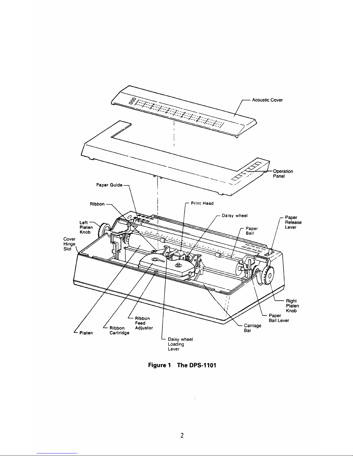
Paper Guide
I
~/
Print Head
Daisy wheel
Loading
Lever
figure
1
D
PS-1101
The
2
Acoustic Cover
operation
Panel
Right
Platen
Knob
Page 9
CHAPTER 1
HOW
TO UNPACK, SET UP,
AND
USE THE PRINTER
STEP-BY-STEP INSTRUCTIONS
1.
Inspect
the
shipping
carton
for
damage.
If
you
find
any external damage
to
the shipping carton and suspect that
the
printer
may
have been affected, contact
your
dealer.
2.
Remove
the
plastic
wrapping
from
the
printer.
3.
Remove
the
styrofoam
blocks
located
inside
the
printer.
The block on
the
left contains
the
following
items:
power
cord, interface
cable, daisy wheel,
ribbon
cartridge, and rubber carriage stopper. If
anything
is missing, contact
your
dealer.
4.
Remove
the
sheet
of
paper
wrapped
around
the
platen
(see Figure
fl.
5.
Remove
the
tape
from
the
carriage
bar
(see Figure
fl.
3
Page 10
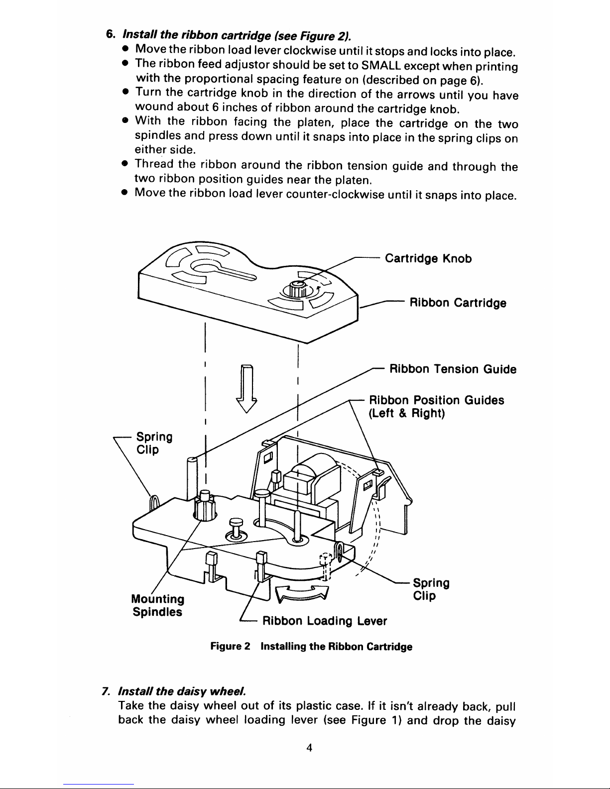
6.
Install
the
ribbon
cartridge
(see Figure 2).
•
Move
the
ribbon
load lever clockwise until
it
stops and locks
into
place.
• The ribbon feed adjustor should be set
to
SMALL except
when
printing
with
the
proportional
spacing feature on (described on page
6).
• Turn the cartridge knob in the direction
of
the
arrows
until
you
have
wound
about
6 inches
of
ribbon around the cartridge knob.
•
With
the
ribbon
facing the platen, place the cartridge on the
two
spindles and press
down
until
it
snaps into place in the spring clips on
either
side.
• Thread the ribbon
around
the
ribbon
tension
guide
and
through
the
two
ribbon position guides near the platen.
•
Move
the ribbon load lever counter-clockwise until
it
snaps
into
place.
Cartridge Knob
Ribbon Tension Guide
Ribbon Position Guides
(Left & Right)
Ribbon Loading Lever
Spring
Clip
Figure 2 Installing
the
Ribbon Cartridge
7.
Install
the
daisy
wheel.
Take the daisy wheel
out
of
its plastic case. If
it
isn't
already back, pull
back the
daisy
wheel
loading
lever (see Figure
1)
and
drop
the
daisy
4
Page 11

wheel into the space that opened up when you pulled back the lever.
Make sure the raised letters on the daisy wheel are facing the platen,
then push the loading lever forward
to
lock in the wheel.
's.
Attach
the
acoustic cover.
Remove the plastic wrapping. Hold the cover perpendicular and slide it
onto
the
two
little pegs on either side
of
the cover hinge slot on the
front/bottom
of
the opening
of
the printer (see Figure
1).
9.
Connect
the
power
cord.
Check the ON/OFF switch on the back
of
the printer (see Figure
3)
and
make sure the printer is
OFF
before you connect anything. Plug the
power
cord
into
the back
of
the printer under the ON/OFF switch and plug
the other end into a grounded (3-prong) outlet. Don't turn the
power
on
yet.
Interface Cable Connectors
Figure 3 Back Panel
10. Connect
the
interface cable.
Power Cord Connector
Power Switch
Make sure
your
computer (and disk drive
or
any other peripherals)
is
turned off. Both ends
of
the interface cable are identical so it doesn't
matter which end you plug into the printer. It also doesn't matter which
serial port
that
you plug the cable into (see Figure
3).
If you have a disk
drive hooked up
to
your
computer, connect the printer interface cable to
the drive. Otherwise, plug the cable into the computer.
11.
Insert
paper.
You can use continuous feed
or
single sheets. Either way, insert the
paper just
as
you
would
for
a typewriter. First line up the paper guide
(see Figure
1)
with
the
first
white
mark on the left end
of
the ruler. Then
pull back the paper bail lever and insert the paper in the slot behind the
ruler. Use the platen knob
to
roll the paper into position. If the paper
comes up crooked, pull back the paper release lever and straighten the
paper. Then close the paper release lever and push the paper bail into
place.
5
Page 12
12. Turn on the
power
and run the selftest.
You can
turn
on
the
power
to
peripherals in any order you want, but
always
turn
on
power
to
the computer last. If you
want
the printer
to
go
through
its selftest, insert a sheet
of
paper sideways (because the printer
prints an extra long line
of
characters
as
part
of
the selftest) then press
the
Form
Feed
button
while
turning on the power. The selftest checks the
Buffer RAM, operation
of
the print mechanism, and print quality.
On
the
first
line, the printer prints: Selftest. On the second line it should print:
RAM ok.
If
it
doesn't,
or
if it
prints RAM BAD, you've
got
a problem and
should contact
your
dealer. After those first
two
lines, the printer begins
printing
characters on one long line and then just continues
to
repeat
that
line. To stop the selftest, and ready the printer
for
use,
turn
the
power
switch
OFF
and then back
ON
again (anytime you turn the power
on and off,
wait
a couple
of
seconds after you
turn
it
off
before you turn
it
on again so
that
the printer has time
to
reset).
OPERATION
PANEL
As
you
can
see
in Figure
1,
the operation panel
is
located on the top, right
hand side
of
the printer. The panel contains the
following:
Spacing selection
buttons-Allow
you
to
choose the number
of
characters
per inch that the printer
will
print. The choices are
10, 12,
and
15.
You
can
also choose proportional spacing (ps), which spaces characters according
to
their
size. That means the printer gives
more
space
for
wider
letters such
as
"m"
and less space
for
letters such
as
"i".
Power
indicator-Lights
up when the printer is ON.
Alert
indicator-Lights
up when the ribbon
or
paper has run
out
and when
you stop the printer
with
the Pause/Clear button. It blinks when
an
error
occurs
(if
an
error does occur, refer
to
the troubleshooting guide later in
this
chapter).
Pause/Clear
button-Stops
and restarts the printer
while
it
is printing. Also
turns
off
the alert indicator after you've corrected the problem that caused
it
to
light
up.
Form
Feed
button-Advances
the paper through the printer until
it
reaches
"top
of
form,"
which is automatically set by the printer each
time
it's
turned on. The
"form
length"
is set at
11
inches. So,
if
you're at the
"top
of
form"
and press the Form
Feed
button, the printer advances the paper
11
inches. However,
if
the printer has printed, say
for
instance, 5 vertical
inches
worth
of
text, and you press the Form
Feed
button, the
printer
will
advance the paper 6 inches. You must first press the Pause/Clear button
for
the
Form
Feed
button
to
work. Then, after you use the Form Feed button,
press the Pause/Clear button
to
clear the printer
for
printing.
6
Page 13
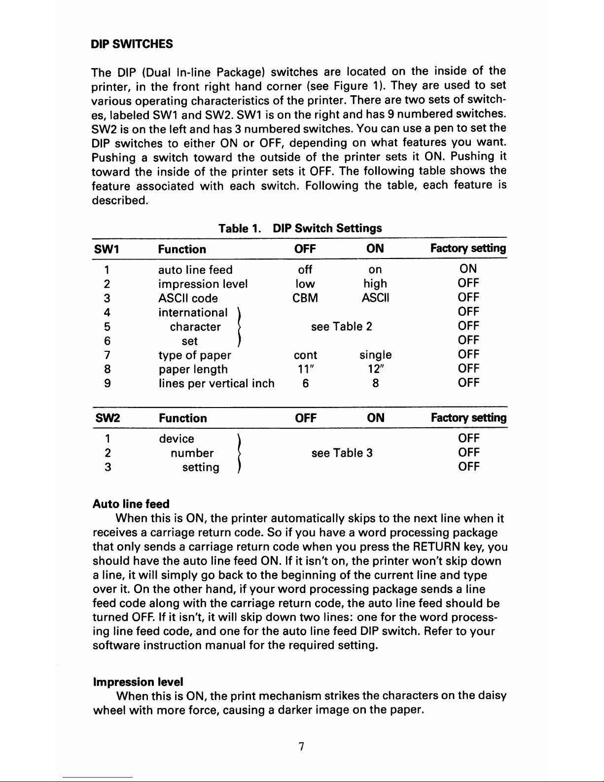
DIP SWITCHES
The
DIP
(Dual In-line Package) switches are located on the inside
of
the
printer, in the
front
right
hand corner
(see
Figure
1).
They are used
to
set
various operating characteristics
of
the printer. There are
two
sets
of
switch-
es,
labeled
SW1
and SW2.
SW1
is on the right and has 9 numbered switches.
SW2 is on the left and has 3 numbered switches. You
can
use a pen
to
set the
DIP
switches to either
ON
or
OFF,
depending on
what
features you want.
Pushing a switch
toward
the outside
of
the printer sets it
ON.
Pushing it
toward
the inside
of
the printer sets it
OFF.
The following table shows the
feature associated
with
each switch. Following the table, each feature is
described.
Table 1.
DIP Switch Settings
SW1 Function
OFF
ON
Factory setting
1
auto line feed
off
on
ON
2 impression level
low
high
OFF
3 ASCII code
CBM
ASCII
OFF
4
;nto.oot;onol I
OFF
5 character
see
Table 2
OFF
6
set
OFF
7
type
of
paper
cont
single
OFF
8
paper length
11"
12"
OFF
9 lines per vertical inch
6
8
OFF
SW2
Function
OFF
ON
Factory
setting
1
device
OFF
2
number
see
Table 3
OFF
3 setting
OFF
Auto line feed
When this is ON, the printer automatically skips
to
the next line when
it
receives a carriage return code. So
if
you have a
word
processing package
that
only
sends a carriage return code when you press the
RETURN
key,
you
should have the auto line feed ON. If it isn't on, the printer
won't
skip
down
a line, it
will
simply
go back
to
the beginning
of
the current line and type
over it.
On
the other hand,
if
your
word
processing package sends a line
feed code along
with
the carriage return code, the auto line feed should be
turned
OFF.
If
it
isn't, it
will
skip
down
two
lines: one
for
the
word
process-
ing line feed code, and one
for
the auto line feed
DIP
switch. Refer
to
your
software instruction manual
for
the required setting.
Impression level
When this is ON, the
print
mechanism strikes the characters on the daisy
wheel
with
more force, causing a darker image on the paper.
7
Page 14

ASCII code
Chooses between ASCII and CBM character sets (see Appendix
B).
Your
software package instructions should tell you which character set you should
use.
International character sets
Chooses
from
among the character sets
of
several countries (see
Appendix D
for
a list
of
special daisy wheels needed
for
the various character
sets). The
following
table lists the
DIP
switch settings needed for each
country's character set.
Table
2.
Switch
Settings
for
International Character Sets
Country
Switch
5
Switch
6
Switch
7
USA
off off
off
France
off
off
on
Germany
off
on
off
England
off
on
on
Denmark
on
off
off
Sweden
on
off
on
Italy on on
off
Spain on on
on
Type
of
paper
Chooses between continuous-feed and single sheet paper. When set
for
single sheet (ON), the printer automatically stops printing at the end
of
a
page. Remove
that
page, insert another, and press the Pause/Clear button to
continue printing again.
Paper
length
Set this switch
to
correspond to the length
(11"
or
12")
of
the sheets
of
paper you are using (whether a single sheet
or
a sheet
of
continuous-feed
paper).
Vertical
line
spacing
Chooses between 6 lines per vertical inch
(OFF)
and 8 lines per vertical
inch (ON).
Device
number
Allows
you
to
change the device number
of
the printer. When you type in
a
command
on the computer, you have
to
include a device
number
so that
the
computer
knows where
to
send the command (to the disk drive,
to
the
printer, etc.). The normal device number
for
a printer is
4.
Usually, there is no
reason
to
change the device number. But say,
for
instance, you have
two
printers connected
to
your
computer. You
would
then need
to
change the
device
number
of
one
of
them so that the computer
would
know which was
which. The
following
table lists the possible device numbers and indicates
how
to
set the switches
for
each.
8
Page 15
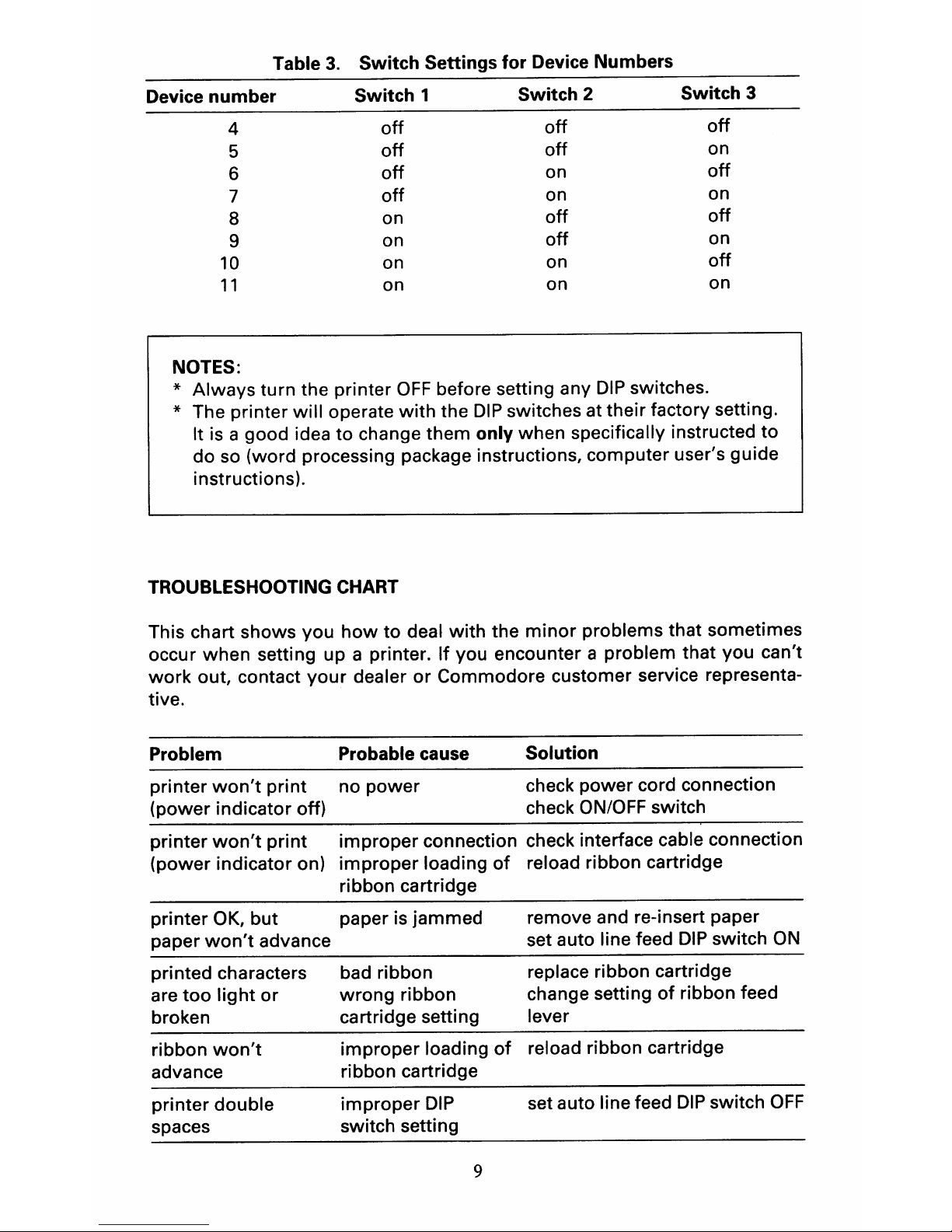
Table
3.
Switch
Settings
for
Device Numbers
Device
number
Switch
1
Switch
2
Switch
3
4
off
off
off
5
off
off
on
6
off
on
off
7
off
on
on
8
on
off
off
9
on
off
on
10
on on
off
11
on on
on
NOTES:
* Always
turn
the printer
OFF
before setting any
DIP
switches.
* The printer
will
operate
with
the
DIP
switches at their factory setting.
It is a good idea
to
change them
only
when specifically instructed
to
do so (word processing package instructions, computer user's guide
instructions).
TROUBLESHOOTING CHART
This chart shows you
how
to
deal
with
the
minor
problems that sometimes
occur when setting up a printer.
If
you encounter a problem that you can't
work
out, contact
your
dealer
or
Commodore customer service representa-
tive.
Problem Probable cause
printer
won't
print
no power
(power indicator off)
Solution
check power cord connection
check ON/OFF switch
printer
won't
print
improper connection check interface cable connection
(power indicator on)
improper
loading
of
reload ribbon cartridge
ribbon cartridge
printer OK,
but
paper is jammed
paper
won't
advance
printed characters bad ribbon
are
too
light
or wrong ribbon
broken cartridge setting
ribbon
won't
improper
loading
of
advance ribbon cartridge
printer double
improper
DIP
spaces switch setting
9
remove and re-insert paper
set auto line feed
DIP
switch
ON
replace ribbon cartridge
change setting
of
ribbon feed
lever
reload ribbon cartridge
set auto line feed
DIP
switch
OFF
Page 16

SAFETY
TIPS
1.
Wait at least
two
seconds
to
turn
on the
power
after it has been turned
off
so
that
the printer can initialize properly.
2.
Don't connect
or
disconnect the inter-face cable
if
either the printer
or
the
computer
is on.
3.
Keep
your
fingers, jewelry, and clothing clear
of
moving parts.
4.
Don't place the printer in direct sunlight.
5.
Turn the printer
off
immediately
if
an
object falls into the printer. Then
remove the object.
6.
Don't
move the print head manually.
7.
Avoid extremes in temperature and
humidity
in the operating environ-
ment
of
the printer (temperatures between
41
and 95 degrees Fahrenheit
and
humidity
between
30
and 85 percent are acceptable).
8.
Don't touch the carriage
rail-
it
can
get hot.
\0
Page 17
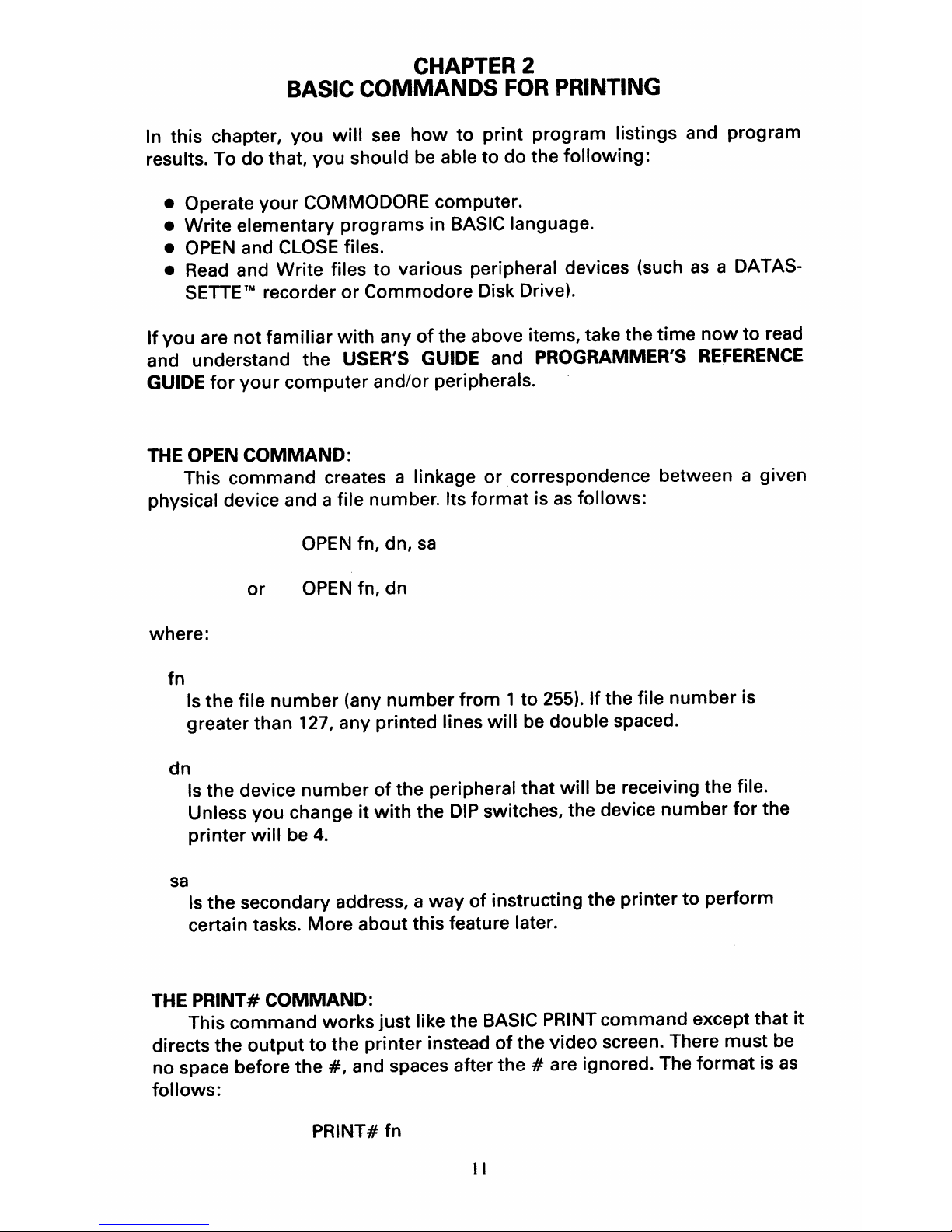
CHAPTER 2
BASIC
COMMANDS
FOR
PRINTING
In
this
chapter,
you
will
see
how
to
print
program listings and program
results. To
do
that, you should
be
able
to
do the
following:
• Operate
your
COMMODORE computer.
•
Write
elementary programs in BASIC language.
•
OPEN
and
CLOSE
files.
• Read and Write files
to
various peripheral devices (such
as
a DATAS-
SETTE'" recorder
or
Commodore Disk Drive).
If
you
are
not
familiar
with
any
of
the above items, take the
time
now
to
read
and understand the USER'S GUIDE and PROGRAMMER'S
REFERENCE
GUIDE
for
your
computer
and/or peripherals.
THE
OPEN COMMAND:
This command creates a linkage
or
correspondence between a given
physical device and a file number. Its
format
is
as
follows:
OPEN
fn, dn,
sa
or
OPEN
fn,
dn
where:
fn
Is
the
file
number
(any
number
from 1 to
255).
If
the file
number
is
greater than
127, any printed lines
will
be
double spaced.
dn
sa
Is
the device
number
of
the peripheral
that
will
be
receiving the file.
Unless you change
it
with
the
DIP
switches, the device number
for
the
printer
will
be 4.
Is
the secondary address, a
way
of
instructing the printer
to
perform
certain tasks. More about this feature later.
THE
PRINT# COMMAND:
This command works
just
like the BASIC PRINT
command
except
that
it
directs the
output
to
the printer instead
of
the video screen. There
must
be
no space before the
#,
and spaces after
the
# are ignored. The
format
is
as
follows:
PRINT# fn
II
Page 18
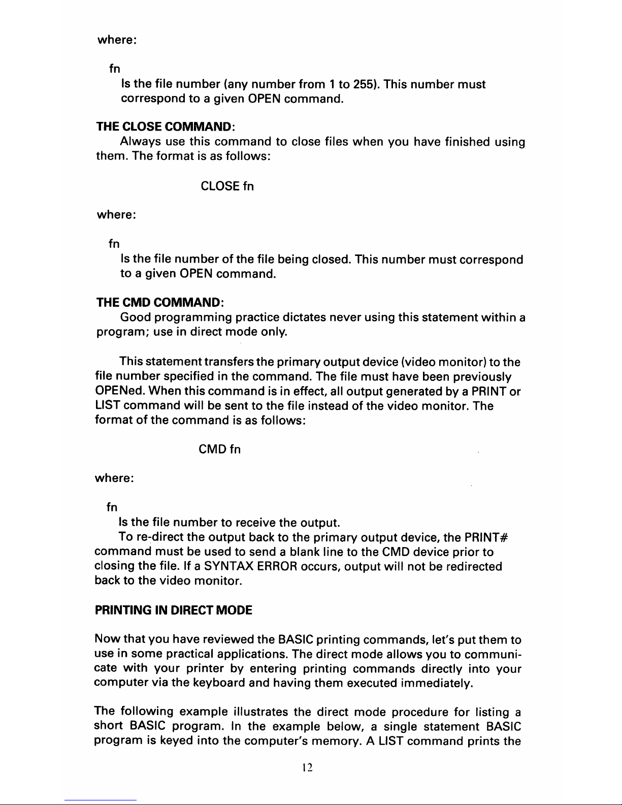
where:
fn
Is
the file
number
(any
number
from 1 to
255). This number
must
correspond
to
a given
OPEN
command.
THE
CLOSE
COMMAND:
Always use this command
to
close files when you have finished using
them. The
format
is
as
follows:
CLOSE
fn
where:
fn
Is
the file
number
of
the file being closed. This
number
must correspond
to
a given
OPEN
command.
THE
CMD
COMMAND:
Good
programming
practice dictates never using this statement
within
a
program; use in direct mode only.
This statement transfers the primary
output
device (video monitor)
to
the
file
number
specified in the command. The file must have been previously
OPENed. When
this
command is in effect, all output generated by a PRINT or
LIST command
will
be sent
to
the file instead
of
the video monitor. The
format
of
the
command
is
as
follows:
CMDfn
where:
fn
Is
the file
number
to
receive the output.
To
re~direct
the
output
back
to
the primary
output
device, the PRINT#
command
must
be used to send a blank line to the CMD device prior
to
closing the file. If a SYNTAX
ERROR
occurs, output
will
not
be
redirected
back
to
the video monitor.
PRINTING
IN
DIRECT
MODE
Now
that
you have reviewed the BASIC printing commands, let's
put
them
to
use in some practical applications. The direct mode allows you
to
communi-
cate
with
your
printer by entering printing commands directly into your
computer
via the keyboard and having them executed immediately.
The
following
example illustrates the direct mode procedure
for
listing a
short BASIC program.
In
the example below, a single statement BASIC
program is keyed
into
the computer's memory. A LIST command prints the
12
Page 19
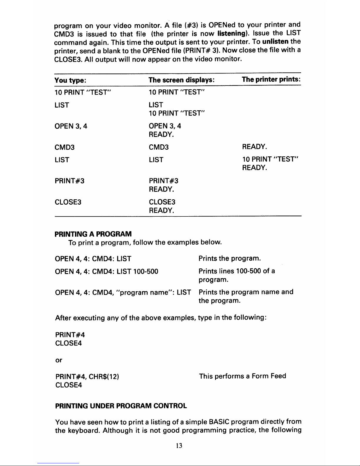
program on your video monitor. A file (#3) is
OPENed
to your printer and
CMD3 is issued
to
that file (the printer
is
now
listening). Issue the LIST
command again. This
time
the output is sent to your printer. To unlisten the
printer, send a blank to the OPENed file (PRINT#
3).
Now
close the file
with
a
CLOSE3.
All output
will
now
appear on the video monitor.
You
type:
10
PRINT "TEST"
LIST
OPEN
3,4
CMD3
LIST
PRINT#3
CLOSE3
PRINTING A PROGRAM
The screen displays:
10
PRINT "TEST"
LIST
10
PRINT "TEST"
OPEN
3,4
READY.
CMD3
LIST
PRINT#3
READY.
CLOSE3
READY.
The printer prints:
READY.
10
PRINT "TEST"
READY.
To
print
a program,
follow
the examples below.
OPEN
4,
4: CMD4: LIST
OPEN
4,
4: CMD4: LIST 100-500
Prints the program.
Prints lines 100-500
of
a
program.
OPEN
4, 4: CMD4,
"program
name":
LIST Prints the program name and
the program.
After executing any
of
the above examples, type in the following:
PRINT#4
CLOSE4
or
PRINT#4,
CHR$(12)
CLOSE4
PRINTING UNDER PROGRAM CONTROL
This performs a Form
Feed
You have seen
how
to print a listing
of
a simple
BASIC
program directly from
the keyboard. Although
it
is
not
good programming practice, the following
13
Page 20
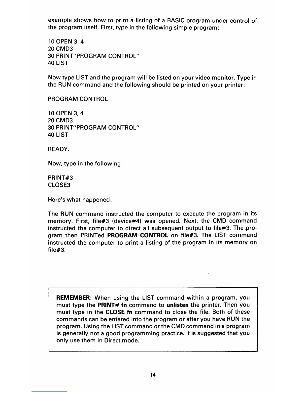
example shows
how
to
print a listing
of
a BASIC program under control
of
the program itself. First, type in the
following
simple program:
10
OPEN
3,
4
20
CMD3
30
PRINT"PROGRAM CONTROL"
40 LIST
Now
type LIST and the program
will
be
listed on
your
video monitor. Type in
the RUN command and the
following
should be printed on
your
printer:
PROGRAM CONTROL
10
OPEN
3,4
20
CMD3
30 PRINT"PROGRAM CONTROL"
40
LIST
READY.
Now, type in the
following:
PRINT#3
CLOSE3
Here's
what
happened:
The RUN command instructed the computer
to
execute the program in its
memory. First,
file#3
(device#4) was opened. Next, the CMD command
instructed the
computer
to
direct all subsequent
output
to
file#3. The .pro-
gram
then PRINTed PROGRAM CONTROL on file#3. The LIST command
instructed the
computer
to
print
a listing
of
the program in its
memory
on
file#3.
REMEMBER: When using the LIST command
within
a program,
you
must
type the PRINT# fn command
to
unlisten the printer. Then
you
must
type in the CLOSE fn command
to
close the file. Both
of
these
commands
can be entered
into
the program
or
after
you
have RUN the
program. Using the LIST command
or
the CMD command in a program
is generally
not a good
programming
practice. It is suggested that
you
only
use
them
in Direct mode.
14
Page 21
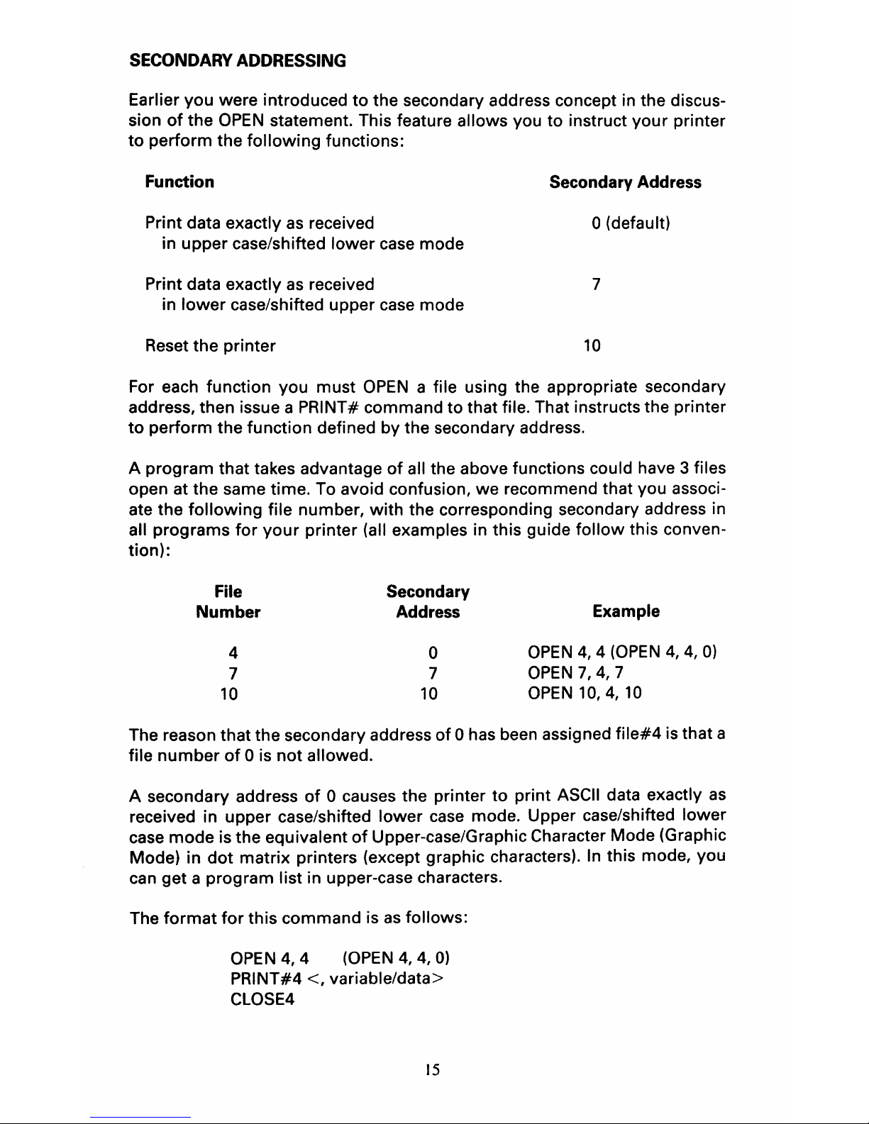
SECONDARY ADDRESSING
Earlier you were introduced
to
the secondary address concept in the discus-
sion
of
the
OPEN
statement. This feature allows you to instruct your printer
to
perform the
following
functions:
Function Secondary Address
Print data exactly as received
o (default)
in upper case/shifted lower case mode
Print data exactly
as
received 7
in
lower
case/shifted upper case mode
Reset the printer
10
For each function you must
OPEN
a file using the appropriate secondary
address, then issue a PRINT# command to that file. That instructs the printer
to
perform the function defined by the secondary address.
A program that takes advantage
of
all the above functions could have 3 files
open at the same time. To avoid confusion,
we
recommend that you associ-
ate the
following
file number,
with
the corresponding secondary address in
all programs
for
your
printer (all examples in this guide
follow
this conven-
tion):
File Secondary
Number
Address
Example
4 0
OPEN
4, 4 (OPEN
4,4,0)
7
7
OPEN
7,4,7
10
10
OPEN
10,4,10
The reason that the secondary address
of
0 has been assigned
file#4
is that a
file
number
of
0 is
not
allowed.
A secondary address
of
0 causes the printer
to
print
ASCII
data exactly
as
received in upper case/shifted
lower
case mode. Upper case/shifted lower
case mode is the equivalent
of
Upper-case/Graphic Character Mode (Graphic
Mode) in
dot
matrix printers (except graphic characters).
In
this mode, you
can get a program list in upper-case characters.
The
format
for
this command is
as
follows:
OPEN
4,
4
(OPEN
4,
4,
0)
PRINT#4 <, variable/data>
CLOSE4
15
Page 22

In
global upper case/shifted
lower
case
mode, you
can
print in local lower
case/shifted upper case mode. When you want to print data in local
lower
case/shifted upper case, you should use the Cursor Down Code[CHR$(17)].
Conversely, when you
want
to
print data in local upper case/shifted lower
case, you should use the Cursor Up Code [CHR$(145)).
A secondary address
of
7 allows the printer
to
print data exactly
as
received
in
lower
case/shifted upper case mode. The SYNTAX
of
the secondary ad-
dressing
of 7 is
compatible
with
that of all serial printers.
The
format
for
this command is
as
follows:
or
OPEN
4,
4,
7
PRINT#4
<, variable/data>
CLOSE4
OPEN
7,4,7
PRINT#7 <, variable/data>
CLOSE7
16
Page 23
In global
lower
case/shifted upper case mode, you can print in local upper
case/shifted
lower
case mode. When you
want
to
print data in local upper
case/shifted
lower
case, you should use the Cursor Up Code [CHR$(145)].
Conversely, when you
want
to
print
data in local lower case/shifted upper
case,
you
should use the Cursor Down Code [CHR$(17)].
A secondary address
of
10
resets the printer.
The
format
for
this
command is
as
follows:
OPEN
10,4,
10
PRINT#10
CLOSE10
17
Page 24

Page 25
CHAPTER
THREE
CONTROL CODES
ASCII CODES
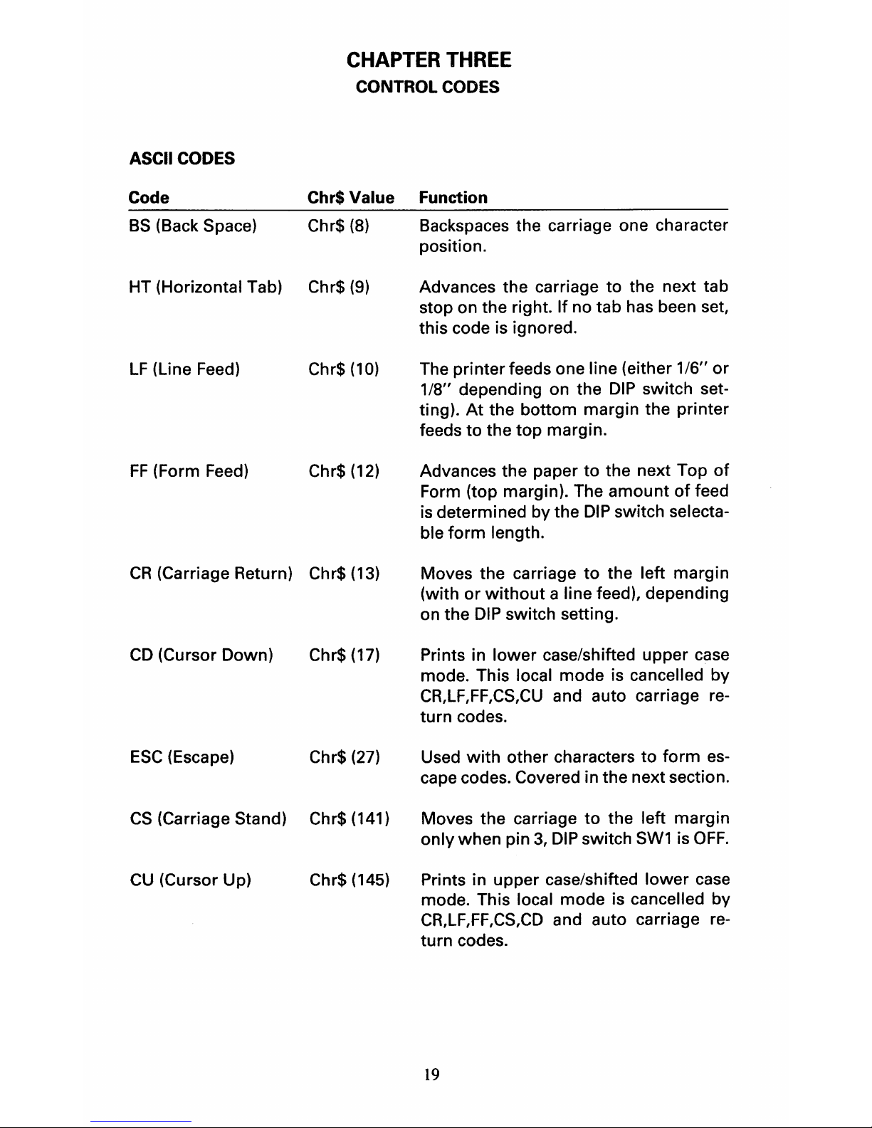
Code Chr$ Value Function
BS
(Back Space) Chr$
(8)
Backspaces the carriage one character
position.
HT (Horizontal Tab) Chr$
(9)
Advances the carriage
to
the next tab
stop on the right.
If
no tab has been set,
this code is ignored.
LF
(Line Feed) Chr$
(10)
The printer feeds one line (either
116"
or
1/8" depending on the
DIP
switch setting). At the bottom margin the printer
feeds
to
the top margin.
FF
(Form Feed) Chr$
(12)
Advances the paper
to
the next Top
of
Form (top margin). The
amount
of
feed
is
determined by the
DIP
switch selecta-
ble
form
length.
CR
(Carriage Return) Chr$
(13)
CD
(Cursor Down)
Chr$
(17)
ESC
(Escape) Chr$ (27)
CS
(Carriage Stand) Chr$ (141)
CU
(Cursor Up) Chr$ (145)
Moves the carriage
to
the left margin
(with or
without
a line feed), depending
on the
DIP
switch setting.
Prints in lower case/shifted upper case
mode. This local mode is cancelled by
CR,LF,FF,CS,CU
and auto carriage re-
turn codes.
Used
with
other characters
to
form
es-
cape codes. Covered in the next section.
Moves the carriage
to
the left margin
only when pin
3,
DIP
switch
SW1
is
OFF.
Prints in upper case/shifted lower case
mode. This local mode is cancelled by
CR,LF,FF,CS,CD
and auto carriage re-
turn codes.
19
Page 26
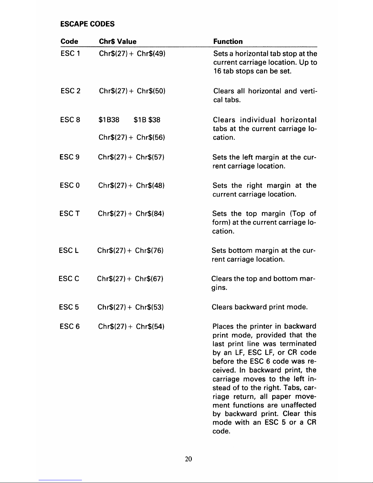
ESCAPE
CODES
Code
Chr$ Value
ESC
1 Chr$(27) + Chr$(49)
ESC2
Chr$(27)
+ Chr$(50)
ESC
8 $1838 $18 $38
Chr$(27) + Chr$(56)
ESC9
Chr$(27)
+ Chr$(57)
ESCO
Chr$(27) + Chr$(48)
ESCT
Chr$(27) + Chr$(84)
ESC
L
Chr$(27)
+ Chr$(76)
ESCC
Chr$(27)
+ Chr$(67)
ESC
5
Chr$(27)
+ Chr$(53)
ESC6 Chr$(27)
+ Chr$(54)
20
Function
Sets a horizontal tab stop at the
current carriage location.
Up
to
16
tab stops can be set.
Clears all horizontal and vertical tabs.
Clears
individual
horizontal
tabs at the current carriage location.
Sets the left margin at the cur-
rent carriage location.
Sets the right margin at the
current carriage location.
Sets the
top
margin (Top
of
form) at the current carriage location.
Sets bottom margin at the cur-
rent carriage location.
Clears the
top
and
bottom
mar-
gins.
Clears backward print mode.
Places the printer in backward
print mode, provided that the
last
print
line was terminated
by
an
LF,
ESC
LF,
or
CR
code
before the
ESC
6 code was received. In backward print, the
carriage moves
to
the left in-
stead
of
to
the right. Tabs, carriage return, all paper movement functions are unaffected
by backward print. Clear this
mode
with
an
ESC 5 or a CR
code.
Page 27

Code
Chr$Value
ESC
LF
Chr$(27l+ Chr$(10)
ESCD Chr$(27)
+ Chr$(68)
ESCU
Chr$(27) + Chr$(85)
ESC
US n Chr$(27) + Chr$(31) + Chr$(n)
ESC
RS
n Chr$(27) + Chr$(30) + Chr$(n)
ESC
FF
n Chr$(27) + Chr$ (12)+ Chr$(n)
21
Function
Causes a negative line feed
(the printer feeds in the oppo-
site direction
of
normal line
feed so that it prints on the line
above the line just printed).
Causes a
negative
half-line
feed
(1/2
VMI).
If
the VMI (see
next section) is set by some
odd number in terms
of
multi-
ples
of
1/48 inch, the
amount
of
movement is determined on a
round-off basis.
Causes a half-line feed. If the
VMI
is
set by some odd num-
ber in
terms
of
multiples
of
1/48 inch, the amount
of
movement determined on a roundoff
basis.
Alters the standard HMI, which
determines
how
the carriage
spaces after printing a charac-
ter. The
"n"
in the code corre-
sponds
to
the "decimal data in
the
following:
HMI = (decimal
data -
1)
x 1/120" (the maxi-
mum
decimal data is 127).
Alters the standard VMI, which
determines
the
paper
feed
amount. The
"n"
in the code
corresponds
to
the "decimal
data in the
foliowing:VMI
=
(decimal data -
1) x 1148"
The
maximum
decimal data is 127).
Sets the
number
of
lines per
page by using decimal data,
which corresponds
to
the number
of
lines per page. The mini-
mum
number
of
lines per page
is 1,
the
maximum
is 126.
Length = decimal data x VMI
inches
Page 28

Code Chr$ Value
Function
ESCS
Chr$+
Chr$(83) Sets HMI
to
10
CPI.
ESC
HT n Chr$(27) + Chr$(9) + Chr$(n) Positions the carriage at any
of
the
fi
rst
128
print
positions
without
setting any tabs. The
"n"
is
the decimal data
that
re-
presents
the
desired
posi-
tion.The
left-most
position is
1.
Horizontal position = (decimal
data -
1)
x HMI
ESC
VT n Chr$(27) + Chr$(11) + Chr$(n) Positions the carriage on any
of
128 possible lines on
the
page.
The
un"
is the decimal data
that
represents
the
desired
line. The
top
line
of
the page is
1.
ESCY
Chr$(27) + Chr$(89)
ESC
Z Chr$(27) + Chr$(90)
ESC
H
Chr$(27) + Chr$(72)
ESC
I
Chr$(27) + Chr$(73)
ESCJ
Chr$(27) + Chr$(74)
ESCK
Chr$(27) + Chr$(75)
ESC
CR
P Chr$(27) + Chr$(13) + Chr$(80)
ESC
/
Chr$(27) + Chr$(255)
(CBM ASCII mode)
ESC,
Chr$(27) + Chr$(92)
(Standard ASCII mode)
22
Vertical Position = (decimal
data-1)xVMI.
If the vertical position is be-
yond
the
bottom
margin
and
before the
top
margin, the code
is ignored.
Prints symbol
1.
Prints
symbol
2.
Prints symbol
3.
Prints
symbol
4.
Prints
symbol
5.
Prints
symbol
6.
Resets the printer
to
its initial
power-up state.
Auto
bi-directional
printing
ON.
Auto
bi-directional
printing
OFF.
Page 29

Code
Chr$
Value
ESC
P
Chr$(27) + Chr$(80)
ESCQ Chr$(27) + Chr$(81)
ESC
DC1
n Chr$(27)+ Chr$(17)+ Chr$(n)
23
Function
Proportional spacing
(PS)
ON.
PS
unit values represent one-
half the
width
required by a
proportionally-spaced charac-
ter. The letter
"A"
for
example
has a
PS
value
of
7,
which is
one-half the 14/120" spacing
an
"A"
requires.
Carriage
movement
is
calculated
by
adding the
PS
unit values
of
the characters to be printed.
Thus,
if
the carriage moves
10/120" after printing
"A"
and
before printing
"i"
it's because
that's the sum
of
the
PS
unit
values
of
the
"i"
(3)
and
"A"
(7).
Cancels proportional spacing
and sets the printer to
10
char-
acters per inch.
Offset selection
For proportional space printing, to add
or
subtract a con-
stant to each value
of
the table,
the
sequence
ESC
DC1
n
should be used. The value
of
"byte"
is added to each value
of
the table
or
HMI
if it
is con-
trolling size,
as
well
as
to the
space character. This continues
until another
ESC
DC1 n (n
=
byte) sequence is received,
or
until offset is cleared by a carriage return
or
the
ESCX.
"n"
is
as
follows:
Bits 0-5
=
Size
of
offset
Bit 6
= Sign
of
offset
(1
= negative)
If the resulting character size
is
zero, no carriage
movement
will occur.
Page 30

Code
ESC
E
ESC
R
ESCO
ESCW
ESC&
Chr$ Value
Chr$(27)
+ Chr$(69)
Chr$(27)
+ Chr$(82)
Chr$(27)
+ Chr$(79)
Chr$(27)
+ Chr$(87)
Chr$(27)
+ Chr$(38)
Function
Auto underline
ON.
Auto underline
OFF.
Bold print ON.
This mode is cancelled by a
CR
code.
Shadow print ON.
In
shadow
print,
the
printer
prints a character twice
with
a
carriage
movement
of
1/20"
between the two. This
mode
is
cancelled by a
CR
code.
Bold/Shadow Print Mode
OFF
Note: The auto underline, bold
print
and shadow
print
are
mutually
exclu-
sive. That is,
only
one
of
them can be used at a time.
ESC%
Chr$(27)
+ Chr$(37)
ESC
N
Chr$(27)
+ Chr$(78)
ESC
X
Chr$(27)
+ Chr$(88)
DEFINITIONS
Increases carriage settling time
to
50
msec. That provides more
time
for
mechanical vibration
to
subside before printing begins. That improves print quality,
with
the least sacrifice
of
print time.
Cancels the increased carriage
settling
time
mode.
Cancels all
of
the
following
modes:
auto underline
bold
print
shadow print
offset selection
The
following
are definitions
of
some terms used
in
the previous sections.
HMI (Horizontal Motion Index)
The
amount
of
carriage
movement
after a character is printed. 1
unit
is
11120"
and 0
-125
units can be designated.
VMI
(Vertical Motion Index)
The
amount
of
line feed between printed lines. One
unit
is 1/48" and
0-
125 units can be designated.
24
Page 31

Absolute Horizontal Position
The horizontal distance
from
the current position to the next. One
unit
is
1/120" and 0 - 1312 units can
be
designated.
Absolute Vertical Position
The distance
of
the paper feed
from
the current position to the next line.
One
unit
of
this movement
is
1/48" and 0 - 15,750 units
can
be
designated.
Print position
All the possible printing character numbers per line when characters are
printed by the indicated HMI. Horizontal print position
= HMI +
1.
The
printing
number
of
characters is 110 when they are printed when HMI =
12
and the Horizontal Position is 1308.
Line
Number
The
number
of
lines when the paper feed
is
made by the designated VMI.
Vertical line
number
= VMI + 1
The
number
of
lines
is
66,
when a new line is made
with
VMI = 8 and the
Horizontal Position is
520.
Lines Per Page
The actual
number
of
print lines per page
of
paper. Lines per page can
be
designated
to
any
number
from
1 through 126.
EXAMPLE PROGRAM
We've included the
following
program
as
an
example
of
how
to
incorporate
some
of
the previously covered control codes into
your
own
BASIC pro-
grams.
100
REM
THIS
PROGRAM
DEMONSTRATES
HOW
TO
USE
CONTROL
& ESCAPE CODES.
110
ESC$=CHR$(27)
:REM
CHR$(27)
IS
THE
ESCAPE CHARACTER.
1200PEN7,4,7
:REM
OPEN
LOWER
CASE PRINTER CHANNEL.
130
PRINT#7,"THIS
LINE
IS
PRINTED UNENHANCED."
140
REM
USE
TABLE
OF
CONTROL
CODES
TO
FIND NECESSARY VALUES.
150
PRINT#7,CHR$(27)+CHR$(79);
:REM
SEND
ESCAPE +
BOLD
PRINT CODE.
160
PRINT#7,"THIS
LINE
IS
PRINTED
IN
BOLD
PRINT."
170
PRINT#7,CHR$(27)+CHR$(26)
:REM SEND ESCAPE +
BOLD
PRINT
OFF CODE.
180
PRINT#7,CHR$(27)+CHR$(87);
:REM
SEND
ESCAPE +
SHADOW
PRINT CODE.
190
PRINT#? , "THIS
LINE
IS
PRINTED
IN
SHADOW
PRINT."
200
PRINT#7,CHR$(27)+CHR$(26)
:REM
SEND
ESCAPE +
SHADOW
PRINT OFF CODE.
210
PRINT#7,CHR$(27)+CHR$(69);
:REM
SEND
ESCAPE +
UNDERSCORE
CODE.
220
PRINT#7,"THIS
LINE
IS
PRINTED
IN
AUTO
UNDERSCORE
MODE."
230
PRINT#7,CHR$(27)+CHR$(82)
:REM
SEND
ESCAPE +
UNDERSCORE
OFF CODE.
250
REM
THE
NEXT
PRINTED
LINE
IS
AN
EXAMPLE
OF
NEGATIVE
I.INE
FEED.
260
PRINT#7,"ARITHMETIC
DIVIDE
SIGN
IS : ::::
:::"
270
PRINT#7,CHR$(27)+CHR$(10);
:REM
SEND
ESCAPE + NEGATIVE LINE FEED.
280
PRINT#7,"
--------"
300
REM
SOME
CONTROL
CODES
SHOWN
IN
THE
TABLE
DO
NOT
NEED
ESCAPE CHARACTER.
310
PRINT#7,CHR$(12);
:REM SEND
FORM
FEED CHARACTER.
320
PRINT#?,
"THIS
IS
ON
PAGE
TWO."
350
REM
THE
NEXT
ESCAPE
EXAMPLE
REQUIRES 3
VALUES
ACCORDING
TO
THE
TABLE.
360
PRINT#7,CHR$(27)+CHR$(9)+CHR$(15);
:REM
ESCAPE HORIZ.
TAB
TO
COLUMN
15.
370
PRINT#7,"THIS
STARTS PRINTING
IN
COLUMN
15."
380
CLOSE7
390
REM
USE
THE
ABOVE
EXAMPLES
AS
A GUIDE
WHEN
WRITING
YOUR
OWN
PROGRAMS.
25
Page 32

Page 33

CHAPTER
4
DOWNLOAD
The Down Load feature enables a programmer to create his
own
print
character table. This allows
for
the use
of
non-standard and special print
wheels. It is basically a
"look-up"
table that specifies a particular print wheel
spoke, hammer energy, and proportional space unit to
be
printed
for
any
particular received character code.
Down load mode starts when
ESC
SO
DC2
is received, and ends when
DC4
is
received. Once the
down
load procedure has been completed, the down load
table is automatically selected. Down load is aborted when power is turned
off, when an error occurs,
or
when a remote reset
(ESC
CR
PI
is received.
NOTE:
If
you are using one
of
the daisy wheels described
in
Appendix
E,
there
is
no
need
to
Down Load the character table. The tables
for
those
wheels are in ROM. Select the appropriate table by setting the
DIP
SW1,
switches 4,
5,
and
6.
There are
two
variations
of
the down load procedure:
down
loading the table
by a single record, and
down
loading by multiple records.
r----------------------------------,
I I
I
Multiple
records I
!:~r~r~i
T
rt
ESC
SO
DC2
(Down
load start)
DC4
(Table load end)
~------------------------------------~
I I
I Single record I
I I
LJ
----~r
-
----
-----~r__L
27
Page 34

DOWN
LOAD RECORD FORMAT
The record consists of
the
following:
Format
lIS"
-
-------a)
111"
-------
b)
-------c)
----
--
-d)
-
-------
e)
--
_L.-
§--'I
1. Record Start Character
Function
Record start character
Record type character
Byte
count
(1
byte)
Load start address (2 byte)
Table data (2
byte
x 100 print characters
= 200 bytes)
Checksum
(1
byte)
Record start character
is
an
ASCII
"S",
Any data encountered before
the
"S"
will be ignored. Therefore any data before, after or between data records will
be
ignored and will
not
affect
the
down load process,
r----------------------------------------
I
I
I
I
Down
load process
(Multiple)
I
~f
DATA
:S:
r~
r-;;:~
-+--5
j
r---J,
v~--_/
I t I
~r-----1.
OAT
A
_~f-
ignore I
~
ESC
SO
DC2
Record start
28
Page 35

2.
Record
Type Character
Record type character must be an ASCII
"0"
or
"9"
will simply be ignored. Any
character other than a
"0",
"1"
or
"9"
is
detected as a down load error.
3. Byte Count
The byte
count
shows the number of total input bytes per 1 record.
The byte
count
shows the number
of
data bytes
to
follow, including the address
and checksum.
4.
Load
Address
The load address consists of 2 bytes.
It specifies
the
starting address
in
memory where
the
table data
is
to
be
loaded.
The block address allocated
to
this extends from HEX
0040
through 0107.
A load address outside this range
is
interpreted
as
a down load error.
The load address must be equal
to
two times the hex value of the first
ASCII character of the record. (excluding
ESC
H,
I,
J,
K)
table data
address
(HEX)
ASCII
start
Byte
Byte
0040
J
ESC
Y
0041
Byte
Byte
0042 J
21HEX
0043
Byte
Byte
0044J
22HEX
0045
:::r::o=
:=::::::
.::r:=
::=:::::
Byte
Byte
0104
]
ESCJ
0105
Byte
Byte
0106
]
ESC
K
0107
Byte
Byte
0108
]
$AO
0109
Byte
Byte
010AJ
$A1
010B
:::::::
::::::::=
.::~
::::::::
Byte
0156
$BF
end
Byte
0157
29
Page 36

Note: Symbol
Code
Address (HEX)
ESCY ASCII20HEX
0040-0041
ESCZ
ASCII 7FHEX
OOFE-OOFF
ESC
H
0100-0101
ESC
I
0102-0103
ESC
J
0104-0105
ESC
K 0106-0107
The load address of
the
first record
is
always HEX0040.
5. Table Data
The table data
is
shown in binary notation
as
follows:
Bit
7
6
5 4 3 2 0
1st Byte ....
P
H H H
Ps
Ps
Ps Ps
2nd Byte .... R S
S S
S
S S
S
P
1 Printable position
o Nonprinting position
H Hammer energy 0 - 7
Ps
...... Proportional space value 0 - 15
R ...... Always 0
S
......
Spoke position 0 -
99
All
of the 100 characters
in
the table data must be loaded. Otherwise,
is
inter-
preted as a down load error.
For any nonprinting print wheel positions, the
"P"
bit shown
in
the
1st byte
must be a
"0".
If
ASCII
code, which
is
equivalent
to
the print wheel position
loaded
at
p=O
is
input, the spacing volume will be the same as
the
space code.
Hammer energy consists of 8 levels from 0 through 7.
Proportional Space value can be chosen from the range of 0 - 15.
If
Ps
= 0, the carriage does not move.
Spoke position extends from 0 through 99. If any position outside this range
is
appointed, it
is
interpreted as a down load error.
When determining table data,
see
character
level
(APPENDIX
D)
6. Checksum
It
is
"2's"
complement of
the
sum
of
all
data bytes, starting with the byte count.
Therefore, when all the data bytes starting with the byte count are added together, and the checksum
is
then
added, the result must be zero.
No
end-around
carry
is
used when the check sum
is
calculated.
If
the checksum calculation results
in
a non-zero sum, it
is
interpreted as a down
load error.
30
Page 37

SAMPLE
PROGRAM
The following
is
a sample program
to
perform
"down
load". With this program,
"down
load" both
for
Standard ASCII mode and CBM ASCII mode
can
be
per-
formed.
1000
1010
1020
1030
1040
1050
1060
1070
1080
1090
1100
11
10
11
20
1130
1140
1150
1160
11
70
1180
1190
1200
1
210
1220
1230
1240
1250
1260
1270
1280
1290
1300
1310
1320
1330
1340
1350
1360
1370
1380
rem
rem
rem
rem
rem
rem
rem
rem
***********************************
-i(
",;
*
"Down
Load
Sample
Program
i'(
*
*
*
( c )
1984
~k
*
"Commodore
Japan
Limited
;I(
*
*
***********************************
dim
a(99),b(99),bl(191),b2(191)
esc$=chr$(27):cr$=chr$(13):lf$=chr$(10)
so$=chr$(14)
:d2$=chr$(18):d4$=chr$(20)
ht$=chr$(9)
:ff$=chr$(12)
open4,4
print4F4,esc$;cr$;"p"
:rem
remote
reset
print
chr$(l47)
print"
which
character
mode
do
you
select"
print
print"
print"
print
input
"
if
mode$="s"
if
mode$="c"
goto
1180
print:print
s =
standard
ascii
mode"
cbm
ascii
mode"
c
(sic)
clll";mode$
then
gosub
1290
:goto
1390
then
gosub
1340
:goto
1390
print"standard
ascii
mode
selected"
print:print"please
set
dip
sw
103
on"
return
print:print
print"cbm
ascii
mode
selected"
print:print"please
set
dip
sw
103
off"
return
31
Page 38

1390
print:print:print
1400
print"press
«return»
when
ready"
1410
geta$:ifa$=""then
1410
1420
if
asc(a$)<>13
then
1410
1430
1440
print1f4,"down
load
test";
1450
print
chr$(147);
1460
if
mode$="c"
then
gosub
1500
1470
if
mode$="s"
then
gosub
1550
1480
gotol600
1490
1500
print:ft4,"
(cbm
ascii
mode)":printlI4
1510
print:print
1520
print"
cbm
ascii
mode"
1530
return
1540
1550
print1f4,"
(standard
ascii
mode)":printtl4
1560
1 5 7 0
1580
1590
1600
1 6 1 0
1620
1630
1640
1650
1660
1670
1680
print:print
print
"
return
standard
ascii
mode"
rem
***********************************
rem
>'<
down
load
procedure
body
*
rem
***********************************
table=100
:rem
table(all)
for
i=O
to
table-l
read
s,p,h,ps
print
chr$(19)ji
a(i)=(p*128+h*16+ps)
b(i)=s
:rem
data
read
1690
next
i
1700
tl=l:cs=32:ce=131
1710
1720
1730
1740
1750
1760
1
770
1780
1790
1800
1810
1820
s 1 = 0
:rem
start
high
adrs
($00)
s2=64
:rem
start
low
adds
( $
20)
byte
=3+table>'<2
:rem
byte
cant
sum=byte+sl+s2
:rem
sum
set
print:ft4,esc$jso$jd2$j
:rem
down
load
set
printl/4,
"s"
j
:rem
start
printf/4,"
1"
j
:rem
type
print:ft4,chr$(byte)j
:rem
byte
count
out
:rem
check
sum
32
Page 39

1830
1840
1850
1860
1870
1880
1890
1900
1910
1920
1930
1940
1950
1960
1970
1980
1990
print#4,chr$(s1)j
print#4,chr$(s2)j
:rem
load
start(high)
:rem
load
start(low)
print
chr$(147)j
:rem
screen
c1r
print:print
print
"
new
code
set"
for
i=O
to
tab1e-l
read
code,cp
print
chr$(19)jcode,cp
bl(code)=a(cp):b2(code)=b(cp)
next
i
print
chr$(147);
print:print
print
11
:rem
screen
clr
down
loading"
2000
for
code=cs
to
ce
20
10
2020
2030
2040
2050
2060
2070
2080
2090
2100
2110
2120
2130
2140
2150
2160
2170
2180
2190
2200
2210
2220
2230
2240
2250
2260
print#4,chrS(bl(code)::rem
byte
I
out
print#4,chr$(b2(code»j:rem
byt~
2outy.
print
chr$(19)jcode,bl(code),b2(code)
sum
=
sum+bl(code)+b2(code):rem
sum
set
next
code
if
sum<256
then
goto
2100
al=int(sum/256):sum=sum-(al*256)
a3=255-sum
:rem
chk
sum
invert
print#4,chr$(a3);
:rem
check
sum
out
print#4,d4$j
:rem
down
load
end
print"st"jst
tl=tl+l
if
mode$="c"
then
if
tl=2
then
2220
close4
goto
2280
:rem
goto
print
out
rem
2nd
table
for
cbm
mode
sl=l:s2=08:table=32
cs=160:ce=191
goto
1750
33
Page 40

2270
2280
rem
rem
***********************************
*
print
data
out
routine
2290
rem
***********************************
2300
2310
print
chr$(147)
:rem
screen
clr
2320
2330
2340
2350
2360
2370
2380
2390
2400
2410
2420
2430
2440
2450
2460
2470
2480
2490
2500
2510
2520
2530
2540
2550
2560
2570
2580
2590
2600
2610
2620
2630
2640
2650
print:print
print"print
print"
open
4,4
character
spectrum"
&
ascii
code
table"
p r
in
t # 4 ,
esc
$ ;
II q II
;
if
mode$="c"
then
if
mode$="s"
then
goto
2810
:rem
prop
space
clr
gosub
2450
gosub
2580
rem
***********************************
rem
..
/\
character
spectrum
rem
***********************************
for
j=l
to
2
:rem
cbm
mode
for
i=32
to
63:print#4,chr$(i);
:next
i
pri
n dft4
for
i=64
to
95:print#4,chr$(i);
:next
1
print#4
for
i=160to
191:print#4,chr$(i);
:next
i
prindft4
for
i=192to
223:print#4,chr$(i)i:next
i
print#4,"
"chr$(255)"
";
gosub2690
next
j
return
for
j=l
to
2
:rem
standard
mode
for
i=32
to
63:print#4,chr$(i);
:next
i
p
r
in
dft4
for
i=64
to
95:print#4,chr$(i);
:next
i
print#4
for
i=96
to
127:print#4,chr$(i);:next
i
p r i n dft4 , "
gosub2690
" .
,
2660
next
j
2670
return
2680
2690
P r i n t
1ft
4 ,
esc
$ ;
II Y II
;
2700
print#4,esc$;"Z";
34
:rem
esc
y
:rem
esc
z
Page 41

2710
2720
2730
2740
2750
2760
2770
2780
2790
2800
2810
2820
2830
2840
2850
2860
2870
2880
2890
2900
2910
2920
2930
2940
2950
2960
2970
2980
2990
3000
3010
3020
3030
3040
3050
3060
3070
3080
3090
3100
3110
3120
3130
3140
printf/4,
esc$;
"H";
:rem
esc
h
print4l4,esc$;"I";
:rem
esc
1
print4l4,esc$;"J";
:rem
esc
J
pri
ntf/4,
e
sc
$;
"K"
:rem
esc
k
printf/4
return
rem
***********************************
rem
*
ascii
code
table
*
rem
***********************************
print4l4
sp$="
":a$="0123456789abcdef"
p r i n
tf/4
, s p $ ; s p $ ;
if
mode$="c"
then
gosub
2890
if
mode$="s"
then
go
sub
3070
goto
3210
for
i=O
to
15
print4l4,mid$(a$,i+l,I);sp$;
next
i
print4/4
for
j=O
to
15
print4l4,mid$(a$,j+l,I);sp$;
print4l4,sp$;sp$;sp$;sp$;
print4l4,chr$(j+32);sp$;chr$(j+48);sp$;
print4l4,chr$(j+64);sp$;chr$(j+80);sp$;
print4l4,chr$(j+96);sp$;chr$(j+112);sp$;
print4l4,sp$;sp$;sp$;sp$;
print4l4,chr$(j+160);sp$;chr$(j+176);sp$;
print4l4,chr$(j+192);sp$;chr$(j+208);sp$;
print4l4,chr$(j+224);sp$;chr$(j+240)
next
j
return
for
i=O
to
7
print4l4,mid$(a$,i+l,I);sp$;
next
i
pri
nt4/4
for
j=O
to
15
print4l4,mid$(a$,j+l,1);sp$;
print4l4,sp$;sp$;sp$;sp$;
35
Page 42

3150
3160
31
70
3180
3190
3200
3210
3220
3230
3240
3250
3260
3270
3280
3290
3300
3310
3320
3330
3340
3350
3360
3370
3380
3390
3400
3410
3420
3430
3440
3450
3460
3470
3480
3490
3500
3510
3520
3530
3540
3550
3560
print#4,chr$(j+32);sp$;chr$(j+48);sp$;
print#4,chr$(j+64);sp$;chr$(j+80)jsp$j
print#4,chr$(j+96);sp$jchr$(j+112)
next
j
return
printtJ4
printfJ4,"esc
y
printfJ4,"esc
z
print1J4,"esc
h
printfI4,"esc
i
p r
in
t
114
,
"e
s c J
print#4,"esc
k
printfI4,ff$j
close4
end
"jesc$j
y"
";esc$;
Z"
";esc$j
H"
"jesc$;
I"
"jesc$j
J"
"jesc$;
K"
:rem
form
feed
rem
***********************************
rem
~.(
daisy
wheel
data
set
*
rem
***********************************
data
00,1,1,3:rem
"
data
01,1,3,5:rem
"z
data
02,1,6,S:rem
"0
data
03,1,7,S:rem
"b
data
04, 1 ,4,5:
rem
flU
data
OS,I,7,5:rem
"d
data
06,1,2,3:rem
"i
data
07,1,6,5:rem
"a
data
08,1,6,5:rem
"e
data
09,1,4,4:rem
s
data
10,1,2,4:rem
r
data
11,1,6,S:rem
n
data
1 2 , 1 , 7 , 5 :
rem
g
data
13,1,6,S:rem
c
data
14,1,6,S:rem
h
data
IS,I,7,S:rem
p
3570
data
16,1,6,5:rem
"k"
3580
data
17,1,4,5:rem
"y"
36
Page 43

3590
data
18,1,5,5:rem
[ "
3600
data
19,1,7,8:rem
@"
3610
data
20,1,5,6:rem
I "
3620
data
21,1,5,4:rem
back
slash
3630
data
22,1,7,5:rem
q"
3640
data
23,1,4,5:rem
x"
3650
data
24,1,4,4:rem
t "
3660
data
25,1,7,6:rem
'#"
3670
data
26,1,4,5:rem
I
....
II
3680
data
27,1.5,5:rem
"<"
3690
data
28,1,5,5:rem
" 1 •
bracket
3700
data
29,1,5,7:rem
"cent
3710
data
30,1,5,6:rem
If
r .
bracket
3720
data
31,1,1,4:rem
"grave
3730
3740
data
32,1,7,7:rem
Gil
3750
data
33,1,2,5:rem
umlaut
3760
data
34,1,7,7:rem
%"
3770
data
35,1,3,5:rem
J"
3780
data
36,1,7,7:rem
Q"
3790
data
37,1,7,5:rem
section
3800
data
38,1,6,7:rem
X"
3810
data
39,1,3,3:rem
!
II
3820
data
40,1,7,7:rem
a"
3830
data
41,1,3,4:rem
I"
3840
data
42,1,7,7:rem
K"
3850
data
43,1,3,3:rem
(
II
3860
data
44,1,7,7:rem
H"
3870
data
45,1,4,3:rem
• '
II
3880
data
46,1,7,8:rem
"M"
3890
data
47,1,4,3:rem
" •
II
3900
3910
data
48,1,4,3:rem
" . "
,
3920
data
49,1,5,5:rem
"="
3930
data
50,1,2,5:rem
"underscore
3940
data
51,1,7,8:rem
"w"
3950
data
52,1,3,3:rem
")"
3960
data
53,1,7,7:rem
"u"
3970
data
54,1,2,3:rem
"I
3980
data
55,1,7,7:rem
"N
3990
data
56,1,6,5:rem
II
?
4000
data
57,1,7,7:rem
"D
4010
data
58,1,2,4:rem
""
4020
data
59,1,7,7:rem
"e
37
Page 44

4030
data
60,1,5,5:rem
"*"
4040
data
6l,1,7,7:rem
"R"
4050
data
62,1,7,5:rem
"$"
4060
data
63,1,3,6:rem
"1"
4070
4080
data
64,1,4,6:rem
"T"
4090
data
65,1,7,7:rem
A"
4100
data
66,1,4,7:rem
y"
41
10
data
67,1,7,7:rem
&
4120
data
68,1,4,6:rem
V
4130
data
69,1,7,6:rem
Z
4140
data
70,1,7,5:rem
S
4150
data
71,1,7,6:rem
P
4160
data
72,1,6,6:rem
F
4170
data
73,1,7,6:rem
B
4180
data
74,1,7,5:rem
£
4190
data
75,1,7,6:rem
E
4200
data
76,1,6,5:rem
0
4210
data
77,i,6,5:rem
9
4220
data
78,i,7,5:rem
8"
4230
data
79,1,4,5:rem
7"
4240
4250
data
80,i,6,5:rem
"6
4260
data
81,1,6,5:rem
"5
4270
data
82,1,6,4:rem
4
4280
data
83,i,6,5:rem
3
4290
data
84,1,6,5:rem
2
4300
data
85,1,6,2:rem
4310
data
86,1,2,5:rem
+
4320
data
87,1,5,5:rem
vertical
line
4330
data
88,1,5,5:rem
>"
4340
data
89,1,6,5:rem
c
cedilla
4350
data
90,1,3,4:rem
fIr
4360
data
91,1,4,5:rem
"logical
not
4370
data
92,1,4,3:rem
"tilt
4380
data
93,1,6,7:rem
"w"
4390
data
94, 1 ,3,3:
rem
"j"
4400
data
95,1,7,8:rem
"m"
4410
4420
data
96,1,2,3:rem
"1"
4430
data
97,1,6,5:rem
"v"
4440
data
98,1,1,4:rem
"
-
"
4450
data
99,1,1,3:rem
" "
,
4460
38
Page 45

4470
rem
code
assign
data
4480
data
32,29:rem
esc
y
="cent"
4490
data
33,39:rem
$21
=
"!"
4500
data
34,58:rem
$22
"""
4510
data
35,25:rem
$23
"ff"
4520
data
36,62:rem
$24
=
"$"
4530
data
37,34:rem
$25
=
n%"
4540
data
38,67:rem
$26
" & I
4550
data
39,45:rem
$27
" ,
4560
data
40,43:rem
$28
=
" (
4570
data
41,52:rem
$29
)
4580
data
42,60:rem
$2a
*
4590
data
43,86:rem
$2b
= +
4600
data
44,99:rem
$2c
=
4610
data
45,98:rem
$2d
4620
data
46,00:rem
$2e
4630
data
47,41:rem
$2f
=
"I
4640
4650
data
48,76:rem
$30
=
"0"
4660
data
49,85:rem
$31
"1"
4670
data
50,84:rem
$32
"2"
4680
data
5I,83:rem
$33
"3"
4690
data
52,82:rem
$
34
"4"
4700
data
53,81:rem
$35
"5"
4710
data
54,80:rem
$
36
=
"6"
4720
data
55,79:rem
$37
"7"
4730
data
56,78:rem
$
38
"8"
4740
data
57,77:rem
$39
"9"
4750
data
58,47:rem
$3a
" . "
4760
data
59,48:rem
$3b
" •
II
•
4770
data
60,27:rem
$ 3 c
"("
4780
data
61,49:rem
S3d
"="
4790
data
62,88:rem
$
3e
">"
4800
data
63,56:rem
$3f
"?"
4810
4820
data
64,I9:rem
$40
"@"
4830
data
65,65:rem
$ 4 1
"A"
4840
data
66,73:rem
$42
"B"
4850
data
67,59:rem
$43
"e"
4860
data
68,57:rem
$44
"0"
4870
data
69,75:rem
$45
"E"
4880
data
70,72:rem
$46
"F"
4890
data
7I,32:rem
$47
"G"
4900
data
72,44:rem
$48
"H"
39
Page 46

4910
data
73,S4:rem
$49
=
"I"
4920
data
74,3S:rem
$4a
=
"J"
4930
data
7S,42:rem
$4b
"K"
4940
data
76,63:rem
$4c
=
"L"
4950
data
77,46:rem
$4d
= "M"
4960
data
78,SS:rem
$4e
=
"N"
4970
data
79,40:rem
$4
f
=
"0"
4980
4990
data
80,71:rem
$50
=
"p"
5000
data
81,36:rem
$51
=
"Q"
5010
data
82,61:rem
$52
=
uRI
5020
data
83,70:rem
$53
=
ItS
5030
data
84,64:rem
$54
=
"T
5040
data
8S,S3:rem
$55
=
"u
5050
data
86,68:rem
$56
=
"v
5060
data
87,Sl:rem
$57
=
"w
5070
data
88,38:rem
$58
=
"x
5080
data
89,66:rem
$59
=
"y"
5090
data
90,69:rem
$Sa
=
"z"
5100
data
91,18:rem
$Sb
=
II{"
5110
data
92,21:rem
$Sc
=
"back
slash"
5120
data
93,20:rem
$Sd
=
" ] "
5130
data
94,26:rem
SSe
=
.....
"
5140
data
9S,SO:rem
$Sf
"underscore"
5150
5160
data
96,31:rem
$60
=
"grave
5170
data
97,07:rem
$61
=
"a"
5180
data
98,03:rem
$62
=
"b"
5190
data
99,13:rem
$63
=
' c "
5200
data
100,OS:rem
$64
d"
5210
data
101,08:rem
$65
e"
5220
data
102,90:rem
$66
=
fIt
5230
data
103,12:rem
$67
g
5240
data
104,14:rem
$68
h
5250
data
105,06:rem
$69
=
i
5260
data
106,94:rem
$6a
=
J
5270
data
107 , 16 : rem
$6b
=
k
5280
data
108,96:rem
$6c
=
1
5290
data
109,95:rem
$6d
=
m
5300
data
110,II:rem
$6e
n
5310
data
111,02:rem
$6f
0
5320
5330
data
112,15:rem
$70
=
"p"
5340
data
113,22:rem
$71
=
"q"
40
Page 47

5350
data
114,10:rem
$72
r
5360
data
115,09:rem
$73
s
5370
data
116,24:rem
$74
t
5380
data
117,04:rem
$75
u
5390
data
118,97:rem
$76
v
5400
data
119,93:rem
$77
w
5410
data
120,23:rem
$78
x
5420
data
121,17:rem
$79
'y
5430
data
122,01:rem
$7a
"z
5440
data
123,28:rem
$7b
"left
bracket
5450
data
124,87:rem
$7c
"vertical
line
5460
data
125,30:rem
$7d
"right
bracketeady.
5470
data
126,92:rem
$7e
"tilt"
5480
5490
data
127,91:rem
esc
z
"logical
not"
5500
data
128,37:rem
esc
h
"section"
5510
data
129,74:rem
esc
1
" £ "
5520
data
130,33:rem
esc
J
"umlaut"
5530
data
131,89:rem
esc
k
tIc
cedilla"
5540
5550
data
160,00:rem
SaO
=
" "
5560
data
161,00:rem
$a1
=
"
"
·
5570
data
162,00:rem
$a2
"
5580
data
163,00:rem
$a3
"
5590
data
164,00:rem
$a4
"
5600
data
165,00:rem
$a5
"
5610
data
166,00:rem
$a6
"
5620
data
167,00:rem
$a7
"
5630
data
168,00:rem
$a8
"
5640
data
169,00:rem
$a9
" "
5650
data
170,00:rem
$aa
" "
·
5660
data
171,00:rem
$ab
" "
·
5670
data
172,00:rem
Sac
"
"
·
5680
data
173,00:rem
Sad
" "
·
5690
data
174,00:rem
$ae
"
"
·
5700
data
175,00:rem
$af
" "
·
5710
5720
data
176,00:rem
$bO
"
5730
data
177,00:rem
$bl
"
5740
data
178,00:rem
$b2
"
5750
data
179,00:rem
$b3
"
5760
data
180,00:rem
$b4
"
5770
data
181,OO:rem
$b5
"
5780
data
182,00:rem
$b6
"
41
Page 48

5790
data
183,00:rem
$b7
=
"
"
.
5800
data
184,00:rem
$b8
=
" "
.
5810
data
185,00:rem
$b9
=
"
5320
data
186,00:rem
$ba
"
5830
data
187,00:rem
$bb
"
5840
data
188,00:rem
$be
=
"
5850
data
189,00:rem
$bd
=
"
5860
data
190,00:rem
$be
"
5870
data
191,OO:rem
$ b f
"
Down
load
for
Standard
ASCII
mode results
in
the following:
DOWN
LOAD
TEST
(STANDARD
ASCII
MODE)
!
"II
$ % & ' ( )
-l<
+ , - •
/0 1 23456789
: ; < = > ?
@ABCDEFGHIJKLMNOPQRSTUVWXYZ[\j-
'abedefghijklmnopqrstuvwxyz{
I}--
c-.§Cor;
!
"f;$%&'
(»'<+,
-.
/0123456789:;
<=)?
@ABCDEFGHIJKLMNOPQRSTUVWXYZ[\j-
'abedefghijklmnopqrstuvwxyz{1
}--
C-.§Cor;
0
1 2 3 4
5
6 7
0 0
@
P
,
P
1 1
A
Q
a
q
2
"
2 B R
b r
3
f;
3 C S
e 5
4
$ 4
D T
d t
5
%
5
E
U
e
u
6 & 6 F
V
f
v
7
,
7
G
W
g
w
8
(
8 H X
h x
9
)
9
T
Y
i
Y
J.
A
*
: J Z
.1
z
B
+
.
K
[
k
{
,
C
<
L
\
1.
I
D
-
=
M
j
m
}
E
>
N
-
n
F
/
?
0 0
42
Page 49

ESC
Y C
ESC
Z
ESC
H §
ESC
I £
ESC
J
ESC
K
<;
Down load for CBM ASCII mode results
in
the following:
down
load
test
(cbm
ascii
mode)
!
"ifF
$ % & ' ( )
-k
+ , - •
/0
1 2
3456789
: ; < = > ?
@abcdefghi~klmnopqrstuvwxyz[
£)-
,
ABC
D E F G H !
,T
K L M N 0 P Q R
STU
V W X Y Z { I } -
~
\ c
..,
§ £".
<;
!
":fF
$ % & ' ( )
-/(
+ , - •
/0
1 2
34
56
789
: ; < = > ?
@abcdefghijk!mnopq~stuvwxyz[
£)-
'ABCDEFGHTJKT,MNOPQRSTUVWXYZ{
I
}-~
\
C~§£"·~
0
I
2
"3
4 5
6
7 8 9
a
b c d e
f
0
0
@
,
P
P
I a q
A
Q
2
"
2
b r
B
R
3
If
3
c
s
C S
4
$
4
d t
D T
5
%
5
e
u
E U
6
&
6
f
v
F
V
7
,
7 g
w
G W
8
(
8 h
x
H
X
9
)
9 y
T Y
a
-;,',
J
z
J
Z
b
+
k
K
{
c
<
]
£
L
I
d
m
)
M
}
>
N
-
e
n
f
/
? 0
0
..,
\
43
Page 50

esc
y
C
esc
z
esc
h
§
esc
1 E
esc
J
esc
k
C;
Note
that
each
of
the
codes
from
$AO
to
$BF (160 - 191) has a
full
stop
(.)
allocated. Feature
of
down
load
for
CBM ASCII
mode
is
the
ability
to
allocate
characters
to
$AO-$BF.
Now,
to
see
down
load
being
carried
out
more
clearly,
let
me
show
you
an
example
of
making
some
ASCII code
that
is
presumed
you
want
to
have.
To
start
with,
try
it
on
Standard
ASCII
mode.
Suppose
you
want
to
change
ASCII code
table
into
the
following.
0 1
2 3
4
5
6
7
0
0
@
p -
P
1 A
Q
a
q
2
"
2 B
R
b
r
3
11
3 C S
c
s
4
$ 4 D
T
d t
5
%
5
E U
e
u
6 &
6 F
V
f
v
7
,
7 G
W g
w
8
8
H X
h x
9
9
T
Y
i
Y
A
"k
J
Z
~H123
B
+
;
K
[
C
<
L
\
l I - 124
0 -
=
M
1
m } § 125
E >
N
A
n -
..,
126
F
/
?
0
0
ESC Y
C
ESC Z
H127
ESC H
§ { 128
ESC
T
E I
129
ESC
J
..
} 130
ESC
K
The
figures
written
next
to
the
characters
that
you
want
to
change are
ASCII codes. For
the
special characters
printed
by
ESC
sequence, codes
are
given
for
convenience.
The parts
of
the
program
are changed as
follows.
44
Page 51

5440
data
128,28:rem
esc
h
=
"left
bracket
5450
data
129,87:rem
esc
=
"vertical
line
5460
data
130,30:rem
esc
J
"right
bracketeady.
5470
data
124,92:rem
$7c
"tilt"
5480
5490
data
126,91:rem
$7e
=
"logical
not"
5500
data
125,37:rem
$7d
=
"section"
5510
data
127,74:rem
esc
z
=
"£"
5520
data
123,33:rem
$7b
=
"umlaut"
When
the
changed
program
is run,
the
result
is as
follows:
DOWN
LOAD
TEST
(STANDARD
ASCII
MODE)
!
"IF
$ % & ' ( ) * + , - • / 0 I 2
34
5 6 78 9 : ; < = > ?
@ABCDEFGH!JKLMNOPQRSTUVWXYZ[\jA
-
abc
d e f
gh
i j k 1
mn 0 pq r stu
vwx Y
z··
-
§...,
(:£{I}c;
!
II
IF
$ % & ' ( ) * + , - •
/0
1 2
345
6 7 8 9 : ; < = > ?
@ABCDEFGH!JKLMNOPQRSTUVWXYZ[\jA
-
abc
de
f g h i
.i
k 1 mno pq r
stu
vwxy
z"
- §..,
c£{I}c;
0 1
2
3 4
5 6 7
0
0
@
P
-
P
I
1
A
Q
a
q
2
II
2
B R b
r
3
IF
3
C
S
c s
4
$
4
D
T
d
t
5
%
5 E
U
e u
6
& 6
F V f v
7
,
7
G W
g
w,
8
(
8
H X h
x
9
)
9
T
Y
Y
A
"il:
J Z
J
z
B
+
.
K
[
k
..
,
C
<
L
\
D
M
)
m
§
E
>
N
A
n
..,
F
/
?
0 0
45
Page 52

ESC Y c
ESC
Z E
ESC H (
ESC T I
ESC J }
ESC K ,
It
is a
little
more
complicated
in
down
load
for
CBM ASCII mode. Suppose
you
want
the
following
code table.
0
1 2 3 4
5
6
7 8
9
a b c d
e f
0 0
@
,
p
P
1 a
q
A
Q
2
"
2
b r
B
R
3
It
3 c
s
-,
C S
4 $
4
d t
§
D T
5
%
5
e
u
.
£ E U
6
&
6 f
..
F
V
v
7
-
7 g w
~
G W
8
8 h x
H
X
9
9
i
Y
r Y
a
"it,
.1
Z
J Z
b
+
;
k
K
..
c
<
1 £
L
-
d -
=
m
J
M
§
e
>
n
N
f
/
?
0
0
\
To
obtain
this,
you
must
first
change
the
CBM ASCII code table
to
the
Standard ASCII code table
as
follows:
46
Page 53

0 1
2 3
5
6
7
8 9
a
e
f
0
(32)
esc
y
(
¢)
1
a
A
(127)esc
z
I
2
"
2
b r
B
(128)
esc
h
(
3
IF
3 c
s
·
..,
C
(129)
esc
i E
4
$ 4
d t
·
§
0
T
(130)esc
,
}
.:
5
%
5
e
u
£ E U
(131)es
c
k
<;
6
& 6
f
00
F
V
v
7
-
7 g
w
<;
G
W
8
(
8
h
x
H
X
assign
a temporary
9
)
9
1
Y
1:
Y
code 129
a
,'(
:
b
c
d
e
f
I.
\
0
1
2 8
9 A
B
C
0
~
F
0
(32)
esc
y
(
¢)
1
a
q
(127)
esc
z
I
2
B
b r
·
(:
(128)
esc
h
(
3
IF
c
c s
·
..,
(129)
esc
1
®
4
$
0 T
d
t
·
§
(130)
esc
j
}
5
%
E U
e
u
·
E
(131)esc
k
<;
6
&
F
V f
v
7
-
7 G
W
g
w
·
<;
8
8
H X
h
x
9
9
Y
Y
A
B
C
0
E
F
assign
code
92
47
Page 54

CBM
ASCII MODE
STANDARD ASCII MODE
32 -
64
32-
64
65-
90
65-
90
91 91
92
92
93-
95
93-
95
128
(temporary
code)
128 (temporary
code)
129 (temporary
code)
129 (temporary
code)
130 -
131
(temporary code)
130 -
131
(temporary
code)
160 -
191
160 -
191
192
192
193 - 218
65-
90
223 127
(temporary
code)
On
the
above new CBM ASCII code table, a space character is allocated
to
each
of
$80
- $82 and $88 - $8F. A space character does not exist on the
wheel. So, in
order
to
get
a space, allocate some character instead
of
the
space and let
it
go non-print.
Now,
of
the
previously
changed
program,
the parts
to
be
changed
further
are
as
follows:
3700
data
29,0,0,7:rem
"cent
5450
data
129.74:rem
esc
i
=
"["
5510
data
127,87:rem
esc
z
"vertical
line"
5720
data
176~29:rem
$bO
"
"
5730
data
177,29:rem
$b1
"
5740
data
178,29:rem
$b2
"
5750
data
179,91:rem
$b3
=
logical
not"
5760
data
180,37:rem
$b4
section"
577O
data
181,74:rem
$b5
=
["
5780
data
182,33:rem
$b6
umlaut"
5790
data
183:89:rem
$b7
c
cedi
l1a"
5800
data
184,29:rem
$b8
"
5810
data
185,29:rem
$b9
"
5820
data
186,29:rem
$ba
" "
583O
data
187~29:rem
$bb
" "
5840
data
188,29:rem
$bc
" "
5850
data
189,29:rem
$bd
" "
5860
data
190,29:rem
$be
"
"
587O
data
191,29:rem
$bf
" "
48
Page 55

The results are
as
follows
(Make sure you choose
CBM
ASCII mode).
down
load
test
{cbm
ascii
mode}
!
"II
$ %
&.
- ( ) * + • - • 10 1 2
3-4
5 6
78
9 : ; < = > ?
@abcdefghijklmnopqrstuvwxyz[£j-_
••••••••••••••••
...,§£ ..
c;
'ABCDEFGHT
JKtMNOPQRSTUVWXYZ··-
§...,
I \
!
"II
$ %
&.
- ( ) * + , - • / 0 1 2
34
56
7 8 9 : ; < = > ?
@abcdefghijklmnopqrstuvwxyz[£]-_
••••••••••••••••
...,§£
••
c;
, ABC
DE
FGHI
JK
LMNOPQRS
TUVWXY
Z··
-
§...,
! \
0
1
2
3
4 5 6
7
8 9 a
b c d
e
f
0
0
@
p
,
P
1
a q A
Q
2
"
2 b r
B R
3
II
3 c s .
...,
C S
4
$
4 d
t
.
§
0
T
5 %
5 e u
£
E
U
6
&.
6
f
v
..
F V
7
-
7 g w
c;
G W
8
(
8
h x
H
X
9
)
9
J_
Y
!
Y
a
*
j z
J Z
b
+
;
k
K
..
c
<
1
£ t
-
d
-
=
m
1
M
§
e
>
n
N
...,
f
/
?
0
0
\
esc
y
esc
z
!
esc
h
{
esc
i
£
esc
J
}
esc
k
C;
49
!{£}<;
I {
Oc;
Page 56

APPENDICES
APPENDIX
A: DPS-1101 Daisy
Wheel
Printer Specifications
Print
speed
Print wheel
Print wheel life
Number
of
characters per line
Max paper
width
Carriage motion
Minimum spacing
speed
Paper
feed
Minimum
feed
Ribbon
Interface
Temperature
Relative
humidity
Power
Dimension
Weight
Print
Buffer
17
cps
(Shannon text, 10 character/inch)
100 characters/wheel
T A compatible
10 million characters/wheel
110 characters (10 pitch)
132 characters (12 pitch)
165 characters (15 pitch)
82
to
220 characters (Proportional spacing)
13"
(Printable width
11
H)
Bi-directional, incremental motion: 1/120 inch
Max 1,000
ms
Bi-directional, Friction
Feed
1/48 inch
Cartridge Type: IBM 82 Typewriter ribbon
Single strike ribbon
Multi
strike ribbon
Commodore Serial
BUS
5°C
to
35°C (Operating)
30%
to
85% (Operating, Non-rondensation)
AC 117V (North America), 220/240V (Europe)
+/-10%,
50/60 Hz
Max.50W
23.8"W x
6.8"H x 13.5"0
(607 x 173 x 343mm)
28.7
Ibs
(13kgs) approx.
2K characters
50
Page 57

APPENDIX
B:
ASCII
Code
Table
1.
CBM
ASCII
Code
Table
1.1 Upper Case/Shited Lower
Case
Mode
(SA=O
(Cursor Up Code [CHR$(1711
0 1
2 3
4
5
6
7 8
9
A B
0
16
32
48
64
80
96
112
128 144
160
176
0
NUL
SP
0
@
P
SP
SP
SP SP
1
17
33
49
65
81
97
113
129 145
161
177
1
CD
!
1 A
Q
SP
SP
CU
SP
SP
2
18
34
50
66
82
98
114
130
146
162 178
2
DC2
..
2 B R
SP
SP
SP
SP
3
19
35
51
67
83
99
ll5
131
147
163
179
3
it
3 C S
SP
SP SP
SP
4
20
36
52
68
84
100
116
132
148 164 180
4
DC4
$
4
D T
SP
SP
SP
SP
5
21
37
53
69
85
101
ll7
133
149 165 181
5
%
5 E U
SP SP
SP
SP
6
22
38
54
70
86
102
118 134
150 166
182
6
& 6
F
V
SP SP
SP
SP
7
23
39
55
71
87
103
119
135
151
167
183
7
-
7 G W
SP
SP SP SP
8
24
40
56
72
88
104
120
136
152
168
184
8
BS
(
8
H X
SP
SP SP SP
9
25
41
57
73
89
105
121
137
153 169 185
9
HT
)
9 I Y
SP SP
SP SP
10
26
42
58
74
90
106 122
138 154 170 186
A
LF
*
J
Z
SP SP
SP SP
:
11
27
43
59
75
91
107
123 139 155
171
187
B
VT
ESC
+
; K
[
SP SP SP
SP
12
28
44
60
76
92
108
124
140
156
172
188
C
FF
<
L
£:
SP SP
SP
SP
,
13
29
45
61
77
93
109
125
141
157 173 189
D
CR
=
M
J
SP
SP
CS
SP
SP
-
14
30
46
62
78
94
110 126
142
158
174
190
E
SO
RS
>
N
.
SP
SP
SP
SP
15
31
47
63
79
95
III
127 143 159
175
191
F
US
/
?
0
SP
SP
SP
SP
-
NOTE:
CD
is
Commodore
Cursor
Down,
but
the
standard
notation
is
DC1
51
C D
E F
ESC
Y
192
208
224
240
ESC
Z
P
SP
SP
193
209 225
241
ESC
H
a
q
SP
SP
ESC
I
194
210
226
242
ESC
J
b
r
SP SP
195
2ll
227 243
ESC
K
c
s
SP SP
196
212
228 244
d t
SP
SP
197
213 229 245
e u
SP SP
198
214
230
246
f v
SP SP
199
215
231
247
g
w
SP
SP
200
216
232
248
h x
SP
SP
201 217 233
249
i
Y
SP
SP
202
218
234
250
j z
SP SP
203 219
235
251
k
{
SP
SP
204
220
236 252
1
I
SP SP
205
221
237 253
m
}
SP
SP
206 222 238
254
n
-
SP
SP
207
223
239 255
0
~
SP
\
Global)
Local)
C
~
§
£:
..
<;
Page 58

1.2 Lower Case/Shited Upper
Case
Mode (SA=7
(Cursor Down
Code
[CHR$(17)]
0 1 2
3 4
5 6
7
8
9
A B
0
16
32
48
64
80
96
112
128
144 160
176
0
NUL
SP
0
@
p
SP
SP
SP
SP
1
17
33
49
65
81
97
113
129 145
161
177
1
CD
!
1
a q
SP
SP
CU
SP SP
2
18
34
50
66
82
98
114 130 146
162
178
2 I
DC2
"
2 b r
SP SP
SP
SP
3
19
35
51
67
83
99
115
131
147
163
179
3
11
3 c s
SP
SP
SP
SP
4
20
36
52
68
84
100 116 132
148
164
180
4
DC4
$
4 d t
SP SP
SP
SP
5
21
37
53
69
85
101
117
133
149
165
181
5
% 5
SP SP
SP
SP
e u
6
22
38
54
70
86
102 118
134
150
166 182
6 .
& 6 f
SP
SP
SP SP
v
7
23
39
55
71
87
103 119
135
151 167
183
7
7
SP
SP
SP
SP
g w
8
24
40
56
72
88
104
120
136 152
168 184
8
BS
(
8
h
SP
SP
SP
SP
x
9
25
41
57
73
89
105
121
137
153
169
185
9
HT
)
9
i
SP SP
SP
SP
Y
10
26
42
58
74
90
106 122 138
154
170
186
A
LF
*
j
SP
SP
SP
SP
: z
11
27
43
59
75
91
107 123
139 155
171
187
B
VT
ESC
+
;
k
[
SP
SP
SP
SP
12
28
·44
60
76
92
108
124 140 156
172
188
C
FF
<
1
E
SP
SP
SP
SP
,
13
29
45
61
77
93
109 125
141
157 173
189
D
CR
= I
SP
SP
CS
SP SP
-
m
14
30
46
62
78
94
110 126 142 158
174
190
E
SO
RS
>
-
SP
SP
SP
SP
n
15
31
47
63 79
95
111
127 143
159
175 191
F
US
/
?
0
SP
SP
SP SP
-
NOTE:
CD
is
Commodore·
Cursor
Down,
but
the
standard'notation
is
DCl
52
C D E F
ESC
Y
192
208
224 240
ESC
Z
P
SP SP
193
209
225
241
ESC
H
A Q
SP SP
ESC
I
194
210
226
242
ESC
J
B R
SP
SP
195
211
227 243
ESC
K
C S
SP
SP
196
212
228
244
D T
SP
SP
197
213 229
245
E U
SP SP
198
214
230 246
F
V
SP
SP
199
21S
231
247
G W
SP SP
200
216
232
248
H
X
SP SP
201
217
233
249
I Y
SP SP
202
218
234 250
J
Z
SP SP
203
219
235
251
K
{
SP SP
204 220
236
252
L
I
SP
SP
205
221
237
253
M
}
SP
SP
206
222
238
254
N
-
SP SP
207
223
239 255
0
~
SP
\
c;:
~
§
E
.,
~
Global)
Local)
Page 59

2.
Standard
ASCII
Code
Table
0 1 2 3 4
5
6 7
ESC
Y
C;
0
16
32
48
64
80
96
112
0
NUL
SP
0
@
P
P
ESC
Z
~
1
17
33
49
65
81
97
113
ESC
H
§
1
DCI
! 1
A
Q
a
q
ESC
I £
2
18
34
50
66
82
98
114
2
DC2
"
2 R b
B
r
ESC
J
"
3
19
35
51
67
83
99
115
ESC
K
C;
3
it
3 C S c s
4
20
36
52
68
84
100
116
4
DC4
$
4
D T d t
5
21
37
53
69
85
101
117
5
%
5 E U e u
,
6
22
38
54
70
86
102
118
6
[,
6 F V f v
7
23
39
55
71
87
103 119
7
-
7
G
W
g
w
8
24
40
56
72
88
104
120
8
BS
(
8 H X h x
9
25
41
57
73
89
105
121
9
HT
)
9 I
Y i
Y
10
26
42
58
74
90
106 122
A
LF
*
:
J Z j z
11
27
43
59
75
91
107 123
B
VT
ESC
+
;
K
[
k
{
12
28
44
60
76
92
108
124
C
FF
<
L
\
1
I
,
13
29
45
61
77
93
109
125
D
CR
=
M
I
}
-
m
14
30
46
62
78
94
110
126
E
RS
>
SO
N
-
n
-
15
31
47
63
79
95
III
127
F
US
/
?
0 0
~
-
53
Page 60

APPENDIX
C:
Visible Control
Codes
1.
Upper Case/Shifted
lower
Case
Mode (SA=O)
0
1 2
3 4
5 6 7 8
9 A
0
16
32
48
64
80
96
112
128
144 160
0
~
f
,
-
.2
1
17
33
49
65
81
97
113 129
145
161
1
A
g
!
.9.
2
18
34
50
66
82
98
114
130
146
162
2
.!!
~
£
!
3
19
35
51
67
83
99
115 131
147
163
3
f
~
£
!
4
20
36
52
68
84
100 116
132 148 164
4
Q
I
~
!
5
21
37
53
69
85
101
117
133
149
165
5
~
Q
~
~
6
22
38
54
70
86
102
118
134
150
166
6
I
Y
i
~
7
23
39
55
71
87
103 119 135
151
167
7
~
~
.&
~
8
24
40
56
72
88
104 120 136
152
168
8
!!
~
~
~
9
25
41
57
73
89
105
121
137
153
169
9
.!.
Y
i
Y.
10
26
42
58
74
90
106
122
138
154
170
A
LF*
~
i
!
11
27
43
59
75
91
107
123
139
155
171
II
!
1
~
i
12
28
44
60
76
92
108
124
140
156
172
C
l: !
1:.
1
13
29
45
61
77
93
109
125 141 157
173
D
CR*
1
cs"
1
14
30
46
62
78
94
110
126 142
158
174
E
~
.
-
-
.!!
-
15
31
47
63
79
95
111 127
143
159
175
F
Q
-
.£
.:
*
These
three
codes
are
functional
ccmmand
in
quote
mode
54
B C 0 E
176
192
208
224
177
193
209 225
178 194
210
226
179 195
211
227
180 196
212
228
181 197
213 229
182 198
214
230
183 199
215
231
184
200 216
232
185
201
217
233
186
202 218
234
187
203
"219
-235
188
204
220 236
189
205
221
237
190
206
222
238
191
207
223 239
F
240
241
242
243
244
245
246
247
248
249
250
251
252
253
254
255
Page 61

Example: (Program Listing)
100
REM
CONTROL
CHARACTERS
110
PRINT"S
HOME"
120
PRINT"s
CLR"
130
PRINT"g
CRSR
DOWN"
140
PRINT"g
CRSR
UP"
150
PRINT"l
CRSR
RIGHT"
160
PRINT"}
CRSR
LEFT"
170
PRINT"R
RVS
ON"
180
PRINT";
RVS
OFF"
190
PRINT"~
Fl
200
PRINT"f
F3
210
PRINT"i
F5
220
PRINT"h
F7
230
PRINT"i
F2
240
PRINT"j
F4
250
PRINT"k
F6
260
PRINT"!
F8
270
PRINT"£
BLACK"
280
PRINT"E
WHITE"
290
PRINT"£
RED"
300
PRINT"..., CYAN"
310
PRINT"I
PURPLE"
320
PRINT"-
GREEN"
330
PRINT"
BLUE"
340
PRINT"-
YELLOW"
350
REM
COMMODORE
64
360
PRINT"a
ORANGE"
370
PRINT"u
BROWN"
380
PRINT"v
LIGHT
RED"
390
PRINT";
DARK
GREY"
400
PRINTllx
MED
GREy
lI
410
PRINT"y
LIGHT
GREEN"
420
PRINTllz
LIGHT
BLUE
II
430
PRINT"i
LIGHT
GREY"
440
OPEN4,4:CMD4:LIST
READY.
55
Page 62

2. Lower Case/Shifted Upper
Case
Mode (SA=7)
0 1
2 3 4
5
6 7 8
9
A
0
16
32
48
64
80
96
112
128
144
160
0
~
.
f
~
-
1
17
33
49
65
81
97
113
129
145
161
1
!!
g
!
.9.
2
18
34
50
66
82
98
114
130
146
162
2
!!
~
! !
3
19
35
51
67
83
99
115
131
147
163
3
f
~
S.
!
4
20
36
52
68
84
100
116
132
148
164
4
~
!
Q
.!
5
21
37
53
69
85
101
117 133 149
165
5
~
!:!
~
.!!.
6
22
38
54
70
86
102
118
134
150 166
6
! I
Y.
~
7
23
39
55
71
87
103
119 135
151
167
7
Q
~
.&
~
8
24
40
56
72
88
104 120
136
152
168
8
!!
!!
! !
9
25
41
57
73
89
105
121
137 153
169
9
i
! !
:t.
10
26
42
58
74
90
106
122
138
154
170
A
LF*
:!
~
.!
11
27
43
59
75
91
107
123
139
155
171
B
~
1
! i
12
28
44
60
76
92
108 124 140
156 172
C
.!
!
h
1
13
29
45
61
77
93
109
125
141 157
173
D
CR*
1
cS*
1
14
30
46
62
78
94
110
126 142 158
174
E
-
!!
-
!!
-
-
15
31
47
63
79
95
111
127
143
159 175
F
Q
~
-
~
*
These
three
codes
are
functional
command
in
quote
mode
56
B C D E
176 192
208 224
177 193
209
225
178
194
210
226.
179 195
211
227
180
196
212
228
181
197
213 229
182
198
214 230
183
199
215
231
184
200
216
232
185
201
217
233
186
202
218 234
187
203 219 235
188
204
220 236
189
20S
221
237
190
206
222
238
191
207 223
239
F
240
241
242
243
244
245
246
247
248
249
250
251
252
253
254
255
Page 63

Example: (Program Listing)
100
rem
control
characters
1 1 0
print"~
home"
1 2 0
print"~
c
11'
"
130
print"g
crsr
down"
140
print"g
crsr
up"
1
50
print"l
crsr
right"
160
print"l
crsr
left"
170
print".!:
rvs
on"
180
print"~
rvs
off"
190
print"E!
fl"
200
print"E
f3"
210
print"~
f5"
220
print"!:!
f7"
230
print".!
f2"
240
print".:!
f4"
250
print"~
f 6 "
260
print"!:
f8"
270
print"f
black"
280
print"~
white"
290
print"~
red"
300
print"..,
cyan"
310
print"I
purple"
320
print",,:,
green"
330
print"_
blue"
340
print".:
yellow"
350
rem
commodore
64
360
print"~
orange"
370
print"Q
brown"
380
print"~
light
red"
390
print"!i
dark
grey"
400
print"~
med
grey"
410
print"Y
light
green"
420
print"~
light
blue"
430
print"i
light
grey"
440
open
7,4,7:cmd7:1ist
ready.
57
Page 64

APPENDIX
D:
Daisy
Wheel
Selection
Guide
(Triumph-Adler)
00
00
a'a'
00
0
00
0
00
00
0
~z
00
z~
0
~z
0
Z"T1
"T1"
"
en
~~
~~
~
~
"
""
"T1
~
~~
~
~
~
~
0
rO
g-g-
bl:)
~b
I:)
rO
r
00 00
0
en
'6'
oz
0"
g
Z"T1
Z"
Z
CII
~
0.0.
~~
,,~
~
~"
0.
"
"
:E
0
0
0
00
00
0
Z
"
Z
zz
z"
"
.".
"
"
"
"IIC11
ClIO
"IIr
OZ
Z
"CII
r
CII
;:;"T1
me
G)
°al
0111
elll
coo
co
~~
e~
!!oil
i<§.CII
co
~
_.
e~
CD"
31
"
x
_.
...
"III
...
_.
~
co"
<~
Oi»
3
e~
~i
"~
CD
1110.
3
:;:
!;I
~
0»
...
~
CD
~
III
»-
91<
iii'
Q.~
CT::l.
0.
~
G)
::t"
~3
~
~
0
111
<
nCD
0.
e
~
a
~i'
Cil
o
~.
aQ.
e
5
Iil
'C
~
-
...
0 0 0 0
0
g
0 0
~
Typestyle
0
CD
00
-...I
en
en
w
I\J
0 0 0
0 0 0 0
10
Primus
10
0 0
0 0 0
20 Herald Elite
10/12
0 25
Isabelle 10
0
0 0 0
0
0 0
32
Helen
10/12
0 0 0 0 0
44
Pica
Modern 10
0 0 0 0 0 0 0
0
0
0
46
Prestige Cubic
10/12
0 0
49
OCR·A1
0
0 0 0 0 0
50
OCR·B1
0 0 0 0 0
51
Prisma
10/12
0 0 0 0 0 0
0 0
52
Madeleine
PS
0 0 0 0 0 0
0 0 0
54
EI
ite Modern
10/12
0 0 0 0 64
Mini Cubic
12/15
0
74 Herald
Pica
10
0 0 0 76 Caroll
Pica
10
0 0
0
77
Car
011
Elite
10/12
0 0 78 Cubic
PS
0
0 0 0 0 0 0
79
John Italic
10/12
0 0
84
Shadow
10/12
0
86
Cubic Italic
10/12
0 0 104 May
PS
0
0
0 0
124 Tile
10/12
0 0 0 0
0 0 0 0 0 0
125
Mini Tile
12/15
0
0 0 0 0 0 0
129 Tile
PS
0 0 132 Shadow Italic
PS
0 0 136 Tile Narrator 10
0 0 0 140
Mercury
PS
0 143 Caroll OCR
0
0
155 Promotion
PS
0 0 0
0 0
0
0
176
Carol!
Pica
10
0 0 0
0 0 0
0 0
0 0
60-68
Symbol 10
58
Page 65

APPENDIXE: Character
level
1.
JUKI
USA wheel
2 3
4
5 6 7
o ¢ 29
6 5 0 76 5
5
@
19
7 8 P
71
7 6
,
31
2 4 p 15
6 5
1 !
39
4
3 1
85
4
5
A
65
7
7
Q
36 7
7
a
7
5 5
q
22
6 5
2 "
58
3
4
2 84 5 5
B 73 7
6
R
61
7 7 b 3
6
5 r 10 4 4
3
#
25
6 6 3 83
5 5 C 59 7 7 S 70
6
5 c 13
5
5 s 9
5
4
4
$
62
7 5 4 82 5
5
D
57
7
7
T 64 4 6 d 5
6
5 t 24 4 4
5
% 34 6 7 5
81
5 5 E
75
6
6
U 53
7 7 e
8 5
5 u 4
5 5
6
&
67
7
7 6 80 5 5
F 72
5 6 V 68 5 6
f
90
4 4 v 97 4
5
7
I
45
2 3 7 79
4
5 G
32
7
7
W
51
7
8 9
12
6 5
w 93 5 7
8
(
43 4 3 8 78 6
5 H 44
7
7
X 38 5
7 h 14
5
5 x 23 4 5
9
)
52
4 3 9 77 5
5 I 54
4 3
Y
66 5
7 i
6
4
3
w 17 4
5
A
*
60
4 5
:
47
3 3 J
35
5 5 Z 69 6
6
j 94 4 3 z
1 4
5
B +
86
2
5
I
48
3 3
K
42
6
7
[
18
4 5
k
16
5 5
{
28 4 5
C
I
99 2
3
<
27
4 5 L 63 4 6
\
21
4 4
I
96
5
8
I
87 4 5
D - 98 2 4 =
49
4
5
M
46
7 8
1
20 4 6 m 95 5 8
}
30
4
6
E 0
1
3
>
88
4
5 N 55 7
7
-
26 3
5 n
11
5
5 -
92 3 5
F
/
41
4 4 ? 56 5 5 0
40
7
7 50 3
5
0 2 5 5
..,
91
3 5
-
L..:=PS
unit
§
37
7
5
Impression
level
£ 74 7 5
Spoke position
Character
..
33
3 5
~
89 5 5
59
Page 66

2.
Triumph-Adler USA wheel
2
3
4 5
6 7
0
¢
29 6 5 0
76
5
5
@
19
7 8
P
71
7
6
,
31
2 4
P
15
6 5
1
!
39
4 3 1
85
41
5
A
16517:
7 Q
36
7 7 a 7
5 5
q 22 6 5
I
-
2
"'58i314
2
!84
5
5
B
73
71
6
R
161
7 7 b
3 6 5
r 10 4 4
L
3
#
25:6
6
3
1
83
5 5
C
!59
717
S
170
6 5 c
13
5 5
s 9
5 4
i
1
i
4
$ :
6217
5
4
!
82
51
5
D 57
7!7
T
:6414
6 d 5 6 5 t
24
4 4
5
%
1341617
5
181
1515
, 1 '
E
i 75
6.6
U
!53
7 7
e 8 5 5 u
4
5 5
6
& 67 7
1
7 6
80i515
F 72
5i
6
V 68 5 6 f
90
4
4
v 97 4 5
7
,
,
4512
3
7 179
! 4
1
5
G
j32
717
W
51
7
8
9
12
6 5
w
93
5
7
I 1 I
4314
3
8
7816
H 144
!
X
138'
5 7
5
1
5
8
(
5
7:7
h :14
x
23
4 5
, I
•
.1
I
I
9
)
!52 i 413
9:
77
5 5
I
'5414:
3
y 166
517
• ! 6
4 3 17 4 5
I I
w
. i
I
6014
I I !
J135i5~5
Z T;,9
A
*
5
:471~
6 6
j
94
4
3
z
1 4
5
I
I I '
L
+
,86:
2
;
4~1313·
I
1
, I
B
5
K
4216J
7
[ 18 4 5 k 16 5 5
Y2
28
4 5
C
,
:99
i 2 3 <
: 1
L
63
1
4
6
n
21
4 4 I
96
4
3
~
87
4 5
27,4,5
,
- 198
214
:
J
~
20
D
=
49 i 4
5
M
46'7:8
4
6
m
195
5 8
Y4
30
4'6
!
1
13
1
N
15517!7
Ll
:26
E
0
>
'88
4i5 3 5
n
11
5
5
2
92
3 5
1
F
/
41
4 4 ?
56
5 5 0
40
717
50
3 5 0 2
5
5
/J.
91
3
5
-
i I
!
L-
PS
unit
§
37 7 5
L--
I mpression
level
£
74
7
5
L
Spoke position
Character
3
33
3 5
¥
89
5
5
60
Page 67

3. Triumph-Adler French wheel
2
3
4 5
6
7
0
%'0
30
6
7
a
18
5 5
I I
Y2
28
4 6
I
,
i
1
,
i
2
j
I
I
I
,
i
I
I
i
i
I
I
3 £
74 7 5
I
:
4
I
,
!
I
I
I
!
I
1
I
I
i
5
I
!
I
i
i
I
I
I
i
i
I
1
!
I
1 !
:
I
I
!
;
!
6
I
I
1
1
i
,
i I
I
i
45
2 3
!
I
i
I
:
I
7
I
I
I
I
!
I
i
I
I
8
I
I
!
!
I
i
I
i
i ! :
I
I
-j-~-+-~
-'--
I
-:-
9
:
! I !
:
!
I
I
i ;
i
I
i
i
A
I
!
I
i
,
,
i
I
:
i
j
,
I i
!
B
I
I
o :
31
: 3 : 4
I
e
87:
515
, ,
C
2
92
3!5
' I i
I
I
!
U
20!5
5
If
21
15; 5
I
1
0
!
I
,
§
3717
1
5 e 88
5j5
!
-----r-----f
E
3
33
3
5
-
89;315
!
..
27
3 5
--+--~--
~
-
F
I i i
/J.
91
5
6
~Psunit
§
37
Impression
level
£ 74
I
Spoke position
:
--+-
Character
3
33
--
-
89
5 5
61
Page 68

4.
Triumph-Adler Germany wheel
2
3 4
5
6
7
0
92
3 4
§
37
7
5
'
29
2
5
1
2
3
#
25
6 6
4
5
6
7
I
45 2 3
8
9
A
I--
f---
B
A.
26 7
7
ii
18
5 5
C
<
27
4 5 0
28 7 7
0
19
5
5
D
0 30
7 7 ii 20 5 5
E
>
88
4 5
- 89
3 5
(j
21
6 5
F
I
J1.
91
5 6
I
I
~PS
unit
§
37
Impression Level
£
74
Spoke
position
3
33
I
Character
- 89
62
Page 69

5.
Triumph-Adler England wheel
2
3 4
5 6
7
0
¢
29
6 5
@
19
7
8
,
31
2 4
1
2
3
£ 74 7 5
4
5
6
I
I
7
' 45
2 3
8
i
9
A
,
B [
18
4 5
{
28 4
5
C
<
27
4 5
\
21
4
4
I
87
4
5
D
] 20
4
6
}
30 4
6
E
>
88 4 5
-
26
3 5
-
92
3
5
F
..,
91
3 5
I
LPSunit
§ 37
Impression
level
£ 74
Spoke position
..
Character
33
c;:
89
63
Page 70

6.
Triumph-Adler Denmark wheel
2
3
4
5 6
7
..
0
¢
92
3
4
21
3
5
29
2
5
-
1
2
I
3 #
25
6 6
4
5
6
7
' 45
2 3
8
9
A
B
If.
30
7 8
ce
91
6
6
C
I
<
27
4 5
¢
28
7
7
tzl
20 5 5
I
D
A
26 7
7
0
18
6 5 a
E
>
88
4 5
• 89
3 5
87
2
2
F
I
19
4 5
I
I
L_ps
unit
§
37
Impression level
£ 74
I
Spoke position
Character
3
33
•
89
64
Page 71

7. Triumph-Adler Sweden wheel
2
3
4 5 6
7
0
0
92
5
5
Il
88 7
8
33 2 5
1
2
3
#
25
6 6
4
5
6
7
,
45 2 3
8
9
A
B
A 26 7 7 a 18 5 5
C
<
27
4 5
()
28 7 5
6
19
5 5
D
0 30
7
7
0
91
6 5 a
E
>
29 4 5
ii 20 5 5
F
J1.
21
5 6
~Psunit
§
37
I mpression level
£ 74
Spoke position
Character
33 3 5
" 89
65
Page 72

8.
Triumph-Adler Italy wheel
2 3
4 5
6
7
o %
30 6 8
§
37
7 5
u 20 5 5
1
2
3
£ 74 7 5
4
5
6
7
,
45 2 3
8
9
A
B
0
31
3
4
it
18 5 5
C
2
92 3 5
C
21
5 5
b
19 5 5
D
e
87
5 5
e 88
5 5
E
3
33
3 5
i 29 4 3
F
J1.
91
5 5
I
Lps
unit
§
37
I mpression
level
£ 74
Spoke position
Character
3
33
• 89
66
Page 73

9.
Triumph-Adler Spanish wheel
2 3
4
5
6 7
0
~
30 5 5
§
37 7
5
,
29 2 5
1
2
3
£ 74 7 5
4
5
6
7
,
87 2 2
8
9
A
B
i 20 4
3
Q
31
3 4
C
2
92 3
5
1\1
91
7
7
Pi
26 5 5
D
l
21
5
5
c;:
28 5 5
E
3
33
3
5
~
18 3 5
F
I
88
4 5
~Psunit
§
37
I mpression level
£
74
Spoke position
Character
3
33
.
89
67
Page 74

APPENDIX F: Spoke Position
(JUKI USA Wheel)
ara
er
ch ct
spok
e
posi
tion-
0
1 z
2
0
3
b
4 u
5
d
6 i
7 a
8 e
9 s
10
r
11
n
12
9
13
c
14
h
15
p
16
k
17
Y
18
[
19
@
20
1
21
\
22
q
23
x
24
t
ch ct
ara
er
spo
pos
ke
ition-
25
26
27
28
29
30
31
32
33
34
35
36
37
38
39
40
41
42
43
44
45
46
47
48
49
#
·
<
{
4
}
·
G
..
%
J
Q
§
X
!
0
/
K
(
H
·
M
:
,
=
character
spo
pos
ke
ition-
50
51
52
53
54
55
56
57
58
59
60
61
62
63
64
65
66
67
68
69
70
71
72
73
74
-
W
(
U
I
N
?
D
..
C
*
R
$
L
T
A
Y
&
V
Z
S
P
F
B
character
spo
pos
ke
ition-
75
76
77
78
79
80
81
82
83
84
85
86
87
88
89
90
91
92
93
94
95
96
97
98
99
E
0
9
8
7
6
5
4
3
2
1
+
I
>
C
f
-,
'"
w
j
m
I
v
-
,
Spoke
position
is
numbered
counter-clockwise,
on
the
side
with
the
raised
characters.
68
Page 75

APPENDIX
G: Serial Interface Information
1.
The Connector
Pin
No.
Signal
SERIALSRQ
2 GND
3
SERIAL
ATN
4
SERIALCLK
5
SERIAL
DATA
6
RESET
2. The Interface
a.
Plug
the
serial interface cable supplied
with
your
printer
into
the Serial
Bus connector. Refer
to
chapter one
for
details on
how
to
connect
your
printer
to
your
computer.
b.
When
the
printer
is
printing,
no data
will
be transferred
from
the
computer
(the data line is said
to
be low). When the
printer
is at rest,
data can be transferred
from
the
computer
(the data line is said high).
c.
When a
printer
error
occurs, all control circuits inside the
printer
will
stop.
69
Page 76

NOTES
Page 77

NOTES
Page 78

NOTES
Page 79

NotES
Page 80

NOTESi
Page 81

NOTES
Page 82

NOTES
Page 83

Page 84

Commodore
offers a complete
line
of
peripherals
and
accessories
for
other
new
and
exciting
applications.
1541
Disk
Drive
The
1541
is
one
of
the
most
cost/effective
disk
drives
available. It
has
high
capacity
and
high
intelligence,
yet
is available
at
affordable
prices.
Color
Monitors
Commodore
monitors,
designed
specifically
for
Commodore
computers,
provide
superior
resolution
compared
to
most
television
sets
or
other
video
monitors.
They
come
complete
with
video
adjustment
controls
and
a speaker
with
volume
control.
Accessories
Modems
A
Commodore
modem
allows
your
computer
to
communicate
with
other
computers
via
standard
telephone
lines. Inf
ormation
may
be
instantly
ob-
tained
including
timely
financial
information,
news
and
reference
libraries
.
Turn
your
ordinary
phone
into a telecomputing
information
network.
Joysticks
and
Game
Paddles
Increase
your
video
game
skills
with
the
addition
of a Commodore
joy-
stick
or
game paddle.
Commodore
Diskettes
To
ensure
maximum
performance
from
your
1541
disk
drive
, use
quality
Commodore
diskettes.
Software
Get
more
from
your
computer
with
Commodore
Software. Whether
it's
productivity,
educational
or
recreational ,
Commodore
offers a complete
line
of
software
at
affordable
prices.
Commodore
has
a variety
of
other
products
available
for
your
particular
system.
See
your
dealer
for
more
details.
(::
commodore
COMPUTERS
Commodore
Business
Machines, Inc.
Computer
Systems
Division
1200 Wilson Drive, West Chester,
PA
19380
Printed in USA
 Loading...