

Commodore CM-141 Service Manual

-
CM-141
SERVICE MANUAL
......
PN
314004-02
~
commodore
COLOR VIDEO MONITOR
JULY 1984

Commodore Business Machines, Inc.
1200
Wilson Drive,
West
Chester, Pennsylvania
19380
U.S.A.
Commodore
makes no expressed
or
implied
war-
ranties
with
regard
to
the
information
contained
herein. The
information
is made available solely
on
an as is basis, and
the
entire risk
as
to
quality
and
accuracy
is
with
the
user.
Commodore
shall
not
be
liable
for
any
consequential
or
incidental
damages
in
connection
with
the
use
of
the
information
con-
tained
herein . The
listing
of
any
available replace-
ment
part
herein does
not
constitute
in
any
case
a
recommendation, warranty
or
guaranty
as
to
quality
or
suitability
of
such
replacement
part.
Reproduction or use
without
expressed permission,
of
editorial
or
pictorial
content,
in
any
matter
is
prohibited.
This manual
contains
copyrighted
and
proprietary
information.
No
part
of
this
publication
may
be reproduced,
stored
in a retrieval
system,
or
transmitted
in
any
form
or
by
any
means,
electronic,
mechanical,
photocopying,
recording or
otherwise,
without
the
prior
written
permis-
sion
of
Commodore
Electronics Limited.
Copyright © 1985
by
Commodore
Electronics
Limited.
All
rights
reserved.

...
CM-141
SERVICE MANUAL
CAUTION
Before
servicing
this
chassis,
it
is
important
that
service
technician
read
the
"Safety
Precaution"
and
Product
Safety
Notices"
in
this
service
manual.
PN
314004-02
CONTENTS
SPECIFICATIONS ...................................................................................................................... 2
SAFETY PRECAUTIONS . ......... .... .................... ........ ....... .................. ........ ........ ........ .......... ...... 3
MAJOR CIRCUIT DESCRIPTIONS ............................................................................................ 5
CIRCUIT DESCRIPTIONS ................ ................ ............ .................. ............................................ 6
BLOCK DIAGRAM
..
........ .......... ................ ...... .... ........ .............. ....... ....... .................................. 9
CHASSIS TOP VIEW ................................................................................................................. 10
COMPONENT AND TEST POINT LOCATION .........................................................................
11
INSTALLATION AND SERVICE ADJUSTMENTS ..................................................................... 12
REPLACEMENT PARTS LIST ................................................................................................... 16
TERMINAL VIEW OF SEMICONDUCTORS ..............................................................................
21
MECHANICAL DISASSEMBLIES .............................................................................................. 22
SCHEMATIC DIAGRAM ............................................................................................................ 23
PRINTED CIRCUIT BOARD ...................................................................................................... 24
~commodore
COLOR VIDEO MONITOR
JULY 1984

SPECIFICATIONS
1. SYSTEM ......................... NTSC
TV
SYSTEM (With luminance and chrominance
signal separate INPU
I).
2.
CPT
-Type
.............
.......
TV
Grade CRT, Slit type screen
• Size
& Deflection Angle ...............................................
13",
90° deflection angle
-
Neck
Diameter ....................................................................................... 29.1 mm
3.
INPUT
3-1. Video Input
Signal Type: Color video composite signal.
Input Level: 1.0 Vp-p (Negative synchronous signals)
3-2 Commodore Video Input
1)
Luminance Signal Input
Signal Type ....................................... Composite video signal
Input
Level.
............ ...... ........... . ................................. 1.0Vp-p
2)
Chromlnance Signal Input
Signal Type .................................... NTSC chrominance signal
Input
Level...
.... .
...
... ...
.......
..
...
........................ 1.0Vp-p
3-3 Audio
-Input
Signal
..
............................................
OAV RMS max.
3·4 Input Impedance
-Video
-Audio
4. Input
Terminal.
5.
Horizontal Scanning
Frequency.
.....
....... 75 ohm
...
10K ohm min.
RCA pin
jack
.
...........................
1575
KHz
6. Vertical
Scanning
Frequency. . ......
..................................................
60 Hz
7. Video Amplifier Type
8.
Horizontal Resolution (at center)
9.
Commendable
Display Area
10. Outside Controls
• Front Controls
• Rear Controls
-Side Controls
.........................
.
11.
Audio
Output
Power (Option) .
12.
Power
Input
...
...
.......
linear
..................
...............................
270
lines
. 235
x 190
(S
x S dot)
............................. Volume, Brightness
........ Tint. Color, Contrast. H-Posltlon, V-Hold
.....
. ........ Power ON/OFF
'
..
1.2 watts.
........................
(AC) 120V, 60 Hz
O.SA
- 2 -
..
-
-
-
....
-
-
--------------
.... -_______________
,
_______
•
___
,_.w,.
.........
________________
_
IMPORTANT SERVICE SAFETY PRECAUTION
Service
work
should be performed only after
you
are IhorooghIy
t.niliar
wittl
aI
0(
the loIIowing safety
checks
and
S8fviclf1g gUIdelines
WARNING
1. No modification
of
any circuit should
be
attempted for continued
safety,
2.
Disconnect
tne
AC plug from the
AC
outlet before repillcing parIS.
.1
Semiconductor heat sinks should
be
regarded
as
potential stlock
hazards when the
chaSSIS
is operating.
4 The chassis in this receiver is
hot
(connected to one side
0(
the
AC
~ne).
Use
an isolatIOn transformer between the line cord and power
recep~,
when servicing ttlis chassis.
;;ERVICING Of' HIGH
VOl
T AGE SYSTEM AND PICTURE
TUBE
When servicing the high voltage system, remove the static charge
by
connecting
a 10K ohm Resistor in series with an Insulated wire
(such as a test
probe)
between ttle chassis
and
the
anode
lead. (AC
!llle cOfd should
be
disconnected
from AC outlet,)
1.
Picture
tube
in this receiver employs integral Implosion protectIOn.
2.
Replace with
tube
of the
same
type
number
for continued safety.
3 Do not lift picture tube
by
the neck.
4 Handle the piclure tube only
when
weanng shatter-proof goggles
and
after discharging the
high
voltage completely.
X RADIATION
AND
HIGH VOLTAGE LIMITS
1. Be sure
your
service personnel are aware of the procedures
and
instructions
covenng
X-radiation The only potential sources of
X-
ray
In
current
sold
state
TV
receivers
is
the picture tube. However,
the picture
tube
does
not emit measurable X-ray radiations
if
the
high voltage
is
kept at factory·set levels
It
is
only
when
hlQh
voltage
IS
excessive that X -radiatIOn
is
capable
of penetraling the shell of the picture tube including the lead
In
glass matenal. The important precautIOn
IS
to keep the
hlQh
voltage
at factory-set
leVels,
q
It
is essential that servicemen have available at all times an
accurate high voltage meter. The calibration of this meter should
be
checked
periodically.
3.
High voltage should always
be
kept at rated value
no
higher.
Operalion
at higher voltages
may
cause a failure of the picture
tube
or
high
vo~age
Circuitry and, also,
under
certain conditIOnS,
may produce radiatIOn
In
excess of desirable levels When the high
voltage regulator
is
operating properly there
is
no possibility of
an X-radiation problem. Every time a color chassis
IS
serviced, the
brightness should
be
tested while monitonng the high voltage with
a meter to
be
certain that
the
high voltage does not exceed the
specified value and that it is regulating correctly.
-3-
X-RADIATION AHa
HIGH
VOlTAGE
LIMITS (Continued)
5.
Do not use a picture
tube
other than that
spedl8d
Of
make
unrecommended circuit modificattonS
in
the high voltage circuitry.
6.
When
trouble
~
and taking lest measurements
on
a receiver
With
an excessive high voltage, avoid being unnecessarily
close
to the receiver. Do not operate the receiver longer
thcw1
is
necessary
to locate the cause of excessive voltage.
BEFORE RETURNING THE RECEIVER (Fife &
Shoctc
Hullrd)
BefOfe returnlf1g the receiver to the user, perform the follooMng
safety checks.
1. Inspect
aN
lead dress to
make
certain that leads are not pinched
Of
that hardware
IS
nd
lodged between the chassis and other
rne1a1
parts in the
rec~ver.
2. Inspect all protective devices such as non-metallic control knobs.
IllSUlating fish papers,
cabinet backs, adjustment and compartment
covers
or
shields,
isolation resistor-capacity netwOfks. mechanical
insulators etc.
3. To
be
sure that
no
shock hazard exists, check for leakage cur-
rent in the following manner,
• Plug
the AC line
cord
directly into a 120 volt AC outlet.
(Do not use an isolatIOn transformer for
thiS
test)
• Using two clip leads,
connect
a 1,5K ohm. 10 watt resistor
paralleled by a
0
.15uF
capacitor
in
series with
an
exposed metal
cab4net parts
and a known
earth
ground,
such as water pipe
or
conduit
• Use a
VTVM
or
YOM
with 1000
ohm
per volt, or higher.
sensitivity to measure
the AC voltage
drop
across the resistor
(See Diagram).
• Move
tne
resistor connection to earth exposed metal part hav-
ing a return path to
the chassis (antenna. metal cabinet,
screw
heads. knobs and control
shafts,
escutcheon, etc.) and measure
the AC voltage
drop
across the resistOf.
All checks must
be
repeated with the AC line
cord
plug con-
nection reversed.
(If
necessary, a non-polarized
adapter
plug
must
be
used only for the purpose of comple\lng these checks.)
Any reading of 0.3 volt RMS (this corresponds to
0.2
milliamp.
AC.)
or
more is exces5lve and Indicates a potential stlock hazard
Which must
be
corrected before returning the receiver to the
owner.

---------------------------------------.--------------------------------------
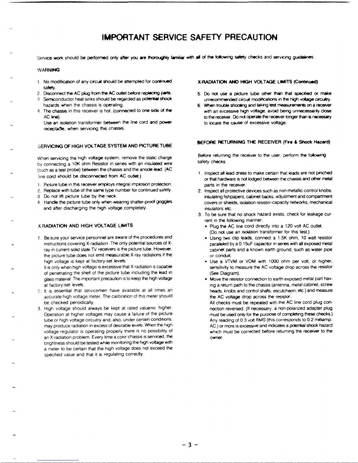
IMPORTANT SERVICE SAFETY PRECAUTION (Continued)
TO
EXPOSED
METAL
PARTS
CONNECT
TO
KNOWN
EARTH
GROUND
- 4 -
SAFETY NOTICE
Many electrical
and
mechanical parts
in
television receivers have
special safety-related characteristics. These charactenstics are often
not evident from visual Inspection nor can the protectIOn afforded
by
them be necessarily increased by using replacement components
rated for higher voltage, wattage, etc. Replacement parts which have
these special safety charactenstlcs are Identified
In
this manual; electncal components having such features are identified by "@"and shaded areas
In
the Replacement Parts Lists and Schematic Diagrams.
For continued protection, replacement parts must be identical
to
those
used
In
the original CirculI. The use of a substitute replacement part
which does not have the same safety characteristics as the factory
recommended replacement parts shown
In
this service manual, may
creilte shock, fire, X radiation
or
other hazards.
..
til>
...
...
-
..
...
MAJOR CIRCUIT FEATURES
1.
Newly developed components.
Hybrid-IC type
STR
470A serves the stable B + output against
input and load variations.
In
application of this reliable component, the power
Circuit
has merits
as
listed:
a No adjustment for B
+ (DC115) output
IS
necessary.
b.
Simplification of the circuit.
c.
No voltage setting against the variation of main power voltage
is
necessary.
2.
MSI
(Medium Scale Intergrated Circuit)
This Monitor Consists of 3 MSls.
Each MSI
IS
prOVided with the function of the conventional circuits,
which enables
rt
to improve reliability and stability of picture quality
by reducing the number of parts and adjusting points.
3.
Low Loss Vertical Output CircuIt.
The power loss
In
the vertical output circuit
IS
reduced by changing
over from high voltage to low voltage
In
the front and back halves
of
the scanning period.
4.
High voltage Circuit
FBT (flyback transformer)
is
multl-smgle type, that
is,
high voltage
rectifier diodes are connected, between high voltage windmg, and
these are sealed.
This FBT decreases the variation of picture size and reduces the
dragging
of
the picture. The raised high voltage improves focuss-
Ing to make picture quality better.
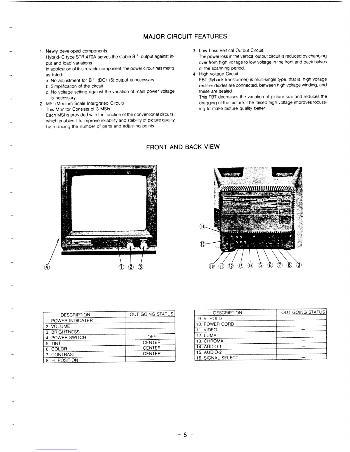
FRONT AND
BACK
VIEW
DESCRIPTION OUT GOING STATUS
DESCRIPTION
OUT GOING STATUS
1.
POWER INDICATER
9.
V HOLD
-
2.
VOLUME
10.
POWER
CORD
-
3
BRIGHTNESS
11.
VIDEO
4.
POWER SWITCH
OFF
12. LUMA
-
5.
TINT CENTER
13. CHROMA
-
6.
COLOR
CENTER
14.
AUDIO-1
-
7.
CONTRAST
CENTER
15. AUDIO-2
-
8.
H.
POSITION
-
16. SIGNAL SELECT
-
-5-
, ............ ------------------.... --------------------.......
----
....
--_
...
_ ........
----
......
----~--
............
--
CIRCUIT DESCRIPTIONS
1, POWER
SUPPLY
This Monitor
power
supply
IS
switching
mode
power
supply (SMPS)
that
is
consist of sWitching
IC
(IC901), SMPS TRANSFORMER
(TOO
1 )
pulse TRANSFORMER (T902) and assoCiated
component
The
BasIC
theory of the SMPS
IS
the circuit of Blocking Oscillation
and
by
tur'
ning ON, OFF of STRA470A. the secondary of the SMPS TRANS
is
applied
the pulse, Instant + 115V DC that pulse
is
rectlflred
IS
abtalns.
All other operating voltage and pulse are
drlved
from the
secondary
winding
of
the
high
voltage transformer (also
called FBT. T703)
2.
ST
Mn
UP
CIRCUIT
An
Initial start·up Circuit provides drive to the horlzontlal output stage
when
the set
IS
Initially turned on
ThiS
CIrcUIt
consists of
0703
and associated components
It
proveds
the Initial voltage necessary to activate IC701
and
pro·
vldes a drive pulse to the hOrizontal drive transistor
0701
Once
the FBT·drived voltages operational
0708
IS
forward· biased
and
0701
is
reverse-biared. prOViding + 45V DC
to
IC701 and 0701
SWitching voltage
supply
CirCUit
like
tr,IS
results
In
saving
power
consumption
3.
HORIZONTAL
DEFLECTION
SYNCHRONIZATION
AND
VERTICAL
Integrated Circuit IC701 perlorms the hOflzontal synchronIZation (also
called horizontal oscl'lator)
A hOrizontal rate output pulse
IS
coupled
from IC701 pin 15
to
hOrlzontai driver
0701.
The driver stage dflves the hOflzorltai out
put
0702.
HOrizontal synchronization slg'1al
IS
derived fronc composite v'deo
Signal which
coupled
to
IC701
pin
10.
Vertical synchronization signal
'5 derived from composite signal at
IC701 pin 8
and
coupled
to
pin 7 through R601
4.
HORIZONTAL
AFC
AND
OSCILLATION
LlMITIER
AFC Circuit
IS
conSists ot phase detection
CirCUit
of IC701 and
0704.
associated
component
Oscillation
limiT
CirCUit
.s
necessarv to
P'8-
vent from excessive high voltage.
ThiS
CirCUit
IS
located
In
IC70
1
and
controls the
OSCillator
to maintain the control signal
In
correct
frequency
and
phase w'th the hOfllonta' sync signal
5.
X-RAY
PROTECTION
CIRCUIT
Hle
X-ray protection
CIiCUltlS
consists
of
0703.
R731
(Hold. Down)
R729. R730
and
assoCiated
ccmponent
that connected to
pl'l
16
of IC701
A pulse
j'om
~BT
Pl~i
6 is rectified by
0705
Under nor-
mal operating condlt!OrlS. tne resui'a'lt voltage maintains
at
specified
value
If
a rna!f,mctlon causes excessive nigh
vOltage.
me
amplitude of pulse
from FBT Increases. cauSing a
corresponding
Increase
In
0703
which
results
In
vos!tage Increase at pin 16 of IC701. Voltage
In-
crease
at
IC701 pin 16 makes
Xray
protection cirCUit
conduct
and
hOrizontal oscliatlon operation
no
longer function.
The
C!fCUlt
wlil latch as
above
and
the IIlstrument
IS
necessary to
turn off for
at
least
30
seconds
to function again
6.
VERTICAL
OSCILLATION/DRIVE
CIRCUIT
Vertical oscillation and drive
CirCUit
are located
In
IC701 R603. R605.
R606
C604
and
R604
which
connected
at IC701 pin 6 are time
constant
CirCUit
that determine the verllcal
OSCillation
frequency
Vertical size control function
IS
performed
by
R604 causing the
negative
feed
back
to change.
7.
VERTICAL
OUTPUT
0601
and
0602
are SRPP (SHUNT
REGULATED
PUSH
PULL)
vertical output cllcuit.
45V-supply through
0604.
0605.
C6Q8 is the main voltage
supply line
R620. C613.
0603
IS
pump
up
circurt
whICh
supplies sufflCl9nt cur-
rent driVing the first half of vertical scan
8.
HORIZONTAL
DRIVE
CIRCUIT
To obtain horizontal drive Du'ses irOrr!
IC70t
Din
15
the honzon-
tal OsCli!3tor must be
wor"ng.
Horizontal
dnve
pulses
Irom
IC701 pin
15
are applied to hOrizon-
tal driver
0701.
8 + for
0701
\S
is
supplied from 45V line
through
0708.
OU'lng ''l'lial receiver turn·on before the
FElT
-DRIVED
SUPPL Y VOLTAGE ARE DEVELOPED.
0701
IS
s,,)plied
Initial
B + from the regul,'ted 115 volt I:ne through R736
9.
HORIZONTAL
OUTPUT
Horizontal
dnve
pulses from
0701
are coupled
through
T703
CO
the bare of hOrlzon[al output
0702.
0702
is
biased on when the
beam
IS
at
about
mid-screen.
The
charge
stored on C724.
C729
cause~current
to flow
through
the hOrizontal yoke Winding and
0702
to g'JI_!IId. When the
beam
reaches the fight
Side
of the screen.
0702
IS
turned off
and
the
current
In
the yoke
IS
dllected
Into C719. C720
At
the same time
current flows Into C719.
C720
from the regulated B + via the FBT
pnmary
Winding
Due
to
resonance. the current then reverses
ard
flows back through
the hOllzontai yoke Winding Into C724,
C729
This action aefects
the electron
beafT1
back to the 4- 115V regulated B + .
10.
PINCUSHION
CORRECTION
Pincushion
correction
CIICUlt
IS
T702
and
ItS
associated
components.
HOrizontal yoke current
IS
Increased or
decreased
In
response to
vertlca' parabola pulse The
CirCUit
of
0751
0752,
T751
and
assoclatea component.
IS
for
Improving
high voltage translcent
response
11.
POWER
SUPPLY
DETAIL
DESCRIPTIONS
- 6 -
RCC
(RINGING
CHOKE
CONVERTER)
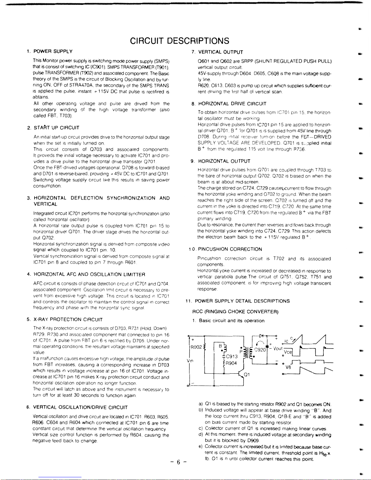
1.
Basic
circuit
and
its
operation
+
r:;-r~~
R902
fB.)
;
I~
~92;1'
V~O<:qJ~
C913
I.
0
R904
-0
~
01
~
-
~-------~--------~
a)
01
IS
biased by the starting resistor R902 and
01
becomes ON.
b)
Induced
voltage will appear
at
base drive
winding
"B"
And
the loop current thru C913. R904.
01BE
and
"B"
IS
added
on bias current
made
by
starting resistor.
c) Collector current of
01
is increased rnaking linear
curves
d)
At
thiS
moment. there
IS
Induced
voltage at secondary Winding
but
It
is
blocked
by
0909.
e) Collector current
is
Increased
but
rt
is
limited because base cur-
rent
IS
cons:ant. The limited current, threshold pOint
IS
Hie
x
lb.
01
is n until collector current reaches this point.
-
..
-
-
-
-
...
f)
During
Q1
is
ON, input vonage Yin
is
added on the primary
winding P But,
it
is
added on
Q1
C-E
suddenly.
g) At same time, inverted voltage appears at
"B"
which will bias
Q1
B·E reversely and
Q1
is OFF.
h) The energy charged in
P
is
discharged
by
the secondary
winding S thru D909.
i)
Q1
B-E
biased reversely.
j)
The energy
is
discharged thru D909 and when
Id
is
zero,
starting current
by
R902 makes
Q1
on again.
Repeating from
(a).
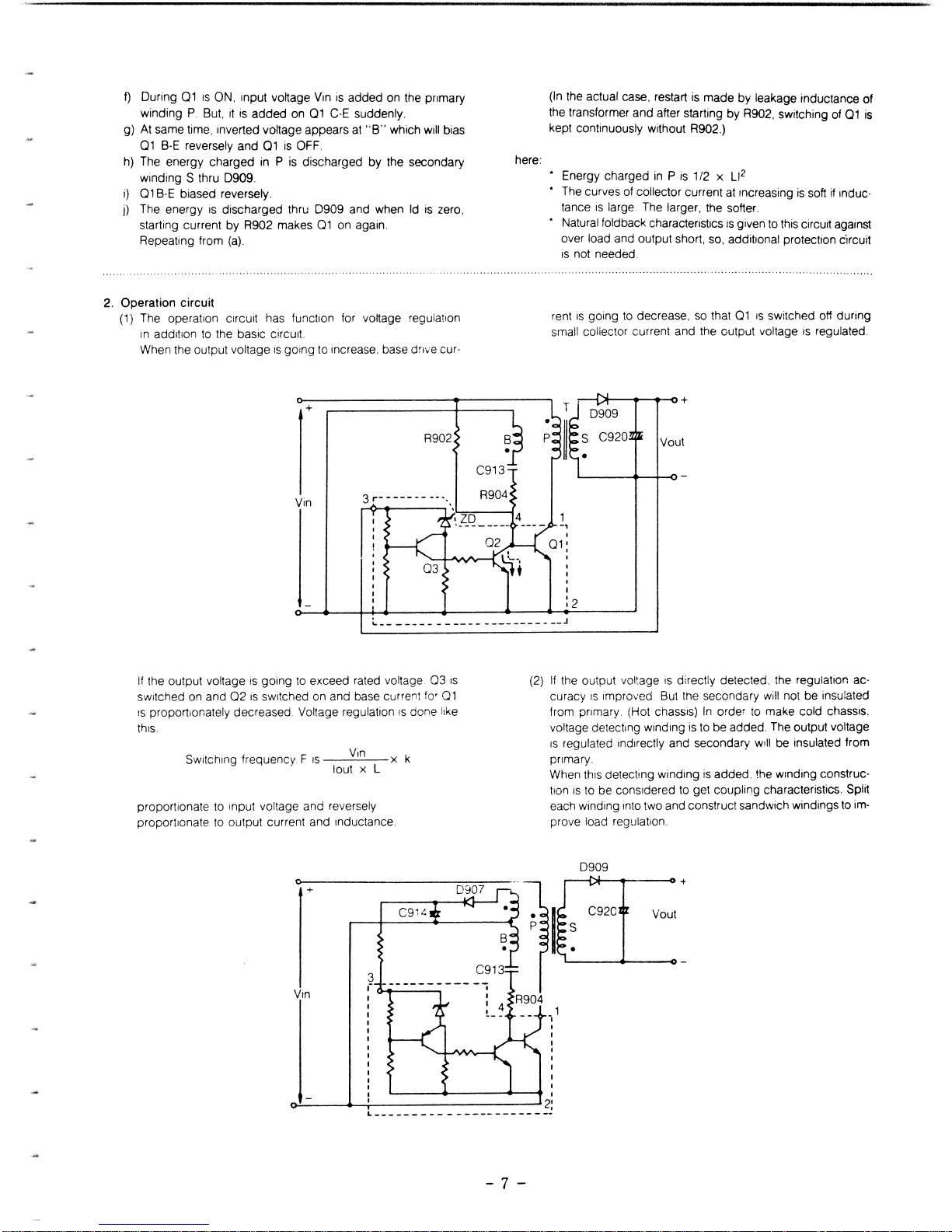
2. Operation circuit
(1) The operation Circuit has function for voltage regulation
in addition to the basic
cirCUIt.
When the output voltage
is
going to increase. base drive cur·
+
Yin
here:
(In the actual case, restart
is
made by leakage inductance of
the transformer and after starting by R902, switching of
Q1
is
kept continuously without R902.)
* Energy charged
in P is
1/2
X
Ll2
* The curves of collector current
at
Increasing
is
soft
if
induc·
tance
is
large. The larger, the softer.
Natural fold back characteristics
is
given to
this
circuit against
over load and output short, so, addibonal protection circuit
is
not needed.
rent
is
going
to
decrease,
so
that
Ql
IS
switched off during
small collector current and the output voltage
is
regulated.
.---Dl-
__
~
+
0909
S C920
Vout
•
________________________
J
If
the output voltage
is
going to exceed rated voltage. Q3
IS
switched on and Q2
is
switched on and base current for
Ql
IS
proportionately decreased Voltage regulation
IS
done like
this.
Yin
Switching frequency F
IS
X k
lout x L
proportionate to input voltage and reversely
proportionate to output current and inductance.
+
3
fo.-.
__
--.
(2)
If
the output voltage
is
directly detected. the regulation ac·
curacy
is
Improved. But the secondary will not be insulated
from primary. (Hot chassis)
In
order to make cold chassis.
voltage detecting winding
is
to be added. The output voltage
IS
regulated indirectly and secondary
w,1I
be insulated from
primary.
When this detecting winding
is
added. the Winding construc·
tlon
is
to be conSidered
to
get coupling characteristics. Split
each winding Into two and construct sandwich windings to im·
prove load regulation.
0909
.--1::.1--_---0
+
C920 Vout
s
•
I
~---~T-----------~2:
L
___________
- ---- - - - -
-_
...
- 7 -
 Loading...