

Commodore Amiga AS90 Hard Drive Plus User Manual
C:
Commodore
® E - -
AMIGA
®
~£
_
HARD DRIVE PLUS
USER'S
GUIDE
DRIVE
INFORMATIO
N
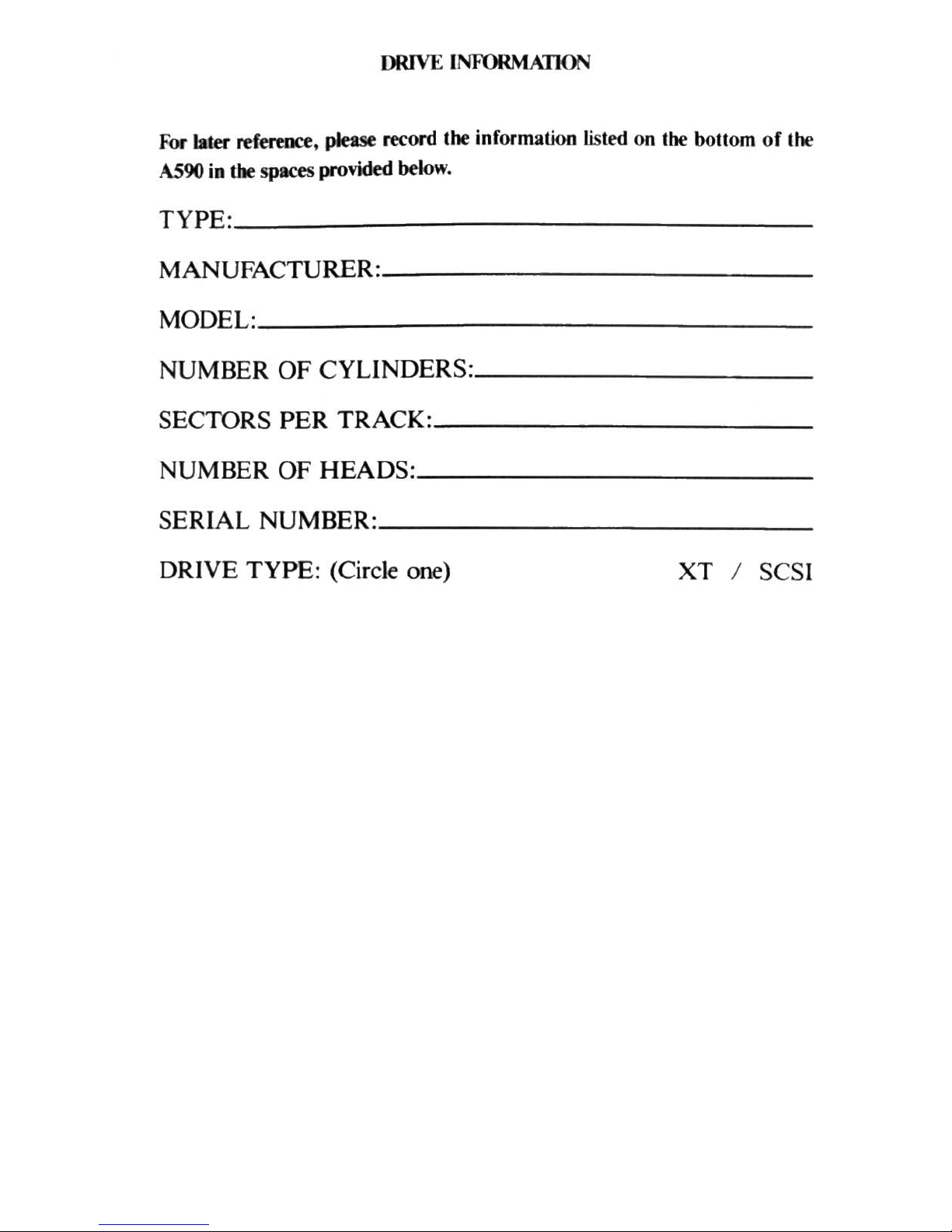
For later reference, please record the information listed on the bOllom
of
the
AS90
in
the spaces provided below.
TYPE :
______
__________________________
_
MANUFACTURER:
____________
__________
_
MODEL:
____________________________
_
NUMBER OF CYLINDERS::
____
______________
_
SECTORSPERTRACK::
____________________
__
NUMBER OF HEADS:
__________
__________
_
SERIAL NUMBER::
__________________
____
_
DRIVE TYPE: (Circle one)
XT / SCSI
C:
Commodore
®
~
- -
AMIGA
®
~~-
_
HARD DRIVE PLUS
USER'S
GUIDE
CO PYR I
GHT
Thi
s manual .
1:
)
19
89
Commodore-
Amiga
. Inc ..
All
Ri
~hls
Reserved.
Thi
s document may nO
I,
m who
le
or
in
pari
be
copied, photocopied. reprodu ced.
tran
slated, or reduced 10 any
elc
~"
Ironic
f1l('dium or
machine
readable
form. without
prior cons
ent,
in ""riling.
fmrn
Commodore
-Amiga. Inc.
With
Ihis dOCUlTI(nt,
Commodore-Amiga
makes no warranti{'
",
or
guaraflll!c
~.
ejlhN
nj)re
v,cd
or imp l
ie
d.
wilh
respect to
t~
products described. the ir
fUrK:liona1i
'~'
.
compatibility.
or
3\ail
·
ability.
FUrl~r.
Commodo
... !-Am
iga assumes no re<;pomitJility or liabilit}' for
"
Ialemcnl
~
or
repre!!cmali
ons
made by itSelf
or
by
third
party
vendor-. or in
the
puhllc
ation'
repr(ldu~'ed
herein. IN
NO
EVENT WILL COMMODORE-AMIGA
BE
LlAHLE
FOR DIRi:.
CT, IND
I·
RECT. INCI
DENTAL.
OR
CONSE
QUENTIAL
DAMAGES RE
SULTING FROM
ANY
CLAIM
ARISING
OUT
OF
THE
REPRESENTATIONS
MADE
HEREIN. [VE:-.I
IF
IT
HA
S BEEN
ADVISED OF
THE POSSIBILITIE
S OF SUCH DAMAGES.
SO
~1E
STATES
DO
NOT
ALLOW
THE
EXCLUSION OR
LIMI
TATION OF
SUC
H WARRANTIES OR
DAMAGES.
SO
THE ABOVE EXCLUSIONS
OR
LIM
IT
AT
IONS
MAY
NDT
A PPL \'.
Inf
orma
tion in this document is subject to
change
",;,h(\u! nOlice and doc s nOI represent a
commitmen t
on
the
part
of
Commodore-
Amiga.
The
software described
in Ihi' doc
ument
i
~
furni~d
under aiKen$(' agreemem or
nond
isclo~urc
agreemt'nl. 11
b.
a
g:timt t
he
la
....
10
l'O
p~
Ihi\
sof","'are
on
magnetic
tape
.
di
sk.
or any athel medium for any pUr
ptN::'
Olher than
lhe-
purcha!>er'~
personal
use
.
Anllga
i~
a
registere
d trademark
of Comm
odore-
Ami
ga. In
c.
Cum mod
ore
:tlld the Commo-
dore 10iO are registered
trademarks
of
Com
modore Eleclronic\
Limited . 1\-IS·00S
i~
..
1
re.cl'"
lered
trademark of
the Microsoft
Corpo
ration . PC : XT j, a Tegi",ered
Iradclllar~
of IrHcrna-
lional
Bu
sineu
Ma
chines,
Inc . UNIX
i~
a regi s
terc=d
Irade=mark
of
AT&T.
Ep
~(l
n
10,
3
rc=
gi~
t~r~d
Iradt-mark
of
Epson
Amc:rka,
Inc.
SeagalC=
is a
f~glslcrcd
trademark of
Scagate Tec
hnolog
ies.
Inc.
WARNING: This
equ
ipnl(nI
has
bttn cenific=d 10
comply
v.ilh
the
limits for a Cla ss B
..::o
mpul-
ing
devicc=.
pursuant
to subpart
J of
Pan
15
of
the Federal
Communicalion
~
Commissions
rules.
and
Standard
C I
08.8·
M 1983
of
the Can
adian
Slandard~ AS~OCl
ation'
)
regulation
...
T~
ru
les a nd regul
ations
are designed to
provide
rca so
nahle
protcc
tion
again
st
radio
and
te1evi~ion
inter ference in a res idential
insta
llation . H TlC'l
in'ta
lled
properl
y.
in "triet a
ceor·
dano.:e
.....
ith
the manufact u
rer's
ins
truction
s.
it
may
cau,e
interfer ence. If you
~tI~
P~(t
illlcrf\.·r-
erlCe. you
ca
n test this
equipment
by
turning il
on
and
off. If
thh
('4uipment d
oe, cau
se
interference.
COf
rect
it
by
doing
any
of
the
following :
•
R
eor~
ntl~
receiving
antenna
or
plug .
•
Cha
nge
the
relati\,(, positions
of
the
peripheral
and Ihe receiver.
~
Plug the
equipment
into
a diffe rent outlet
so
thai
the
peripheral
and
recei ' er
arc
on
different
circui ls.
C
AUTION: Only
equipment
with
shield -gr
ounded
cables (cO
mpUleT
input
-output
de\ice
~
.
ter-
m
Lnal
s.
printe
rs. et
c.), ce
rtified 10 comply
with
Cla
ss B limi ts. c
an
be
all ached
to this devi et'.
Oreration
with non-ce
rtif
ied
equipment
may
result in
communica
tions illlerferen ee.
)'
('I
UT
house AC wall
receptacle
must
be
a three -
pronged
type (AC'
ground)
. If
nm. conta
ct
an
ck(trician
to in stall
the
proper
receptacle
.
If
a
multi
-co
nTlC1:tor
box
is used
to
":('I
nnect the
(Ompu
tl'r
and
peripherals
to AC'.
the
grou
nd
mu
~t
be
common
to
all unit
).
I f
ne(c~sary.
contact
your
Commodore
dealer
or
an
expc=ricl
'k.'
cd
radio·TV tet.:hmci.m
for
addi
-
tional
\
uggc"'ion~
.
Y
ou
may
find
the following FCC' boo
klet
help
ful : " How
10 Identify
and
R
c\olve
Rad io-
TV
InterfercO(e Problem>;
." The
boo
klet i
..,
availab
le from the U .S . Gt,,,,:rn-
men I
p,
i nt ing
Office.
\\'a
shi
ngt0n, D.C.
20402.
stock no.
()()..l-()()()·{IOH5--'.

Contents
INTRODUC I
NG
THE
A590 ...................
.
.............
.
..
.
STALLING
THE
A590 ..............................
.
........
3
Installation
Pr
ocedure ........
..............................
3
Connecting External SCSI Devices
.....................
.
......
8
In
stalling R
ando
m Access Memory (RAM) Chips
................
8
USING
THE
HARD
DISK
...........................
............
15
Copying Pr ograms to Your Hard Disk
........
.•.
..
. .......
....
15
Saving/
RelTievin
g Files .
........
.
......
..
. .
.•.
..... .
....
.... 19
Backing Up Your Hard Disk
...
........
..
............
........
19
Re
coverable Errors
........
.
...............
. . .
.........
20
Nonrecoverable Errors
.............
........
.......
..... 20
CHANGING
THE
STARTUP·SEQUENCE ..........
.
.............
23
THE
A590
SETUP
DISK
...
.....
.............
..
.................
25
Ki
cks
taTl 1.3
Users
......
..
.....•..
.... .
......
.. ..
...
•.
..... 25
Ki
cks
taTl
1.2 Users
.............•.
. . .
.........
.
.............
26
Quick
In
stallation
...
..
...
..
........
.
....
. . .
........
........
26
Using the A590 Setup Disk
..................
.
.........
...
....
27
Using the Installation Soflware
....................
.
....
. 28
Usi
ng the
HDToolbox Prog
ram
..........................
34
Hard Drive Preparation , Pa
Tliti
oning and Formalling
...
35
Change Drive Type
.....
.
.......
.
.................
39
Define/ Edit Drive Type
.........
.
................
.41
Bad Bloc
ks
.....
.
............
..•.......
:
......
. . .43
Parll llonmg
....
..
..............
.
................
44
File
Sys
tem Characterist ics . ....
.................
. . .49
File System Maintenance
.......
....
.....
..
.........
51
APPENDIX
A TROUBLES H
OOTING
...
....
....................
53
APPENDIX
B DIP S
WIT
CH SETTINGS
...........
...
..........
54
APPEND
IX C
TECHN
ICAL
SPECIF
ICATIONS .
......
..... .
.....
55
APPENDIX
D SOME USEFUL
TERMS
....................
.
....
61

Introducing
the
A590
The AS90
Hard
Drive Plus
is
an external hard disk drive plus a controller
card and expansion memory unit for the Amiga
SOO.
The AS90 connects to
the side
of
the Amiga
SOO
and comes with a disk containing all the softwa re
required for operation.
The AS90 includes the following features:
• 20
MB
of
disk
slO
rage.
• Sockets for SI2KB, 1MB, or 2MB
of
fast rand om access memory
(RAM)
chips.
• Direct Memory Access (DMA) for fastest possible operation.
• ConneclOr for the use
of
Small Computer Standard Interface
(SCSI) expansion devices.
• Autoboot ROMS to allow you to boot your system from the hard
drive, if
you
are using
Kickstan~
1.3.
Note:
To
obtain the full potential
of
the AS90,
you
will want
10
have the
Kickstan 1
.3
ROM
upgrade installed
in
your Amiga
SOO.
With the Kickstan
1.3
ROM
s you will be able to automatically
boO!
your system from the AS90,
providing faster access to all your files.
You
can determine whether your Amiga has Kickstan 1.2 or 1.3 by
staning
your system without a disk
in
the floppy drive. The screen
will
show a hand
holding a Workbench disk, with the version number below
it.
If the version
number
is
1.2, your. Amiga is using Kickstart 1.2. Please see your Amiga
dealer concerning the
ROM
upgrade.
If
the version number
is
1.3, your
Amiga already has Kickstan 1.3.
This user's guide explains how to:
• connect and set up the AS90.
• connect external SCSI devices.
• install RAM chips on the AS90 board.
• use the HDToolbox software to set up and configure your
hard disk.
•
use
the
reinstallation software
(0
rebuild
you
r hard
disk
in
the
event
of
a catastrophic loss
of
data .
Note that with the addition
of
the A590, your system will still operate nor-
mally using the floppy disk drive.

Installing
the
A590
WARNING: Commodore will not be responsible for any injury
or
damage
resulting from improper installation. Such improper installation will also
void the warranties on the A590 and the Amiga 500. Read this manual before
attempting to
in
stall the A590. Turn the computer
off
and unplug the power
cord before proceeding. Installing the A590 with the power on could cause
personal injury to
yo
urself and damage to the equipment. Make sure that
nothing is attached to the computer. Disconnect all peripherals and power
cords, and put them aside. The A590 requires adequate ventilation. Do not
block the openings in the A590
or
place
it
in
an enclosure
or
on
a carpet.
Most hard disk failures
occur
due to improper handling: never subject the
A590 to electrical
or phys
ical shock.
Unpack the A590 a
nd
make sure that
you
have a
ll
the requir
ed
part
s:
• A590 hard disk drive.
•
gro
und clip.
• power supply.
• A590 setup disk
• warranty card.
Record the information listed on the bottom
of
the A590
on
the inside cover
of
this manual.
Installation
Procedure
The following steps, required to install the A590, are explained
in
detail,
heginning on the next page.
I. Turn
off
and disconnect the A500.
2.
Set the
DIP switches
at the back
of
the A590.
3.
Open the side panel
of
the Amiga 500.
4.
Co
nnect the ground clip 10 the Amiga 500.
5.
Co
nnect the A590 to the Amiga 500.
6.
Co
nnect the power supply to the A590 and AC outlet.
J
1.
Turn
off
and
diseonnect the A500.
Thrn
off
the
ASOO,
and
unp
lug the power cable. Disconnect a
ll
peripherals
and c
ab
les from the
ASOO.
2. Se tting the
DIP
switches.
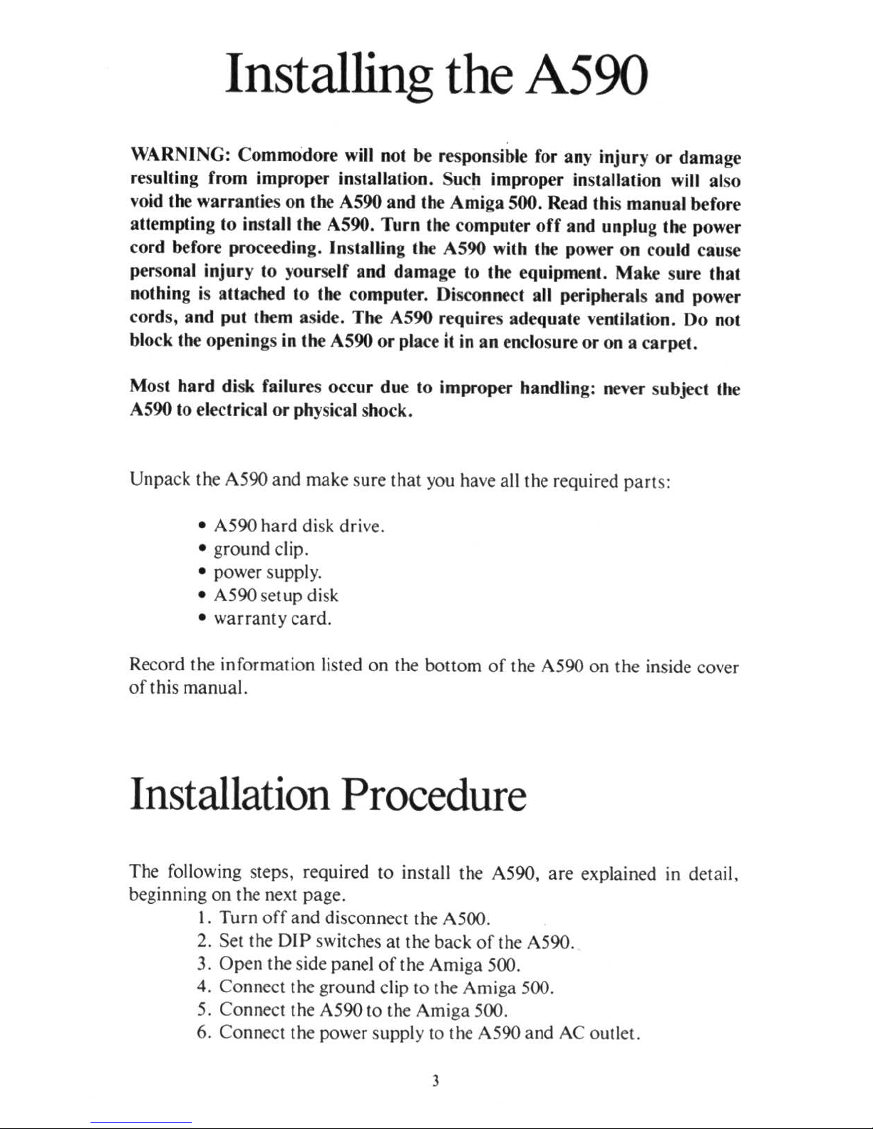
There
are four
DIP
switches l
oca
ted at the back
of
the AS90.
The swit
ches
are
shipped in the
off
pos
ition.
If
you
are
using Kicks
tart
1.3
you will want to
set
DIP
swi tch I
to
on.
If you
are
using Kicks
tart 1.2 you can connect the
AS90 with
the DIP
switches in the cu
rren
t position s.
Note: If yo
ur Workb
enchm prompt
requests Workb ench 1.3, you
are
using
Kicks
tart 1.3.
If
it
request s Wo
rkb
ench 1.2, you are using Kicks
tart
1.2.
DIP
switch I enables and disables the
Aut
oboo
t ROM s.
DIP
switch 2 con·
trois whether the syst
em
will look for more
than
one drive at each logical
SCSI add
ress.
DIP
switch 3 sets a long or short delay between when you
turn
the power on
and
when yo
ur
system checks the drives. DIP swi tch 4 is
reserved for later use.
DIP swit
ches 2
and 3 are onl
y used with external
SCS
I
drives. Fo r more informati on
on the 01 P swit ches refer to Appendix B .
'.
::
::
"
..
'.
"
...
'j
.
.
~
.
:
" .
• •••••••••••••
••••••••••••
po
.....
er
C
onoeclOf
•
ole:
Each
switch is
off
when in the
down
position,
and on when in the
up
posirion.
4
The A590 is supplied wilh a
ll
swilches ofr. The AUlobool
ROMs are
disabled;
Ihe
sYSle
m will look for only one device al each physical address; and Ihe
sys
tem
will
allow a sho
rt
amount
of
time
between
when
it
powers
up
and
when
il
checks Ihe dri
ves
.
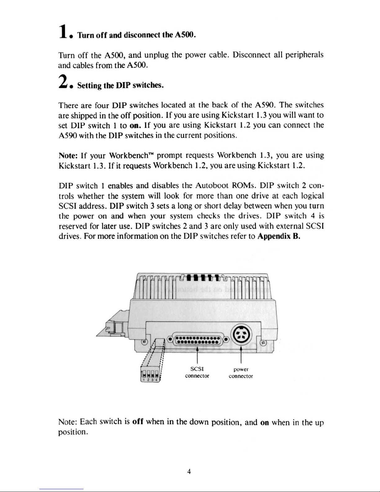
3.
Op
ening t
he
Amig.
500.
There is a panel on Ihe l
efl si
de
of
the compulcr Ihal mu
Sl
be removed
10
ex
pose Ihe connecl
or lab
10
be used
by
the A590. In
sen
a small screwdriver
in Ihe SIOI, and
puillhe
panel down and away from Ihe computer.
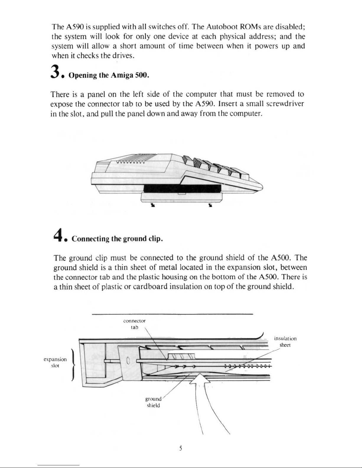
4.
Co
nnecting the grou
nd clip.
The ground clip muSl be connecled
10
the gro und shie
ld
of
the A500 . The
ground s
hield
is
a Ihin sheel
of
metallocaled
in
Ihe expansion S
IOI,
bel ween
Ihe connector
tab
and the plasli c housing on Ihe bOllom
of
the A500. The
re
is
a thin sheel
of
plaSlic or c
ardboard insulalion on
lOp
of Ihe ground shield.
C
Qflntt
lOf
b
..
\
.
\ \
,
~
Y
''''''nd
/
\h~kI
5
./
/'
/'
~
\
'"'
uta! IOn
""'"
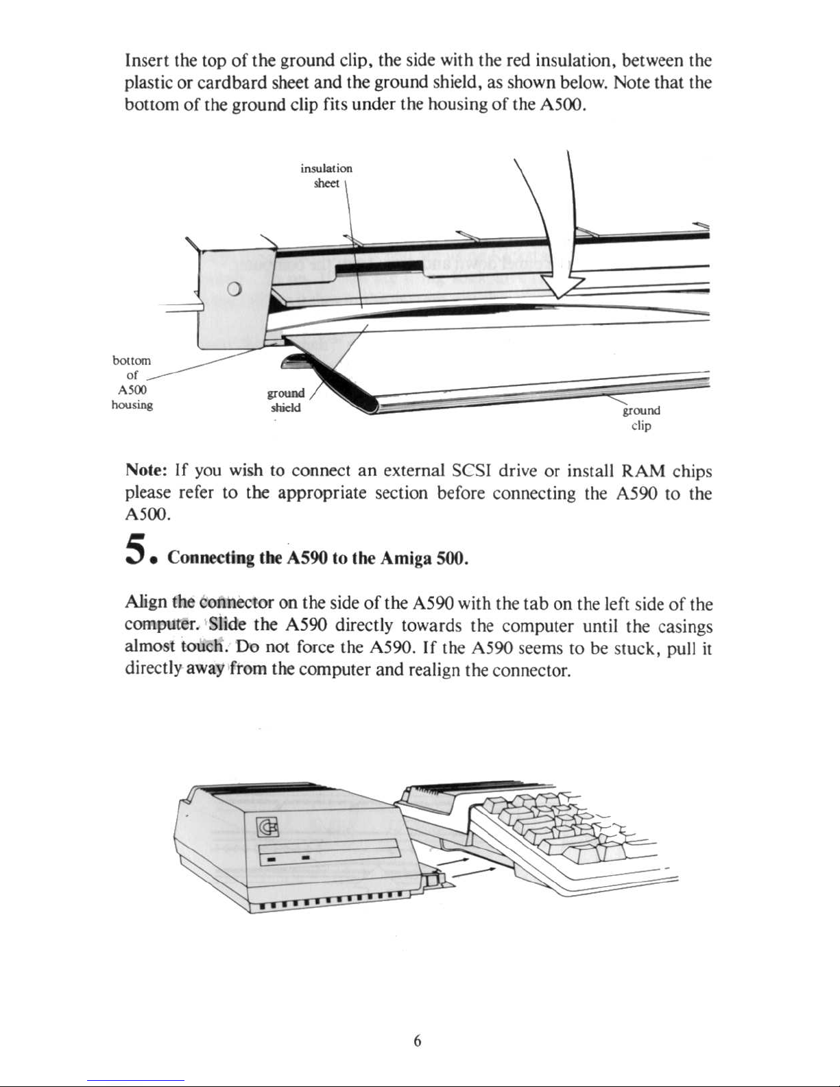
Insert the top
of
the ground clip, the side with the red insulation, between the
plastic or
cardbard
sheet and the ground shield, as shown
below.
Note that the
bOllom
of
the ground clip fits under the housing
of
the A500.
bouom
or
Aloo
housino
insulation
......
,,,,,,
",,
sIridd
",(lUnd
clip
-
Note:
If
you
wish to connect
an
external SCSI drive or install RAM chips
please refer to tbe appropriate section before co nnecting the A590 to the
A500.
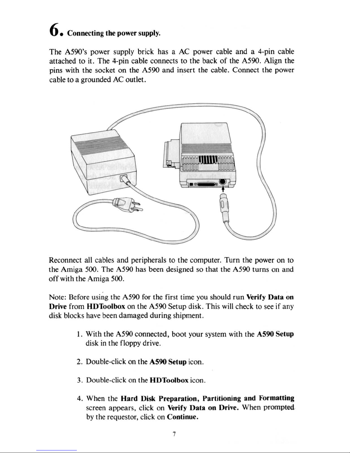
5. Conneeling the A590 to the Amiga 500.
Align the connector on the side
of
the A590 with the tab on the left side
of
the
computer. Slide the A590 directly towards the co mputer umil the casings
almost touch. Do not force the A590. If the A590 seems to
be slUck,
pull
it
directly away from the computer and realign the connector.
6
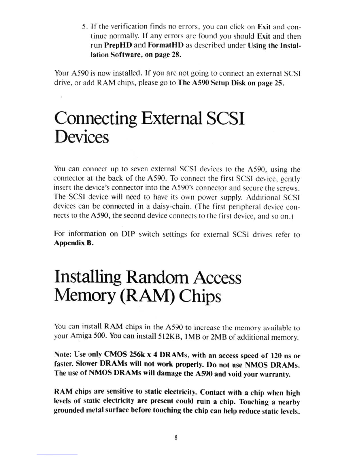
6. Connecting lhe power supply.
The A590's power supply brick has a AC power cable
and
a 4'pin cable
allached to it. The 4-pin cable connects to the back
of
the A590. Align the
pi
ns with Ihe socket on the A590 and insert the cable. Connect the power
cable to a grounded AC ou
tl
et.
Reconneci all cables and peripherals to the computer. Thrn the power on
to
the Amiga 500. The A590 has been designed so that the A590 turns on and
off with the Amiga 500 .
.
Note: Befo
re usin
g the A590
for
the first time
you
should run Verify 001 a on
Dri
ve
from HDToolbox on Ihe A590 Setup disk. This
will check
to
see if an y
disk blocks ha
ve
been damaged during shipment .
I. With the A590 connecled, boot your system with the A590
Se
lup
disk
in
the floppy drive.
2. Double
-cli
ck on the A590 Setup icon.
3. Double-
cli
ck on the
HO
Toolb
ox icon.
4.
When the Hard Disk Preparation, Part ilioning a
nd Formalling
sc
reen appears, cl
ick
on Verify Oala on Drive.
Wh
en prompled
by
the requestor, click on Continu
e.
7
5. If lhe verifica tion finds 110
crror~,
you
GlIl
di
ck on Exit
and
con-
tinue normall
y.
If
any error,
arc found yO
ll
~
tlOuld
Exit
and
then
rLin
PrepHIJ
and
Formal/H)
'" described Lind
er
U
sin
~
the
Instal·
lation Software. on
pag
e 28.
YOllr
A590
is now in
stalled . If you are
110t
going
to connect
an
external SCS
I
drive.
or
add
RAM chip
s. plea se
go
to
The
A590 Setup
Disk on page 25.
Connecting External SCSI
Devices
You can connect
up
to s
even external CSI devices 10 the A590, using
the
connector
at
the
back
of the
A590
. To
connect
the first
SCS
I device. gently
insert {he devi
ce's connector
into the A 590'
;;
con
neclOr
and
"iccurc
th
e screws.
The SCS
I de vice will need to have its own power s
Lippl
y.
Add itional
SCS
I
devices c
an
be
co
nnected in a
dai
sy-chain. (The first peripheral dc\'i
re
co
n-
nec
tS 10
the
A590,
I he second device
connect ~ to
Ille.?
fir\1 device.
and
"0
on.)
For
inf
ormation
on
DIP swit ch settings for external
SCS
I driv
es
refer 10
Appendi,
B.
Installing Random
Access
Memory (RAM) Chips
You can ins
tall
RAM chip
s in
the
A590 to increase the me
ill
ory available
to
yo
ur
Ami
ga
500. Y
ou can install 5 12K B, I
MB
or 2M B
of
add
itional m
emory.
Note: Use only C
MO
S 2S6k x 4
DRAM
s.
with
an
access speed
of
120 ns
or
faster. Slower
DRAMs
will
not
work
properly. Do
not
use
:-I
MOS DR
AMs.
The
use
of
NMOS
DRAM
s will
damage
the
AS90
and
void your
warranty
.
RAM
chip s
are
sensitive
to static
elcctricily. Cont
act
with
a c
hip
when high
levels
of
static elf'Ctricity
are
present could
ruin
a c
hip.
Touching a ncarb)'
gro
und
ed
metal surfa
ce before
touching the chip can help
rrdu
ce stat
ic
I{'nls
.
8
In
stallation
of
RAM chips should
be
performed
by
an authorized Commo-
dore Service Ce.nter, or
by your Commodore dealer. Commodore will not be
responsible or liable for any damages caused by improper insta
ll
atio n
of
RAM chips.
WARNI
NG
: If your A590
is
co nn ected
10
the computer,
you
mu
st first turn
off the power, disconnect a
ll
cables and peripherals, and detach the A590
from the computer
by
carefully pulling the A590 directly away from the
A500.
The following steps, required to install RAM chips, are explained
in
detail
below.
I. Remove the A590's cover.
2.
Remove the dr
ive and
the drive shield.
3. Insert the RAM chips.
4. Set the RAM size jumper.
5.
Replace the dri
ve
and the cover.
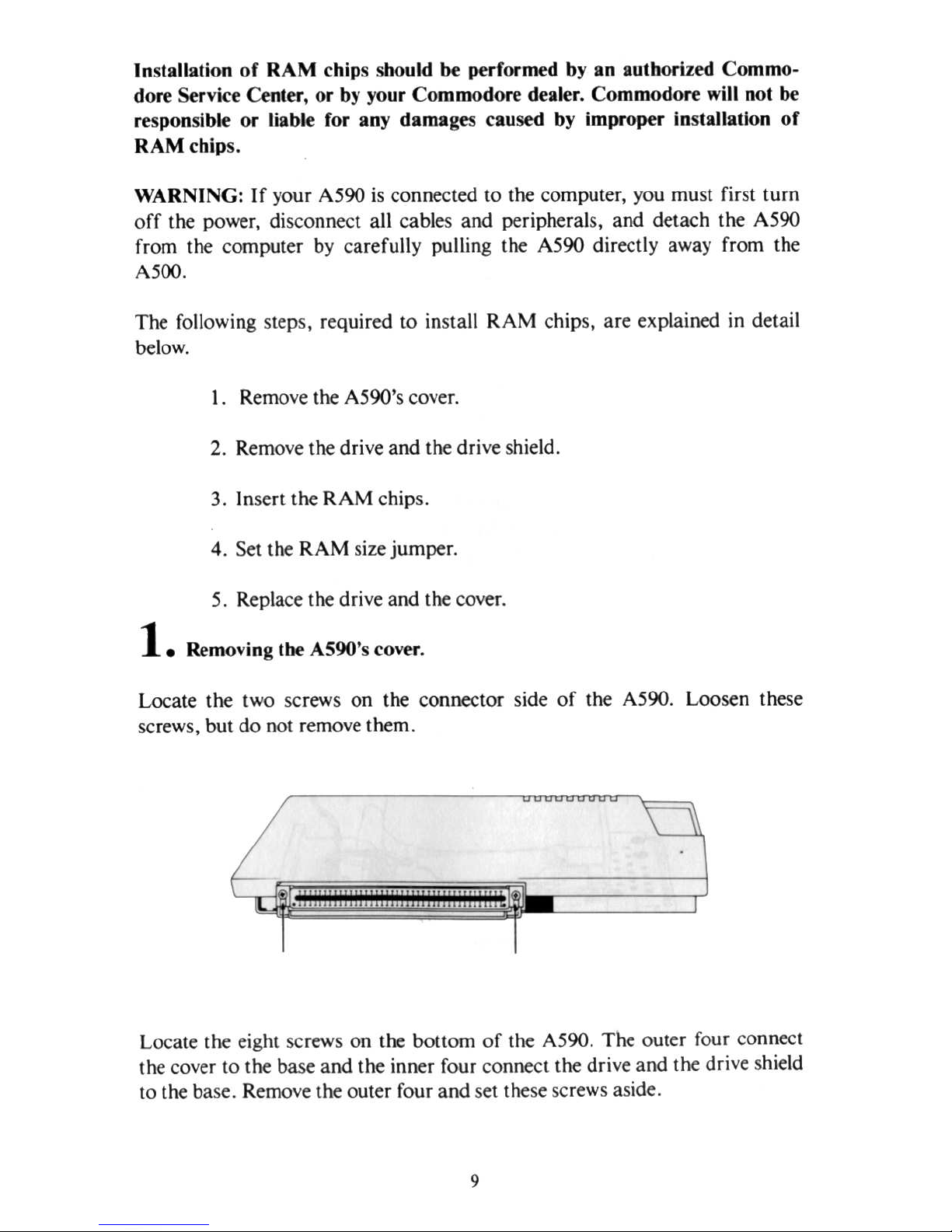
1.
Removin
g t
he
AS90's cover.
Locate t
he
two screws on the connector side
of
the A590. Loosen these
sc
rews,
but
do
not
remove
them.
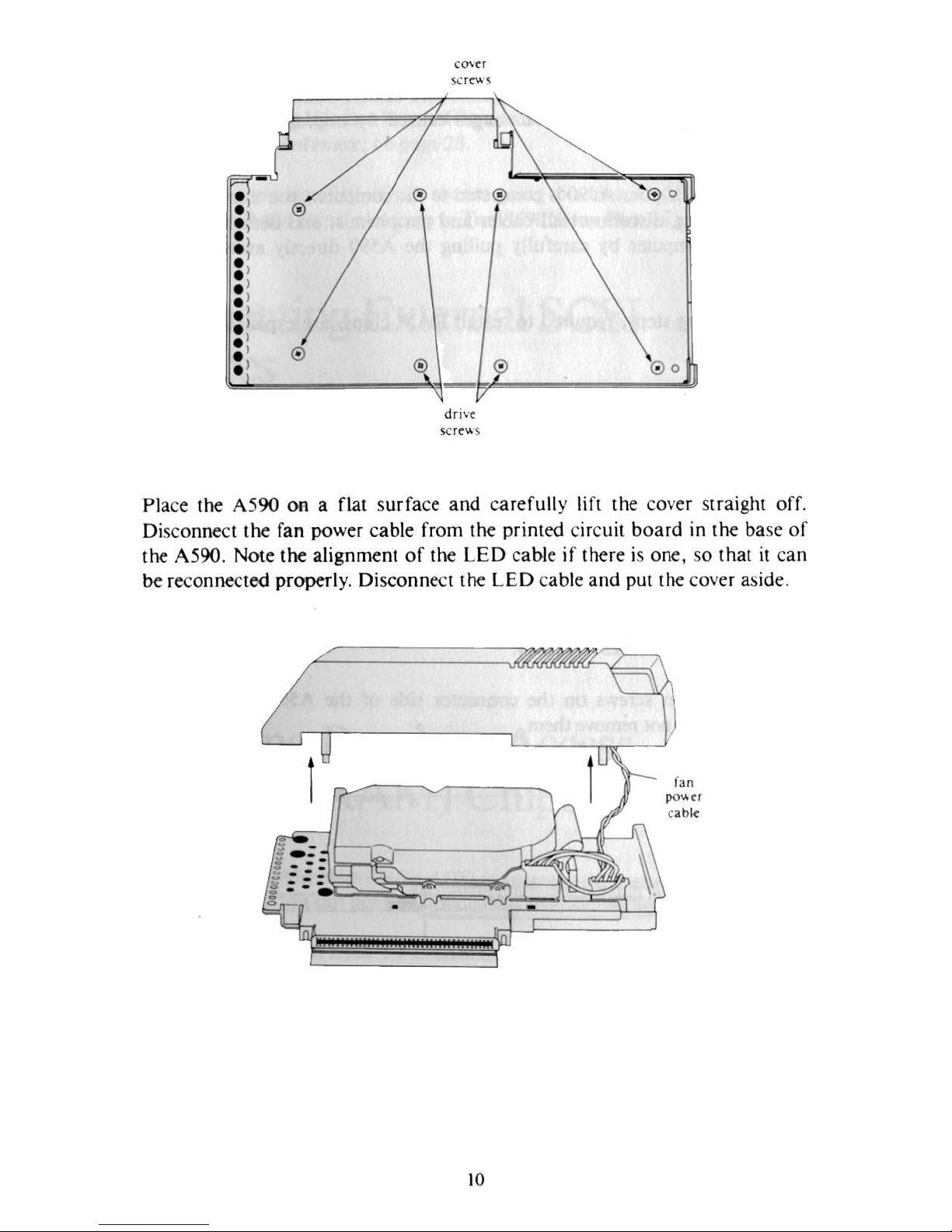
Loca te the eight screws on the bottom
of
the A590. The outer four connect
the cover to
the
base and the inner four connect the drive and
the
drive shield
to
the
base. Remove
the
outer
four
and
set
these screws aside.
9
•
® ®
®o
•
®
.,
.,
•
•
. )
.,
.,
.,
.,
.,
®
.,
®
•
• 0 0
-
drive
se
re
....
s
Place the A590 on a flat s
urfa
ce and car
efully lifl the cover straight ofr.
Disconnect the
fan
power cable from
the
printed circuit board in
the base
of
the A590.
NOle
lhe alignment of the
LED cable if
the
re
is one, so that
it
can
be reconnected properl
y. Disconnect the
LED cab
le and put the cover aside.
10
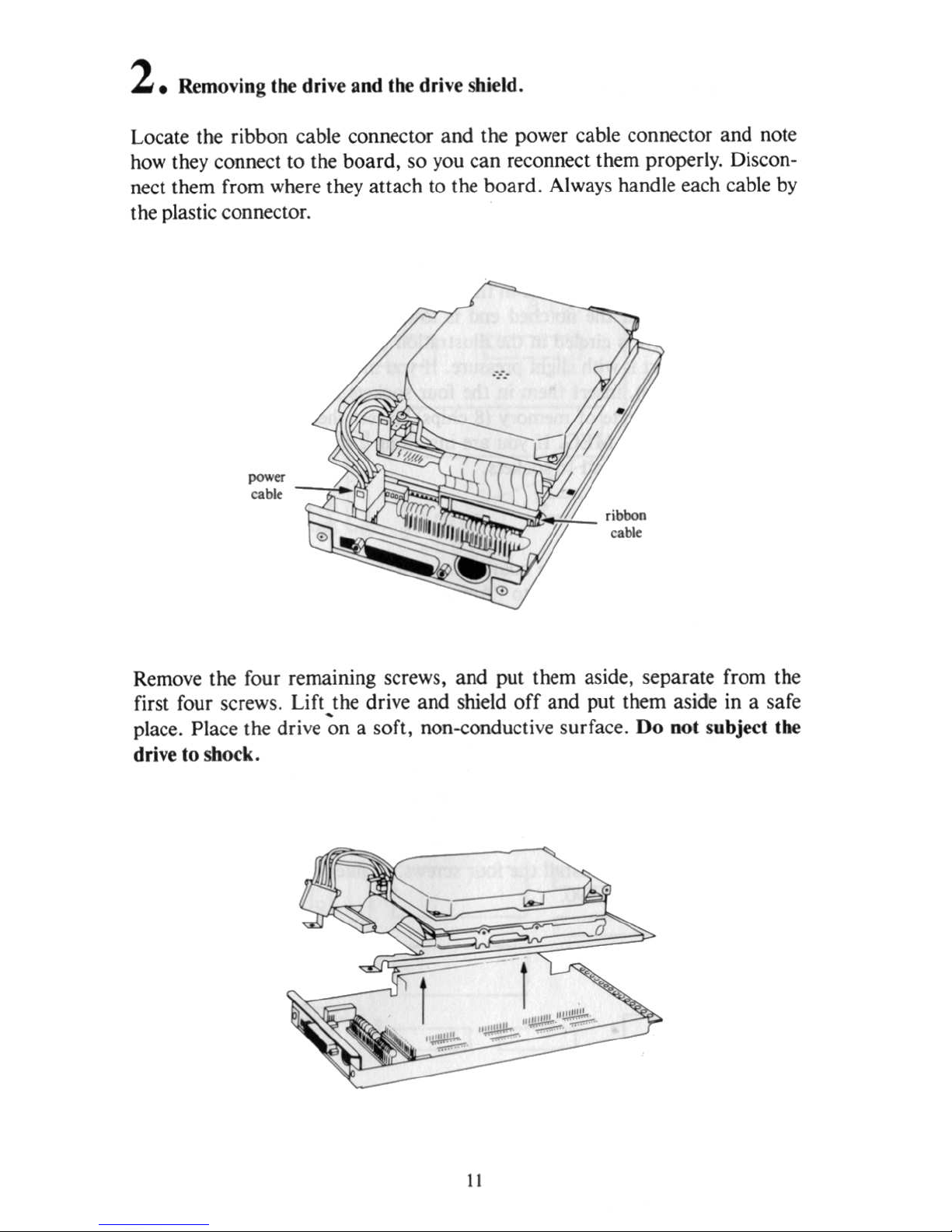
2. Removing
th
e drive and the drive shield.
Locate the ribbon cable connector and the power cable connector and note
how
they connect to the boa rd, so
you
can reconnect them properly. Discon-
nect them from where they attach to the board . Always handle each ca
ble
by
the plastic connector.
Remove the four remaining screws, and put them aside, separate from the
first four screws. Lift ,the drive and shield
off
and put them aside in a safe
place. Place the drive on a soft, non-conduc
ti
ve
surface. Do not subjecl Ihe
d
ri
ve
10 shock.
I I
3. Inserling lhe
RAM
chip
s.
NOIe:
Be
careful
10
properly align lhe chips
hefor.
inserling
lhem.
Do
nol
force Ihem
or
bend lhe pins.
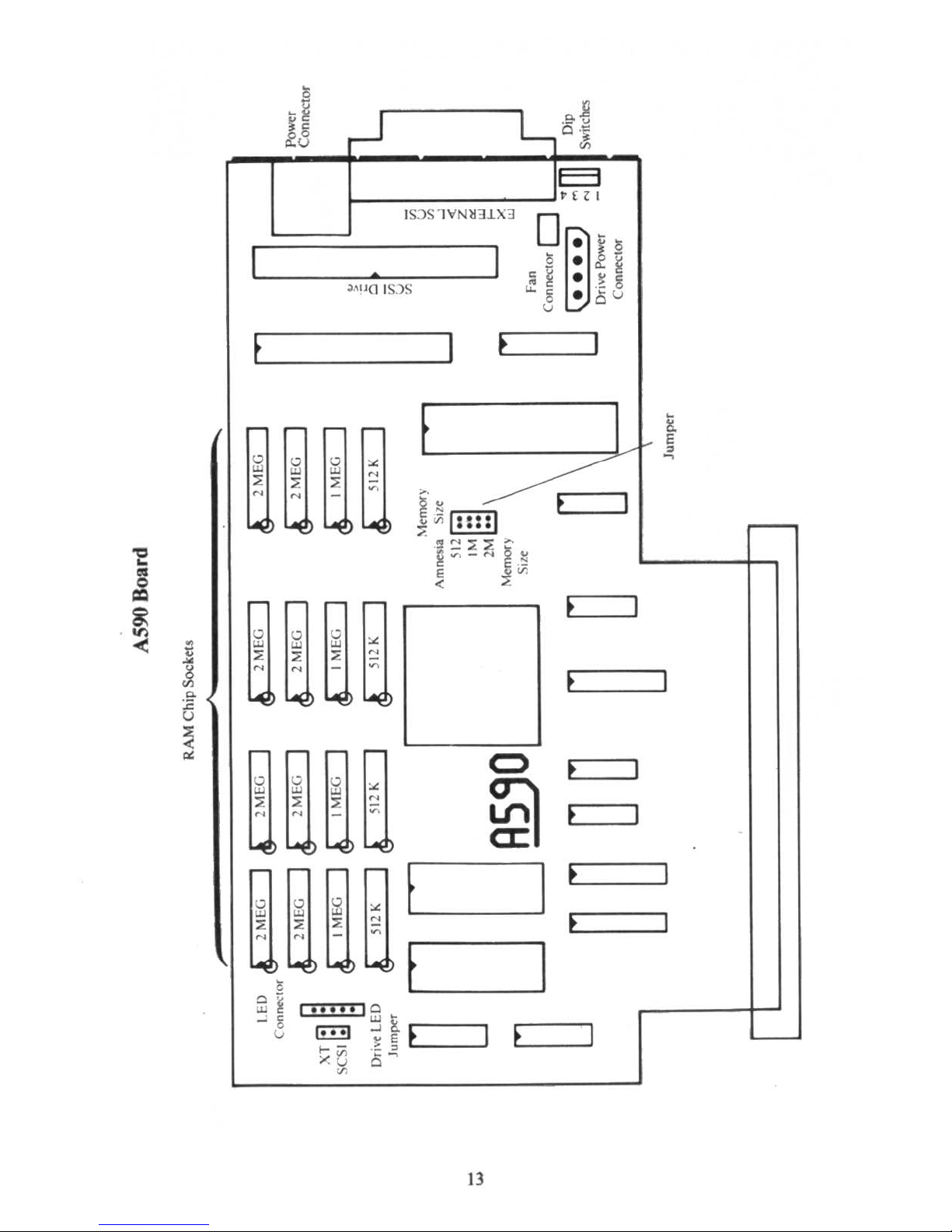
Turn
Ihe A590's
board
so Ihal
it
mat ches
the
illuslralion on
the
nexi page.
It
is
important
that
the chips be inserted properly. Each chip
has
a notch
or
dot
on one end to show the l
ocation
of
pin I.
When
the
end
with the notch
or
dot
is held to Ihe left, pin
I will be in the lower lefl
co
rner.
The
chip
should then
be
in
serted
so
that
the notched
end
is toward s the l
eft
of
the
board.
The
local ion for pin I is circled in the illustration below. Align the chip wit h Ihe
socket
and
insert
it with slight
pressur
e. I f you
are insta
lling 512 kilobyles
of
memory (4 chips), insert them in the four
soc
kets label
ed
SI2K. If you
are
installing I megabyte
of
memory
(8
chip
s), insert them in the eight sockets
labeled
St2K
and I MEG.
If
you
are
insta
lling 2 megabyt
es
of
memory (16
chips), insert Ihem in all
16
soc
kets.
4. Selling lhe
jumper.
You
must se l a
jumper
on
Ihe
board
10
match Ihe
amount
of
RAM
inSlalied.
As shipped. the
jumper
is set to
"Amn
esia" ,
or
no
RAM
installed. Lift Ihe
jumper
straight
off
and
replace it on the set
of
pins labeled the same as Ihe
amount
of
RAM
inslalled .
S.
Replacing lhe drive and
the
cove
r.
Replace
the
drive and the drive shield . Reconnect the
ribb
on
cab
le
and
Ihe
power ca ble .
Make
certain
that the connectors
and
the pins are aligned prop-
erly.
The
power
cab
le connec tor is s
haped
so that
it can
only fit the correct
way.
Replace the four Screws to hold the dri
ve
and
shield in place. Reconneci
the fan's power cable to
the board
. Reconnect the
LED
cab
le if there
is
one.
Replace Ihe cover
and
install
the
four screws. Tighten the two screws
on
the
conneclOr side
of
the A590.
t2
•
k~
-=
i5~
E:I
HZ
I
I
S:1S
IVNMJ1>..3
°m
l
'
I
~
.
~
I
:;~.~g
J,\U
~
IS.
)S
t....
g •
aU
u
f
I
E
I
•
!l
E
r
r
.;:
I I
II
I I
-
~
cO
cO
-<
I
8
...
N
U
~
~
,.
..
-
~
~
[ill)
N
N
...
J'l
••••
'"'I!l
:;::
-"
~
-
-
!P"L~'j"
~
~~-
....
;;
E
<
I I
I
I
I
~
I
cO
~
-<
v
N
...
~
~
•
~
~
"
~
I
~
~
-
N
N
'*
~
is
~--
-
~
:>:
<
f I
0
r
I .
I
I
~
I
"
E
v
:,]
.<
<>
'"
N
W
~
~
"
< .
N
-
N
I
:'
-~
~
~
f
l
f
f I
I I Iv 1
.<
I
"8U.1
...
,
I
.;J~~;;
~-
.
~J
~
- - f
,
-Q
F I
"
~
I
•••
'II
~~
I
::
.
E!:!l
~
E f
v
-,
1-;;;
.5-
"u
~
13

Using
the
Hard
Disk
This manual assumes that
you
are familiar with the operation
of
the Amiga
500
as described
in
the Introduction to the Amiga
500
manual.
The device name
of
the A590, as shipped,
is
DH9:. The partition on the A590
is
Workbench:.
It
contains the directories and files that are on the Workbench
and the Extras diskettes.
The Workbench partition is formatted using the Fast File System (FFS). The
Fast File System
is
solely
for use
with a hard drive system.
It
differs from the
standard
fi
le system in that
it
increases data transfer speed a
nd
allows more
data to be stored on the disk. For more details on FFS, see Appendix A
of
the
1.3 Enhancer manual.
WARNING:
To
protect the A590, always park
Ihe
drive heads before turning
your system off.
To
park Ihe drive heads, locate Ihe Park icon on the A590
Setup
di
sk, and double click on il. Always wait thirty seconds before lurning
the
sys
tem
off.
Copying
Programs
to
Your
Hard
Disk
Ip addition to working with the utilities on Workbench and Extras,
you
will
wanl to transfer other software programs to your hard disk. Note thai most
commercial software packages have instructions
for
installing ·the
sof
tware
on the hard disk.
This section demonstrates how to copy a generic software program
to
your
hard drive. Since this procedure involves Ihe CLl/ SHELL and some basic
AmigaDOS commands,
you
should refer to Chapter 7
of
the Introduction
manual if
you
are not familiar with using the
CLl.
t 5
 Loading...