

Commodore Amiga A1200 User Manual
User's
Guide
A1200
AM/CA
(:: Commodore

User's
Guide
A1200
Copyright © 1992 by Commodore Electronics Limited. All rights Reserved. This document may not, in
whole or
in
part, be copied, photocopied, reproduced, translated or reduced to any electronic medium or
machine readable form without prior consent,
in
writing, from Commodore Electronics Limited.
With this document Commodore makes no warranties or representations, either expressed, or implied,
with respect to the products described herein. The information presented herein
is
being supplied on an
"AS IS" basis and
is
expressly subject
to
change without notice. The entire risk as to the use of this
information is assumed by the user.
IN
NO
EVENT WILL COMMODORE
BE
LIABLE FOR ANY
DIRECT, INDIRECT, INCIDENTAL, OR CONSEQUENTIAL DAMAGES RESULTING FROM ANY
CLAIM ARISING
OUT
OF THE INFORMATION PRESENTED HEREIN, EVEN IF IT HAS BEEN
ADVISED OF THE POSSIBILITIES OF SUCH DAMAGES. SOME STATES DO NOT ALLOW THE
LIMITATION OF IMPLIED WARRANTIES OR DAMAGES, SO THE ABOVE LIMITATIONS MAY NOT
APPLY.
Commodore and the Commodore logo are registered trademarks of Commodore Electronics Limited.
Amiga
is
a registered trademark, and AmigaDOS, Bridgeboard, Kickstart, and Workbench are
trademarks, of Commodore-Amiga, Inc. Hayes
is
a registered trademark of Hayes Microcomputer
Products, Inc. Centronics
is
a registered trademark of Centronics Data Computer Corp. Motorola is a
registered trademark, and 68030 and 68EC020 are trademarks, of Motorola Inc. MultiSync
is
a
registered trademark of NEC Technologies Inc. ARexx
is
a trademark of William
S.
Hawes. MS-DOS
is
a registered trademark of Microsoft Corporation.
NOTE: This equipment has been tested and found
to
comply with the limits for a Class B digital device,
pursuant to Part 15 of FCC Rules. These limits are designed
to
provide reasonable protection against
harmful interference
in
a residential installation. This equipment generates, uses and can radiate radio
frequency energy and, if not installed and used according with the instructions, may cause harmful
interference to radio communications. However, there
is
no guarantee that interference will not occur
in
a particular installation. If this equipment does cause harmful interference to radio or television
reception, which can be determined by turning the equipment off and on, the user
is
encouraged to try
to correct the interference
by
one or more of the following measures:
• Reorient or relocate the receiving antenna.
• Increase the separation between the equipment and the receiver.
• Connect the equipment into
an
outlet
on
a circuit different from that to which the receiver
is
connected.
• Consult the dealer or
an
experienced radiorrV technician for help.
CAUTION: Only equipment with shield-grounded cables (computer input-output devices, terminals,
printers, etc.) certified to comply with appropriate FCC limits can be attached to this device.
Operation with non-certified equipment may result
in
communications interference. Changes or
modifications not expressly approved by the party responsible for compliance could void the
user's authority to operate the device.
This digital apparatus does not exceed the Class B electromagnetic noise emission limits for digital
apparatus as defined
in
the radio interference regulations of the Canadian Department of
Communications.
Le present appareil numerique n'emet pas de bruits radioelectriques depassant les limites applicables
aux appareils numeriques de Classe B prescrites dans le reglement sur le brouillage radioelectriques
edicte par le Ministere des Communications du Canada.
Printed in Germany, Hong Kong, the Philippines, Singapore, Taiwan and the United Kingdom.
This book was produced using a variety
of
Commodore systems by Ross
Hippely, Wilson Harp, and Carina Ahren,
PIN:
368997-01
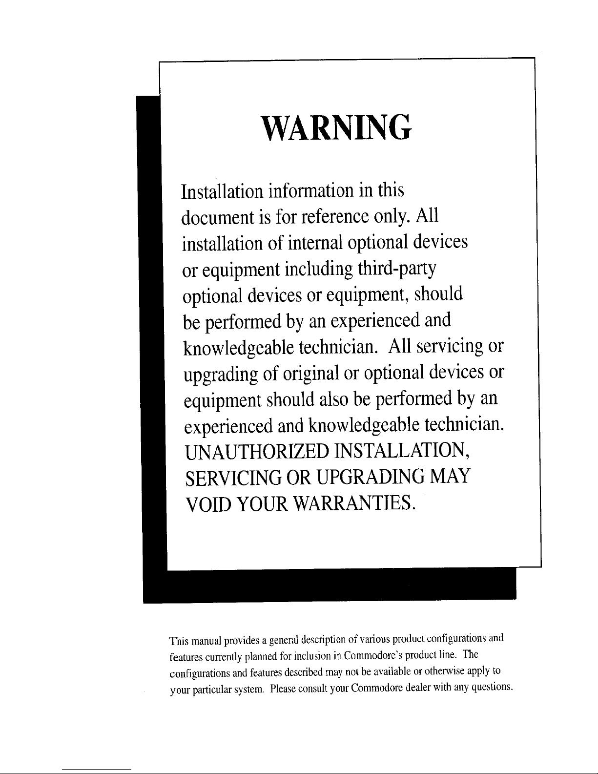
WARNING
Installation
information
in
this
document
is
for
reference
only.
All
installation
of
internal
optional
devices
or
equipment
including
third-party
optional
devices
or
equipment,
should
be
performed
by
an
experienced
and
knowledgeable
technician.
All
servicing
or
upgrading
of
original
or
optional
devices
or
equipment
should
also
be
performed
by
an
experienced
and
knowledgeable
technician.
UNAUTHORIZED
INSTALLATION,
SERVICING
OR
UPGRADING
MAY
VOID
YOUR
WARRANTIES.
This
manual
provides a general
description
of
various
product
configurations
and
features
currently
planned
for
inclusion
in
Commodore's
product
line.
The
configurations
and
features
described
may
not
be
available
or
otherwise
apply
to
your
particular
system.
Please
consult
your
Commodore
dealer
with
any
questions.
Table
of
Contents
Chapter 1
Quick Connect
Before You Begin ............................................................................ 1-1
As You Set Up Your System ........................................................... 1-1
Main
Unit
.......................................................................................... 1-2
Attaching the Mouse ............................................................................. 1-5
Attaching a Monitor .............................................................................. 1-6
RGB Monitors ................................................................................ 1-6
Composite Monitors ....................................................................... 1-7
NTSC Televisions .......................................................................... 1-7
PAL Televisions ............................................................................. 1-9
SCART Televisions ...................................................................... 1-10
Connecting Optional Equipment .................................................. 1-1 0
Audio Connection ............................................................................... 1-10
Audio Connection to a Stereo Monitor ..........................................
1-11
Audio Connection to a Monaural Monitor ......................................
1-11
Audio Connection to Other Equipment .........................................
1-11
Attaching
an
External Floppy Drive ..................................................... 1-12
Attaching a Parallel Device ................................................................. 1-12
Attaching a Serial Device .................................................................... 1-12
Attaching a Joystick ............................................................................ 1-12
Connecting Power and Turning On the
Amiga
............................ 1-13
vi
Table
of
Contents
Chapter
2
Getting Started
Booting
Floppy-Based Systems .....................................................
2-1
Booting
Hard Disk-Based Systems ................................................
2-1
The
Opening
Screen ....................................................................... 2-2
Turning
Off
the
Amiga .................................................................... 2-3
The
Amiga
Keyboard ....................................................................... 2-3
The Main Keyboard Area ...................................................................... 2-5
Shift Keys ...................................................................................... 2-5
Alt Keys ......................................................................................... 2-5
Ctrl ................................................................................................ 2-6
Left Amiga .....................................................................................
2~6
Right Amiga ................................................................................... 2-6
Return ........................................................................................... 2-6
Caps Lock ..................................................................................... 2-6
Esc ................................................................................................ 2-7
Tab ................................................................................................ 2-7
Backspace ..................................................................................... 2-7
The Numeric Keypad ............................................................................ 2-7
The Function Keys ................................................................................ 2-8
The
Del,
Help, and Arrow Keys ............................................................. 2-8
Del
................................................................................................. 2-8
Help ............................................................................................... 2-8
The Arrow Keypad ......................................................................... 2-8
Keyboard Equivalents to the Mouse ....................................................... 2-9
Chapter 3
Before Expanding Your System
Memory
Expansion
.........................................................................
3-1
Drive Expansion ................
~.;
........................................................... 3-2
CPU
Expansion ............................................................................... 3-2
PCMCIA Expansion ......................................................................... 3-2
When
Installing
Internal Options ................................................... 3-3
ESD Precautions .................................................................................. 3-4
Table
of
Contents vii
Chapter 4
Using PCMCIA Cards
Inserting and Removing Card Slot Devices ...................................
4-1
Memory Cards .................................................................................. 4-2
Write-Protection ................................................................................... 4-2
Card Battery ............................................................................ , ............ 4-3
Cards Prepared as RAM ....................................................................... 4-3
Cards Prepared as Disk ........................................................................ 4-3
ROM Applications ............................................................................ 4-4
Other Devices .................................................................................. 4-4
Notes on Insertion and Removal .................................................... 4-4
Chapter 5
Help With System Problems
Avoiding Problems ..........................................................................
5-1
Identifying and Solving Problems .................................................. 5-2
Software Problems ............................................................................... 5-2
Startup Problems .................................................................................. 5-3
Disk Problems ...................................................................................... 5-4
Notes
on
Floppy-Based Systems ................................................... 5-4
Notes
on
Hard Disk Systems ......................................................... 5-4
Installation and Maintenance Problems ................................................. 5-5
Installation Problems ..................................................................... 5-6
Maintenance Problems .................................................................. 5-6
Non User-Serviceable Problems ..................................................... 5-6
Appendix A
Technical Specifications
viii
Table
of
Contents
AppendixB
Input/Output Connector Pin
Assignments
SERIAL Port •...................................................................................
8-2
PARALLEL
Port
..............................................................................
8-4
VIDEO Port ......................................................................................
8-6
MOUSE Ports .................................................•................................
8-8
DISK DRIVE
(floppy)
Port ...............................................................
8-9
CPU
Slot
........................................................................................ 8-10
AppendixC
Using Floppy Disks
Using 3.S-lnch Floppy Disks ..........................................................
C-1
Guidelines
for
Using Disks ............................................................ C-3
AppendixD
Amiga Character Set
Index
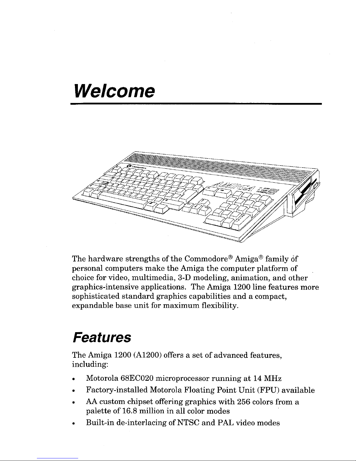
Welcome
The
hardware
strengths
ofthe
Commodore® Amiga® family
cif
personal
computers
make
the
Amiga
the
computer
platform
of
choice for video,
multimedia,
3-D mode ling,
animation,
and
other
graphics-intensive
applications.
The
Amiga
1200 line
features
more
sophisticated
standard
graphics
capabilities
and
a compact,
expandable
base
unit
for
maximum
flexibility.
Features
The
Amiga
1200 (A1200) offers a
set
of
advanced
features,
including:
• Motorola 68EC020 microprocessor
running
at
14
MHz
•
Factory-installed
Motorola
Floating
Point
Unit
(FPU)
available
• AA
custom
chipset
offering
graphics
with
256 colors from a
palette
of
16.8 million
in
all color
modes
•
Built-in
de-interlacing
ofNTSC
and
PAL video
modes
x Using this Guide
• Up to 2 megabytes 32-bit "Chip"
memory
• IDE (16-bit)
hard
drive interface
• Optional
internaI2.5-inch
hard
drive
•
Integral
full-size keyboard
with
numeric
keypad
• PCMCIA "credit card" memory/accessory slot
•
Internal
150-pin "local bus" CPU slot
•
Expandable
to 8 megabytes "Fast" memory
• RGB, color composite,
and
RF
(television)
outputs
• Built-in 880
KB
floppy disk drive
• Four-voice stereo sound
output
Using this Guide
This
guide is designed to help you
set
up
your
Amiga
system
quickly
and
safely.
It
contains information on
making
the
necessary
external
connections,
adding
internal
and
external
expansion
options,
and
other
hardware-related
tasks.
Once your Amiga
system
is
up
and
running
properly, you
should
be able to
put
this
manual
aside
until
such
time
as
you
add
expansion
hardware
or
need
technical information.
Consult
the
other
Amiga documentation included
with
your
system
for software information.
DocumentConvenHons
In
this
and
other
Amiga documentation from Commodore,
the
following conventions
are
used:
Amiga, A1200 The Amiga 1200
main
unit
is
usually
referred
to
as
the
A1200 or
the
Amiga.
Key1 + Key2 Key combinations
with a plus
(+) sign
between
the
keys indicate
pressing
the
keys simultaneously.
For
example, Right Amiga+O
means
to hold down
the
rIght Amiga
key
and,
while holding
it
down,
press
O.
Related Documentation
xi
Amigakeys
These
two keys
on
the
Amiga
keyboard
are
used
for
special functions.
The
left
Amiga
key
is
to
the
left
of
the
space
bar
and
is
marked
with a large
solid
A.
The
right
Amiga
key
is
to
the
right
of
the
space
bar
and
is
marked
with
an
outlined
A.
Unlike
Shift
and
Alt
key
pairs,
the
two
Amiga
keys
usually
have
different
functions.
Enter
Directions to "enter"
something
mean
to
type
in
the
indicated
information
and
then
press
Return.
arrow
keys
The
arrow
keys
are
the
four
keys
in
an
inverted-
T
formation
to
the
right
of
the
main
keyboard,
with
arrows
on
them
pointing
up,
down, left,
and
right.
Do
not
confuse
these
keys
with
others
on
the
keyboard
marked
with
arrows.
Related Documentation
•
•
•
•
Workbench™ User's Guide
AmigaDOSTM User's Guide
ARexx
User's Guide
The
Amiga
Hard
Drive User's Guide
If
you
come
upon
terms
in
this
book
that
you do
not
understand,
look
in
the
Glossary
of
the
Workbench User's Guide,
which
defines
many
computer
and
Amiga-specific
terms.

1
1
1
1
1
1
1
1
1
1
1
1
1
1
1
1
1
1
1
1
1
1
1
1
1
1
1
1
1
1
1
1
1
1
1
1
1
1
1
1
1
Chapter 1
Quick Connect
As
you
unpack
your
system,
check
the
items
in
the
system
box.
Contact
your
dealer
immediately
if
anything
is
damaged.
This
chapter
guides
you
through
setting
up
your
system.
Read
the
instructions
carefully.
Before
You
Begin
•
Choose
a location for
your
system
away
from
heat,
dust,
smoke,
vibration
and
electrical
interference.
•
Choose a stable
work
surface
at
least
6 in.l15
cm
away
from a
wall.
•
Have
on
hand a multi-outlet
power
strip
with
surge
protection.
(These
units
are
available
from
most
computer
stores.)
Commodore
strongly
recommends
that
you
use
this
type
of
outlet
to
protect
your
system
from
electrical
problems.
•
Make
sure
your
equipment
matches
the
electrical
requirements
for
the
country
in
which
you
are
using
the
computer.
For
example,
you
can't
use
a 110/115
volt
model
in
countries
having
a 220/240
volt
system.
•
Read
the
descriptions
in
this
chapter
to
acquaint
yourself
with
the
purpose
and
function
of
each
feature
and
connector.
As
You Set
Up
Your System
•
If
possible,
plug
your
system
into a separate
circuit
to
avoid
any
electrical
interference.
Voltage
surges
and
drops
caused
by
1-2
Main Unit
devices
such
as
air
conditioners,
fans
and
vacuum
cleaners
can
cause
damage
to
your
computer
data
and/or
to
the
computer
itself.
• Look
at
your
system
and
match
the
features
and
connectors
with
the
illustrations
in
this
chapter.
Use
the
illustrations
to
help
you
identify
the
lights, switches, connectors
and
disk
drive.
•
Use
the
instructions
to connect
the
monitor,
mouse,
and
any
optional
peripherals
to
the
system
unit.
All connectors
are
shaped
so
they
fit only one way.
Don't
try
to force a cable
into
a
connector.
•
Never
connect
or
disconnect
any
equipment
when
the
system
power
is
on!
•
If
you
have
a problem,
always
check
the
instructions
before
proceeding,
especially
the
illustrations.
Remember,
you
can
cause
damage
by
not
following
instructions.
Main Unit
The
main
unit
case
contains
the
basic
components
that
run
your
computer.
The
system
motherboard,
disk
drives,
and
optional
expansion
module
are
located
in
the
main
unit.
Most
other
parts
of
your
computer
system
connect to
the
main
unit
by
cables.
The
top
panel,
illustrated
in
Figure
1-1,
identifies
system
features
such
as
the
keyboard
and
disk
drive
activity
lights.
The
right
side
panel,
illustrated
in
Figure
1-2, shows
the
floppy
drive
slot
and
disk
eject
button.
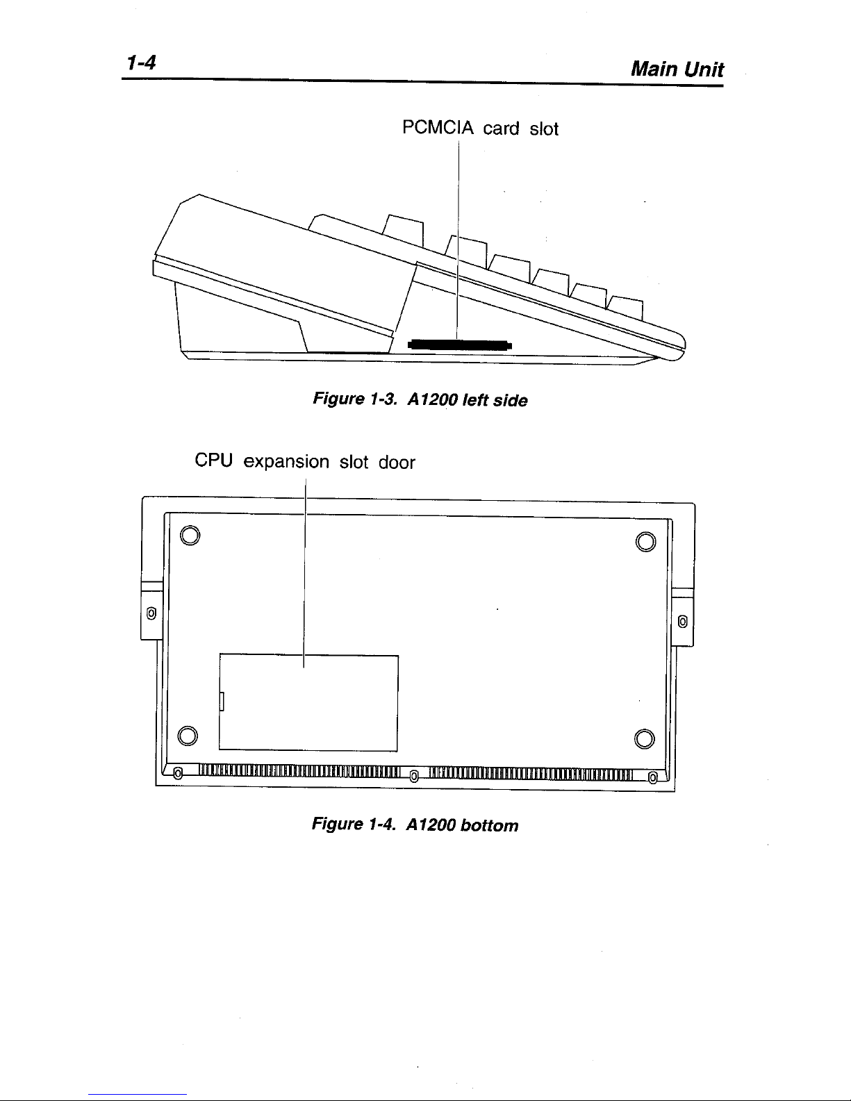
The
left
side
panel,
illustrated
in
Figure
1-3,
shows
the
PCMCIA
card
slot.
The
bottom
panel,
illustrated
in
Figure
1-4,
shows
the
location
of
the
CPU
expansion
slot door.
The
rear
panel,
illustrated
in
Figure
1-5,
shows
you
where
the
other
parts
of
your
system
(for example,
the
monitor
and
mouse)
plug
into
the
main
unit.
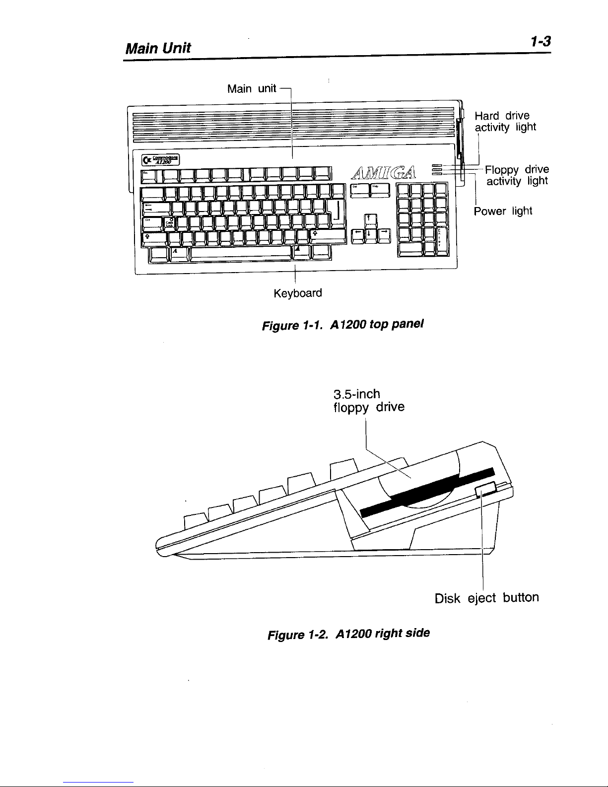
Main Unit
Main unit
Keyboard
Figure
1-1.
A 1200
top panel
3.5-inch
floppy
drive
~
Figure
1-2.
A1200 right side
1-3
Hard drive
activity light
--+-rt--Floppy
drive
activity light
Disk eject button
1-4
Main Unit
PCMCIA card slot
Figure 1-3. A 1200 left
side
CPU
expansion slot door
0
0
I--
-
I--
-
@
@
L-
r-
0
0
-IOJ-
J(jI11mm11l1l1mHR11
111111111801
0
Figure 1-4. A 1200
bottom
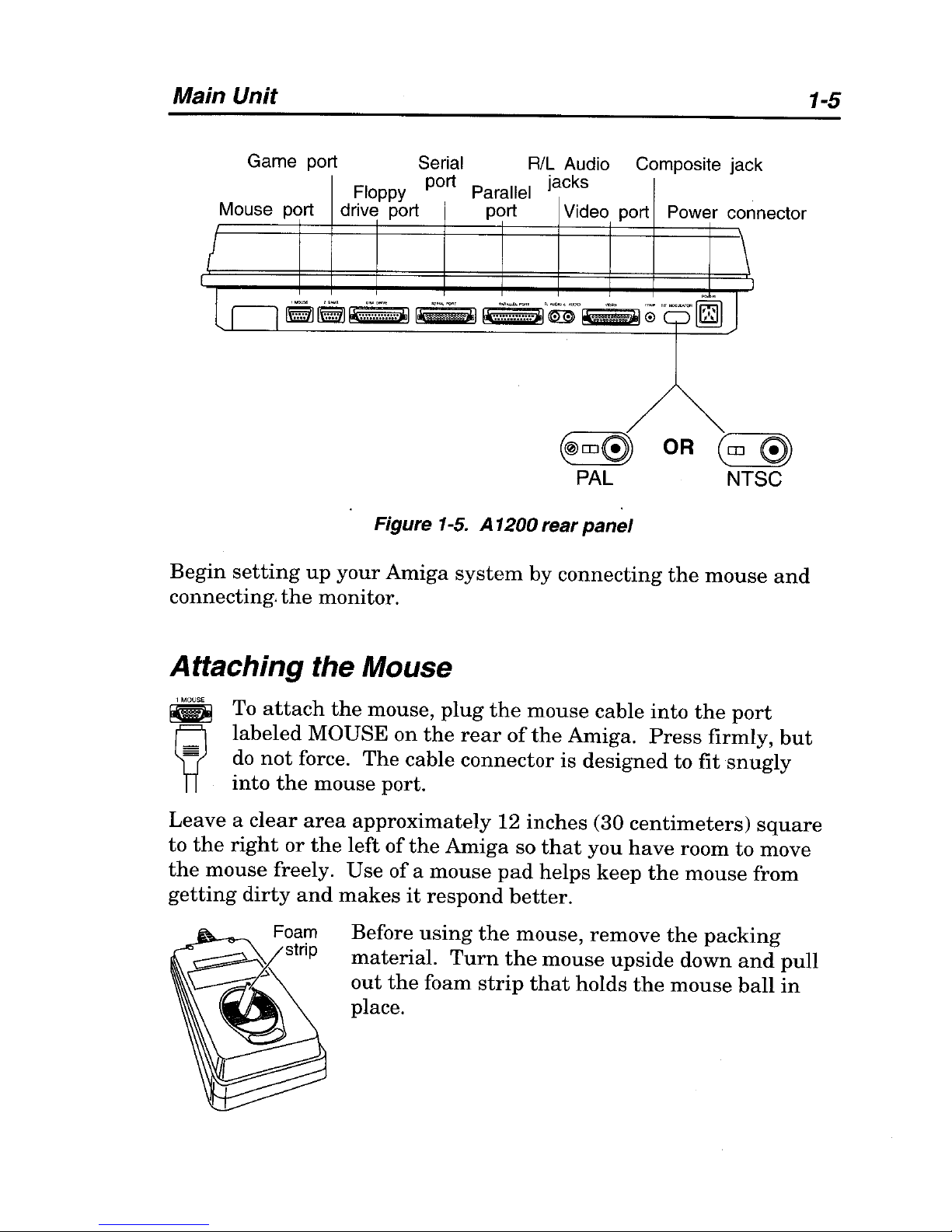
Main Unit
1-5
Game port
Serial
R/L
Audio Composite jack
Floppy
port
Parallel
jacks
Mouse
port drive
port
port
Video port Power con nector
!
\
le"
J
Cl
~rE1J!li·::'~::~:j"".1
~
!ll.:.~:;.::~;;
..
Ai9°~ 0 "'-~-~
~m0
OR
Cm
0
PAL
NTSC
Figure 1-5. A 1200 rear
panel
Begin
setting
up
your
Amiga
system
by
connecting
the
mouse
and
connecting.
the
monitor.
Attaching the Mouse
~
To
attach
the
mouse,
plug
the
mouse
cable
into
the
port
labeled
MOUSE
on
the
rear
of
the
Amiga.
Press
firmly,
but
do
not
force.
The
cable
connector
is
designed
to
fit
snugly
into
the
mouse
port.
Leave a clear
area
approximately
12
inches
(30
centimeters)
square
to
the
right
or
the
left
of
the
Amiga
so
that
you
have
room
to
move
the
mouse
freely.
Use
ofa
mouse
pad
helps
keep
the
mouse
from
getting
dirty
and
makes
it
respond
better.
Before
using
the
mouse,
remove
the
packing
material.
Turn
the
mouse
upside
down
and
pull
out
the
foam
strip
that
holds
the
mouse
ball
in
place.
1-6 Main Unit
Attaching a Monitor
The
A1200
has
three
display
outputs,
allowing you to
use
any
of
several
kinds
of
display
devices:
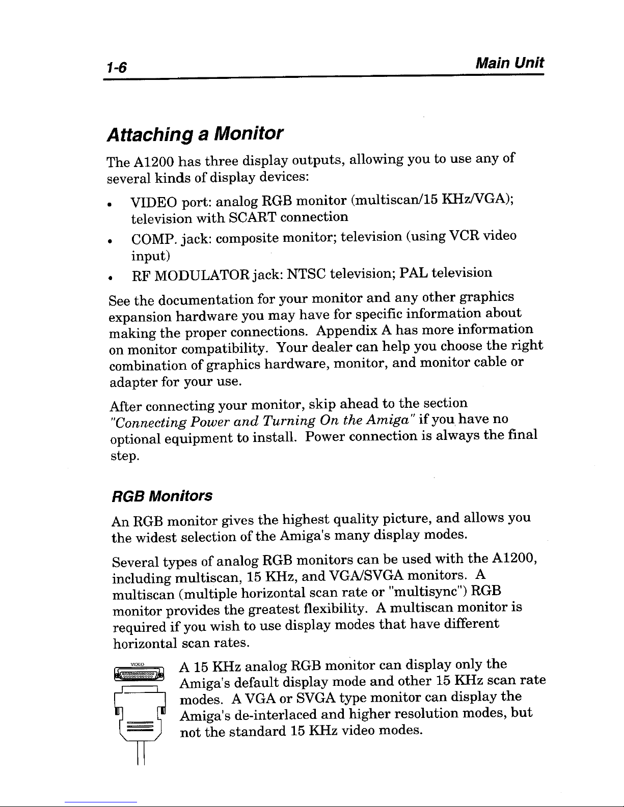
• VIDEO port:
analog
RGB
monitor
(multiscanl15
KHzNGA);
television
with
SCART connection
• COMP.
jack:
composite monitor;
television
(using
VCR video
input)
RF MODULATOR jack: NTSC television;
PAL
television
See
the
documentation
for
your
monitor
and
any
other
graphics
expansion
hardware
you
may
have
for
specific
information
about
making
the
proper
connections.
Appendix A has
more
information
on
monitor
compatibility.
Your
dealer
can
help
you choose
the
right
combination
of
graphics
hardware,
monitor,
and
monitor
cable
or
adapter
for
your
use.
After
connecting
your
monitor,
skip
ahead
to
the
section
"Connecting Power
and
Turning
On the
Amiga"
if
you
have
no
optional
equipment
to
install.
Power
connection
is
always
the
final
step.
RGB Monitors
An RGB
monitor
gives
the
highest
quality
picture,
and
allows
you
the
widest
selection
of
the
Amiga's
many
display
modes.
Several
types
of
analog
RGB
monitors
can
be
used
with
the
A1200,
including
multiscan,
15 KHz,
and
VGAlSVGA monitors. A
multiscan
(multiple
horizontal
scan
rate
or
"multisync") RGB
monitor
provides
the
greatest
flexibility. A
multiscan
monitor
is
required
if
you
wish
to
use
display
modes
that
have
different
horizontal
scan
rates.
A 15 KHz
analog
RGB
monitor
can
display
only
the
Amiga's
default
display
mode
and
other
15 KHz
scan
rate
modes. A VGA
or
SVGA
type
monitor
can
display
the
Amiga's
de-interlaced
and
higher
resolution
modes,
but
not
the
standard
15 KHz video modes.
Main Unit
1-7
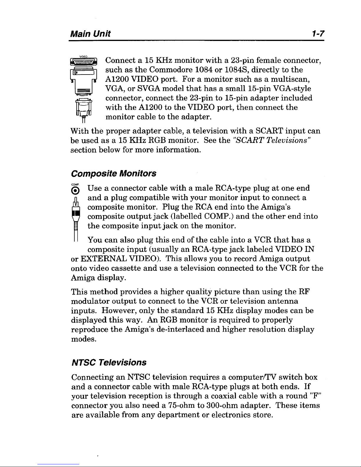
Connect
a 15 KHz
monitor
with
a 23-pin
female
connector,
such
as
the
Commodore 1084
or
10848,
directly
to
the
A1200
VIDEO
port.
For a monitor
such
as a multiscan,
VGA,
or
8VGA model
that
has a small
15-pin VGA-style
connector, connect
the
23-pin to 15-pin
adapter
included
with
the
A1200 to
the
VIDEO
port,
then
connect
the
monitor
cable
to
the
adapter.
With
the
proper
adapter
cable, a television
with
a SCART
input
can
be
used
as
a 15
KHz
RGB monitor. See
the
"SCART
Televisions"
section
below for
more
information.
Composite Monitors
o
Use a connector
cable
with a male
RCA-type
plug
at
one
end
~
and a plug
compatible
with
your
monitor
input
to
connect
a
composite
monitor.
Plug
the
RCA
end
into
the
Amiga's
composite
output
jack
(labelled COMP.)
and
the
other
end
into
the
composite
input
jack
on
the
monitor.
You
can
also
plug
this
end
of
the
cable
into
a VCR
that
has
a
composite
input
(usually
an
RCA-type
jack
labeled
VIDEO
IN
or
EXTERNAL
VIDEO).
This
allows you to record
Amiga
output
onto
video
cassette
and
use
a television connected to
the
VCR for
the
Amiga
display.
This
method
provides a higher
quality
picture
than
using
the
RF
modulator
output
to connect to
the
VCR
or
television
antenna
inputs.
However,
only
the
standard
15 KHz
display
modes
can
be
displayed
this
way.
An
RGB
monitor
is
required
to
properly
reproduce
the
Amiga's
de-interlaced
and
higher
resolution
display
modes.
NTSC Televisions
Connecting
an
NTSC
television
requires
a computerlTV
switch
box
and a connector
cable
with
male
RCA-type
plugs
at
both
ends.
If
your
television
reception
is
through
a coaxial cable
with a round
"F"
connector
you
also
need
a 75-ohm
to
300-ohm
adapter.
These
items
are
available
from
any
department
or electronics store.
1-8
Main Unit
If
you
have a VCR
or
television
set
with
a composite video
input
(an
RCAjack
usually
labeled
VID~O
IN)
you
should
use
the
composite
output
as
described
in
the
"Composite Monitors" section above.
This
is
simpler
and
produces a better
picture.
If
your
TV
or
VCR
has
antenna
inputs
only,
use
the
following
procedure:
1.
Disconnect
the
cable
or
VHF
antenna
wire
from
the
TV
or
VCR.
2.
For
coaxial cable:
connect
the
end
of
the
cable
to
a 75-ohm
to
300-ohm
adapter.
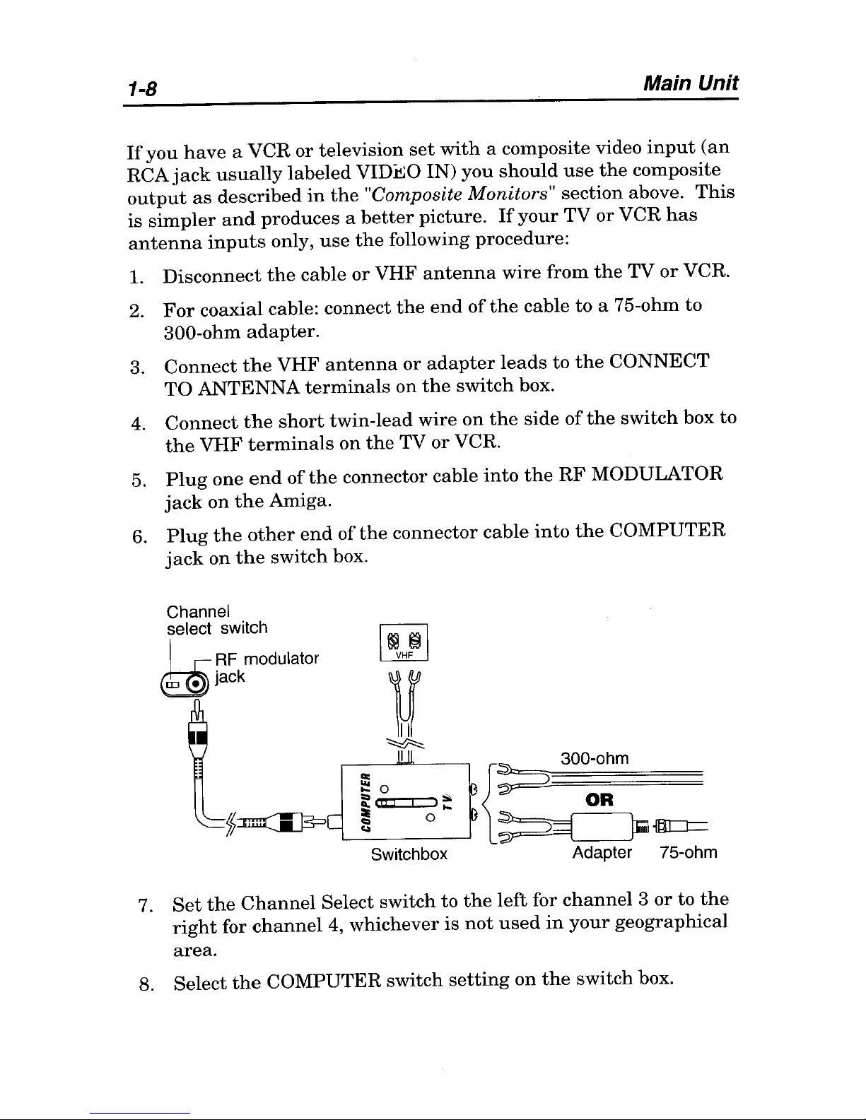
3.
Connect
the
VHF
antenna
or
adapter
leads
to
the
CONNECT
TO
ANTENNA
terminals
on
the
switch
box.
4.
Connect
the
short
twin-lead
wire
on
the
side
of
the
switch
box
to
the
VHF
terminals
on
the
TV
or
VCR.
5.
Plug
one
end
of
the
connector cable
into
the
RF
MODULATOR
jack
on
the
Amiga.
6.
Plug
the
other
end
of
the
connector cable
into
the
COMPUTER
jack
on
the
switch
box.
Channel
select switch
I
,-
RF
modulator
~jaCk
'" I
{~
300-ohm
~o
~
,(C!
I';:
OR
'---~
__
0----'
~
~
m=t=
Switch box
Adapter 7S-ohm
7.
Set
the
Channel
Select switch
to
the
left
for
channel 3 or
to
the
right
for
channel
4, whichever
is
not
used
in
your
geographical
area.
8.
Select
the
COMPUTER
switch
setting
on
the
switch
box.
Main Unit
1-9
Audio
output
from
the
Amiga
will
use
the
television's speaker(s).
You
may
also connect
the
Amiga
audio
outputs
as
described
in
the
"Audio Connection"
section.
PAL Televisions
If
you
have
a PAL VCR
or
television
set
with
a SCART
input,
see
the
"SCART
Televisions"
section below.
If
your
TV
or
VCR
has
a
composite video
input
(a
jack
usually
labeled
VIDEO
IN)
you
should
use
the
COMP.
output
as
described
in
the
"Composite Monitors"
section
above.
Either
of
these
methods
is
simpler
and
produces
a
better
picture
than
using
the
RF
MODULATOR
output.
Connecting
a
PAL
television
with
only
an
antenna
input
requires
a
connector
cable
with
a
male
RCA-type
plug
at
one
end
and
a
standard
75-0hm
PAL connector
at
the
other
end.
Use
the
following procedure:
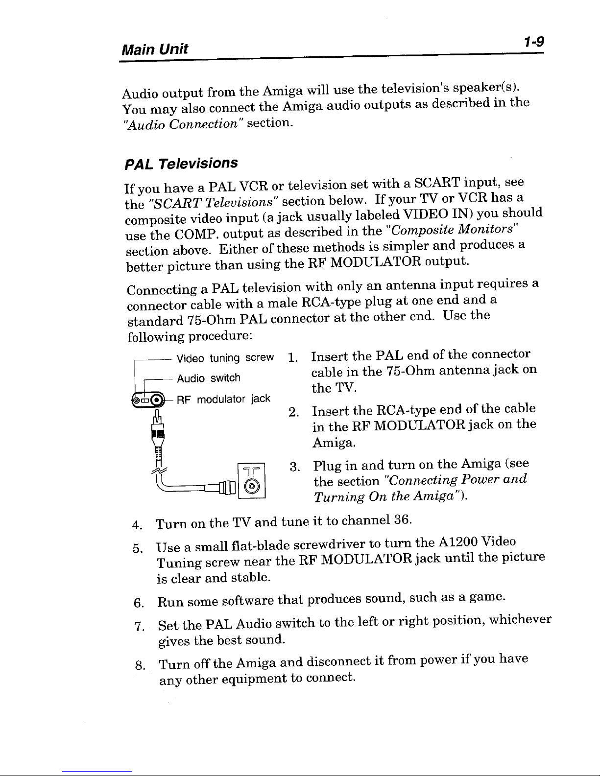
~
Video tuning screw
Audio switch
@jm.
RF
modulator jack
~
ll:::====r:!
=ill]
I
®
I
1.
Insert
the
PAL
end
of
the
connector
cable
in
the
75-0hm
antenna
jack
on
the
TV.
2.
Insert
the
RCA-type
end
of
the
cable
in
the
RF
MODULATOR
jack
on
the
Amiga.
3.
Plug
in
and
turn
on
the
Amiga
(see
the
section
"Connecting Power
and
Turning
On the
Amiga
").
4.
Turn
on
the
TV
and
tune
it
to
channel
36.
5. U
se
a
small
flat-blade
screwdriver
to
turn
the
A1200 Video
Tuning
screw
near
the
RF
MODULATOR
jack
until
the
picture
is
clear
and
stable.
6.
Run
some software
that
produces
sound,
such
as
a
game.
7.
Set
the
PAL
Audio
switch
to
the
left
or
right
position,
whichever
gives
the
best
sound.
8.
Turn
off
the
Amiga
and
disconnect
it
from
power
if
you
have
any
other
equipment
to connect.
1-10
Connecting Optional Equipment
Audio
output
from
the
Amiga will
use
the
television's speaker(s).
You
may
also connect
the
Amiga audio
outputs
as
described
in
the
"Audio Connection" section.
SCART
Televisions
Use
a SCARTIRGB
adapter
cable to connect
the
Amiga to
equipment
with
a SCART connector.
Insert
the
23-pin
end
of
the
cable
into
the
VIDEO
port
on
the
Amiga
and
the
RCA plugs
into
the
left
and
right
Amiga
audio jacks.
Insert
the
SCART connector
on
the
other
end
of
the
cable into
the
connector
on
the
equipment.
Audio
output
from
the
Amiga will use
the
television's speaker(s)
..
You
may
also connect
the
Amiga audio
outputs
as
described
in
the
"Audio Connection" section.
Note Since
the
definition of
the
SCART interface varies
somewhat
among TV
manufacturers,
consult
an
electronics or computer
dealer
to
get
the
proper
SCART
adapter
cable for
your
TV.
Connecting Optional Equipment
If
you
have
tested
your
Amiga system
after
making
the
basic
connections,
turn
it
off before connecting
any
other
items.
Never
attempt
to
connect or disconnect
anything
while
the
power
is
on.
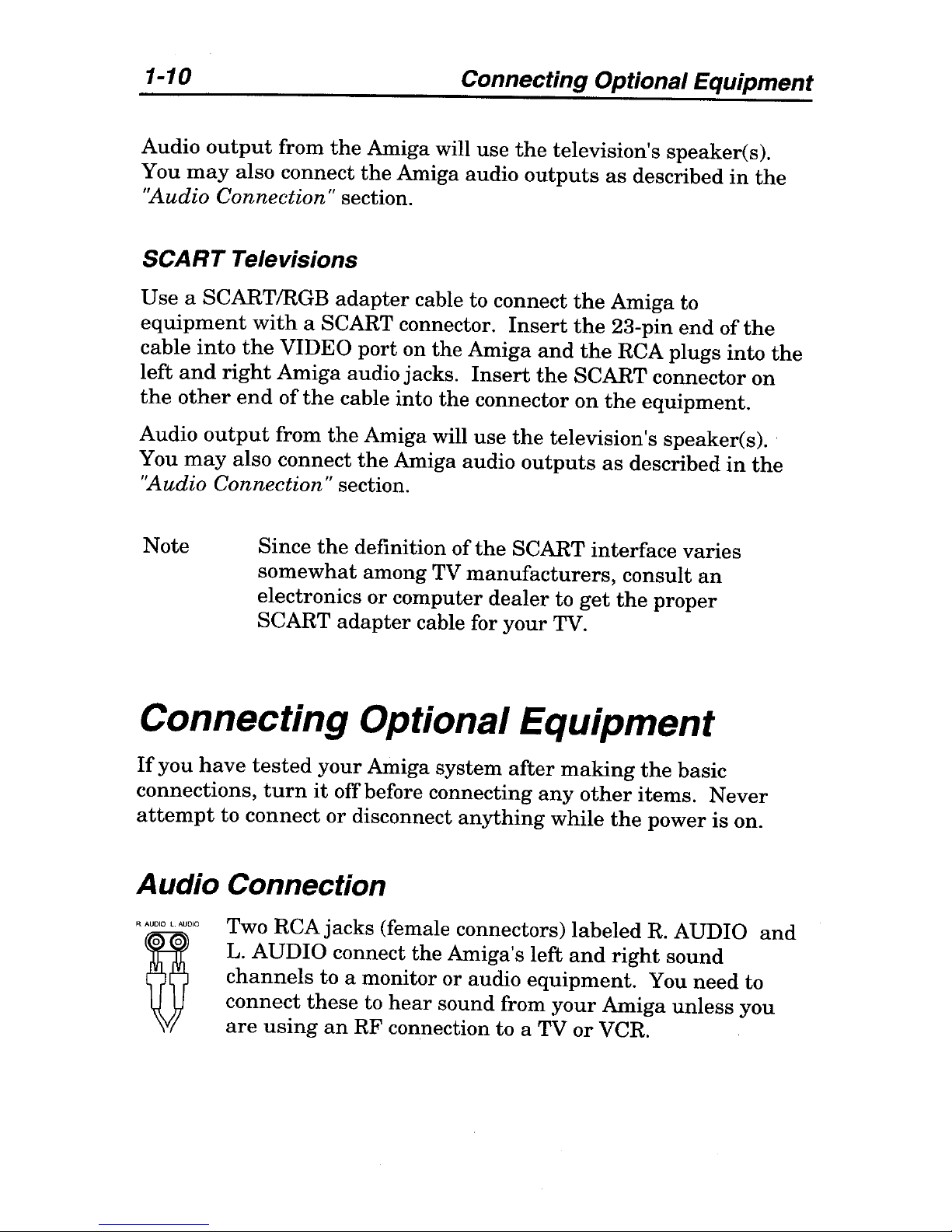
Audio Connection
Two
RCAjacks
(female connectors)
labeled
R. AUDIO
and
L. AUDIO connect
the
Amiga's left
and
right
sound
channels
to a monitor or audio
equipment.
You
need
to
connect
these
to
hear
sound from
your
Amiga
unless
you
are
using
an
RF
connection to a TV
or
VCR.
Connecting Optional Equipment
1-11
Audio Connection
to
a
Stereo Monitor
A
monitor
with
internal
speakers
allows
you
to
hear
the
Amiga's
sound
output
without
other
external
equipment.
An
Amiga
stereo
monitor
comes
with
a
stereo
cable, col or-coded for
the
left
and
right
channels.
Insert
the
connectors
at
one
end
of
the
cflble
into
the
Amiga's
left
and
right
audio
output
jacks.
Then
insert
the
cable's
other
connectors into
the
corresponding
audio
input
jacks
on
the
monitor.
Audio Connection to
a
Monaural Monitor
A
monitor
with
monaural
sound
capability
can
still
accept
both
Amiga
audio
channels.
Either
use
a
"Y"
adapter
cable
plugged
into
both
Amiga
audio jacks,
or
plug
a single audio cable
into
either
one
of
the
jacks.
Insert
the
other
end
of
the
cable
into
the
monitor's
audio
input
jack.
Both
audio
channels
will
be
routed
to
the
monitor
speaker.
Audio Connection
to
Other Equipment
If
your
monitor
does
not
have
speakers,
you
can
connect
the
Amiga's
audio
output
to
separate
powered
speakers,
a
stereo
system,
or
other
audio
equipment.
Use
input
connectors
labeled
Auxiliary,
Aux, Audio
In,
CD,
Tape,
VCR Audio, etc.
on
the
equipment.
You
need
a
stereo
audio cable
with
RCA connectors
at
one
end
and
the
appropriate
type
of connector for
your
equipment
at
the
other
end.
Audio cables
and
adapters
are
available
from
most
electronics
and
stereo
stores.
Insert
the
RCA connectors
into
the
Amiga's
audio
output
jacks
and
the
other
connectors
into
the
equipment's
corresponding
audio
input
jacks.
Consult
the
equipment's
user
manual
for
further
instructions
on
using
its
external
inputs.
 Loading...