

Page 1

AMIGA HARDWARE
REFERENCE MANUAL
© 1992 Commodore Business Machines
Amiga 1200 PAL
Page 2

AMIGA HARDWARE REFERENCE MANUAL
TABLE OF CONTENTS
Chapter 1 INTRODUCTION
Components of the Amiga ..................................2
THE MC68000 AND THE AMIGA CUSTOM CHIPS.................2
VCR AND DIRECT CAMERA INTERFACE........................5
PERIPHERALS............................................5
SYSTEM EXPANDABILITY AND ADAPTABILITY..................6
About the Examples........................................7
Some Caveats to Hardware Level Programmers ...............9
Chapter 2 COPROCESSOR HARDWARE ............................13
Introduction.............................................13
ABOUT THIS CHAPTER....................................14
What is a Copper Instruction? ...........................14
The MOVE Instruction ....................................15
The WAIT Instruction.....................................17
HORIZONTAL BEAM POSITION..............................18
VERTICAL BEAM POSITION ...............................18
THE COMPARISON ENABLE BITS............................19
Using the Copper Registers...............................20
LOCATION REGISTERS ...................................20
JUMP STROBE ADDRESS...................................21
CONTROL REGISTER......................................21
Putting Together a Copper Instruction List ..............22
COMPLETE SAMPLE COPPER LIST...........................24
LOOPS AND BRANCHES ...................................25
Starting and Stopping the Copper ........................25
STARTING THE COPPER AFTER RESET.......................25
STOPPING THE COPPER...................................26
Advanced Topics..........................................27
THE SKIP INSTRUCTION..................................27
COPPER LOOPS AND BRANCHES AND COMPARISON ENABLE.......28
USING THE COPPER IN INTERLACED MODE ..................30
USING THE COPPER WITH THE BLITTER.....................31
THE COPPER AND THE 68000..............................31
Summary of Copper Instructions ..........................32
Chapter 3 PLAYIELD HARDWARE................................33
Introduction.............................................33
ABOUT THIS CHAPTER....................................34
PLAYFIELD FEATURES ...................................34
Forming a Basic Playfield ...............................38
HEIGHT AND WIDTH OF THE PLAYFIELD.....................39
BIT-PLANES AND COLOR .................................39
SELECTING HORIZONTAL AND VERTICAL RESOLUTION .........43
ALLOCATING MEMORY FOR BIT-PLANES .....................46
CODING THE BIT-PLANES FOR CORRECT COLORING ...........49
DEFINING THE SIZE OF THE DISPLAY WINDOW ..............50
TELLING THE SYSTEM HOW TO FETCH AND DISPLAY DATA .....53
DISPLAYING AND REDISPLAYING THE PLAYFIELD ............56
ENABLING THE COLOR DISPLAY ...........................56
BASIC PLAYFIELD SUMMARY ..............................57
EXAMPLES OF FORMING BASIC PLAYFIELDS .................59
Forming a Dual-playfield Display ........................62
Page 3

Bit-Plane Assignment in Dual-playfield Mode .............62
COLOR REGISTERS IN DUAL-PLAYFIELD MODE ...............65
DUAL-PLAYFIELD PRIORITY AND CONTROL ..................66
ACTIVATING DUAL-PLAYFIELD MODE .......................67
DUAL PLAYFIELD SUMMARY ...............................67
Bit-planes and Display Windows of All Sizes .............68
WHEN THE BIG PICTURE IS LRGR THAN THE DISPLAY WINDOW .68
MAXIMUM DISPLAY WINDOW SIZE...........................74
Moving (Scrolling) Playfields ...........................75
VERTICAL SCROLLING....................................75
HORIZONTAL SCROLLING .................................77
SCROLLED PLAYFIELD SUMMARY ...........................80
Advanced Topics..........................................81
INTERACTIONS AMONG PLAYFIELDS AND OTHER OBJECTS ......81
HOLD-AND-MODIFY MODE .................................81
FORMING A DISPLAY WITH SEVERAL DIFFERENT PLAYFELD ....84
USING AN EXTERNAL VIDEO SOURCE .......................84
SUMMARY OF PLAYFIELD REGISTERS .......................84
Summary of Color Selection ..............................87
COLOR REGISTER CONTENTS ..............................87
SOME SAMPLE COLOR REGISTER CONTENTS ..................88
COLOR SELECTION IN LOW-RESOLUTION MODE ...............88
COLOR SELECTION IN HOLD-AND-MODIFY MODE ..............90
COLOR SELECTION IN HIGH-RESOLUTION MODE ..............90
Chapter 4 SPRITE HARDWARE .................................93
Introduction.............................................93
ABOUT THIS CHAPTER....................................94
Forming a Sprite ........................................94
SCREEN POSITION ......................................94
SIZE OF SPRITES ......................................97
SHAPE OF SPRITES .....................................97
SPRITE COLOR..........................................98
DESIGNING A SPRITE...................................101
BUILDING THE DATA STRUCTURE..........................101
Displaying a Sprite.....................................106
SELECTING A DMA CHANNEL AND SETTING THE POINTERS.....107
RESETTING THE ADDRESS POINTERS ......................107
SPRITE DISPLAY EXAMPLE...............................108
Moving a Sprite.........................................110
Creating Additional Sprites.............................111
SPRITE PRIORITY......................................112
Reusing Sprite DMA Channels ............................113
Overlapped Sprites......................................115
Attached Sprites .......................................117
Manual Mode ............................................120
Sprite Hardware Details ................................121
Summary of Sprite Registers.............................124
POINTERS.............................................124
CONTROL REGISTERS....................................124
DATA REGISTERS ......................................126
Summary of Sprite Color Registers.......................126
INTERACTIONS AMONG SPRITES AND OTHER OBJECTS ........128
Chapter 5 AUDIO HARDWARE..................................129
Introduction............................................129
INTRODUCING SOUND GENERATION.........................130
THE AMIGA SOUND HARDWARE.............................133
Forming and Playing a Sound ............................134
Page 4

DECIDING WHICH CHANNEL TO USE........................134
CREATING THE WAVEFORM DATA...........................134
TELLING THE SYSTEM ABOUT THE DATA ...................136
SELECTING THE VOLUME ................................136
SELECTING THE DATA OUTPUT RATE.......................137
PLAYING THE WAVEFORM ................................140
STOPPING THE AUDIO DMA...............................141
SUMMARY..............................................142
EXAMPLE..............................................142
Producing Complex Sounds................................143
JOINING TONES .......................................143
PLAYING MULTIPLE TONES AT THE SAME TIME..............145
MODULATING SOUND ....................................145
Producing High-quality Sound............................148
MAKING WAVEFORM TRANSITIONS .........................148
SAMPLING RATE .......................................148
EFFICIENCY...........................................149
NOISE REDUCTION......................................150
ALIASING DISTORTION .................................150
LOW-PASS FILTER .....................................152
Using Direct (Non-DMA) Audio Output ....................153
The Equal-tempered Musical Scale........................154
Decibel Values for Volume Ranges .......................159
The Audio State Machine.................................160
Chapter 6 BLITTER HARDWARE................................163
Introduction............................................163
Memory Layout ..........................................164
DMA Channels............................................164
Function Generator......................................168
DESIGNING THE LF CONTROL BYTE WITH MINTERMS..........169
DESIGNING THE LF CONTROL BYTE WITH VENN DIAGRAMS.....172
Shifts and Masks........................................173
Descending Mode ........................................176
Copying Arbitrary Regions...............................177
Area Fill Mode..........................................178
Blitter Done Flag.......................................180
MULTITASKING AND THE BLITTER ........................181
Interrupt Flag .........................................181
Zero Flag...............................................182
Pipeline Register.......................................182
Line Mode...............................................184
REGISTER SUMMARY FOR LINE MODE.......................186
Blitter Speed ..........................................188
Blitter Operations and System DMA ......................189
Blitter Block Diagram...................................193
Blitter Key Points......................................195
EXAMPLE: ClearMem....................................195
EXAMPLE: SimpleLine..................................197
EXAMPLE: RotateBits..................................199
Chapter 7 SYSTEM CONTROL HARDWARE ........................201
Introduction............................................201
Video Priorities .......................................202
FIXED SPRITE PRIORITES ..............................202
HOW SPRITES ARE GROUPED..............................203
UNDERSTANDING VIDEO PRIORITIES ......................203
SETTING THE PRIORITY CONTROL REGISTER................204
Collision Detection ....................................207
Page 5

HOW COLLISIONS ARE DETERMINED........................207
HOW TO INTERPRET THE COLLISION DATA .................208
HOW COLLISION DETECTION IS CONTROLLED ...............209
Beam Position Detection.................................210
USING THE BEAM POSITION COUNTER......................210
Interrupts .............................................211
NONMASKABLE INTERRUPT ...............................212
MASKABLE INTERRUPTS..................................212
USER INTERFACE TO THE INTERRUPT SYSTEM ..............212
INTERRUPT CONTROL REGISTERS .........................212
SETTING AND CLEARING BITS............................213
DMA Control ............................................217
Processor Access to Chip Memory.........................217
Reset and Early Startup Operation.......................219
Chapter 8 INTERFACE HARDWARE..............................221
Introduction............................................221
Controller Port Interface...............................222
REGISTERS USED WITH THE CONTROLLER PORT..............223
Floppy Disk Controller .....,.............................235
REGISTERS USED BY THE DISK SUBSYSTEM ................236
DISK INTERRUPTS .....................................244
The Keyboard............................................245
HOW THE KEYBOARD DATA IS RECEIVED....................245
TYPE OF DATA RECEIVED................................245
LIMITATIONS OF THE KEYBOARD .........................247
Parallel Input/Output Interface.........................250
Serial Interface .......................................250
INTRODUCTION TO SERIAL CIRCUITRY ....................250
SETTING THE BAUD RATE................................250
SETTING THE RECEIVE MODE ............................251
CONTENTS OF THE RECEIVE DATA REGISTER................251
HOW OUTPUT DATA IS TRANSMITTED.......................253
SPECIFYING THE REGISTER CONTENTS ....................254
Display Output Connections .............................255
Appendix A Register Summary-Alphabetical Order............257
Appendix B Register Summary-Address Order.................281
Appendix C Custom Chip Pin Allocation List................289
Appendix D System Memory Map..............................293
Appendix E Interfaces ....................................295
Appendix F Complex Interface Adapters.....................317
8520 Complex Interface Adaptor (CIA) Chips..............317
Chip Register Map.......................................319
Register Functional Description.........................320
I/O PORTS (PRA, PRB, DDRA, DDRB).....................320
HANDSHAKING..........................................320
INTERVAL TIMERS (TIMER A, TIMER B)...................320
INPUT MODES..........................................322
BIT NAMES on READ-Register...........................322
BIT NAMES on WRITE-Register .........................322
Time of Day Clock.......................................323
BIT NAMES for WRITE TIME/ALARM or READ TIME..........323
Serial Shift Register (SDR).............................324
Page 6

INPUT MODE ..........................................324
OUTPUT MODE .........................................324
BIDIRECTIONAL FEATURE ...............................325
Interrupt Control Register (ICR) .......................325
READ INTERRUPT CONTROL REGISTER .....................326
WRITE INTERRUPT CONTROL MASK ........................326
Control Registers ......................................327
CONTROL REGISTER A ..................................327
BIT MAP OF REGISTER CRA .............................328
BIT MAP OF REGISTER CRB .............................329
Port Signal Assignments.................................329
Hardware Connection Details.............................332
INTERFACE SIGNALS ...................................332
Appendix G AUTOCONFIG ....................................335
Debugging AUTOCONFIG Boards.............................336
Address Specification Table.............................337
Appendix H Keyboard.......................................343
Keyboard Communications.................................344
Keycodes................................................345
"CAPS LOCK" Key.........................................345
"Out-of-Sync" Condition.................................346
Power-Up Sequence ......................................346
Reset Warning...........................................348
Hard Reset..............................................348
Special Codes...........................................349
Matrix Table............................................350
Appendix I External Disk Connector Interface Spec. .......353
General.................................................353
Summary Table...........................................354
Signals When Driving a Disk.............................355
Device I.D..............................................357
Appendix J Hardware Example Include File..................359
Glossary .................................................365
Index ....................................................373
Page 7

LIST OF FIGURES
Figure 1-1 Block Diagram for the Amiga Computer Family............11
Figure 2-1 Interlaced Bit-Plane in RAM............................30
Figure 3-1 How the Video Display Picture Is Produced..............34
Figure 3-2 What Is a Pixel?.......................................35
Figure 3-3 How Bit-planes Select a Color..........................37
Figure 3-4 Significance of Bit-Plane Data in Selecting Colors.....38
Figure 3-5 Interlacing............................................44
Figure 3-6 Effect of Interlaced Mode on Edges of Objects..........44
Figure 3-7 Memory Organization for a Basic Bit-Plane..............48
Figure 3-8 Combining Bit-planes...................................50
Figure 3-9 Positioning the On-screen Display......................51
Figure 3-10 Data Fetched for the First Line When Modulo=0 ........54
Figure 3-11 Data Fetched for the Second Line When Modulo=0........55
Figure 3-12 A Dual-playfield Display..............................63
Figure 3-13 How Bit-Planes Are Assigned to Dual Playfields........64
Figure 3-14 Memory Picture Larger than the Display................69
Figure 3-15 Data Fetch for the First Line When Modulo=40..........69
Figure 3-16 Data Fetch for the Second Line When Modulo=40.........70
Figure 3-17 Data Layout for First Line-Right Half of Big Picture..70
Figure 3-18 Data Layout for Second Line-Right Half of Big Picture.70
Figure 3-19 Display Window Horizontal Starting Position ..........72
Figure 3-20 Display Window Vertical Starting Position ............72
Figure 3-21 Display Window Horizontal Stopping Position .........73
Figure 3-22 Display Window Vertical Stopping Position ............74
Figure 3-23 Vertical Scrolling....................................76
Figure 3-24 Horizontal Scrolling .................................78
Figure 3-25 Memory Picture Larger than the Display Window ........79
Figure 3-26 Data for Line 1 - Horizontal Scrolling ...............79
Figure 3-27 Data for Line 2 - Horizontal Scrolling ...............79
Figure 4-1 Defining Sprite On-screen Position.....................95
Figure 4-2 Position of Sprites ...................................96
Figure 4-3 Shape of Spaceship.....................................97
Figure 4-4 Sprite with Spaceship Shape Defined ...................98
Figure 4-5 Sprite Color Definition ...............................99
Figure 4-6 Color Register Assignments ...........................100
Figure 4-7 Data Structure Layout ................................103
Figure 4-8 Sprite Priority ......................................112
Figure 4-9 Typical Example of Sprite Reuse ......................113
Figure 4-10 Typical Data Structure for Sprite Re-use ............114
Figure 4-11 Overlapping Sprites (Not Attached) ..................116
Figure 4-12 Placing Sprites Next to Each Other ..................117
Figure 4-13 Sprite Control Circuitry ............................122
Figure 5-1 Sine Waveform ........................................131
Figure 5-2 Digitized Amplitude Values ...........................133
Figure 5-3 Example Sine Wave ....................................139
Figure 5-4 Waveform with Multiple Cycles ........................149
Figure 5-5 Frequency Domain Plot of Low-Pass Filter .............151
Figure 5-6 Noise-free Output (No Aliasing Distortion) ...........151
Figure 5-7 Some Aliasing Distortion .............................152
Figure 5-8 Audio State Diagram ..................................162
Figure 6-1 How Images are Stored in Memory ......................165
Figure 6-2 BLTxP and BLTxMOD calculations .......................167
Figure 6-3 Blitter Minterm Venn Diagram .........................172
Figure 6-4 Extracting a Range of Columns ........................175
Figure 6-5 Use of the FCI Bit - Bit Is a 0 ......................179
Figure 6-6 Use of the FCI Bit - Bit Is a 1 ......................179
Figure 6-7 Single-Point Vertex Example ..........................180
Figure 6-8 Octants for Line Drawing .............................184
Page 8

Figure 6-9 DMA Time Slot Allocation .............................190
Figure 6-10 Norma 68000 Cycle ...................................191
Figure 6-11 Time Slots Used by a Six Bit Plane Display ..........192
Figure 6-12 Time Slots Used by a High Resolution Display ........192
Figure 6-13 Blitter Block Diagram ...............................194
Figure 7-1 Inter-Sprite Fixed Priorities ........................202
Figure 7-2 Analogy for Video Priority ...........................203
Figure 7-3 Sprite playfield Priority ............................206
Figure 7-4 Interrupt Priorities .................................216
Figure 8-1 Controller Plug and Computer Connector ...............222
Figure 8-2 Mouse Quadrature .....................................224
Figure 8-3 Joystick to Counter Connections ......................227
Figure 8-4 Typical Paddle Wiring Diagram ........................229
Figure 8-5 Effects of Resistance on Charging Rate ...............230
Figure 8-6 Potentiometer Charging Circuit .......................231
Figure 8-7 Chinon Timing Diagram ................................236
Figure 8-8 Chinon Timing Diagram (cont.) ........................237
Figure 8-9 The A1000 Keyboard, Showing Keycodes in Hex ..........249
Figure 8-10 The A500/2000 Keyboard, Keycodes in Hex .............249
Figure 8-11 Starting Appearance of SERDAT and Shift Reg .........254
Figure 8-12 Ending Appearance of Shift Register..................254
Figure G-1 How to read the Address Specification Table ..........338
Page 9

LIST OF TABLES
Table 2-1 Interrupting the 68000..................................31
Table 2-2 Copper Instruction Summary .............................32
Table 3-1 Colors in a Single Playfield............................39
Table 3-2 Portion of the Color Table .............................40
Table 3-3 Contents of the Color Registers ........................41
Table 3-4 Sample Color Register Contents .........................41
Table 3-5 Setting the Number of Bit-Planes........................42
Table 3-6 Lines in a Normal Playfield.............................43
Table 3-7 Playfield Memory Requirements, NTSC.....................46
Table 3-8 Playfield Memory Requirements, PAL .....................47
Table 3-9 DIWSTRT AND DIWSTOP Summary.............................53
Table 3-10 Playfield 1 Color Registers-Low-resolution Mode........65
Table 3-11 Playfield 2 Color Registers-Low-resolution Mode........65
Table 3-12 Playfields 1 & 2 Color Registers High-res Mode.........66
Table 3-13 Maximum Allowable Vertical Screen Video................74
Table 3-14 Maximum Allowable Horizontal Screen Video .............75
Table 3-15 Color Register Contents................................87
Table 3-16 Some Register Values and Resulting Colors..............88
Table 3-17 Low-resolution Color Selection ........................89
Table 3-18 Color Selection in Hold-and-modify Mode................90
Table 3-19 High-resolution Color Selection........................91
Table 4-1 Sprite Data Structure..................................102
Table 4-2 Sprite Color Registers ................................105
Table 4-3 Color Registers for Sprite Pairs.......................112
Table 4-4 Data Words for First Line of Spaceship Sprite..........118
Table 4-5 Color Registers in Attached Sprites ...................119
Table 4-6 Color Registers for Single Sprites.....................127
Table 4-7 Color Registers for Attached Sprites...................128
Table 5-1 Sample Audio Data Set for Channel 0 ...................135
Table 5-2 Volume Values .........................................137
Table 5-3 DMA and Audio Channel Enable Bits......................141
Table 5-4 Data Interpretation in Attach Mode.....................146
Table 5-5 Channel Attachment for Modulation......................147
Table 5-6 Sampling Rate and Frequency Relationship...............153
Table 5-7 Equal-tempered Octave for a 16 Byte Sample.............154
Table 5-8 Five Octave Even-tempered Scale........................156
Table 5-9 Decibel Values and Volume Ranges.......................159
Table 6-1 Table of Common Minterm Values.........................171
Table 6-2 Typical Blitter Cycle Sequence.........................183
Table 6-3 BLTCON1 Code Bits for Octant Line Drawing..............185
Table 7-1 Bits in BPLCON2........................................204
Table 7-2 Prirty of Plyflds Based on Values of Bits PF1P2-PF1P0..205
Table 7-3 CLXDAT Bits............................................208
Table 7-4 CLXCON Bits ...........................................209
Table 7-5 Contents of the Beam Position Counter..................211
Table 7-6 Contents of DMA Register...............................218
Table 8-1 Typical Controller Connections ........................223
Table 8-2 Determining the Direction of the Mouse.................226
Table 8-3 Interpreting Data from JOY0DAT and JOY1DAT.............228
Table 8-4 POTGO ($DFF034) and POTINP ($DFF016) Registers.........234
Table 8-5 Disk Subsystem ........................................238
Table 8-6 DSKLEN Register ($DFF024)..............................240
Table 8-7 DSKBYTR Register.......................................242
Table 8-8 ADKCON and ADKCONR Register............................243
Table 8-9 SERDATR / ADKCON Registers.............................252
Table G-1 Address Specification Table............................338
Page 10

CHAPTER 1
INTRODUCTION
The Amiga family of computers consists of several models, each of which has been
designed on the same premise to provide the user with a low cost computer that features
high cost performance. The Amiga does this through the use of custom silicon hardware
that yields advanced graphics and sound features.
There are three distinct models that make up the Amiga computer family: the A500,
A1000, and A2000. Though the models differ in price and features, they have a common
hardware nucleus that makes them software compatible with one another. This chapter
describes the Amiga's hardware components and gives a brief overview of its graphics and
sound features.
- Introduction 1 -
Page 11

COMPONENTS OF THE AMIGA
These are the hardware components of the Amiga:
o Motorola MC68000 16/32 bit main processor. The Amiga also supports the 68010,
68020, and 68030 processors as an option.
o 512K bytes of internal RAM, expandable to 1 MB on the A500 and A2000.
o 256K bytes of ROM containing a real time, multitasking operating system with sound,
graphics, and animation support routines.
o Built-in 3.5 inch double sided disk drive.
o Expansion disk port for connecting up to three additional disk drives, which may be
either 3.5 inch or 5.25 inch, double sided.
o Fully programmable RS-232-C serial port.
o Fully programmable parallel port.
o Two button opto-mechanical mouse.
o Two reconfigurable controller ports (for mice, joysticks, light pens, paddles, or custom
controllers).
o A professional keyboard with numeric keypad, 10 function keys, and cursor keys. A
variety of international keyboards are also supported.
o Ports for simultaneous composite video, and analog or digital RGB output.
o Ports for left and right stereo audio from four special purpose audio channels.
o Expansion options that allow you to add RAM, additional disk drives (floppy or hard),
peripherals, or co-processors.
THE MC6X000 AND THE AMIGA CUSTOM CHIPS
The Motorola 68000 is a 16/32 bit microprocessor. The system clock speed for NTSC
Amiga’s is 7.15909 megahertz (PAL 7.09379 MHz). These speeds may vary when using an
external system clock, such as from a genlock. The 68000 has an address space of 16
megabytes. In the Amiga, the 68000 can address over 8 megabytes of continuous random
access memory (RAM).
- 2 Introduction -
Page 12

In addition to the 68000, the Amiga contains special purpose hardware known as the
"custom chips" that greatly enhance system performance. The term "custom chips" refers
to the 3 integrated circuits which were designed specifically for the Amiga computer.
These three custom chips (called Agnus, Paula, and Denise) each contain the logic to
handle a specific set of tasks, such as video, sound, direct memory access (DMA),
or graphics.
Among other functions, the custom chips provide the following:
Bitplane generated, high resolution graphics capable of supporting both PAL and
NTSC video standards.
o On NTSC systems the Amiga typically produces a 320 by 200 non-interlaced
or 320 by 400 interlaced display in 32 colors and a 640 by 200 noninterlaced or 640 by 400 interlaced display in 16 colors.
o On PAL systems, the Amiga typically produces a 320 by 256 non-interlaced
or 320 by 512 interlaced display in 32 colors, and a 640 by 256 noninterlaced or 640 by 512 interlaced display in 16 colors.
Additional video modes allow for the display of up to 4,096 colors on screen
simultaneously (hold-and-modify) or provide for larger, higher resolution displays
(overscan).
A custom display co-processor that allows changes to most of the special purpose
registers in synchronization with the position of the video beam. This allows such
special effects as mid-screen changes to the color palette, splitting the screen into
multiple horizontal slices each having different video resolutions and color depths,
beam synchronized interrupt generation for the 68000 and more. The co-processor
can trigger many times per screen, in the middle of lines, and at the beginning or
during the blanking interval. The co-processor itself can directly affect most of the
registers in the other custom chips, freeing the 68000 for general computing tasks.
32 system color registers, each of which contains a twelve bit number as four bits
of RED, four bits of GREEN, and four bits of BLUE intensity information. This allows
a system color palette of 4,096 different choices of color for each register.
Eight reusable 16 bit wide sprites with up to 15 color choices per sprite pixel (when
sprites arc paired). A sprite is an easily movable graphics object whose display is
entirely independent of the background (called a playfield); sprites can be
displayed over or under this background. A sprite is 16 low resolution pixels wide
and an arbitrary number of lines tall. After producing the last line of a sprite on the
screen, a sprite DMA channel may be used to produce yet another sprite image
elsewhere on screen (with at least one horizontal line between each reuse of a
sprite processor). Thus, many small sprites can be produced by simply reusing the
sprite processors appropriately.
Dynamically controllable inter-object priority, with collision detection. This means
that the system can dynamically control the video priority between the sprite
objects and the bitplane backgrounds (playfields). You can control which object or
objects appear over or under the background at any time.
Page 13

Additionally, you can use system hardware to detect collisions between objects and have
your program react to such collisions.
o Custom bit blitter used for high speed data movement, adaptable to bitplane animation.
The blitter has been designed to efficiently retrieve data from up to three sources,
combine the data in one of 256 different possible ways, and optionally store the combined
data in a destination area. This is one of the situations where the 68000 gives up memory
cycles to a DMA channel that can do the job more efficiently (see below). The bit blitter, in
a special mode, draws patterned lines into rectangularly organized memory regions at a
speed of about 1 million dots per second; and it can efficiently handle area fill.
o Audio consisting of four digital channels with independently programmable volume and
sampling rate. The audio channels retrieve their control and data via direct memory
access. Once started, each channel can automatically play a specified waveform without
further processor interaction. Two channels are directed into each of the two stereo audio
outputs. The audio channels may be linked together to provide amplitude or frequency
modulation or both forms of modulation simultaneously.
o DMA controlled floppy disk read and write on a full track basis. This means that the
built-in disk can read over 5600 bytes of data in a single disk revolution (11 sectors of
512 bytes each).
The internal memory shared by the custom chips and the 68000 CPU is also called "chip
memory". The original custom chips in the Amiga were designed to be able to physically
access up to 512K bytes of shared memory. The new version of the Agnus custom chip
was created which allows the graphics and audio hardware to access up to a full megabyte
of memory.
The Amiga 500 and 2000 models were designed to be able to accept the new Agnus
custom chip, called "Fat Agnus", due to its square shape. Hence, the A500 and A2000
have allocated a chip memory space of 1 MB. This entire 1 MB space is subject to the
arbitration logic that controls the CPU and custom chip accesses. On the A1000, only the
first 512K bytes of memory space is shared, chip memory.
These custom chips and the 68000 share memory on a fully interleaved basis. Since the
68000 only needs to access the memory bus during each alternate clock cycle in order to
run full speed, the rest of the time the memory bus is free for other activities. The custom
chips use the memory bus during these free cycles, effectively allowing the 68000 to run
at full rated speed most of the time. We say "most of the time" because there are some
occasions when the special purpose hardware steals memory cycles from the 68000, but
with good reason. Specifically, the coprocessor and the data moving DMA channel called
the blitter can each steal time from the 68000 for jobs they can do better than the 68000.
Thus, the system DMA channels are designed with maximum performance in mind. The
job to be done is performed by the most efficient hardware element available. Even when
such cycle stealing occurs, it only blocks the 68000's access to the internal, shared
memory. When using ROM or external memory, the 68000 always runs at full speed.
- 4 Introduction -
Page 14

Another primary feature of the Amiga hardware is the ability to dynamically control which
part of the chip memory is used for the background display. audio, and sprites. The Amiga
is not limited to a small, specific area of RAM for a frame buffer. Instead, the system
allows display bitplanes, sprite processor control lists, coprocessor instruction lists, or
audio channel control lists to be located anywhere within chip memory.
This same region of memory can be accessed by the bit blitter. This means, for example,
that the user can store partial images at scattered areas of chip memory and use these
images for animation effects by rapidly replacing on screen material while saving and
restoring background images. In fact, the Amiga includes firmware support for display
definition and control as well as support for animated objects embedded within playfields.
VCR AND DIRECT CAMERA INTERFACE
In addition to the connectors for monochrome composite, and analog or digital RGB
monitors, the Amiga can be expanded to include a VCR or camera interface. This system
is capable of synchronizing with an external video source and replacing the system
background color with the external image. This allows development of fully integrated
video images with computer generated graphics. Laser disk input is accepted in the same
manner.
PERIPHERALS
Floppy disk storage is provided by a built in, 3.5 inch floppy disk drive. Disks are 80 track,
double sided, and formatted as 11 sectors per track, 512 bytes per sector (over 900,000
bytes per disk). The disk controller can read and write 320/360K IBM PC (MS-DOS)
formatted 3.5 or 5.25 inch disks, and 640/720K IBM PC (MS-DOS) formatted 3.5 inch
disks. External 3.5 inch or 5.25 inch disk drives can be added to the system through the
expansion connector. Circuitry for some of the peripherals resides on Paula. Other chips
handle various signals not specifically assigned to any of the custom chips, including
modem controls, disk status sensing, disk motor and stepping controls, ROM enable,
parallel input/output interface, and keyboard interface.
The Amiga includes a standard RS-232-C serial port for external serial input/output
devices.
A keyboard with numeric keypad, cursor controls and 10 function keys is included in the
base system. For maximum flexibility, both key-down and key-up signals are sent. The
Amiga also supports a variety of international keyboards. Many other types of controllers
can be attached through the two controller ports on the base unit. You can use a mouse,
joystick, keypad, track-ball, light pen, or steering wheel controller in either of the
controller ports.
- Introduction 5 -
Page 15

SYSTEM EXPANDABILITY AND ADAPTABILITY
New peripheral devices may be easily added to all Amiga models. These devices are
automatically recognized and used by system software through a well defined, well
documented linking procedure called AUTOCONFIG.
On the A500 and A1000 models, peripheral devices can be added to the Amiga's 86 pin
expansion connector, including additional external RAM. Extra disk units may be added
from a connector at the rear of the unit.
The A2000 model provides the user with the same features as the A500 or A1000, but
with the added convenience of simple and extensive expandability. The 86 pin, external
connector of the A1000 and A500 is not externally accessible on the A2000. Instead, the
A2000 contains 7 internal slots that allow many types of expansion boards to be quickly
and easily added inside the machine. These expansion boards may contain coprocessors,
RAM expansion, hard disk controllers, video or I/O ports. There is also room to mount
both floppy and hard disks internally. The A2000 also supports the special Bridgeboard
coprocessor card. This provides a complete IBM PC on a card and allows the Amiga to run
MS-DOS compatible software, while simultaneously running native Amiga software.
- 6 Introduction -
Page 16

ABOUT THE EXAMPLES
The examples in this book all demonstrate direct manipulation of the Amiga hardware.
However, as a general rule, it is not permissible to directly access the hardware in the
Amiga unless your software either has full control of the system, or has arbitrated via the
OS for exclusive access to the particular parts of the hardware you wish to control.
Almost all of the hardware discussed in this manual, most notably the Blitter, Copper,
playfield, sprite, CIA, trackdisk, and system control hardware, are in either exclusive or
arbitrated use by portions of the Amiga OS in any running Amiga system. Additional
hardware, such as the audio, parallel, and serial hardware, may be in use by applications
which have allocated their use through the system software.
Before attempting to directly manipulate any part of the hardware in the Amiga's
multitasking environment, your application must first be granted exclusive access to that
hardware by the operating system library, device, or resource which arbitrates its
ownership. The operating system functions for requesting and receiving control of parts of
the Amiga hardware are varied and are not within the scope of this manual. Generally
such functions, when available, will be found in the library, device, or resource which
manages that portion of the Amiga hardware in the multitasking environment. The
following list will help you to find the appropriate operating system functions or
mechanisms which may exist for arbitrated access to the hardware discussed in this
manual.
Copper, Playfield, Sprite, Blitter - graphics.library
Audio - audio.device
Trackdisk - trackdisk.device, disk.resource
Serial - serial.device, misc.resource
Parallel - parallel.device, cia.resource, misc.resource
Gameport - input.device, gameport.device, potgo.resource
Keyboard - input.device, keyboard.device
System Control - graphics.library, exec.library (interrupts)
Most of the examples in this book use the hw_examples.i file (see Appendix J) to define
the chip register names. hw_examples.i uses the system include file hardware/custom.i to
define the chip structures and relative addresses. The values defined in hardware/custom.i
and how examples.i are offsets from the base chip register address space. In general, this
base value is defined as _custom and is resolved during linking from amiga.lib. (_ciaa and
_ciab are also resolved in this way.)
Normally, the base address is loaded into an address register and the offsets given by
hardware/custom.i and hw_examples.i are then used to address the correct register.
- Introduction 7 -
Page 17

NOTE
The offset values of the registers are the addresses that the Copper must use to talk to
the registers. For example, in assembler:
INCLUDE "exec/types.i"
INCLUDE "hardware/custom.i"
XREF custom ; External reference
Start: lea _custom,a0 ; Use a0 as base register
move.w #$7FFF,intena(a0) ; Disable all interrupts
In C, you would use the structure definitions in hardware/custom.h For
example:
#include "exec/types.h"
#include "hardware/custom.h"
extern struct Custom custom;
/* You may need to define the above external as
** extern struct Custom far custom;
** Check you compiler manual.
*/
main()
{
custom.intena = 0x7FFF; /* Disable all interrupts */
}
The Amiga hardware include files are generally supplied with your compiler or assembler.
Listings of the hardware include files may also be found in the Addison-Wesley Amiga ROM
Kernel Manual "Includes and Autodocs". Generally, the include file label names are very
similar to the equivalent hardware register list names with the following typical
differences.
o Address registers which have low word and high word components are generally listed
as two word sized registers in the hardware register list, with each register name
containing either a suffix or embedded "L" or "H" for low and high. The include file label
for the same register will generally treat the whole register as a longword (32 bit)
register,
and therefore will not contain the "L" or "H" distinction.
o Related sequential registers which are given individual names with number suffixes in
the hardware register list, are generally referenced from a single base register definition
in the include files. For example, the color registers in the hardware list (COLOR00,
COLOR01, etc.) would be referenced from the "color" label defined in "hardware/custom.i"
(color+0, color+2, etc.).
o Examples of how to define the correct register offset can be found in the hw_examples.i
file listed in Appendix J.
- 8 Introduction -
Page 18

SOME CAVEATS TO HARDWARE LEVEL PROGRAMMERS
The Amiga is available in a variety of models and configurations, and is further diversified
by a wealth of add-on expansion peripherals and processor replacements. In addition,
even standard Amiga hardware such as the keyboard and floppy disks, are supplied by a
number of different manufacturers and may vary subtly in both their timing and in their
ability to perform outside of their specified capabilities.
The Amiga operating system is designed to operate the Amiga hardware within spec,
adapt to different hardware and RAM configurations, and generally provide upward
compatibility with any future hardware upgrades or "add ons" envisioned by the
designers. For maximum upward compatibility, it is strongly suggested that programmers
deal with the hardware through the commands and functions provided by the Amiga
operating system.
If you find it necessary to program the hardware directly, then it is your responsibility to
write code which will work properly on various models and configurations. Be sure to
properly request and gain control of the hardware you are manipulating, and be especially
careful in the following areas:
Do not jump into ROM. Beware of any example code that calls routines in the $F80000 to
$FFFFFF range. These are ROM addresses and the ROM routines WILL move with every OS
revision. The only supported interface to system ROM code is through the provided library,
device, and resource calls.
Do not modify or depend on the format of any private system structures. This includes the
poking of copper lists, memory lists, and library bases.
Do not depend on any address containing any particular system structure or type of
memory. The system modules dynamically allocate their memory space when they are
initialized. The addresses of system structures and buffers differ with every OS, every
model, and every configuration, as does the amount of free memory and system stack
usage. Remember that all data for direct custom chip access must be in CHIP RAM. This
includes bit images (bitplanes, sprites, etc), sound samples, trackdisk buffers, and copper
lists.
Do not write spurious data to, or interpret undefined data from currently unused bits or
addresses in the custom chip space. All undefined bits must be set to zero for writes, and
ignored on reads.
Do not write data past the current end of custom chip space. Custom chips may be
extended or enhanced to provide additional registers, or to use currently undefined bits in
existing registers.
All custom chip registers are read only OR write only. Do not read write only registers, and
do not write to read only registers.
- Introduction 9 -
Page 19

Do not read, write, or use any currently undefined address ranges. The current and future
usage of such areas is reserved by Commodore and is definitely subject to change.
If you are using the system libraries, devices, and resources, you must follow the defined
interface. Assembler programmers (and compiler writers) must enter functions through
the library base jump Tables, with arguments passed as longs and library base address in
A6. Results returned in D0 must be tested, and the contents of D0-D1/A0-A1 must be
assumed gone after a system call.
NOTE
The assembler TAS instruction should not be used in any Amiga program. The TAS
instruction assumes an indivisible read-modify-write but this can be defeated by system
DMA. Instead use BSET and BCLR. These instructions perform a test and set operation
which cannot be interrupted.
TAS is only needed for a multiple CPU system. On a single CPU system, the BSET and
BCLR instructions are identical to TAS, as the 68000 does not interrupt instructions in the
middle. BSET and BCLR first test, then set bits.
Do not use assembler instructions which are privileged on any 68000 family processor,
most notably MOVE SR,<ea> which is privileged on the 68010/20/30. Use the Exec
function GetCC() instead of MOVE SR, or use the appropriate non-privileged instruction as
shown below:
CPU User Mode Super Mode
68000 MOVE SR,<ea> MOVE SR,<ea>
68010/20/30 MOVE CCR,<ea> MOVE SR,<ea>
All addresses must be 32 bits. Do not use the upper 8 bits for other data, and do not use
signed variables or signed math for addresses. Do not execute code on your stack or use
self-modifying code since such code can be defeated by the caching capabilities of some
68xxx processors. And never use processor or clock speed dependent software loops for
timing delays. See Appendix F for information on using an 8520 timer for delays.
NOTE
When strobing any register which responds to either a read or a write, (for example
copjmp2) be sure to use a MOVE.W #$00, not CLR.W. The CLR instruction causes a read
and a clear (two accesses) on a 68000, but only a single access on 68020 and above. This
will give different results on different processors.
If you are programming at the hardware level, you must follow hardware interfacing
specifications. All hardware is NOT the same. Do not assume that low level hacks for
speed or copy protection will work on all drives, or all keyboards, or all systems, or future
systems. Test your software on many different systems, with different processors, OS,
hardware, and RAM configurations.
- 10 Introduction -
Page 20
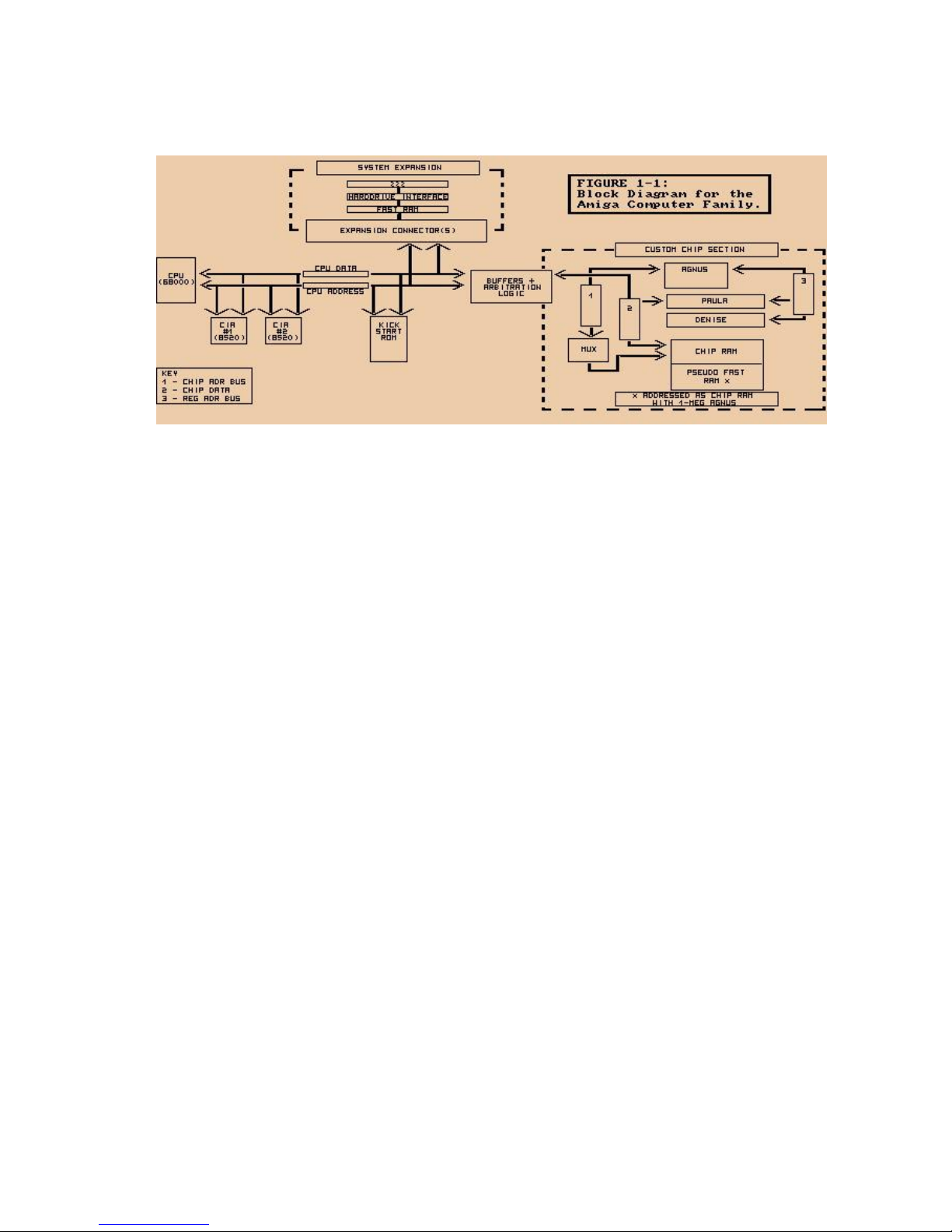
Figure 1-1: Block Diagram for the Amiga Computer Family.
- Introduction 11 -
Page 21

- 12 Introduction -
Page 22

Chapter 2
COPROCESSOR HARDWARE
INTRODUCTION
The Copper is a general purpose coprocessor that resides in one of the Amiga's custom
chips. It retrieves is instructions via direct memory access (DMA). The Copper can control
nearly the entire graphics system, freeing the 68000 to execute program logic; it can also
directly affect the contents of most of the chip control registers. It is a very powerful tool
for directing mid-screen modifications in graphics displays and for directing the register
changes that must occur during the vertical blanking periods. Among other things, it can
control register updates, reposition sprites, change the color palette, update the audio
channels, and control the blitter.
- Coprocessor Hardware 13 -
Page 23

One of the features of the Copper is its ability to WAIT for a specific video beam position,
then MOVE data into a system register. During the WAIT period, the Copper examines the
contents of the video beam position counter directly. This means that while the Copper is
waiting for the beam to reach a specific position, it does not use the memory bus at all.
Therefore, the bus is freed for use by the other DMA channels or by the 68000.
When the WAIT condition has been satisfied, the Copper steals memory cycles from either
the blitter or the 68000 to move the specified data into the selected special-purpose
register.
The Copper is a two-cycle processor that requests the bus only during odd-numbered
memory cycles. This prevents collision with audio, disk, refresh, sprites, and most lowresolution display DMA access, all of which use only the even-numbered memory cycles.
The Copper, therefore, needs priority over only the 68000 and the blitter (the DMA
channel that handles animation, line drawing, and polygon filling).
As with all the other DMA channels in the Amiga system, the Copper can retrieve its
instructions only from the chip RAM area of system memory.
ABOUT THIS CHAPTER
In this chapter, you will learn how to use the special Copper instruction set to organize
mid-screen register value modifications and pointer register set-up during the vertical
blanking interval. The chapter shows how to organize Copper instructions into Copper
lists, how to use Copper lists in interlaced mode, and how to use the Copper with the
blitter. The Copper is discussed in this chapter in a general fashion. The chapters that deal
with playfields, sprites, audio, and the blitter contain more specific suggestions for using
the Copper.
WHAT IS A COPPER INSTRUCTION?
As a coprocessor, the Copper adds its own instruction set to the instructions already
provided by the 68000. The Copper has only three instructions, but you can do a lot with
them:
o WAIT for a specific screen position specified as x and y co-ordinates.
o MOVE n immediate data value into one of the special-purpose registers.
o SKIP the next instruction if the video beam has already reached a specified screen
position.
- 14 Coprocessor Hardware -
Page 24

All Copper instructions consist of two 16-bit words in sequential memory locations. Each
time the Copper fetches an instruction, it fetches both words. The MOVE and SKIP
instructions require two memory cycles and two instruction words. Because only the odd
memory cycles are requested by the Copper, four memory cycle times are required per
instruction. The WAIT instruction requires three memory cycles and six memory cycle
times; it takes one extra memory cycle to wake up.
Although the Copper can directly affect only machine registers, it can affect the memory
by setting up a blitter operation. More information about how to use the Copper in
controlling the blitter can be found in the sections called "Control Register" and "Using the
Copper with the Blitter."
The WAIT and MOVE instructions are described below. The SKIP instruction is described in
the "Advanced Topics" section.
THE MOVE INSTRUCTION
The MOVE instruction transfers data from RAM to a register destination. The transferred
data is contained in the second word of the MOVE instruction; the first word contains the
address of the destination register. This procedure is shown in detail in the section called
"Summary of Copper Instructions."
FIRST INSTRUCTION WORD (IR1)
Bit 0 Always set to 0.
Bits 8 - 1 Register destination address (DA8-1).
Bits 15 - 9 Not used, but should be set to 0.
SECOND INSTRUCTION WORD (IR2)
Bits 15 - 0 16 bits of data to be transferred (moved) to the register
destination.
- Coprocessor Hardware 15 -
Page 25

The Copper can store data into the following registers:
o Any register whose address is $20 or above.
o Any register whose address is between $10 and $20 if the Copper danger bit is a 1. The
Copper danger bit is in the Copper's control register, COPCON, which is described in the
"Control Register" section.
o The Copper cannot write into any register whose address is lower than $10.
Appendix B contains all of the machine register addresses.
The following example MOVE instructions point bit-plane pointer 1 at $21000 and bitplane pointer 2 at S25000.2
DC.W $00E0,$0002 ;Move $0002 to register $0E0 (BPL1PTH)
DC.W $00E2,$1000 ;Move $1000 to register $0E2 (BPL1PTL)
DC.W $00E4,$0002 ;Move $0002 to register $0E4 (BPL2PTH)
DC.W $00E6,$5000 ;Move $5000 to register $0E6 (BPL2PTL)
Normally, the appropriate assembler ".i" files are included so that names, rather than
addresses, may be used for referencing hardware registers. It is strongly recommended
that you reference all hardware addresses via their defined names in the system include
files. This will allow you to more easily adapt your software to take advantage of future
hardware or enhancements. For example:
INCLUDE "hardware/custom.i"
DC.W bplpt+$00,$0002 ;Move $0002 into register $0E0 (BPLlPTH)
DC.W bplpt+$02,$1000 ;Move $1000 into register $0E2 (BPLlPTL)
DC.W bplpt+$04,$0002 ;Move $0002 into regi3ter $0E4 (PL2PTH)
DC.W bplpt+$06,$5000 ;Move $5000 into register $0E6 (BPL2PTL)
For use in the hardware manual examples, we have made a special include file (see
Appendix J) that defines all of the hardware register names based off of the
"hardware/custom.i" file. This was done to make the examples easier to read from a
hardware point of view. Most of the examples in this manual are here to help explain the
hardware and are, in most cases, not useful without modification and a good deal of
additional code.
1 Hexadecimal numbers are distinguished from decimal numbers by the $ prefix.
2 All sample code segments are in assembly language.
- 16 Coprocessor Hardware -
Page 26

THE WAIT INSTRUCTION
The WAIT instruction causes the Copper to wait until the video beam counters are equal to
(or greater than) the coordinates specified in the instruction. While waiting, the Copper is
off the bus and not using memory cycles.
The first instruction word contains the vertical and horizontal coordinates of the beam
position. The second word contains enable bits that are used to form a "mask" that tells
the system which bits of the beam position to use in making the comparison.
FIRST INSTRUCTION WORD (IR1)
Bit 0 Always set to 1.
Bits 15 - 8 Vertical beam position (called VP).
Bits 7 - 1 Horizontal beam position (called HP).
SECOND INSTRUCTION WORD (IR2)
Bit 0 Always set to 0.
Bit 15 The blitter-finished-disable bit.
Normally, this bit is a 1.
(See the "Advanced Topics" section below.)
Bits 14 - 8 Vertical position compare enable bits (called VE).
Bits 7 - 1 Horizontal position compare enable bits (called HE).
The following example WAIT instruction waits for scan line 150 ($96) with the horizontal
position masked off.
DC.W $9601,$FF00 ; Wait for line 150,
; ignore horizontal counters.
The following example WAIT instruction waits for scan line 255 and horizontal position
254. This event will never occur, so the Copper stops until the next vertical blanking
interval begins.
DC.W $FFFF,$FFFE ; Wait for line 255,
; H = 254 (ends Copper list).
To understand why position VP=$FF HP=$FE will never occur, you must look at the
comparison operation of the Copper and the size restrictions of the position information.
Line number 255 is a valid line to wait for, in fact it is the maximum value that will fit into
this field. Since 255 is the maximum number, the next line will wrap to zero (line 256 will
appear as a zero in the
- Coprocessor Hardware 17 -
Page 27

comparison.) The line number will never be greater than $FF The horizontal position has a
maximum value of $E2. This means that the largest number that will ever appear in the
comparison is $FFE2. When waiting for $FFE2, the line $FF will be reached, but the
horizontal position $FE will never happen. Thus, the position will never reach $FFFE.
You may be tempted to wait for horizontal position $FE (since it will never happen), and
put a smaller number into the vertical position field. This will not lead to the desired
result. The comparison operation is waiting for the beam position to become greater than
or equal to the entered position. If the vertical position is not $FF, then as soon as
the line number becomes higher than he entered number, the comparison will evaluate to
true and the wait will end.
The following notes on horizontal and vertical beam position apply to both the WAIT
instruction and o the SKIP instruction. The SKIP instruction is described below in the
"Advanced Topics" section.
HORIZONTAL BEAM POSITION
The horizontal beam position has a value of $0 to $E2. The least significant bit is not used
in the comparison, so there are 113 positions available for Copper operations. This
corresponds to 4 pixels in low resolution and 8 pixels in high resolution. Horizontal
blanking falls in the range of $0F to $35. The standard screen (320 pixels wide) has an
unused horizontal portion of $04 to $47 (during which only the background color is
displayed).
All lines are not the same length in NTSC. Every other line is a long line (228 color clocks,
0-$E3), with the others being 227 color clocks long. In PAL, they are all 227 long. The
display sees all these lines as 227 1/2 color clocks long, while the copper sees alternating
long & short lines.
VERTICAL BEAM POSITION
The vertical beam position can be resolved to one line, with a maximum value of 255.
There are actually 262 NTSC (312 PAL) possible vertical positions. Some minor
complications can occur if you want something to happen within these last six or seven
scan lines. Because there are only eight bits of resolution for vertical beam position
(allowing 256 different positions), one of the simplest ways to handle this is shown below.
- 18 Coprocessor Hardware -
Page 28

INSTRUCTION EXPLANATION
[ ... other instructions ... ]
WAIT for position (0,255) At this point, the vertical
counter appears to wrap to 0
because the comparison works
on the least significant bits
of the vertical count.
WAIT for any horizontal position with Thus the total of 256+6 = 262
vertical position 0 through 256, covering lines of video beam travel
the last 6 lines of the scan before vertical during which Copper
blanking occurs. instructions can be executed.
NOTE
The vertical is like the horizontal - as there are alternating long and short lines, there are
also long and short fields (interlace only). In NTSC, the fields are 262, then 263 lines and
in PAL, 312,313.
This alteration of lines & fields produces the standard NTSC 4 field repeating pattern:
short field ending on short line
long field ending on long line
short field ending on long line
long field ending on short line
& back to the beginning...
1 horizontal count takes 1 cycle of the system clock. (Processor is twice this)
NTSC- 3,579,545 Hz
PAL- 3,546,895 Hz
genlocked- basic clock frequency plus or minus about 2%.
THE COMPARISON ENABLE BITS
Bits 14-1 are normally set to all 1s. The use of the comparison enable bits is described
later in the "Advanced Topics " section.
- Coprocessor Hardware 19 -
Page 29

USING THE COPPER REGISTERS
There are several machine registers and strobe addresses dedicated to the Copper:
o Location registers
o Jump address strobes
o Control register
LOCATION REGISTERS
The Copper has two sets of location registers:
COP1LCH High 3 bits of first Copper list address.
COP1LCL Low 16 bits of first Copper list address.
COP2LCH High 3 bits of second Copper list address.
COP2LCL Low 16 bits of second Copper list address.
In accessing the hardware directly, you often have to write to a pair of registers that
contains the address of some data. The register with the lower address always has a
name ending in "H" and contains the most significant data, or high 3 bits of the address.
The register with the higher address has a name ending in "L" and contains the least
significant data, or low 15 bits of the address. Therefore, you write the 18-bit address by
moving one long word to the register whose name ends in "H." This is because when you
write long words with the 68000, the most significant word goes in the lower addressed
word.
In the case of the Copper location registers, you write the address to COP1LCH. In the
following text, for simplicity, these addresses are referred to as COP1LC or COP2LC.
The Copper location registers contain the two indirect jump addresses used by the
Copper. The Copper fetches its instructions by using its program counter and increments
the program counter after each fetch. When a jump address strobe is written, the
corresponding location register is loaded into the Copper program counter. This causes the
Copper to jump to a new location, from which its next instruction will be fetched.
Instruction fetch continues sequentially until the Copper is interrupted by another jump
address strobe.
- 20 Coprocessor Hardware -
Page 30

NOTE
At the start of each vertical blanking interval, COP1LC is automatically used to start the
program counter. That is, no matter what the Copper is doing, when the end of vertical
blanking occurs, the Copper is automatically forced to restart its operations at the address
contained in COP1LC.
JUMP STROBE ADDRESS
When you write to a Copper strobe address, the Copper reloads its program counter from
the corresponding location register. The Copper can write its own location registers and
strobe addresses to perform programmed jumps. For instance, you might MOVE an
indirect address into the COP2LC location register. Then, any MOVE instruction that
addresses COPJMP2 strobes this indirect address into the program counter.
There are two jump strobe addresses:
COPJMP1 Restart Copper from address contained in COP1LC.
COPJMP2 Restart Copper from address contained in COP2LC.
CONTROL REGISTER
The Copper can access some special-purpose registers all of the time, some registers only
when a special control bit is set to a 1, some registers not at all. The registers that the
Copper can always affect are numbered $20 through $FF inclusive. Those it cannot affect
at all are numbered $00 to $0F inclusive. (See Appendix B for a list of registers
in address order.) The Copper control register is within this group ($00 to $0F). Thus it
takes deliberate action on the part of the 68000 to allow the Copper to write into a
specific range of the special-purpose registers.
The Copper control register, called COPCON, contains only one bit, bit #1. This bit, called
CDANG (for Copper Danger Bit) protects all registers numbered between $10 and $1F
inclusive. This range includes the blitter control registers. When CDANG is 0, these
registers cannot be written by the Copper. When CDANG is 1, these registers can be
written by the Copper. Preventing the Copper from accessing the blitter control registers
prevents a "runaway" Copper (caused by a poorly formed instruction list) from
accidentally affecting system memory.
NOTE
The CDANG bit is cleared after a reset.
- Coprocessor Hardware 21 -
Page 31

PUTTING TOGETHER A COPPER INSTRUCTION LIST
The Copper instruction list contains all the register resetting done during the vertical
blanking interval and the register modifications necessary for making mid-screen
alterations. As you are planning what will happen during each display field, you may find it
easier to think of each aspect of the display as a separate subsystem, such as playfields,
sprites, audio, interrupts, and so on. Then you can build a separate list of things that must
be done for each sub-system individually at each video beam position.
When you have created all these intermediate lists of things to be done, you must merge
them together into a single instruction list to be executed by the Copper once for each
display frame. The alternative is to create this all-inclusive list directly, without the
intermediate steps.
For example, the bit-plane pointers used in playfield displays and the sprite pointers must
be rewritten during the vertical blanking interval so the data will be properly retrieved
when the screen display starts again. This can be done with a Copper instruction list that
does the following:
WAIT until first line of the display
MOVE data to bit-plane pointer 1
MOVE data to bit-plane pointer 2
MOVE data to sprite pointer 1
and so on
As another example, the sprite DMA channels that create movable objects can be re-used
multiple times during the same display field. You can change the size and shape of the
reuses of a sprite; however, every multiple reuse normally uses the same set of colors
during a full display frame.
You can change sprite colors mid-screen with a Copper instruction list that waits until the
last line of the first use of the sprite processor and changes the colors before the first line
of the next use of the same sprite processor:
WAIT for first line of display
MOVE firstcolor1 to COLOR 17
MOVE firstcolor2 to COLOR 18
MOVE firstcolor3 to COLOR 19
WAIT for last line +1 of sprite's first use
MOVE secondcolor1 to COLOR 17
MOVE secondcolor2 to COLOR 18
MOVE secondcolor3 to COLOR 19
and so on
- 22 Coprocessor Hardware -
Page 32

As you create Copper instruction lists, note that the final list must be in the same order as
that in which the video beam creates the display. The video beam traverses the screen
from position (0,0) in the upper left hand corner of the screen to the end of the display
(226,262) NTSC (or (226,312) PAL) in the lower right hand corner. The first 0 in (0,0)
represents the x position. The second 0 represents the y position. For example, an
instruction that does something at position (0,100) should come after an instruction that
affects the display at position (0,60).
NOTE
Given the form of the WAIT instruction, you can sometimes get away with not sorting the
list in strict video beam order. The WAIT instruction causes the Copper to wait until the
value in the beam counter is equal to or greater than the value in the instruction.
This means, for example, if you have instructions following each other like this:
WAIT for position (64,64)
MOVE data
WAIT for position (60,60)
MOVE data
The Copper will perform both moves, even though the instructions are out of sequence.
The "greater than" specification prevents the Copper from locking up if the beam has
already passed the specified position. A side effect is that the second MOVE below will be
performed:
WAIT for position (60,60)
MOVE data
WAIT for position (60,60)
MOVE data
At the time of the second WAIT in this sequence, the beam counters will be greater than
the position shown in the instructions. Therefore, the second MOVE will also be performed.
Note also that the above sequence of instructions could just as easily be
WAIT for position (60,60)
MOVE data
MOVE data
because multiple MOVEs can follow a single WAIT.
- Coprocessor Hardware 23 -
Page 33

COMPLETE SAMPLE COPPER LIST
The following example shows a complete Copper list. This list is for two bitplanes-one at
$21000 and one at $25000. At the top of the screen, the color registers are loaded with
the following values:
REGISTER COLOR
COLOR00 white
COLOR01 red
COLOR02 green
COLOR03 blue
At line 150 on the screen, the color registers are reloaded:
REGISTER COLOR
COLOR00 black
COLOR01 yellow
COLOR02 cyan
COLOR03 magenta
The complete Copper list follows.
;
; Notes:
; 1. Copper lists must be in CHIP ram.
; 2. Bitplane addresses used in the example are arbitrary.
; 3. Destination register addresses in copper move instructions
; are offsets from the base address of the custom chips.
; 4. As always, hardware manual examples assume that your
; application has taken full control of the hardware,
; and is not conflicting with operating system use of
; the same hardware.
; 5. Many of the examples just pick memory addresses to
; be used. Normally you would need to allocate the
; required type of memory from the system with AllocMem()
; 6. As stated earlier, the code examples are mainly to help
; clarify the way the hardware works.
; 7. The following INCLUDEs are required by all example code
; in this chapter.
;
INCLUDE "exec/types.i"
INCLUDE "hardware/custom.i"
INCLUDE "hardware/dmabits.i"
INCLUDE "hardware/hw_examples.i"
- 24 Coprocessor Hardware -
Page 34

COPPERLIST:
;
; Set up pointers to two bit planes
;
DC.W BPL1PTH,$0002 ;Move S0002 into register $0E0 (BPL1PTH)
DC.W BPL1PTL,$1000 ;Move $1000 into register $0E2 (BPL1PTL)
DC.W BPL2PTH,$0002 ;Move $0002 into register $0E4 (BPL2PTH)
DC.W BPL2PTL,$5000 ;Move $5000 into register $0E6 (BPL2PTL)
;
; Load color registers
;
DC.W COLOR00,$0FFF ;Move white into register $180 (COLOR00
DC.W COLOR01,$0F00 ;Move red into register $182 (COLOR01)
DC.W COLOR02,$00F0 ;Move green into register $189 (COLOR02)
DC.W COLOR03,$000F ;Move blue into register $186 (COLOR03)
;
; Specify 2 lo-res bitplanes
;
DC.W BPLCON0,$2200 ;2 lores planes, color on
;
; Wait for line 150
;
DC.W $9601,$FF00 ;Wait for line 150, ignore horiz. position
;
; Change color registers mid-display
;
DC.W COLOR00,$0000 ;Move black into register $0180 (COLOR00)
DC.W COLOR01,$0FF0 ;Move yellow into register $0182 (COLOR01)
DC.W COLOR02,$00FF ;Move cyan into register $0184 (COLOR02)
DC.W COLOR03,$0F0F :Move magenta into register $0186 (COLOR03)
;
; End Copper list by waiting for the impossible
;
DC.W $FFFF,$FFFE ;Wait for line 255, H = 254 (never happens)
For more information about color registers, see Chapter 3, "Playfield
Hardware."
LOOPS AND BRANCHES
Loops and branches in Copper lists are covered in the "Advanced Topics" section below.
STARTING AND STOPPING THE COPPER
STARTING THE COPPER AFTER RESET
At power-on or reset time, you must initialize one of the Copper location registers
(COP1LC or COP2LC) and write to its strobe address before Copper DMA is tuned on. This
ensures a known start address and known state. Usually, COP1LC is used because this
particular register is reused during each vertical blanking time. The following sequence of
instructions shows how to
- Coprocessor Hardware 25 -
Page 35

initialize a location register. It is assumed that the user has already
created the correct Copper instruction list at location "mycoplist."
;
; Install the copper list
;
LEA CUSTOM,a1 ; a1 = address of custom chips
LEA MYCOPLIST(pc),a0 ; Address of our copper list
MOVE.L a0,COP1LC(a1) ; Write whole longword address
MOVE.W COPJMP1(a1),d0 ; Causes copper to load PC from COP1LC
;
; Then enable copper and raster dma
;
MOVE.W #(DMAF SETCLR!DMAF_COPPER!DMAF_RASTER!DMAF_MASTER),DMACON(a1)
;
Now, if the contents of COP1LC are not changed, every time vertical blanking occurs the
Copper will restart at the same location for each subsequent video screen. This forms a
repeatable loop which, if the list is correctly formulated, will cause the displayed screen to
be stable.
STOPPING THE COPPER
No stop instruction is provided for the Copper. To ensure that it will stop and do nothing
until the screen display ends and the program counter starts again at the top of the
instruction list, the last instruction should be to WAIT for an event that cannot occur. A
typical instruction is to WAIT for VP = $FF and HP = $FE. An HP of greater than $E2 is not
possible. When the screen display ends and vertical blanking starts, the Copper will
automatically be pointed to the top of its instruction list, and this final WAIT instruction
never finishes.
You can also stop the Copper by disabling its ability to use DMA for retrieving instructions
or placing data. The register called DMACON controls all of the DMA channels. Bit7,
COPEN, enables Copper DMA when set to 1.
For information about controlling the DMA, see Chapter 7, "System Control Hardware."
- 26 Coprocessor Hardware -
Page 36

ADVANCED TOPICS
THE SKIP INSTRUCTION
The SKIP instruction causes the Copper to skip the next instruction if the video beam
counters are equal to or greater than the value given in the instruction.
The contents of the SKIP instructions words are shown below. They are identical to the
WAIT instruction, except that bit 0 of the second instruction word is a 1 to identify this as
a SKIP instruction.
FIRST INSTRUCTION WORD (IR1)
Bit 0 Always set to 1.
Bits 15 - 8 Vertical position (called VP).
Bits 7 - 1 Horizontal position (called HP).
Skip if the beam counter is equal to or
greater than these combined bits
(bits 15 through 1).
SECOND INSTRUCTION WORD (IR2)
Bit 0 Always set to 1.
Bit 15 The blitter-finished-disable bit.
(See "Using the Copper with the
Blitter" below.)
Bits 14 - 8 Vertical position compare enable bits (called VE).
Bits 7 - 1 Horizontal position compare enable bits (called HE).
The notes about horizontal and vertical beam position found in the discussion of the WAIT
instruction apply also to the SKIP instruction.
- Coprocessor Hardware 27 -
Page 37

The following example SKIP instruction skips the instruction following it if VP (vertical
beam position) is greater than or equal to 100 ($64).
DC.W $6401,$FF01 ; If VP >= 100,
; skip next instruction (ignore HP)
COPPER LOOPS AND BRANCHES AND COMPARISON ENABLE
You can change the value in the location registers at any time and use this value to
construct loops in the instruction list. Before the next vertical blanking time, however, the
COP1LC registers must be repointed to the beginning of the appropriate Copper list. The
value in the COP1L location registers will be restored to the Copper's program counter at
the start of the vertical blanking period.
Bits 14-1 of instruction word 2 in the WAIT and SKIP instructions specify which bits of the
horizontal and vertical position are to be used for the beam counter comparison. The
position in instruction word 1 and the compare enable bits in instruction word 2 are tested
against the actual beam counters before any further action is taken. A position bit in
instruction word 1 is used in comparing the positions with the actual beam counters if and
only if the corresponding enable bit in instruction word 2 is set to 1. If the corresponding
enable bit is 0, the comparison is always true. For instance, if you care only about the
value in the last four bits of the vertical position, you set only the last four compare
enable bits, bits (11-8) in instruction word 2.
Not all of the bits in the beam counter may be masked. If you look at the description of
the IR2 (second instruction word) you will notice that bit 15 is the blitter-finished-disable
bit. This bit is not part of the beam counter comparison mask, it has its own meaning in
the Copper WAIT instruction. Thus, you cannot mask the most significant bit in WAIT or
SKIP instructions. In most situations this limitation does not come into play, however, the
following example shows how to deal with it.
This example will instruct the Copper to issue an interrupt every 16 scan lines. It might
seem that the way to do this would be to use a mask of $0F and then compare the result
with $0F. This should compare "true" for $1F, $2F, $3F, etc. Since the test is for greater
than or equal to, this would seem to allow checking for every 16th scan line. However, the
highest order bit cannot be masked, so it will always appear in the comparisons. When the
Copper is waiting for $0F and the vertical position is past 128 (hex $80), this test will
always be true. In this case, the minimum value in the comparison will be $80, which is
always greater than $0F, and the interrupt will happen on every scan line. Remember, the
Copper only checks for greater than or equal to.
In the following example, the Copper lists have been made to loop. The COP1LC and
COP2LC values are either set via the CPU or in the Copper list before this section of
Copper code. Also, it is assumed that you have correctly installed an interrupt server for
the Copper interrupt that will be generated every 16 lines. Note that these are noninterlaced scan lines.
- 28 Coprocessor Hardware -
Page 38

HOW IT WORKS:
Both loops are, for the most part, exactly the same. In each, the Copper waits until the
vertical position register has $?F (? is any hex digit) in it, at which point we issue a
Copper interrupt to the Amiga hardware. To make sure that the Copper does not loop
back before the vertical position has changed and cause another interrupt on the same
scan line, wait for the horizontal position to be $E2 alter each interrupt. Position $E2 is
horizontal position 113 for the Copper and the last real horizontal position available. This
will force the Copper to the next line before the next WAIT. The loop is executed by
writing to the COPJMP1 register. This causes the Copper to jump to the address that was
initialized in COP1LC.
The masking problem described above makes this code fail after vertical position 127. A
separate loop must be executed when vertical position is greater than or equal 127. When
the vertical position becomes greater than or equal to 127, the first loop instruction is
skipped, dropping the Copper into the second loop. The second loop is much the same as
the first, except that it waits for $?F with the high bit set (binary 1xxx1111). This is true
for both the vertical and the horizontal WAIT instructions. To cause the second loop, write
to the COPJMP2 register. The list is put into an infinite wait when VP >= 255 so that it will
end before the vertical blank. At the end of the vertical blanking period COP1LC is written
to by the operating system, causing the first loop to start up again.
NOTE
The COP1LC register is written at the end of the vertical blanking period by a graphics
interrupt handler which is in the vertical blank interrupt server chain. As long as this
server is intact, COP1LC will be correctly strobed at the end of each vertical blank.
;
; This is the data for the Copper list.
;
; It is assumed that COPPERL1 is loaded into COP1LC and
; that COPPERL2 is loaded into COP2LC by some other code.
;
COPPERL1:
DC.W $0F01,$8F00 ; Wait for VP=0xxxllll
DC.W INTREQ,$8010 ; Set the copper interrupt bit
DC.W $00E3,$80FE ; Wait for Horizontal $E2
; This is so the line gets finished before
; we check if we are there (The wait above)
DC.W $7F01,$7F01 ; Skip if VP>=127
DC.W COPJMP1,$0 ; Force a jump to COP1LC
COPPERL2:
DC.W $8F01,$8F00 ; Wait for Vp=1xxx1111
DC.W INTREQ,$8010 ; Set the copper interrupt bit...
DC.W $80E3,$80FE ; Wait for Horizontal $E2
; This is so the line gets finished before
; we check if we are there (The wait above)
DC.W $FF01, $FE01 : Skip if VP>=255
- Coprocessor Hardware 29 -
Page 39

DC.W COPJMP2,$0 ; Force a jump to COP2LC
; Whatever cleanup copper code that might be needed here...
; Since there are 262 lines in NTSC, and we stopped at 255, there is a
; bit of time available
DC.W $FFFF,$FFFE ; End of Copper list
USING THE COPPER IN INTERLACED MODE
An interlaced bit-plane display has twice the normal number of vertical lines on the
screen.
Whereas a normal NTSC display has 262 lines, an interlaced NTSC display has 524 lines.
PAL has 312 lines normally and 625 in interlaced mode. In interlaced mode, the video
beam scans the screen twice from top to bottom, displaying, in the case of NTSC, 262
lines at a time. During the first scan, the odd-numbered lines are displayed. During the
second scan, the even-numbered lines are displayed and interlaced with the oddnumbered ones. The scanning circuitry thus treats an interlaced display as two display
fields, one containing the even-numbered lines and one containing the odd-numbered
lines. Figure 2-1 shows how an interlaced display is stored in memory.
Odd Field Even field
(time t) (time t+16.6ms) Data in memory
_____________
| |
| 1 |
|_____________|
| |
_____________ _____________ | 2 |
| | | | |_____________|
| 1 | | 2 | | |
|_____________| |_____________| | 3 |
| | | | |_____________|
| 3 | | 4 | | |
|_____________| |_____________| | 4 |
| | | | |_____________|
| 5 | | 6 | | |
|_____________| |_____________| | 5 |
|_____________|
| |
| 6 |
|_____________|
Figure 2-1: (Interlaced Bit-Plane in RAM)
The system retrieves data for bit-plane displays by using pointers to the starting address
of the data in memory. As you can see, the starting address for the even-numbered fields
is one line greater than the starting address for the odd-numbered fields. Therefore, the
bit-plane pointer must contain a different value for alternate fields of the interlaced
display.
Simply, the organization of the data in memory matches the apparent organization on the
screen (i.e., odd and even lines are interlaced together). This is accomplished by having a
separate Copper instruction list for each field to manage displaying the data.
- 30 Coprocessor Hardware -
Page 40

To get the Copper to execute the correct list, you set an interrupt to the 68000 just after
the first line of the display. When the interrupt is executed, you change the contents of
the COP1LC location register to point to the second list. Then, during the vertical blanking
interval, COP1LC will be automatically reset to point to the original list.
For more information about interlaced displays, see Chapter 3, "Playfield Hardware."
USING THE COPPER WITH THE BLITTER
If the Copper is used to start up a sequence of blitter operations, it must wait for the
blitter-finished interrupt before starting another blitter operation. Changing blitter
registers while the blitter is operating causes unpredictable results. For just this purpose,
the WAIT instruction includes an additional control bit, called BFD (for blitter
finished disable). Normally, this bit is a 1 and only the beam counter comparisons control
the WAIT.
When the BFD bit is a 0, the logic of the Copper WAIT instruction is modified. The Copper
will WAIT until the beam counter comparison is true and the blitter has finished. The
blitter has finished when the blitter-finished flag is set. This bit should be unset with
caution. It could possibly prevent some screen displays or prevent objects from being
displayed correctly.
For more information about using the blitter, see Chapter 6, "Blitter Hardware."
THE COPPER AND THE 68000
On those occasions when the Copper's instructions do not suffice, you can interrupt the
68000 and use its instruction set instead. The 68000 can poll for interrupt flags set in the
INTREQ register by various devices. To interrupt the 68000, use the Copper MOVE
instruction to store a 1 into the following bits of INTREQ:
Table 2-1: Interrupting the 68000
BITNUMBER NAME FUNCTION
15 SET/CLR Set/Clear control bit. Determines
if bits written with a 1 get set
or cleared.
4 COPEN Co-processor interrupting 68000.
See Chapter 7, "System Control Hardware," for more information about interrupts.
- Coprocessor Hardware 31 -
Page 41

SUMMARY OF COPPER INSTRUCTIONS
The Table below shows a summary of the bit positions for each of the Copper instructions.
See Appendix A for a summary of all registers.
Table 2-2: Copper Instruction Summary
Move Wait Skip
Bit# IR1 IR2 IR1 IR2 IR1 IR2
15 X RD15 VP7 BFD VP7 BFD
14 X RD14 VP6 VE6 VP6 VE6
13 X RD13 VPS VES VPS VES
12 X RD12 VP4 VE4 VP4 VE4
11 X RD11 VP3 VE3 VP3 VE3
10 X RD10 VP2 VE2 VP2 VE2
09 X RD09 VP1 VE1 VP1 VE1
08 DA8 RD08 VP0 VE0 VP0 VE0
07 DA7 RD07 HP8 HE8 HP8 HE8
06 DA6 RD06 HP7 HE7 HP7 HE7
05 DAS RD05 HP6 HE6 HP6 HE6
04 DA4 RD04 HPS HES HPS HES
03 DA3 RD03 HP4 HE4 HP4 HE4
02 DA2 RD02 HP3 HE3 HP3 HE3
01 DA1 RD01 HP2 HE2 HP2 HE2
00 0 RD00 1 0 1 1
X = don't care, but should be a 0 for upward compatibility
IR1 = first instruction word
IR2 = second instruction word
DA = destination address
RD = RAM data to be moved to destination register
VP = vertical beam position bit
HP = horizontal beam position bit
VE = enable comparison (mask bit)
HE = enable comparison (mask bit)
BFD = blitter-finished disable
- 32 Coprocessor Hardware -
Page 42

Chapter 3
PLAYFIELD HARDWARE
INTRODUCTION
The screen display consists of two basic parts, playfields, which are sometimes called
backgrounds, and sprites, which are easily movable graphics objects. This chapter
describes how to directly access hardware registers to form playfields.
- Playfield Hardware 33 -
Page 43

This chapter begins with a brief overview of playfield features, including definitions of
some fundamental terms, and continues with the following major topics:
o Forming a single "basic" playfield, which is a playfield the same size as the display
screen. This section includes concepts that are fundamental to forming any playfield.
o Forming a dual-playfield display in which one playfield is superimposed upon another.
This procedure differs from that of forming a basic playfield in some details.
o Forming playfields of various sizes and displaying only part of a larger playfield.
o Moving playfields by scrolling them vertically and horizontally.
o Advanced topics to help you use playfields in special situations.
For information about movable sprite objects, see Chapter 4, "Sprite Hardware." There are
also movable playfield objects, which are subsections of a playfield. To move portions of a
playfield, you use a technique called playfield animation, which is described in Chapter 6,
"Blitter Hardware".
PLAYFIELD FEATURES
The Amiga produces its video displays with raster display techniques. The picture you see
on the screen is made up of a series of horizontal video lines displayed one after the
other. Each horizontal video line is made up of a series of pixels. You create a graphic
display by defining one or more bit-planes in memory and filling them with "1"s and "0"s
The combination of the "1"s and "0"s will determine the colors in your display.
Each line represents one sweep of an electron beam which is "painting" the picture as it
goes along.
________________________________________
| | |
| | --->----->----->----->----->---->--- |
| | ____________________________________ |
| | ____________________________________ |
| | ____________________________________ |
| | __________________ |
| | __________________ |
| | |
| | VIDEO PICTURE |
| | __________________ |
| | __________________ |
| | ____________________________________ |
| | ____________________________________ |
| | _____________________________________ |
| | ____________________________________ |
\ / |________________________________________|
Figure 3-1: How the Video display picture is produced
VIDEO PICTURE
The video beam produces each line by sweeping from left to right. It produces the full
screen by sweeping the beam from the top to the bottom, one line at a time.
- 34 Playfield Hardware –
Page 44

The video beam produces about 262 video lines from top to bottom, of which 200
normally are visible on the screen with an NTSC system. With a PAL system, the beam
produces 312 lines, of which 256 are normally visible. Each complete set of lines
(262/NTSC or 312/PAL) is called a display field. The field time, i.e. the time required for a
complete display field to be produced, is approximately 1/60th of a second for an NTSC
system and approximately 1/50th of a second for PAL. Between display fields, the video
beam traverses the lines that are not visible on the screen and returns to the top of the
screen to produce another display field.
The display area is defined as a grid of pixels. A pixel is a single picture element, the
smallest addressable part of a screen display. The drawings below show what a pixel is
and how pixels form displays.
_______________________
| _ |
| |_| <----------------------- The picture is formed from many
| _ | elements. Each element is called
| _|_|_ | a pixel.
| |_|_|_| |
| |_|_|_| <------------- Pixels are used together to build
|_______________________| larger graphic objects.
___________________________ ____________________________
| | | |
| | | |
| <------ 320 pixels -----> | | <------ 640 pixels ------> |
| | | |
| | | |
| | | |
| | | |
|___________________________| |____________________________|
In normal resolution mode, In high resolution mode,
320 pixels fill a horizontal 640 pixels fill a horizontal
line. line.
Figure 3-2: What Is a Pixel?
The Amiga offers a choice in both horizontal and vertical resolutions. Horizontal resolution
can be adjusted to operate in low resolution or high resolution mode. Vertical resolution
can be adjusted to operate in interlaced or non-interlaced mode.
- Playfield Hardware 35 -
Page 45

o In low-resolution mode, the normal playfield has a width of 320 pixels.
o High-resolution mode gives finer horizontal resolution 640 pixels in the same physical
display area.
o In non-interlaced mode, the normal NTSC playfield has a height of 200 video lines. The
normal mal PAL screen has a height of 256 video lines.
o Interlaced mode gives finer vertical resolution 400 lines in the same physical display
area in NTSC and 512 for PAL.
These modes can be combined, so you can have, for instance, an interlaced, highresolution display.
Note that the dimensions referred to as "normal" in the previous paragraph are nominal
dimensions and represent the normal values you should expect to use. Actually, you can
display larger playfields; the maximum dimensions are given in the section called "BitPlanes and Playfields of All Sizes." Also, the dimensions of the playfield in memory are
often larger than the playfield displayed on the screen. You choose which part of this
larger memory picture to display by specifying a different size for the display window.
A playfield taller than the screen can be scrolled, or moved smoothly, up or down. A
playfield wider than the screen can be scrolled horizontally, from left to right or right to
left. Scrolling is described in the section called "Moving (Scrolling) Playfields."
In the Amiga graphics system, you can have up to thirty-two different colors in a single
playfield, using normal display methods. You can control the color of each individual pixel
in the playfield display by setting the bit or bits that control each pixel. A display formed
in this way is called a bit-mapped display.
For instance, in a two-color display, the color of each pixel is determined by whether a
single bit is on or off. If the bit is 0, the pixel is one user-defined color, if the bit is 1, the
pixel is another color. For a four-color display, you build two bit-planes in memory. When
the playfield is displayed, the two bit-planes are overlapped, which means that each pixel
is now two bits deep. You can combine up to five bit-planes in this way. Displays made up
of three, four, or five bit-planes allow a choice of eight, sixteen, or thirty-two colors,
respectively.
The color of a pixel is always determined by the binary combination of the bits that define
it. When the system combines bit-planes for display, the combination of bits formed for
each pixel corresponds to the number of a color register. This method of colouring pixels
is called color indirection. The Amiga has thirty-two color registers, each containing bits
defining a user selected color (from a total of 4,096 possible colors).
Figure 3-3 shows how the combination of up to five bit-planes forms a code that selects
which one of the thirty-two registers to use to display the color of a playfield pixel.
- 36 Playfield Hardware -
Page 46

_______________________________
| _
| |_| Bit plane 5
| ____________________________ __
| | _ |0 |_ ------- | | |_| Bit plane 4 |_|0 |_ |
| | _________________________ |_|1 |_ \__ See below
| | | _ |_|1 |_ /
| | | |_| Bit plane 3 |_|1 | |
| | | ______________________ |__| ---- | | | _
| | | |_| Bit plane 2
| | | ___________________
| | | _
| | | |_| Bit plane 1
| | |
| | ^
| | |
| |
| \-------------- One pixel
Bits from planes 5,4,3,2,1
Color Registers
_______________________
| |
00000 | |
|_______________________|
| |
00001 | |
|_______________________|
| |
00010 | |
|_______________________|
| |
00011 | |
|_______________________|
| |
00100 | |
|_______________________|
| |
| | |
| | |
----- | \|/ |
| |
|_______________________|
| |
11111 | |
|_______________________|
Figure 3-3: How Bit-planes select a Color
Values in the highest numbered bit-plane have the highest significance in the binary
number. As shown in Figure 3-4, the value in each pixel in the highest-numbered bitplane forms the leftmost digit of the number. The value in the next highest-numbered bitplane forms the next bit, and so on.
- Playfield Hardware 37 -
Page 47

Sample data for 4 pixels
a b c d
1 1 0 0 Data in Bit-Plane 5 Most Significant
1 0 1 0 Data in Bit-Plane 4
1 0 0 1 Data in Bit-Plane 3
0 1 1 1 Data in Bit-Plane 2
0 0 1 0 Data in Bit-Plane 1 Least Significant
a Value 6 COLOR 6
b Value 11 COLOR 11
c Value 18 COLOR 18
d Value 28 COLOR 28
Figure 34: Significance of Bit-Plane Data in Selecting Colors
You also have the choice of defining two separate playfields, each formed from up to three
bit planes. Each of the two playfields uses a separate set of eight different colors. This is
called dual-playfield mode.
FORMING A BASIC PLAYFIELD
To get you started, this section describes how to directly access hardware registers to
form a single basic playfield that is the same size as the video screen. Here, "same size"
means that the playfield is the same size as the actual display window. This will leave a
small border between the playfield and the edge of the video screen. The playfield usually
does not extend all the way to the edge of the physical display.
To form a playfield, you need to define these characteristics:
o Height and width of the playfield and size of the display window (that is, how much of
the playfield actually appears on the screen).
o Color of each pixel in the playfield.
o Horizontal resolution.
- 38 Playfield Hardware -
Page 48

o Vertical resolution, or interlacing.
o Data fetch and modulo, which tell the system how much data to put on a horizontal line
and how to fetch data from memory to the screen.
In addition, you need to allocate memory to store the playfield, set pointers to tell the
system where to find the data in memory, and (optionally) write a Copper routine to
handle redisplay of the playfield.
HEIGHT AND WIDTH OF THE PLAYFIELD
To create playfield that is the same size as the screen, you can use a width of either 320
pixels or 640 pixels, depending upon the resolution you choose. The height is either 200
or 400 lines for NTSC, 256 or 512 lines for PAL, depending upon whether or not you
choose interlaced mode.
BIT-PLANES AND COLOR
You define playfield color by:
1. Deciding how many colors you need and how you want to color each pixel.
2. Loading the colors into the color registers.
3. Allocating memory for the number of bit-planes you need and setting a pointer to each
bit-plane.
4. Writing instructions to place a value in each bit in the bit-planes to give you the correct
color.
Table 3-1 shows how many bit-planes to use for the color selection you need.
Number of Number of
Colors Bit-Planes
1- 2 1
3- 4 2
5- 8 3
9-16 4
17-32 5
Table 3-1: Colors in a single playfield.
- Playfield Hardware 39 -
Page 49

THE COLOR TABLE
The color Table contains 32 registers, and you may load a different color into each of the
registers. Here is a condensed view of the contents of the color Table:
Table 3-2: Portion of the Color Table
Register Name Contents Meaning
COLOR00 12 bits User-defined color for The
background area and borders.
COLOR01 12 bits User-defined color number 1
(For example, the alternate color
selection for a two-color playfield).
COLOR02 12 bits User-defined color number 2.
etc
etc
COLOR31 12 bits User-defined color number 31.
COLOR00 is always reserved for the background color. The background color shows in any
area on the display where there is no other object present and is also displayed outside
the defined display window, in the border area.
NOTE
If you are using the optional genlock board for video input from a camera, VCR, or laser
disk, the background color will be replaced by the incoming video display.
Twelve bits of color selection allow you to define, for each of the 32 registers, one of
4,096 possible colors, as shown in Table 3-3.
- 40 Playfield Hardware -
Page 50

Table 3-3: Contents of the Color Registers
Bits
Bits 15 -12 Unused
Bits 11 - 8 Red
Bits 7 - 4 Green
Bits 3 - 0 Blue
Table 3-4 shows some sample color register bit assignments and the resulting colors. At
the end of the chapter is a more extensive list.
Table 3-4: Sample Color Register Contents
Contents of the Resulting
Color Register Color
$fff White
$6fe Sky blue
$db9 Tan
$000 Black
Some sample instructions for loading color registers are shown below:
LEA CUSTOM,a0 ; Get base address of custom hardware...
MOVE.W #$FFF,COLOR00(a0) ; Load white into color register 0
MOVE.W #$6FE,COLOR01(a0) ; Load sky blue into color register 1
NOTE
The color registers are write-only. Only by looking at the screen can you find out the
contents of each color register. As a standard practice, then, for these and certain other
write-only registers, you may wish to keep a "back-up" RAM copy. As you write to the
color register itself, you should update this RAM copy. If you do so, you will always know
the value each register contains.
SELECTING THE NUMBER OF BIT-PLANES
After deciding how many colors you want and how many bit-planes are required to give
you those colors, you tell the system how many bit-planes to use.
- Playfield Hardware 41 -
Page 51

You select the number of bit-planes by writing the number into the register BPLCON0 (for
Bit Plane Control Register 0) The relevant bits are bits 14, 13, and 12, named BPU2,
BPU1, and BPU0 (for "Bit Planes Used"). Table 3-5 shows the values to write to these bits
and how the system assigns bit-plane numbers.
Table 3-5: Setting the Number of Bit-Planes
Number of Name(s) of
Value Bit-Planes Bit-Planes
000 None *
001 1 PLANE 1
010 2 PLANES 1 and 2
011 3 PLANES 1 - 3
100 4 PLANES 1 - 4
101 5 PLANES 1 - 5
110 6 PLANES 1 - 6 **
111 7 Value not used.
* Shows only a background color; no playfield is visible.
** Sixth bit-plane is used only in dual-playfield mode and in hold-andmodify mode (described in the section called "Advanced Topics").
NOTE
The bits in the BPLCON0 register cannot be set independently. To set any one bit, you
must reload them all.
The following example shows how to tell the system to use two low-resolution bit-planes.
MOVE.W #$2200,BPLCON0+CUSTOM ; Write to it
Because register BPLCON0 is used for setting other characteristics of the display and the
bits are not independently, the example above also sets other parameters (all of these
parameters are described later in the chapter).
o Hold-and-modify mode is turned off.
o Single-playfield mode is set.
o Composite video color is enabled. (Not applicable in all models.)
- 42 Playfield Hardware -
Page 52

o Genlock audio is disabled.
o Light pen is disabled.
o Interlaced mode is disabled.
o External resynchronization is disabled. (genlock)
SELECTING HORIZONTAL AND VERTICAL RESOLUTION
Standard home television screens are best suited for low-resolution displays. Lowresolution mode provides 320 pixels for each horizontal line. High-resolution monochrome
and RGB monitors can produce displays in high-resolution mode, which provides 640
pixels for each horizontal line. If you define an object in low-resolution mode and then
display it in high-resolution mode, the object will be only half as wide.
To set horizontal resolution mode, you write to bit 15, HIRES, in register BPLCON0:
High-resolution modewrite 1 to bit 15.
Low-resolution modewrite 0 to bit 15.
Note that in high-resolution mode, you can have up to four bit-planes in the playfield and,
therefore, up to 16 colors.
Interlaced mode allows twice as much data to be displayed in the same vertical area as in
non-interlaced mode. This is accomplished by doubling the number of lines appearing on
the video screen. The following Table shows the number of lines required to fill a normal,
non-overscan screen.
Table 3-6: Lines in a Normal Playfield
NTSC PAL
---------------------- Non-interlaced 200 256
Interlaced 400 512
In interlaced mode, the scanning circuitry vertically offsets the start of every other field by
half a scan line.
- Playfield Hardware 43 -
Page 53

line 1_________________________
| _________________________ |\
| _________________________ | \
| _________ | \
| Field 1 | \ __________________
| _________ | \ |___|______________|___Line 1
| _________________________ | >|___|______________|___
| _________________________ | / | | | Line 2
|___________________________| / | | Video display|
/ | | (400 lines) |
line 1_________________________ / | | |
| _________________________ | |__\|/_____________|
| _________________________ |
| _________ |
| Field 2 | (same physical space as used
| _________ | by a 200 line noninterlaced
| _________________________ | display)
| _________________________ |
|___________________________|
Figure 3-5: Interlacing
Even though interlaced mode requires a modest amount of extra work in setting registers
(as you will see later on in this section), it provides fine tuning that is needed for certain
graphics effects. Consider the diagonal line in Figure 3-6 as it appears in non-interlaced
and interlaced modes. Interlacing eliminates much of the jaggedness or "staircasing" in
the edges of the line.
Figure 3-6: Effect of Interlaced Mode on Edges of Objects
When you use the special blitter DMA channel to draw lines or polygons onto an interlaced
playfield, the playfield is treated as one display, rather than as odd and even fields.
Therefore, you still get the smoother edges provided by interlacing.
- 44 Playfield Hardware -
Page 54

To set interlaced or non-interlaced mode, you write to bit 2, LACE, in register BPLCON0:
Interlaced mode write 1 to bit 2.
Non-interlaced mode write 0 to bit 2.
As explained above in "Setting the Number of Bit-Planes," bits in BPLCON0 are not
independently set.
The following example shows how to specify high-resolution and interlaced modes.
MOVE.W #$A204,BPLCON0+CUSTOM ; Write to it
The example above also sets the following parameters that are also controlled through
register BPLCON0:
o High-resolution mode is enabled.
o Two bit-planes are used.
o Hold-and-modify mode is disabled.
o Single-playfield mode is enabled.
o Composite video color is enabled.
o Genlock audio is disabled.
o Light pen is disabled.
o Interlaced mode is enabled.
o External resynchronization is disabled.
The amount of memory you need to allocate for each bit-plane depends upon the
resolution modes you have selected, because high-resolution or interlaced playfields
contain more data and require larger bit-planes.
- Playfield Hardware 45 -
Page 55

ALLOCATING MEMORY FOR BIT-PLANES
After you set the number of bit-planes and specify resolution modes, you are ready to
allocate memory. A bit-plane consists of an end-to-end sequence of words at consecutive
memory locations. When operating under the Amiga operating system, use a system call
such as AllocMem() to remove a block of memory from the free list and make it available
to the program. If the machine has been taken over, simply reserve an area of memory
for the bit-planes. Next, set the bit plane pointer registers (BPLxPTH/BPLxPTL) to point to
the starting memory address of each bitplane you are using. The starting address is the
memory word that contains the bits of the upper left-hand corner of the bit-plane.
Table 3-6 shows how much memory is needed for basic playfields. You may need to
balance your color and resolution requirements against the amount of available memory
you have.
Table 3-7: Playfield Memory Requirements, NTSC
Number of Bytes
Picture Size Modes per Bit-Plane
320 X 200 Low-resolution, 8,000
non-interlaced
320 X 400 Low-resolution, 16,000
interlaced
640 X 200 High-resolution, 16,000
non-interlaced
640 X 400 High-resolution, 32,000
interlaced
- 46 Playfield Hardware -
Page 56

Table 3-8: Playfield Memory Requirements, PAL
Number of Bytes
Picture Size Modes per Bit-Plane
320 X 256 Low-resolution, 8,192
non-interlaced
320 X 512 Low-resolution, 16,384
interlaced
640 X 256 High-resolution, 16,384
non-interlaced
640 X 512 High-resolution, 32,768
interlaced
NTSC EXAMPLE OF BIT PLANE SIZE
For example, using a normal, NTSC, low-resolution, non-interlaced display with 320 pixels
across each display line and a total of 200 display lines, each line of the bit-plane requires
40 bytes (320 bits divided by 8 bits per byte = 40). Multiply the 200 lines times 40 bytes
per line to get 8,000 bytes per bit-plane as given above.
A low-resolution, non-interlaced playfield made up of two bit-planes requires 16,000 bytes
of memory area. The memory for each bit-plane must be continuous, so you need to have
two 8,000-byte blocks of available memory.
Figure 3-7 shows an 8,000-byte memory area organized as 200 lines of 40 bytes each,
providing 1 bit for each pixel position in the display plane.
- Playfield Hardware 47 -
Page 57

_____________ _____________
| | | | | | | | _____________________\ | | | | | | | |
|_|_|_|_|_|_|_| / |_|_|_|_|_|_|_|
Mem. Location N Mem. location N+38
_____________ _____________
| | | | | | | | _____________________\ | | | | | | | |
|_|_|_|_|_|_|_| / |_|_|_|_|_|_|_|
Mem. Location N+40 | Mem. location N+78
|
|
|
|
_____________ \|/ _____________
| | | | | | | | ___________V_________\ | | | | | | | |
|_|_|_|_|_|_|_| / |_|_|_|_|_|_|_|
Mem. Location N+7960 Mem. location N+7998
Figure 3-7: Memory Organization for a Basic Bit-Plane
Access to bit-planes in memory is provided by two address registers, BPLxPTH and
BPLxPTL, for each bit-plane (12 registers in all). The "x" position in the name holds the
bit-plane number; for example BPL1PTH and BPL1PTL hold the starting address of PLANE
1. Pairs of registers with names ending in PTH and PTL contain 19-bit addresses. 68000
programmers may treat these as one 32-bit address and write to them as one long word.
You write to the high-order word, which is the register whose name ends in "PTH."
The example below shows how to set the bit-plane pointers. Assuming two
bit-planes, one at $21000 and the other at $25000, the processor sets
BPL1PT to $21000 and BPL2PT to $25000. Note that this is usually the
Copper's task.
;
; Since the bit plane pointer registers are mapped as a full 680x0 long; word data, we can store the addresses with a 32-bit move...
;
LEA CUSTOM,a0 ; Get base address of custom hardware...
MOVE.L $21000,BPL1PTH(a0) ; Write bit-plane 1 pointer
MOVE.L $25000,BPL2PTH(a0) ; Write bit-plane 2 pointer
Note that the memory requirements given here are for the playfield only. You may need
to allocate additional memory for other parts of the display, sprites, audio, animation and
for your application programs. Memory allocation for other parts of the display is
discussed in the chapters describing those topics.
- 48 Playfield Hardware -
Page 58

CODING THE BIT-PLANES FOR CORRECT COLORING
After you have specified the number of bit-planes and set the bit-plane pointers, you can
actually write the color register codes into the bit-planes.
A ONE-OR TWO-COLOR PLAYFIELD
For a one-color playfield, all you need do is write "0"s in all the bits of the single bit-plane
as shown in the example below. This code fills a low-resolution bit-plane with the
background color (COLOR00) by writing all "0"s into its memory area. The bit-plane starts
at $21000 and is 8,000 bytes long.
LEA $21000,a0 ; Point at bit-plane
MOVE.W #2000,d0 ; Write 2000 longwords = 8000 bytes
LOOP: MOVE.L #0,(a0)+ ; Write out a zero
DBRA d0,LOOP ; Decrement counter and loop until done
For a two-color playfield, you define a bit-plane that has "0"s where you want the
background color and "1"s where you want the color in register 1. The following example
code is identical to the last example, except the bit-plane is filled with $FF00FF00 instead
of all 0's. This will produce two colors.
LEA $21000,a0 ; Point at bit-plane
MOVE.W #2000,d0 ; Write 2000 longwords = 8000 bytes
LOOP: MOVE.L #$FF00FF00,(a0)+ ; Write out $FF00FF00
DBRA d0,LOOP ; Decrement counter & loop until done
A PLAYFIELD OF THREE OR MORE COLORS
For three or more colors, you need more than one bit-plane. The task here is to define
each bit-plane in such a way that when they are combined for display, each pixel contains
the correct combination of bits. This is a little more complicated than a playfield of one
bit-plane. The following examples show a four-color playfield, but the basic idea and
procedures are the same for playfields containing up to 32 colors.
Figure 3-8 shows two bit-planes forming a four-color playfield:
- Playfield Hardware 49 -
Page 59

Figure 3-8: Combining Bit-planes
You place the correct "1"s and "0"s in both bit-planes to give each pixel in the picture
above the correct color.
In a single playfield you can combine up to five bit-planes in this way. Using five bitplanes allows a choice of 32 different colors for any single pixel. The playfield color
selection charts at the end of this chapter summarize the bit combinations for playfields
made from four and five bit-planes.
DEFINING THE SIZE OF THE DISPLAY WINDOW
After you have completely defined the playfield, you need to define the size of the display
window, which is the actual size of the on-screen display. Adjustment of display window
size affects the entire display area, including the border and the sprites, not just the
playfield. You cannot display objects outside of the defined display window. Also, the size
of the border around the playfield depends on the size of the display window.
The basic playfield described in this section is the same size as the screen display area
and also the same size as the display window. This is not always the case; often the
display window is smaller than the actual "big picture" of the playfield as defined in
memory (the raster). A display window that is smaller than the playfield allows you to
display some segment of a large
- 50 Playfield Hardware -
Page 60

playfield or scroll the playfield through the window. You can also define display windows
larger than the basic playfield. These larger playfields and different-sized display windows
are described in The section below called "Bit-Planes and Display Windows of All Sizes."
You determine the size of the display window by specifying the vertical and horizontal
positions at which the window starts and stops and writing these positions to the display
window registers. The resolution of vertical start and stop is one scan line. The resolution
of horizontal start and stop is one low-resolution pixel. Each position on the screen defines
the horizontal and vertical position of some pixel, and this position is specified by the x
and y coordinates of the pixel. This document shows the x and y coordinates in this form:
(x,y). Although the coordinates begin at (0,0) in the upper left-hand corner of the screen,
the first horizontal position normally used is $81 and the first vertical position is $2C. The
horizontal and vertical starting positions are the same both for NTSC and for PAL.
The hardware allows you to specify a starting position before ($81,$2C), but part of the
display may not be visible. The difference between the absolute starting position of (0,0)
and the normal starling position of ($81,$2C) is the result of the way many video display
monitors are designed. To overcome the distortion that can occur at the extreme edges of
the screen, the scanning beam sweeps over a larger area than the front face of the screen
can display. A starting position of ($81,$2C) centers a normal size display, leaving a
border of eight low-resolution pixel around The display window. Figure 3-9 shows the
relationship between the normal display window, the visible screen area, and the area
actually covered by the scanning beam.
(0,0)
/ ($81,$2C)
/______/____________________________
| ___/__________________________ |
| | /_________________________ |\ |
| | | /\ | | \|
| | |<--|-------320----------->| | \
| | | | | | |\
| | | |200 | | | \Visible screen
| | | | | | | boundaries
| | | | | | |
| | |___\/_____________________| | |
| |__\________________________/__| |
|______\_____________________ /______|
\ /
\_____Display _____/
window starting &
stopping positions
Figure 3-9: Positioning the On-screen Display
- 51 Playfield Hardware -
Page 61

SETTING THE DISPLAY WINDOW STARTING POSITION
A horizontal starting position of approximately $81 and a vertical starting position of
approximately $2C centers the display on most standard television screens. If you select
high-resolution mode (640 pixels horizontally) or interlaced mode (400 lines NTSC, 512
PAL) the starting position does not change. The starting position is always interpreted in
low-resolution, non-interlaced mode. In other words, you select a starting position that
represents the correct coordinates in low-resolution, non-interlaced mode.
The register DIWSTRT (for "Display Window Start") controls the display window starting
position. This register contains both the horizontal and vertical components of the display
window starting positions, known respectively as HSTART and VSTART. The following
example sets DIWSTRT for a basic playfield. You write $2C for VSTART and $81 for
HSTART.
LEA CUSTOM,a0 ; Get base address of custom hardware...
MOVE.W #$2C81,DIWSTRT(a0) ; Display window start register...
SETTING THE DISPLAY WINDOW STOPPING POSITION
You also need to set the display window stopping position, which is the lower right-hand
corner of the display window. If you select high-resolution or interlaced mode, the
stopping position does not change. Like the starting position, it is interpreted in lowresolution, non-interlaced mode.
The register DIWSTOP (for Display Window Stop) controls the display window stopping
position. This register contains both the horizontal and vertical components of the display
window stopping positions, known respectively as HSTOP and VSTOP. The instructions
below show how to set HSTOP and VSTOP for the basic playfield, assuming a starting
position of ($81,$2C). Note that the HSTOP value you write is the actual value minus 256
($100). The HSTOP position is restricted to the right-hand side of the screen. The normal
HSTOP value is ($1C1) but is written as ($Cl). HSTOP is the same both for NTSC and for
PAL.
The VSTOP position is restricted to the lower half of the screen. This is accomplished in
the hardware by forcing the MSB of the stop position to be the complement of the next
MSB. This allows for a VSTOP position greater than 256 ($100) using only 8 bits.
Normally, the VSTOP is set to ($F4) for NTSC, ($2C) for PAL.
The normal NTSC DIWSTRT is ($2C81).
The normal NTSC DIWSTOP is ($F4C1).
The normal PAL DIWSTRT is ($2C81).
The normal PAL DIWSTOP is ($2CC1).
- 52 Playfield Hardware -
Page 62

The following example sets DIWSTOP for a basic playfield to $F4 for the vertical position
and $C1 for the horizontal position.
LEA CUSTOM,a0 ; Get base address of custom hardware...
MOVE.W #$F4C1,DIWSTOP(a0) ; Display window stop register...
Table 3-9: DIWSTRT AND DIWSTOP Summary.
-Nominal Values- -Possible Values NTSC PAL MIN MAX
DIWSTRT:
VSTART $2C $2C $00 $FF
HSTART $81 $81 $00 $FF
DIWSTOP:
VSTOP $F4 $2C (=$12C) $80 $7F (=$17F)
HSTOP $C1 $C1 $00 (=$100) $FF (=$1FF)
TELLING THE SYSTEM HOW TO FETCH AND DISPLAY DATA
After defining the size and position of the display window, you need to give the system the
on screen location for data fetched from memory. To do this, you describe the horizontal
positions where each line starts and stops and write these positions to the data-fetch
registers. The data-fetch registers have a four-pixel resolution (unlike the display window
registers, which have a one-pixel resolution). Each position specified is four pixels from
the last one. Pixel 0 is position 0; pixel 4 is position 1, and so on.
The data-fetch start and display window starting positions interact with each other. It is
recommended that data-fetch start values be restricted to a programming resolution of 16
pixels (8 clocks in low-resolution mode, 4 clocks in high-resolution mode). The hardware
requires some time after the first data fetch before it can actually display the data. As a
result, there is a difference between the value of window start and data-fetch start of 4.5
color clocks.
The normal low-resolution DDFSTRT is ($0038).
The normal high-resolution DDFSTRT is ($003C).
Recall that the hardware resolution of display window start and stop is twice the hardware
resolution of data fetch:
$81
--- -8.5=$38
2
$81
--- -4.5=$3c
2
- Playfield Hardware 53 -
Page 63

The relationship between data-fetch start and stop is;
DDFSTRT = DDFSTOP-(8*(word count-1))for low resolution
DDFSTRT = DDFSTOP-(4*(word count-2))for high resolution
The normal low-resolution DDFSTOP is ($00D0). The normal high-resolution DDFSTOP is
($00D4)
The following example sets data-fetch start to $0038 and data-fetch stop to $00D0 for a
basic playfield.
LEA CUSTOM,a0 ; Point to base hardware address
MOVE.W #$0038,DDFSTRT(a0) ; Write to DDFSTRT
MOVE.W #$00D0,DDFSTOP(a0) ; Write to DDFSTOP
You also need to tell the system exactly which bytes in memory belong on each horizontal
line of the display. To do this, you specify the modulo value. Modulo refers to the number
of bytes in memory between the last word on one horizontal line and the beginning of the
first word on the next line. Thus, the modulo enables the system to convert bit-plane data
stored in linear form (each data byte at a sequentially increasing memory address) into
rectangular form (one "line" of sequential data followed by another line). For the basic
playfield, where the playfield in memory is the same size as the display window, the
modulo is zero because the memory area contains exactly the same number of bytes as
you want to display on the screen. Figures 3-10 and 3-11 show the basic bit-plane layout
in memory and how to make sure the correct data is retrieved.
The bit-plane address pointers (BPLxPTH and BPLxPTL) are used by the system to fetch
the data to the screen. These pointers are dynamic; once the data fetch begins, the
pointers are continuously incremented to point to the next word to be fetched (data is
fetched two bytes at a time). When the end-of-line condition is reached (defined by the
data-fetch register, DDFSTOP) the modulo is added to the bit-plane pointers, adjusting
the pointer to the first word to be fetched for the next horizontal line.
Data for Line 1:
Location: START START+2 START+4 .....START+38
Leftmost Next Word Next Word Last Display
Display Word Word
^
Screen data fetch stops (DDFSTOP) for |
each horizontal line after the last word <----------------------|
on the line has been fetched.
Figure 3-10: Data Fetched for the First Line When Modulo = 0
- 54 Playfield Hardware -
Page 64

After the first line is fetched, the bit-plane pointers BPLxPTH and BPLxPTL contain the
value START+40. The modulo (in this case, 0) is added to the current value of the pointer,
so when the pointer begins the data fetch for the next line, it fetches the data you want
on that line. The data for the next line begins at memory location START+40.
Data for Line 2:
Location: START+40 START+42 START+44 .....START+78
Leftmost Next Word Next Word Last Display
Display Word Word
Figure 3-11: Data Fetched for the Second Line When Modulo = 0
Note that the pointers always contain an even number, because data is fetched from the
display a word at a time.
There are two modulo registers, BPL1MOD for the odd-numbered bit-planes and BPL2MOD
for the even-numbered bit-planes. This allows for differing modules for each playfield in
dual-playfield mode. For normal applications, both BPL1MOD and BPL2MOD will be the
same.
The following example sets the modulo to 0 for a low-resolution playfield with one bitplane. The bit-plane is odd-numbered.
MOVE.W #0,BPL1MOD+CUSTOM ; Set modulo to 0
DATA FETCH IN HIGH-RESOLUTION MODE
When you are using high-resolution mode to display the basic playfield, you need to fetch
80 bytes for each line, instead of 40.
MODULO IN INTERLACED MODE
For interlaced mode, you must redefine the modulo, because interlaced mode uses two
separate scanning’s of the video screen for a single display of the playfield. During the
first scanning, the odd-numbered lines are fetched to the screen; and during the second
scanning, the even-numbered lines are fetched.
- Playfield Hardware 55 -
Page 65

The bit-planes for a full-screen-sized, interlaced display are 400 NTSC (512 PAL), rather
than 200 NTSC (256 PAL), lines long. Assuming that the playfield in memory is the normal
320 pixels wide, data for the interlaced picture begins at the following locations (these are
all byte addresses):
Line 1 START
Line 2 START+40
Line 3 START+80
Line 4 START+120
and so on. Therefore, you use a modulo of 40 to skip the lines in the other field. For odd
fields, the bit-plane pointers begin at START. For even fields, the bit-plane pointers begin
at START+40
You can use the Copper to handle resetting of the bit-plane pointers for interlaced
displays.
DISPLAYING AND REDISPLAYING THE PLAYFIELD
You start playfield display by making certain that The bit-plane pointers are set and bitplane DMA is turned on. You turn on bit-plane DMA by writing a 1 to bit BPLEN in the
DMACON (for DMA control) register. See Chapter 7, "System Control Hardware," for
instructions on setting this register.
Each time The playfield is redisplayed, you have to reset the bit-plane pointers. Resetting
is necessary because the pointers have been incremented to point to each successive
word in memory and must be repointed to the first word for the next display. You write
Copper instructions to handle the redisplay or perform this operation as part of a vertical
blanking task.
ENABLING THE COLOR DISPLAY
The stock A1000 has a color composite output and requires bit 9 set in BPLCON0 to create
a color composite display signal. Without the addition of specialized hardware, the A500
and A2000 cannot generate color composite output.
NOTE
The color burst enable does not affect the RGB video signal. RGB video is correctly
generated regardless of the output of the composite video signal.
- 56 Playfield Hardware -
Page 66

BASIC PLAYFIELD SUMMARY
The steps for defining a basic playfield are summarized below:
1. Define Playfield Characteristics
a. Specify height in lines:
o For NTSC:
* 200 for non-interlaced mode.
* 400 for interlaced mode.
o For PAL:
* 256 for non-interlaced mode.
* 512 for interlaced mode.
b. Specify width in pixels:
o 320 for low-resolution mode.
o 640 for high-resolution mode.
c. Specify color for each pixel:
o Load desired colors in color table registers.
o Define color of each pixel in terms of the binary value that points
at the desired color register.
o Build bit-planes.
o Set bit-plane registers.
* Bits 12-14 in BPLCON0 - number of bit-planes (BPU2 - BPU0).
* BPLxPTH - pointer to bit-plane starting position in memory
(written as a long word).
- 57 Playfield Hardware -
Page 67

d. Specify resolution:
o Low resolution:
* 320 pixels in each horizontal line.
* Clear bit 15 in register BPLCON0 (HIRES).
o High resolution:
* 640 pixels in each horizontal line.
* Set bit 15 in register BPLCON0 (HIRES).
e. Specify interlaced or non-interlaced mode:
o Interlaced mode:
* 400 vertical lines for NTSC, 512 for PAL.
* Set bit 2 in register BPLCON0 (LACE).
o Non-interlaced mode:
* 200 vertical lines for NTSC, 256 for PAL.
* Clear bit 2 in BPLCON0 (LACE).
2. Allocate Memory. To calculate data-bytes in the total bit-planes, use the following
formula: Bytes per line * lines in playfield * number of bit-planes
3. Define Size of Display Window.
o Write start position of display window in DIWSTRT:
* Horizontal position in bits 0 through 7 (low-order bits).
* Vertical position in bits 8 through 15 (high-order bits).
o Write stop position of display window in DIWSTOP:
* Horizontal position in bits 0 through 7.
* Vertical position in bits 8 through 15.
- Playfield Hardware 58 -
Page 68

4. Define Data Fetch. Set registers DDFSTRT and DDFSTOP:
o For DDFSTRT, use the horizontal position as shown in "Setting the
Display Window Starting Position."
o For DDFSTOP, use the horizontal position as shown in "Setting the
Display Window Stopping Position."
5. Define Modulo. Set registers BPL1MOD and BPL2MOD. Set modulo to 0 for noninterlaced, 40 for interlaced.
6. Write Copper Instructions To Handle Redisplay.
7. Enable Color Display. For the A1000: set bit 9 in BPLCON0 to enable the color display
on a composite video monitor. RGB video is not affected. Only the A1000 has color
composite video output, other machines cannot enable this feature using standard
hardware.
EXAMPLES OF FORMING BASIC PLAYFIELDS
The following examples show how to set the registers and write the coprocessor lists for
two different playfields.
The first example sets up a 320 x 200 playfield with one bit-plane, which is located at
$21000. Also, a Copper list is set up at $20000.
This example relies on the include file "hw examples.i", which is found in Appendix J.
LEA CUSTOM,a0 ; a0 points at custom chip
MOVE.W #$1200,BPLCON0(a0) ; One bit-plane, enable composite color
MOVE.W #0,BPLCON1(a0) ; Set horizontal scroll value to 0
MOVE.W #0,BPL1MOD(a0) ; Set modulo to 0 for all odd bit-planes
MOVE.W #$0038,DDFSTRT(a0) ; Set data-fetch start to $38
MOVE.W #$00D0,DDFSTOP(a0) ; Set data-fetch stop to $D0
MOVE.W #$2C81,DIWSTRT(a0) ; Set DIWSTRT to $2C81
MOVE.W #$F4C1,DIWSTOP(a0) ; Set DIWSTOP to $F4Cl
MOVE.W #$0F00,COLOR00(a0) ; Set background color to red
MOVE.W #$0FF0,COLOR01(a0) ; Set color register 1 to yellow
;
; Fill bit-plane with $FF00FF00 to produce stripes
;
MOVE.L #$21000,a1 ; Point at beginning of bit-plane
MOVE.L #$FF00FF00,d0 ; We will write $FF00FF00 long words
MOVE.W #2000,d1 ; 2000 long words = 8000 bytes
;
LOOP:
MOVE.L d0,(a1)+ ; Write a long word
DBRA d1,LOOP ; Decrement counter and loop until done
;
; Set up Copper list at $20000
;
MOVE.L #$20000,a1 ; Point at Copper list destination
LEA COPPERL(pc).a2 ; Point a2 at Copper list data
- Playfield Hardware 59 -
Page 69

CLOOP:
MOVE.L (a2),(a1)+ ; Move a word
CMPI.L #$FFFFFFFE,(a2)+ ; Check for last longword of Copper list
BNE CLOOP ; Loop until entire copper list i9 moved
;
; Point Copper at Copper list
;
MOVE.L #$20000,COP1LCH(a0) ; Write to Copper location register
MOVE.W COPJMP1(a0),d0 ; Force copper to $20000
;
; Start DMA
;
MOVE.W #(DMAF_SETCLR!DMAF_COPPER!DMAF_RASTER!DMAF_MASTER),DMACON(a0)
; Enable bit-plane and Copper DMA
BRA .... ; Go do next task
;
; This is the data for the Copper list.
;
COPPERL:
DC.W BPL1PTH,$0002 ; Move $0002 to address $0E0 (BPL1PTH)
DC.W BPL1PTL,$1000 ; Move $1000 to address $0E2 (BPL1PTL)
DC.W $FFFF,$FFFE ; End of Copper list
The second example sets up a high-resolution, interlaced display with one bitplane. This
example also relies on the include file "hw_examples.i", which is found in Appendix J.
LEA CUSTOM,a0 ; Address of custom chips
MOVE.W #$9204,BPLCON0(a0) ; Hires, one bit-plane, interlaced
MOVE.W #0,BPLCON1(a0) ; Horizontal scroll value 0
MOVE.W #80,BPL1MOD(a0) ; Modulo = 80 for odd bit-planes
MOVE.W #80,BPL2MOD(a0) ; Ditto for even bit-planes
MOVE.W #$003C,DDFSTRT(a0) ; Set data-fetch start for hires
MOVE.W #$00D4,DDFSTOP(a0) ; Set data-fetch stop
MOVE.W #$2C81,DIWSTRT(a0) ; Set display window start
MOVE.W #$F4C1,DIWSTOP(a0) ; Set display window stop
;
; Set up color registers
;
MOVE.W #$000F,COLOR00(a0) ; Background color = blue
MOVE.W #$0FFF,COLOR01(a0) ; Foreground color = white
;Set up bit-plane at S20000
LEA $20000,a1 ; Point a1 at bit-plane
LEA CHARLIST(pc),a2 ; a2 points at character data
MOVE.W #400,d1 ; Write 400 lines of data
MOVE.W #20,d0 ; Write 20 long words per line
L1:
MOVE.L (a2),(a1)+ ; Write a long word
DBRA d0,L1 ; Decrement counter and loop until full
MOVE.W #20,d0 ; Reset long word counter
ADDQ.L #4,a2 ; Point at next word in char list
CMPI.L #$FFFFFFFF,(a2) ; End of char list?
BNE L2
LEA CHARLIST(pc),a2 ; Yes, reset a2 to beginning of list
L2:
DBRA d1,L1 ; Decrement line counter and loop until
; done
;
Page 70

; Start DMA
;
MOVE.W #(DMAF_SETCLR!DMAF_RASTER!DMAF_MASTER),DMACON(a0)
; Enable bit-plane DMA only, no Copper
; Because this example has no Copper list, it sits in a
; loop waiting for the vertical blanking interval. When it
; comes, you check the LOF ( long frame bit in VPOSR. If
; LOF = 0, this is a short frame and the bit-plane pointers
; are set to point to S20050. If LOF = 1, then this is a
; long frame and the bit-plane pointers are set to point to
; $20000. This keeps the long and short frames in the
; right relationship to each other.
VLOOP:
MOVE.W INTREQR(a0),d0 ; Read interrupt requests
AND.W #$0020,d0 ; Mask off all but vertical blank
BEQ VLOOP ; Loop until vertical blank comes
MOVE.W #$0020,INTREQ(a0) ; Reset vertical interrupt
MOVE.W VPOSR(a0),d0 ; Read LOF bit into d0 bit 15
BPL VL1 ; If LOF = 0, jump
MOVE.L #$20000,BPL1PTH(a0) ; LOF = 1, point to $20000
BRA VLOOP ; Back to top
VL1:
MOVE.L #$20050,BPL1PTH(a0) ; LOF = 0, point to $20050
BRA VLOOP ; Back to top
;
; Character list
;
CHARLIST:
DC.L $18FC3DF0,$3C6666D8,$3C66C0CC,$667CC0CC
DC.L $7E66C0CC,$C36666D8,$C3FC3DF0,$00000000
DC.L $FFFFFFFF
- 61 Playfield Hardware -
Page 71

FORMING A DUAL-PLAYFIELD DISPLAY
For more flexibility in designing your background display, you can specify two playfields
instead of one. In dual-playfield mode, one playfield is displayed directly in front of the
other. For example, a computer game display might have some action going on in one
playfield in the back-ground, while the other playfield is showing a control panel in the
foreground. You can then change either the foreground or the background without having
to redesign the entire display. You can also move the two playfields independently.
A dual-playfield display is similar to a single-playfield display, differing only in these
aspects:
o Each playfield in a dual display is formed from one, two or three bit planes.
o The colors in each playfield (up to seven plus transparent) are taken from different sets
of color registers.
o You must set a bit to activate dual-playfield mode.
Figure 3-12 shows a dual-playfield display.
In Figure 3-12, one of the colors in each playfield is "transparent" (color 0 in playfield 1
and color 8 in playfield 2). You can use transparency to allow selected features of the
background playfield to show through.
In dual-playfield mode, each playfield is formed from up to three bitplanes. Color registers
0 through 7 are assigned to playfield 1, depending upon how many bit-planes you use.
Color registers 8 through 15 are assigned to playfield 2.
BIT-PLANE ASSIGNMENT IN DUAL-PLAYFIELD MODE
The three odd-numbered bit-planes (1, 3, and 5) are grouped together by the hardware
and may be used in playfield 1. Likewise, the three even-numbered bit-planes (2, 4, and
6) are grouped together and may be used in playfield 2. The bit-planes are assigned
alternately to each playfield, as shown in Figure 3-13.
NOTE
In high-resolution mode, you can have up to two bit-planes in each playfield, bit-planes 1
and 3 in playfield 1 and bit-planes 2 and 4 in playfield 2.
- 62 Playfield Hardware -
Page 72

Figure 3-12: A dual Playfield display.
- Playfield Hardware 63 -
Page 73

Number of Bitplanes
"turned on" Playfield 1* Playfield 2*
0 None None
__________
1 |1 |
|__________|
__________ __________
2 |1 | |2 |
|__________| |__________|
__________ __________
3 |1 ________|_ |2 |
|_|3 | |__________|
|__________|
__________ __________
4 |1 ________|_ |2 ________|_
|_|3 | |_|4 |
|__________| |__________|
__________ __________
5 |1 ________|_ |2 ________|_
|_|3 ________|_ |_|4 |
|_|5 | |__________|
|__________|
__________ __________
6 |1 ________|_ |2 ________|_
|_|3 ________|_ |_|4 ________|_
|_|5 | |_|6 |
|__________| |__________|
*NOTE: Either playfield may be placed "in front of" or
"behind" the other using the "swap-bit"
Figure 3-13: How Bitplanes are assigned to duel playfields.
- 64 Playfield Hardware -
Page 74

COLOR REGISTERS IN DUAL-PLAYFIELD MODE
When you are using dual playfields, the hardware interprets color numbers for playfield 1
from the bit combinations of bit-planes 1, 3, and 5. Bits from PLANE 5 have the highest
significance and form the most significant digit of the color register number. Bits from
PLANE O have the lowest significance. These bit combinations select the first eight color
registers from the color palette as shown in Table 3-10.
Table 3-10: Playfield 1 Color Registers Low-resolution Mode
PLAYFIELD 1
Bit Color
Combination Selected
000 Transparent mode
001 COLOR1
010 COLOR2
011 COLOR3
100 COLOR4
101 COLORS
110 COLOR6
111 COLOR7
The hardware interprets color numbers for playfield 2 from the bit combinations of bitplanes 2, 4, and 6. Bits from PLANE 6 have the highest significance. Bits from PLANE 2
have the lowest significance. These bit combinations select the color registers from the
second eight colors in the color Table as shown in Table 3-11.
Table 3 Playfield 2 Color Registers Low-resolution Mode
PLAYFIELD 2
Bit Color
Combination Selected
000 Transparent mode
001 COLOR09
010 COLOR10
011 COLOR11
100 COLOR12
101 COLOR13
110 COLOR14
111 COLOR15
- Playfield Hardware 65 -
Page 75

Combination 000 selects transparent mode, to show the color of whatever object (the
other playfield, a sprite, or the background color) may be "behind" the playfield.
Table 3-12 shows the color registers for high-resolution, dual-playfield mode.
Table 3-12: Playfields 1 and 2 Color Registers- High-resolution Mode
PLAYFIELD 1
Bit Color
Combination Selected
00 Transparent mode
01 COLOR1
10 COLOR2
11 COLOR3
PLAYFIELD 2
Bit Color
Combination Selected
00 Transparent mode
01 COLOR09
10 COLOR10
11 COLOR11
DUAL-PLAYFIELD PRIORITY AND CONTROL
Either playfield 1 or 2 may have priority; that is, either one may be displayed in front of
the other. Playfield 1 normally has priority. The bit known as PF2PRI (bit 6) in register
BPLCON2 is used to control priority. When PF2PRI = 1, playfield 2 has priority over
playfield 1. When PF2PRI = 0, playfield 1 has priority.
You can also control the relative priority of playfields and sprites. Chapter 7, "System
Control Hardware" shows you how to control the priority of these objects.
You can control the two playfields separately as follows:
o They can have different-sized representations in memory, and different portions of each
one can be selected for display.
o They can be scrolled separately.
- 66 Playfield Hardware -
Page 76

NOTE
You must take special care when scrolling one playfield and holding the other stationary.
When you are scrolling low-resolution playfields, you must fetch one word more than the
width of the playfield you are trying to scroll (two words more in high-resolution mode) in
order to provide some data to display, when the actual scrolling takes place. Only one
data-fetch start register and one data-fetch stop register are available, and these are
shared by both playfields. If you want to scroll one playfield and hold the other, you must
adjust the data-fetch start and data-fetch stop to handle the playfield being scrolled.
Then, you must adjust the modulo and the bit-plane pointers of the playfield that is not
being scrolled to maintain its position on the display. In low-resolution mode, you adjust
the pointers by -2 and the modulo by -2. In high-resolution mode, you adjust the pointers
by -4 and the modulo by -4.
ACTIVATING DUAL PLAY-FIELD MODE
Writing a 1 to bit 10 (called DBLPF) of the bit-plane control register BPLCON0 selects dualplayfield mode. Selecting dual-playfield mode changes both the way the hardware groups
the bit-planes for color interpretation all odd-numbered bit-planes are grouped together
and all even-numbered bit-planes are grouped together, and the way hardware can move
the bit-planes on the screen.
DUAL PLAYFIELD SUMMARY
The steps for defining dual playfields are almost the same as those for defining the basic
playfield. Only in the following steps does the dual-playfield creation process differ from
that used for the basic playfield.
o Loading colors into the registers. Keep in mind that color registers 0-7 are used by
playfield 1 and registers 8 through 15 are used by playfield 2 (if there are three bit-planes
in each playfield).
o Building bit-planes. Recall that playfield 1 is formed from PLANES 1, 3, and 5 and
playfield 2 from PLANES 2, 4, and 6.
o Setting the modulo registers. Write the modulo to both BPLlMOD and BPL2MOD as you
will be using both odd- and even-numbered bit-planes.
These steps are added:
o Defining priority. If you want playfield 2 to have priority, set bit 6 (PF2PRI) in BPLCON2
to 1.
o Activating dual-playfield mode. Set bit 10 (DBLPF) in BPLCON0 to 1.
- Playfield Hardware 67 -
Page 77

BIT-PLANES AND DISPLAY WINDOWS OF ALL SIZES
You have seen how to form single and dual playfields in which the playfield in memory is
the same size as the display window. This section shows you how to define and use a
playfield whose big picture in memory is larger than the display window, how to define
display windows that are larger or smaller than the normal playfield size, and how to
move the display window in the big picture.
WHEN THE BIG PICTURE IS LARGER THAN THE DISPLAY WINDOW
If you design a memory picture larger than the display window, you must choose which
part of it to display. Displaying a portion of a larger playfield differs in the following ways
from displaying the basic playfields described up to now:
o If the big picture in memory is larger than the display window, you must respecify the
modules. The modulo must be some value other than 0.
o You must allocate more memory for the larger memory picture.
SPECIFYING THE MODULO
For a memory picture wider than the display window, you need to respecify the modulo so
that the correct data words are fetched for each line of the display. As an example,
assume the display window is the standard 320 pixels wide, so 40 bytes are to be
displayed on each line. The big picture in memory, however, is exactly twice as wide as
the display window, or 80 bytes wide. Also, assume that you wish to display the left half
of the big picture. Figure 3-14 shows the relationship between the big picture and the
picture to be displayed.
- 68 Playfield Hardware -
Page 78

START START+78
------------------------------------------------ | Width of the Bit-Plane Defined in RAM |
| | |
| Width of defined | |
| screen on which | |
| bit-plane data is | |
| to appear | |
| | |
-------------------------------------------------
Figure 3-14: Memory Picture Larger than the Display
Because 40 bytes are to be fetched for each line, the data fetch for line 1 is as shown in
Figure 3-15.
Data for Line 1:
Location: START START+2 START+4 .....START+38
Leftmost Next Word Next Word Last Display
Display Word Word
^
Screen data fetch stops (DDFSTOP) for |
each horizontal line after the last word -----------------------|
on the line has been fetched.
Figure 3-15: Data Fetch for the First Line When Modulo = 40
At this point, BPLxPTH and BPLxPTL contain the value START+40. The modulo, which is
40, is added to the current value of the pointer so that when it begins the data fetch for
the next line, it fetches the data you intend for that line. The data fetch for line 2 is shown
in Figure 3-16.
- Playfield Hardware 69 -
Page 79

Data for Line 2:
Location: START+80 START+82 START+84... START+118
Leftmost Next Word Next Word Last Display
Display Word Word
Figure 3-16: Data Fetch for the Second Line When Modulo = 40
To display the right half of the big picture, you set up a vertical blanking routine to start
the bit-plane pointers at location START+40 rather than START with the modulo remaining
at 40. The data layout is shown in Figures 3-17 and 3-18.
Data for Line 1:
Location START+40 START+42 START-44... START+78
Leftmost Next Word Next Word Last Display
Display Word Word
Figure 3-17: Data Layout for First Line Right Half of Big Picture
Now, the bit-plane pointers contain the value START+80. The modulo (40) is added to the
pointers so that when they begin the data fetch for the second line, the correct data is
fetched.
Data for Line 2:
Location: START+120 START+122 START+124... START+158
Leftmost Next Word Next Word Last Display
Display Word Word
Figure 3-18: Data Layout for Second Line Right Half of Big Picture
Remember, in high-resolution mode, you need to fetch twice as many bytes as in lowresolution mode. For a normal-sized display, you fetch 80 bytes for each horizontal line
instead of 40.
- 70 Playfield Hardware -
Page 80

SPECIFYING THE DATA FETCH
The data-fetch registers specify the beginning and end positions for data placement on
each horizontal line of the display. You specify data fetch in the same way as shown in the
section called "Forming a Basic Playfield."
MEMORY ALLOCATION
For larger memory pictures, you need to allocate more memory. Here is a formula for
calculating memory requirements in general:
bytes per line * lines in playfield * # of bit-planes
Thus, if the wide playfield described in this section is formed from two bit-planes, it
requires:
80 * 200 * 2 = 32,000 bytes of memory
Recall that this is the memory requirement for the playfield alone. You need more memory
for any sprites, animation, audio, or application programs you are using.
SELECTING THE DISPLAY WINDOW STARTING POSITION
The display window starting position is the horizontal and vertical co-ordinates of the
upper left-hand corner of the display window. One register, DIWSTRT, holds both the
horizontal and vertical coordinates, known as HSTART and VSTART. The eight bits
allocated to HSTART are assigned to the first 256 positions, counting from the leftmost
possible position. Thus, you can start the display window at any pixel position within this
range.
- Playfield Hardware 71 -
Page 81

FULL SCREEN AREA
0 255 361
-------------------------------------------- | | |
| HSTART of DISPLAY | |
| WINDOW occurs in | |
| this region. | |
| | |
---------------------------------------------
Figure 3-19: Display Window Horizontal Starting Position
The eight bits allocated to VSTART are assigned to the first 256 positions counting down
from the top of the display.
FULL SCREEN AREA
--------------------------------------------- 0
| ^ |
| | |
| Vstart of display window |
| occurs in this region |
| __v_|___255
| (NTSC)____________262
| |
---------------------------------------------
Figure 3-20: Display Window Vertical Starting Position
Recall that you select the values for the starting position as if the display were in lowresolution, non-interlaced mode. Keep in mind, though, that for interlaced mode the
display window should be an even number of lines in height to allow for equal-sized odd
and even fields.
To set the display window starting position, write the value for HSTART into bits 0 through
7 and the value for VSTART into bits 8 through 15 of DIWSTRT.
- 72 Playfield Hardware -
Page 82

SELECTING THE STOPPING POSITION
The stopping position for the display window is the horizontal and vertical coordinates of
the lower right-hand corner of the display window. One register, DIWSTOP, contains both
coordinates, known as HSTOP and VSTOP.
See the notes in the "Forming a Basic Playfield" section for instructions on setting these
registers.
FULL SCREEN AREA
0 255 361
----------------------------------------------- | | |
| | HSTOP of DISPLAY |
| | WINDOW occurs in |
| | this region. |
| | |
------------------------------------------------
Figure 3-21: Display Window Horizontal Stopping Position
Select a value that represents the correct position in low-resolution, non-interlaced mode.
- Playfield Hardware 73 -
Page 83

FULL SCREEN AREA
--------------------------------------------- 0
| |
| _________________________________|___128
| Vstop of display |
| window occurs in |
| the region. | (NTSC)______|___262
| | |
| | |
---------------------------------------------
Figure 3-22: Display Window Vertical Stopping Position
To set the display window stopping position, write HSTOP into bits 0 through 7 and VSTOP
into bits 8 through 15 of DIWSTOP.
MAXIMUM DISPLAY WINDOW SIZE
The maximum size of a playfield display is determined by the maximum number of lines
and the maximum number of columns. Vertically, the restrictions are simple. No data can
be displayed in the vertical blanking area. The following Table shows the allowable vertical
display area.
Table 3-13: Maximum Allowable Vertical Screen Video
Vertical Blank NTSC PAL
Start 0 0
Stop $15 (21) $1D (29)
NTSC NTSC PAL PAL
Normal Interlaced Normal Interlaced
Displayable lines
of screen video 241 483 283 567
=525-(21*2) =625-(29*2)
Horizontally, the situation is similar. Strictly speaking, the hardware sets a rightmost limit
to DDFSTOP of ($D8) and a leftmost limit to DDFSTRT of ($18). This gives a maximum of
25 words fetched in low-resolution mode. In high-resolution mode the maximum here is
49 words,
- 74 Playfield Hardware -
Page 84

because the rightmost limit remains ($D8) and only one word is fetched at this limit.
However, horizontal blanking actually limits the displayable video to 368 low-resolution
pixels (23 words). These numbers are the same both for NTSC and for PAL. In addition, it
should be noted that using a data-fetch start earlier than ($38) will disable some sprites.
Table 3-14: Maximum Allowable Horizontal Screen Video
LoRes HiRes
DDFSTRT (standard) $0038 $003C
DDFSTOP (standard) $00D0 $00d4
DDFSTRT (hw limits) $0018 $0018
DDFSTOP (hw limits) $00D8 $00D8
max words fetched 25 49
max display pixels 368 (low res)
MOVING (SCROLLING) PLAYFIELDS
If you want a background display that moves, you can design a playfield larger than the
display window and scroll it. If you are using dual playfields, you can scroll them
separately.
In vertical scrolling, the playfield appears to move smoothly up or down on the screen. All
you need do for vertical scrolling is progressively increase or decrease the starting address
for the bit-plane pointers by the size of a horizontal line in the playfield. This has the
effect of showing a lower or higher part of the picture each field time.
In horizontal scrolling the playfield appears to move from right-to-left or left-to-right on
the screen. Horizontal scrolling works differently from vertical scrolling you must arrange
to fetch one more word of data for each display line and delay the display of this data.
For either type of scrolling, resetting of pointers or data-fetch registers can be handled by
the Copper during the vertical blanking interval.
VERTICAL SCROLLING
You can scroll a playfield upward or downward in the window. Each time you display the
playfield, the bit-plane pointers start at a progressively higher or lower place in the big
picture in memory. As the value of the pointer increases, more of the lower part of the
picture is shown and the picture appears to scroll upward. As the value of the pointer
decreases, more of the upper part
- Playfield Hardware 75 -
Page 85

is shown and the picture scrolls downward. On an NTSC system, with a display that has
200 vertical lines, each step can be as little as 1/200th of the screen. In interlaced mode
each step could be 1/400th of the screen if clever manipulation of the pointers is used,
but it is recommended that scrolling be done two lines at a time to maintain the odd/even
field relationship. Using a PAL system with 256 lines on the display, the step can be
1/256th of a screen, or 1/512th of a screen in interlace.
Figure 3-23: Vertical Scrolling
To set up a playfield for vertical scrolling you need to form bit-planes tall enough to allow
for the amount of scrolling you want, write software to calculate the bit-plane pointers for
the scrolling you want, and allow for the Copper to use the resultant pointers.
Assume you wish to scroll a playfield upward one line at a time. To accomplish this, before
each field is displayed, the bit-plane pointers have to increase by enough to ensure that
the pointers begin one line lower each time. For a normal-sized, low-resolution display in
which the modulo is 0, the pointers would be incremented by 40 bytes each time.
- 76 Playfield Hardware -
Page 86

HORIZONTAL SCROLLING
You can scroll playfields horizontally from left to right or right to left on the screen. You
control the speed of scrolling by specifying the amount of delay in pixels. Delay means
that an extra word of data is fetched but not immediately displayed. The extra word is
placed just to the left of the window's leftmost edge and before normal data fetch. As the
display shifts to the right, the bits in this extra word appear on-screen at the left-hand
side of the window as bits on the right-hand side disappear off-screen. For each pixel of
delay, the on-screen data shifts one pixel to the right each display field. The greater the
delay, the greater the speed of scrolling. You can have up to 15 pixels of delay. In highresolution mode, scrolling is in increments of 2 pixels. Figure 3-24 shows how the delay
and extra data fetch combine to cause the scrolling effect.
To set up a playfield for horizontal scrolling, you need to;
o Define bit-planes wide enough to allow for the scrolling you need.
o Set the data-fetch registers to correctly place each horizontal line, including the extra
word, on the screen.
o Set the delay bits.
o Set the modulo so that the bit-plane pointers begin at the correct word for each line.
o Write Copper instructions to handle the changes during the vertical blanking interval.
SPECIFYING DATA FETCH IN HORIZONTAL SCROLLING
The normal data-fetch start for non-scrolled displays is ($38). If horizontal scrolling is
desired, then the data fetch must start one word sooner (DDFSTRT = $0030).
Incidentally, is will disable sprite 7. DDFSTOP remains unchanged. Remember that the
settings of the data-fetch registers affect both playfields.
SPECIFYING THE MODULO IN HORIZONTAL SCROLLING
As always, the modulo is two counts less than the difference between the address of the
next word you want to fetch and the address of the last word that was fetched. As an
example for horizontal scrolling, let us assume a 40-byte display in an 80-byte "big
picture." Because horizontal scrolling requires a data fetch of two extra bytes, the data for
each line will be 42 bytes long.
- Playfield hardware 77 -
Page 87

Figure 3-24: Horizontal Scrolling
- 78 playfield hardware -
Page 88

START START+38 START+78
______________________________________________
| | |
| Display | |
| window | |
| width | |
| | |
| | |
| | |
| <--------- Memory Picture Width -----------> |
|______________________|_______________________|
Figure 3-25: Memory Picture Larger Than the Display Window
Data for Line 1:
Location: START START+2 START+4... START+40
Leftmost Next Word Next Word Last Display
display word word
Figure 3-26: Data for Line 1 - Horizontal Scrolling
At this point, the bit-plane pointers contain the value START+42. Adding the modulo of 38
gives the correct starting point for the next line.
Data for Line 2:
Location: START+80 START+82 START+84 START+120
Leftmost Next Word Next Word Last Display
Display Word word
Figure 3-27: Data for Line 2 Horizontal Scrolling
In the BPLxMOD registers you set the modulo for each bit-plane used.
- Playfield Hardware 79 -
Page 89

SPECIFYING AMOUNT OF DELAY
The amount of delay in horizontal scrolling is controlled by bits 7-0 in BPLCON1. You set
the delay separately for each playfield; bits 3-0 for playfield 1 (bit-planes 1, 3, and 5) and
bits 7-4 for playfield 2 (bit-planes 2, 4, and 6).
NOTE
Always set all six bits, even if you have only one playfield. Set 3-0 and 7-4 to the same
value if you are using only one playfield.
The following example sets the horizontal scroll delay to 7 for both playfields.
MOVE.W #$77,BPLCON1+CUSTOM
SCROLLED PLAYFIELD SUMMARY
The steps for defining a scrolled playfield are the same as those for defining the basic
playfield, except for the following steps:
o Defining the data fetch. Fetch one extra word per horizontal line and start it 16 pixels
before the normal (unscrolled) data-fetch start.
o Defining the modulo. The modulo is two counts less than when there is no scrolling.
These steps are added:
o For vertical scrolling, reset the bit-plane pointers for the amount of the scrolling
increment. Reset BPLxPTH and BPLxPTL during the vertical blanking interval.
o For horizontal scrolling, specify the delay. Set bits 7-0 in BPLCON1 for 0 to 15 bits of
delay.
- 80 Playfield Hardware -
Page 90

ADVANCED TOPICS
This section describes features that are used less often or are optional.
INTERACTIONS AMONG PLAYFIELDS AND OTHER OBJECTS
Playfields share the display with sprites. Chapter 7, "System Control Hardware," shows
how playfields can be given different video display priorities relative to the sprites and
how playfields can collide with (overlap) the sprites or each other.
HOLD-AND-MODIFY MODE
This is a special mode that allows you to produce up to 4,096 colors on the screen at the
same time. Normally, as each value formed by the combination of bit-planes is selected,
the data contained in the selected color register is loaded into the color output circuit for
the pixel being written on the screen. Therefore, each pixel is colored by the contents of
the selected color register.
In hold-and-modify mode, however, the value in the color output circuitry is held, and one
of the three components of the color (red, green, or blue) is modified by bits coming from
certain preselected bit-planes. After modification, the pixel is written to the screen.
The hold-and-modify mode allows very fine gradients of color or shading to be produced
on the screen. For example, you might draw a set of 16 vases, each a different color,
using all 16 colors in the color palette. Then, for each case, you use hold-and-modify to
very finely shade or highlight or add a completely different color to each of the vases.
Note that a particular hold-and-modify pixel can only change one of the three color values
at a time. Thus, the effect has a limited control.
In hold and modify mode, you use all six bit-planes. Planes 5 and 6 are used to modify the
way bits from planes 1- 4 are treated, as follows:
o If the 6-5 bit combination from planes 6 and 5 for any given pixel is 00, normal color
selection procedure is followed. Thus, the bit combinations from planes 4-1, in that order
of significance, are used to choose one of 16 color registers (registers 0 - 15).
o If only five bit-planes are used, the data from the sixth plane is automatically supplied
with the value as 0.
o If the 6-5 bit combination is 01, the color of the pixel immediately to the left of this pixel
is duplicated and then modified. The bit-combinations from planes 4-1 are used to replace
the four "blue" bits in the corresponding color register.
- Playfield Hardware 81 -
Page 91

o If the 6-5 bit combination is 10, the color of the pixel immediately to the left of this pixel
is duplicated and then modified. The bit-combinations from planes 4 -1 are used to
replace the four "red" bits.
o If the 6-5 bit combination is 11, the color of the pixel immediately to the left of this pixel
is duplicated and then modified. The bit-combinations from planes 4 -1 are used to
replace the four "green" bits.
Using hold-and-modify mode, it is possible to get by with defining only one color register,
which is COLOR0, the color of the background. You treat the entire screen as a
modification of that original color, according to the scheme above.
Bit 11 of register BPLCON0 selects hold-and-modify mode. The following bits in BPLCON0
must be set for hold-and-modify mode to be active:
o Bit HOMOD, bit 11, is 1.
o Bit DBLPF, bit 10, is 0 (single-playfield mode specified).
o Bit HIRES, bit 15, is 0 (low-resolution mode specified).
o Bits BPU2, BPUI, and BPU0 - bits 14, 13, and 12, are 101 or 110 (five or six bit-planes
active).
The following example code generates a six-bit-plane display with hold-and-modify mode
turned on. All 32 color registers are loaded with black to prove that the colors are being
generated by hold-and-modify. The equates are the usual and are not repeated here.
; First, set up the control registers.
;
LEA CUSTOM,a0 ; Point a0 at custom chips
MOVE.W #$6A00,BPLCON0(a0) ; Six bit-planes, hold-and-modify mode
MOVE.W #0,BPLCON1(a0) ; Horizontal scroll = 0
MOVE.W #0,BPL1MOD(a0) ; Modulo for odd bit-planes = 0
MOVE.W #0,BPL2MOD(a0) ; Ditto for even bit-planes
MOVE.W #$0038,DDFSTRT(a0) ; Set data-fetch start
MOVE.W #$00D0,DDFSTOP(a0) ; Set data-fetch stop
MOVE.W #$2C81,DIWSTRT(a0) ; Set display window start
MOVE.W #$F4C1,DIWSTOP(a0) ; Set display window stop
;
;Set all color registers = black to prove that hold-and-modify mode is ;
;working
;
MOVE.W #32,d0 ; Initialize counter
LEA CUSTOM+COLOR00,a1 ; Point al at first color register
CREGLOOP:
MOVE.W #$0000,(a1)+ ; Write black to a color register
DBRA d0,CREGLOOP ; Decrement counter and loop till done
;
; Fill six bit-planes with an easily recognizable pattern.
;
; NOTE: This is just for example use. Normally these bit planes would
; need to be allocated from the system MEMF_CHIP memory pool.
;
- 82 Playfield Hardware -
Page 92

MOVE.W #2000,d0 ; 2000 longwords per bit-plane
MOVE.L #$21000,a1 ; Point a1 at bit-plane 1
MOVE.L #$23000,a2 ; Point a2 at bit-plane 2
MOVE.L #$25000,a3 ; Point a3 at bit-plane 3
MOVE.L #$27000,a4 ; Point a4 at bit-plane 4
MOVE.L #$29000,a5 ; Point a5 at bit-plane 5
MOVE.L #$2B000,a6 ; Point a6 at bit-plane 6
FPLLOOP:
MOVE.L #$55555555,(a1)+ ; Fill bit-plane 1 with $55555555
MOVE.L #$33333333,(a2)+ ; Fill bit-plane 2 with $33333333
MOVE.L #$0F0F0F0F,(a3)+ ; Fill bit-plane 3 with $0F0F0F0F
MOVE.L #$00FF00FF,(a4)+ ; Fill bit-plane 4 with $00FF00FF
MOVE.L #$CF3CF3CF,(a5)+ ; Fill bit-plane 5 with $CF3CF3CF
MOVE.L #$3CF3CF3C,(a6)+ ; Fill bit-plane 6 with $3CF3CF3C
DBRA d0,FPLLOOP ; Decrement counter & loop till done
;
; Set up a Copper list at $20000.
;
; NOTE: As with the bit planes, the copper list location should be allocated
; from the system MEMF_CHIP memory pool.
;
MOVE.L #$20000,a1 ; Point al at Copper list dest
LEA COPPERL(pc),a2 ; Point a2 at Copper list image
CLOOP:
MOVE.L (a2),(a1)+ ; Move a long word
CMPI.L #$FFFFFFFE,(a2)+ ; Check for end of Copper list
BNE CLOOP ; Loop until entire Cop list moved
;
;Point Copper at Copper list
;
MOVE.L #$20000,COP1LCH(a0) ; Load Copper jump register
MOVE.W COPJMP1(a0),d0 ; Force load into Copper P.C.
;
; Start DMA.
;
MOVE.W #$8380,DMACON(a0) ; Enable bit-plane and Copper DMA
BRA ....next stuff to do
;
; Copper list for six bit-planes. Bit-plane 1 is at $21000; 2 is at $23000;
; 3 is at $25000; 4 is at $27000; 5 is at $29000; 6 is at $2B000.
;
; NOTE: These bit-plane addresses are for example purposes only.
; See note above.
;
COPPERL:
DC.W BPL1PTH,$0002 ; Bit-plane 1 pointer = $21000
DC.W BPL1PTL,$1000
DC.W BPL2PTH,$0002 ; Bit-plane 2 pointer = $23000
DC.W BPL2PTL,$3000
DC.W BPL3PTH,$0002 ; Bit-plane 3 pointer = $25000
DC.W BPL3PTL,$5000
DC.W BPL4PTH,$0002 ; Bit-plane 4 pointer = $27000
DC.W BPL4PTL,$7000
DC.W BPL5PTH,$0002 ; Bit-plane 5 pointer = $29000
DC.W BPL5PTL,$9000
DC.W BPL6PTH,$0002 ; Bit-plane 6 pointer = $2B000
DC.W BPL6PTL,$B000
DC.W $FFFF,$FFFE ; Wait or the impossible, i.e., quit
- Playfield Hardware 83 -
Page 93

FORMING A DISPLAY WITH SEVERAL DIFFERENT PLAYFIELDS
The graphics library provides the ability to split the screen into several "ViewPorts", each
with its own colors and resolutions. See the Amiga ROM Kernel Manual for more
information.
USING AN EXTERNAL VIDEO SOURCE
An optional board that provides genlock is available for the Amiga. Genlock allows you to
bring in your graphics display from an external video source (such as a VCR, camera, or
laser disk player). When you use genlock, the background color is replaced by the display
from this external video source. For more information, see the instructions furnished with
the optional board.
SUMMARY OF PLAYFIELD REGISTERS
This section summarizes the registers used in this chapter and the meaning of their bit
settings. The color registers are summarized in the next section. See Appendix A for a
summary of all registers.
BPLCON0 - Bit Plane Control
NOTE
Bits in this register cannot be independently set.
Bit 0 - unused
Bit 1 - ERSY (external synchronization enable)
1 = External synchronization enabled (allows genlock synchronization
to occur)
0 = External synchronization disabled
Bit 2 - LACE (interlace enable)
1 = interlaced mode enabled
0 = non-interlaced mode enabled
Bit 3 - LPEN (light pen enable)
Bits 4-7 not used (make 0)
- 84 Playfield Hardware -
Page 94

Bit 8 - GAUD (genlock audio enable)
1 = Genlock audio enabled
0 = Genlock audio disabled (in blanking periods, this bit goes out
on the pixel switch
Bit 9 - COLOR ON (color enable)
1 = composite video color-burst enabled
0 = composite video color-burst disabled
Bit 10 - DBLPF (double-playfield enable)
1 = dual playfields enabled
0 = single playfield enabled
Bit 11 - HOMOD (hold-and-modify enable)
1 = hold-and-modify enabled
0 = hold-and-modify disabled
Bits 14, 13,12 - BPU2, BPU1, BPU0
Number of bit-planes used.
000 = only a background color
001 = 1 bit-plane, PLANE 1
010 = 2 bit-planes, PLANES 1 and 2
011 = 3 bit-planes, PLANES 1- 3
100 = 4 bit-planes, PLANES 1- 4
101 = 5 bit-planes, PLANES 1- 5
110 = 6 bit-planes, PLANES 1- 6
111 not used
Bit 15 - HIRES (high-resolution enable)
1 = high-resolution mode
0 = low-resolution mode
BPLCON1 - Bit-plane Control
Bits 3-0 - PF1H(3-0)
Playfield 1 delay
Bits 7-4 - PF2H(3-0)
Playfield 2 delay
Bits 15-8 not used
- Playfield Hardware 85 -
Page 95

BPLCON2 - Bit-plane Control
Bit 6 - PF2PRI
1 = Playfield 2 has priority
0 = Playfield 1 has priority
Bits 0-5 Playfield sprite priority
Bits 7-15 not used
DDFSTRT - Data-fetch Start
(Beginning position for data fetch)
Bits 15-8 - not used
Bits 7-2 - pixel position H8-H3
Bits 1-0 only respected in HiRes Mode.
Bits 1-0 - not used
DDFSTOP - Data-fetch Stop
(Ending position for data fetch)
Bits 15-8 - not used
Bits 7-2 - pixel position H8-H3
Bit H3 only respected in HiRes Mode.
Bits 1-0 - not used
BPLxPTH - Bit-plane Pointer
(Bit-plane pointer high word, where x is the bit-plane number)
BPLxPTL - Bit-plane Pointer
(Bit-plane pointer low word, where x is the bit-plane number)
DIWSTRT - Display Window Start
(Starting vertical and horizontal coordinates)
Bits 15-8 - VSTART (V7-V0)
Bits 7-0 - HSTART (H7-H0)
- 86 Playfield Hardware -
Page 96

DIWSTOP - Display Window Stop
(Ending vertical and horizontal coordinates)
Bits 15-8 - VSTOP (V7-V0)
Bits 7-0 - HSTOP (H7-H0)
BPL1MOD - Bit-plane Modulo
(Odd-numbered bit-planes, playfield 1)
BPL2MOD - Bit-plane Modulo
(Even-numbered bit-planes, playfield 2)
SUMMARY OF COLOR SELECTION
This section contains summaries of playfield color selection including color register
contents, example colors, and the differences in color selection in high-resolution and lowresolution modes.
COLOR REGISTER CONTENTS
Table 3-15 shows the contents of each color register. All color registers are write-only.
Table 3-15: Color register contents
Bits Contents
15-12 (Unused - set to 0)
11- 8 Red
7- 4 Green
3- 0 Blue
- Playfield Hardware 87 -
Page 97

SOME SAMPLE COLOR REGISTER CONTENTS
Table 3-16 shows a variety of colors and the hexadecimal values to load into the color
registers for these colors.
Table 3-16: Some Register Values and Resulting Colors
Value Color Value Color
$FFF White $1FB Light aqua
$D00 Brick red $6FE Sky blue
$F00 Red $6CE Light blue
$F80 Red-orange $00F Blue
$F90 Orange $61F Bright blue
$FB0 Golden orange $06D Dark blue
$FD0 Cadmium yellow $91F Purple
$FF0 Lemon yellow $ClF Violet
$BF0 Lime green $FlF Magenta
$8E0 Light green $FAC Pink
$0F0 Green $DB9 Tan
$2C0 Dark green $C80 Brown
$0B1 Forest green $A87 Dark brown
$0BB Blue green $CCC Light grey
$0DB Aqua $999 Medium grey
$000 Black
COLOR SELECTION IN LOW-RESOLUTION MODE
Table 3-17 shows playfield color selection in low-resolution mode. If the bit combinations
from the playfields are as shown, the color is taken from the color register number
indicated.
- 88 Playfield Hardware -
Page 98

Table 3-17: Low-resolution Color Selection
Singe Playfield Dual Playfields
Normal Mode Hold-and-modify Mode Color Register
(Bit-planes 5,4,3,2,1) (Bit-planes 4,3,2,1) Number
Playfield 1
Bit-planes 5,3,1
00000 0000 000 0 *
00001 0001 001 1
00010 0010 010 2
00011 0011 011 3
00100 0100 100 4
00101 0101 101 5
00110 0100 110 6
00111 0111 111 7
Playfield 2
Bit-planes 6,4,2
01000 1000 000 ** 8
01001 1001 001 9
01010 1010 010 10
01011 1011 011 11
01100 1100 100 12
01101 1101 101 13
01110 1110 110 14
01111 1111 111 15
10000 | | 16
10001 | | 17
10010 | | 18
10011 | | 19
10100 NOT NOT 20
10101 USED USED 21
10110 IN IN 22
10111 THIS THIS 23
11000 MODE MODE 24
11001 | | 25
11010 | | 26
11011 | | 27
11100 | | 28
11101 | | 29
11110 | | 30
11111 | | 31
* Color register 0 always defines the background color.
** Selects "transparent" mode instead of selecting color register 8.
- Playfield Hardware 89 -
Page 99

COLOR SELECTION IN HOLD-AND-MODIFY MODE
In hold-and-modify mode, the color register contents are changed as shown in Table 3-
18. This mode is in effect only if bit 10 of BPLCON0 = 1.
Table 3-18: Color Selection in Hold-and-modify Mode
Bitplane 6 Bitplane 5 Result
0 0 Normal operation (use color register itself)
0 1 Hold green and red B = Bit-plane 4-1 contents
0 Hold green and blue R = Bit-plane 4-1 contents
Hold blue and red G = Bit-plane 4-1 contents
COLOR SELECTION IN HIGH-RESOLUTION MODE
Table 3-19 shows playfield color selection in high-resolution mode. If the bit-combinations
from the playfields are as shown, the color is taken from the color register number
indicated.
- 90 Playfield Hardware -
Page 100

Table 3-19 High-resolution Color Selection
Single Dual Color
Playfield Playfields Register
Bit-planes 4,3,2,1 Number
Playfield 1
Bit-planes 3,1
0000 00 * 0 **
0001 01 1
0010 10 2
0011 11 3
0100 | 4
0101 NOT USED 5
0110 IN THIS MODE 6
0111 | 7
Playfield 2
Bit-planes 4.2
1000 00 * 8
1001 01 9
1010 10 10
1011 11 11
1100 | 12
1101 NOT USED 13
1110 IN THIS MODE 14
1111 | 15
* Selects "transparent" mode.
** Color register 0 always defines the background color.
- Playfield Hardware 91 -
 Loading...