

Commodore 1960 Service Manual
Produced By:
Commodore International Spare Parts GmbH
Braunschweig, West Germany
SERVICE MANUAL
1960
SUPER VGA COLOR MONITOR
JANUARY, 1992 PN-400419-01
INTERNATIONAL EDITION
SERVICE POLICY AN D PART NUMBER INFORMATION MAY VARY ACCORDING TO
COUNTRY. SOME PARTS MAY NOT BE AVAILABLE IN ALL COUNTRIES.
Commodore Business Machines, Inc.
1200 Wilson Drive, West Chester, Pennsylvania 19380 U.S.A.
Commodore makes no express or implied warranties with
regard to the information contained herein. The infor
mation is made available solely on an as is basis, and the
entire risk as to completeness, reliability, and accuracy
is with the user. Commodore shall not be liable for any
damages in connection with the use of the information
contained herein. The listing of any available replacement
part herein does not constitute in any case a recommenda
tion, warranty or guaranty as to quality or suitability of
such replacement part. Reproduction or use without ex
press permission, of editorial or pictorial content, in any
matter is prohibited.
This manual contains copyrighted and proprietary information. No part
of this publication may be reproduced, stored in a retrieval system, or
transmitted in any form or by any means, electronic, mechanical, photo
copying, recording or otherwise, without the prior written permission
of Commodore Electronics Limited.
Copyright © 1992 by Commodore Electronics Limited.
All rights reserved. Printed in U.S.A.
1960 SERVICE MANUAL
TABLE OF CONTENTS
SPECIFICATIONS................................................................................................................ 1
SAFETY PRECAUTIONS AND NOTICES...........................................................................4
ALIGNMENT AND ADJUSTMENT
....................................................................................
6
ASSEMBLY AND DISASSEMBLY
........................................................................................
13
BLOCK DIAGRAM................................................................................................................ 14
TROUBLESHOOTING CHART............................................................................................15
PARTS LIST........................................................................................................................... 18
SCHEMATICS..........................................................................................................................19
1960 SERVICE MANUAL
SPECIFICATIONS
Application:
A typical data display device for graphics & text
PC applications.
Power Input:
80 watts (nominal) AC rated voltage.
Refer to R/C label.
Video Signals:
Analog: 0.7 Vp-p, RGB positive.
Sync. Signals:
Separate Sync: Horiz./Vert., TTL, positive or
negative.
Sync. Frequencies:
Horizontal: 15.75 to 38 KHz
Vertical: 50 - 87 Hz
Signal Connectors:
15-pin/ 9-pin (Analog) D-shell connectors.
Display Tube:
14" 90 degrees, 575R, 29.1o neck, 0.28/ 0.29mm dot
pitch, in-line gun, non-glare screen.
Type number: M34KBV80X11/ M34ECL12X36
Display Area:
240 x 180mm (H x V)
Display Colors:
Infinite
Display Characters:
80 char, x 60 rows on a 10x10 matrix.
Maximum Resolution:
1024*dots x 768 lines
Misconvergence:
Center Area: <=0.3mm
Corner Area: <=0.4mm
User Controls:
Power ON/OFF, Brightness, Contrast, Voltage
Selector, Horiz. Phase, Vert. Size, ADD Width,
Mono/ Color Select.
i
1960 SERVICE MANUAL
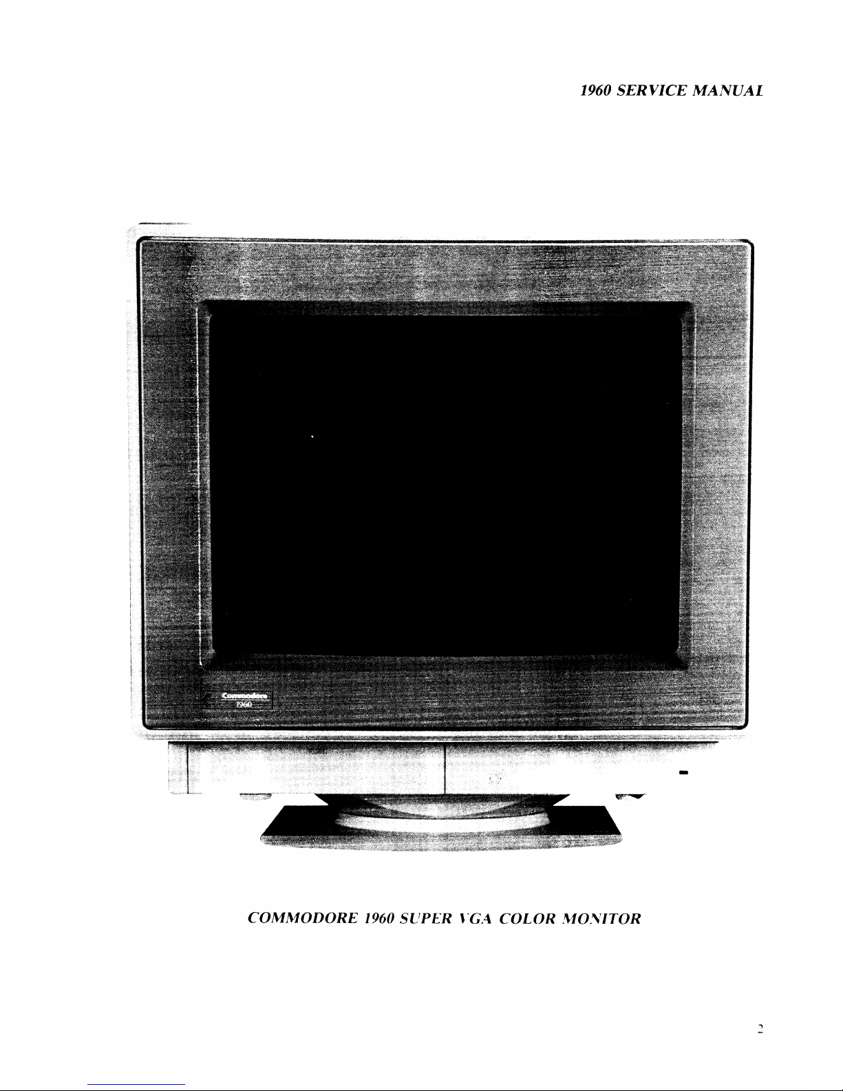
COMMODORE 1960 SUPER VGA COLOR MONITOR

1960 SERVICE MANUAL
Service Controls:
Environmental
Conditions:
Dimensions:
PWB-1011: R-BKG, G-BKG, B-BKG ,
R-Bias, G-Bias, B-Bias.
PWB-1015: G1 Voltage Adjust.,
Pincushion, Horiz. Width, Horiz. Hold \,
Horiz. Hold 2, Horiz. Phase 1, Horiz. Phase 2,
Vert. Size, Vert. Center, Vert. Linearity,
Vert. Hold, Screen.
Operation: 10 to 35 degrees C ambient.
Storage: 0 to 65 degrees C ambient.
Humidity: 8% to 80% (non-condensing).
Altitude: up to 7000 ft. above sea-level.
388mm (H) x 370mm (W) x 420mm (D).
Gross Weight: 14 kgs.
SIGNAL CABLE PIN CONNECTIONS
Analog:
Pin
Signal
Pin
Signal
1
Red Signal
8 Blue Return
2
Green Signal
9 No Pin
3
Blue Signal
10 Digital Ground
4
Monitor Sense
11 Jumper to Pin 10
Ground to Pin 10
12
No Pin
5
Ground
13 Horizontal Sync.
6
Red Return
14
Vertical Sync.
7
Green Return
15 Jumper to Pin 10
TTL:
Pin
Signal
Pin Signal
1
Ground
6
Green Prime
2
Red Prime
7
Blue Prime
3
Red Signal
8
H Sync
4
5
Green Signal
Blue Signal
9
V Sync
3
I960 SERVICE MANUAL
SAFETY PRECAUTIONS AND NOTICES
SAFETY PRECAUTIONS
1. Observe all cautions and safety related notes located inside the monitor cabinet
and on the monitor chassis.
2. Operation of the monitor outside its cabinet or with the cover removed involves
the risk of shock from the monitor power supply. Repair work on the monitor
should not be attempted by anyone who is not thoroughly familiar with all
necessary safety precautions and procedures for working on high voltage
equipment.
3. Do not install, remove, or handle the picture tube in any manner unless shatter
proof goggles are worn. People not so equipped should be kept at a distance
during handling of the picture tube. Keep the picture tube away from the body
during handling.
4. The picture tube is constructed to limit X-radiation to 0.5mR/HR at 300 micro
amperes anode current. For continued protection, use the recommended
replacement tube only, and adjust the voltages so that the designated maximum
rating at the anode will not be exceeded.
PRODUCT SAFETY NOTICE
Many electrical and mechanical parts in this chassis have been specially inspected
for safety, and the protection afforded by them cannot necessarily be obtained by
using replacement components rated for higher voltage, wattage etc. Before
replacing any of these components, read the Spare Parts List at the end of this
manual carefully. The use of substitute replacement parts which do not have the
same safety characteristics as those specified in the Spare Parts List may result in
shock, fire, X-radiation or other hazards. »
4

1960 SERVICE MANUAL
SERVICE NOTES
1. When replacing parts or circuit boards, clamp the lead wires around the terminals
before soldering.
2. When replacing a high wattage resistor ( >0.5 W metal oxide film resistor) in the
circuit board, keep the resistor about 1 cm (1/2") away from the circuit board.
3. Keep wires away from high voltage or high temperature components.
4. Keep wires in their original positions so as to minimize inteference.
SAFETY TEST
Before returning a serviced monitor to the customer, a thorough safety test must be
performed to verify that the monitor is safe to operate without danger of shock.
Always perform an AC current leakage check on the exposed metallic parts, such as
screw heads, as follows:
1. Plug the AC line cord directly into a rated AC. Do not use a Line Isolation
Transformer during this check).
2. Use an AC voltmeter having at least 5000 ohms per volt sensitivity as follows:
Connect a 1500 ohms 10 watt resistor, paralleled by a 0.15mfd, AC type capacitor
between a known good earth ground (such as a water pipe or conduit etc.) and the
exposed metallic part simultaneously. Measure the AC voltage across the
combination of 1500 ohms resistor and 0.15mfd capacitor.
3. Reverse the AC plug at the AC outlet and repeat the steps for AC voltage
measurements for each exposed metallic part.
4. Voltage measured must not exceed 0.3 volts RMS. This corresponds to 0.2
milli-amps AC. Any value exceeding this limit constitutes a potential shock hazard
and must be corrected immediately.
To good earth ground
To exposed metallic
/ Part
1500 ohm
10 watt
5
 Loading...