

Page 1

Page 2
IMPORTANT
SAFEGUARDS
I.
Read
nil (if
ihot
2.
Save
for
Iflier
use.
3.
Unplug
this
monitor
from
the
wall
outtfl
before
cleaning.Donoi use
Yt-
quid
cleanersuraerosol
cleaners.
Use
.1
damp
cloth
for
cleaning.
4
Do
mil
use
;tll;ichniciils
HOI
recommendedhythe
monitor
iiiaiiubtiiirer
a-i
they
may
cause
hazards.
5,Donoi useMmmonitor
water
for
example,
near
.1
biiihUiti,
nn^hbuwl,
kitchen
>iriL,orJauudri
itib.
inawcl
bastrllicni,
or near a
swimming
pool,
etc.
d.Donot
place
this
moniiur
on an
unstable
carl,
siand,oruble.
The
monitor
may
fail,
causing
-.::■.-■
in
jury ionchildoradult
and
wnous
dunji'i'u>the
appliance.
7.
Slot*
anil
openingsinrhe cabinet
and
slit
hackorboitom
arc
provided
for
tcm&uiwi.
andtoensure
reliable
iipcfJiionofllie
monitor
and[uprO-
:l-,:■:frum
Dierheuiine,
[hew
open-
ings
rmtsinmbe
blov'ktdorcovered.
The
openings
shuuld
neverbeblockedbyplacing
Lhc
nionLlor
on
a
bed,
sofa,
rut:,mother
Miniliir
surface.
This
should
nc^rrbeplaced
nearOfoveraradiatororheal
register.
TMs
monitor
shuuM
noihupht-wlina
built-in
in-
s[all:iikin
sucha\a
tttefccase
unless
proper
venlfla
linnisprovided.
K.1Ills
monilur
shouldbeopeiated
only
from
Hie-
type:ofpo*er
source
edonrht
marking
liibcl.Ifyou
c
not
surenlilic
power
supplied
io
your
home,
consult
yuur
monitor
dealerorlocal
poww
company-
y.
Iliis
iiKHiito:isequipped
with
a
t-wfee
gtoundim;
[ypc
plug,aplug
havingaIhiivl
(^rounclini;!
pin.
This
plus
Mill
unl>
t'ir
iotaayrounding-
lype
power
miifcl.
Thisisa
safely
fratme.Ifyou
arc
unableIoi(BAft
[he
pblg
IniO
Ihf
unllcl.
wfiitittl
>(>u(
clctUiciantoreplace
your
ob-
soldc.Donot
[iv'Tcai
ihf
purpo^ofthe
grounding-
lypc
plug.
10.Dozioi
allow
anythingioresl
on
ifie
power
cmd.Donot
Ideate
ihis
muniior
whcrcihccoid
^»ill
bcabtis-
■rdhypersons
walkingonit.
II.Follow
jill
i\inning
anil
insLriic:l!Oas
mftllfd
Onlli
monitor
12.
I-or
ud<lcd
pw«tiDH
for
ihis
mnniKii
durinpaUghintng
storm,
or
wfceanis
k-fi
unauended
and
uauscd
for
[any
perioJvoflime,
unplug
.
from
Mil1
waS
outtei.
This
will
prevent
ilunuigcinllic
sei
dyttulightning
and
powcrlinc
iurjji;s.
1?.Donoi
overload
wall
nuilcis
and
extension
cords
a^
This
can
resultinfireordectrfc
shock.
14.
Never
push
objectsofany
kind
inlo
llui
monilOr
through
cabins
stol*.asthey
mu>
loach
dangerous
voltage
pointiorihtlrt
Clll
partiIlull
could
rcGutl
iti
a
fireordearie
shock.
Never
ipill
Jinnidofiuiy
kindonllic
15.Donot
atiempi10icnict:
tills
monitor
yourself
;i*
i>iwningorre-
maying
covers
may
expose
you
tw
dau^ortju1-
volumeOfOlh«
liazards
Refn
all
servicingioqualified
service
pcrMimicl.
£6.
Unplug
[hi*-
flUMUIOT
from
the
uvll
outlet
and
refer
servicingtonujlifird
KTVicc
pCTSOBTKl
widei
ihe
n.
When
ilie
frayed.
cordOrplug
b.Ifliquid
has
been
spiled
iiuo
[he
monitor.
c.Ifthe
monitor
has
been
c\pOM.\Jtorain
Bruttler.
d. If
the
monitor
does
mil
Operate
normally
by
following:
the
operating
iiistruLlkin^.
Adjust
only
throe
com
rnliIhat
arL-tovaedInilic
upenuinu
iti-
strudjasuasimproper
adjtuiraeni
of
other
coeErob
may
rt-iullindamage
and
will
oficti
require
eitcti-
sm
wwfchyn
qualified
techniciantorestore
the
mortitoc
^-iu>riormiil
opt
ration,
e.Ifthe
monttai
hoi
been
droppedordie
cabincs
has
bevn
damaged,
f.
Whfn
[he
monitor
exhibits
a
dinlnci
L-hiinjfc
in
performance
this
indicate*aneed
for
service.
17.
When
replacement
part*,were
quired,besutl"
ihe
service
lechrucian
liav
used
rt-pbti-UK-m
pans
specified
by
ihc
maiuificlurcr
Lhul
h;^c
thf
I
sane
chdmcieHsiics
as
ihc
original
1^-
part
Unituttuij-i/td
substiiuiiuns
may
r«uli
in fire,
electric
shock,
or other
^-~±J
hazards.
IS.
Upon
corapjetion
of
any
serviceorrepairstothis
monitor,
d^k
the
service
Technician
to
perform
routine
safety
checkswdctennme
ihu)
ihc
mocitotiiin
safe
□neralina
i/nndi<!(>ri.
Page 3
User's
Guide
Monitor
1940/42
r
Commodore
Page 4
Monitor
1940/1942
WARNING
Installation
information
in
this
document
is
for
reference
only.
All
in
stallation
of
internal
optional
devices
or
equipment,
including
third-
party
optional
devices
or
equipment,
should
be
performed
by
an
authorized
Commodore
dealer/service
centre.
Also,
all
servicing
or
upgrading
of
original or
optional
devices
or
equipment,
including
third-party
optional
devices
or
equipment,
should
be
performed
by
an
authorized
Commodore
dealer/service
centre.
Unauthorized
in
stallation
or
servicing
may
void
your
warranties.
This
manual
provides a
general
description
of
various
product
con
figurations
and
features
currently
planned
for
inclusion
in
Commo
dore's
product
line.
The
configurations
and
features
described
may
not
be
available
or
otherwise
apply
to
your
particular
system.
Please
consult
your
Commodore
dealer
with
any
questions.
Page 5
Monitor
1940/1942
GB-3
Introducing
your
Monitor
Your
monitor
is
full-colour,
13-inch
multi-sync
monitor
for
use
with
the
Commodore PC*
and
Amiga
family
of
computers.
The
monitor
provides
audio
output
in
stereo
for
use
with
computer
system
with
stereo
capabilities
(like
the
Amiga
computers).
This
manual
explains
how
to
connect
the
monitor
to
your
computer
and
how
to
use
the
various
operating
modes
and
picture
controls,
Before
you
proceed
any
further,
check
to
make
sure
you
have
received
everything:
•
One
monitor
with
captive video
cable.
The
free
end
of
this
cable
has
15^pin
male
connector
flanked
by
screws,
which
connect
to
your
computer's
video
port.
For
connection
to
an
Amiga's
23-pin
video
port,
a
23-
to
15-pin
adapter/buffer
should
be
used,
Commo
dore
P/N:
390682-01.
•
TiltfSwivel
Base
•
Cables;
-
For
connecting
an
Amiga's
audio
capabilities
-
one
cable
with
two
RCA
plugs
on
each
end.
-
Power
cable
for
connecting
the
monitor
to
an
AC
power
source.
•
Warranty
card
•
Display
sizeialaTger
than
normal
VGA
13"
monitor;.
Page 6

GB-4
Monitor
1940/1942
How
to
Install
or
Remove
a
Tilt/Swivel
Stand
1.
Turn
off
the
system
and
all
attached
options.
2.
Carefully
set
the
display
upside
down.
Installing
the
Tilt/Swivel
Stand
1.
Align the
stand
with the
slots
in
the
bottom
of
the
display
and
in
sert
the
Tilt/Swivel
Stand
into
the
slots.
2.
Pull
the
Tilt/Swivel
Stand
firmly
toward
the
front
of the
display
until
the
latches
click
into
the
locked
position.
.1
V
Page 7

Monitor
1940/1942
GB-5
Removing
the
Tilt/Swivel
Stand
1.
Squeeze
and
hold
the
latches.
2.
Push
the
Tilt/Swivel
Stand
to
the
back
of
the
display
and
lift
to
remove
the
stand.
Page 8
GB_6
Monitor
1940/1942
Control
Locations
and
Functions
Before
you
connect
your
monitor
to
your
computer,
you
should
famil
iarize
yourself
with
the
location
and
function
of
the
various
control
knobs,
switches,
and
ports
on both
the
front
and
rear
of
the
monitor.
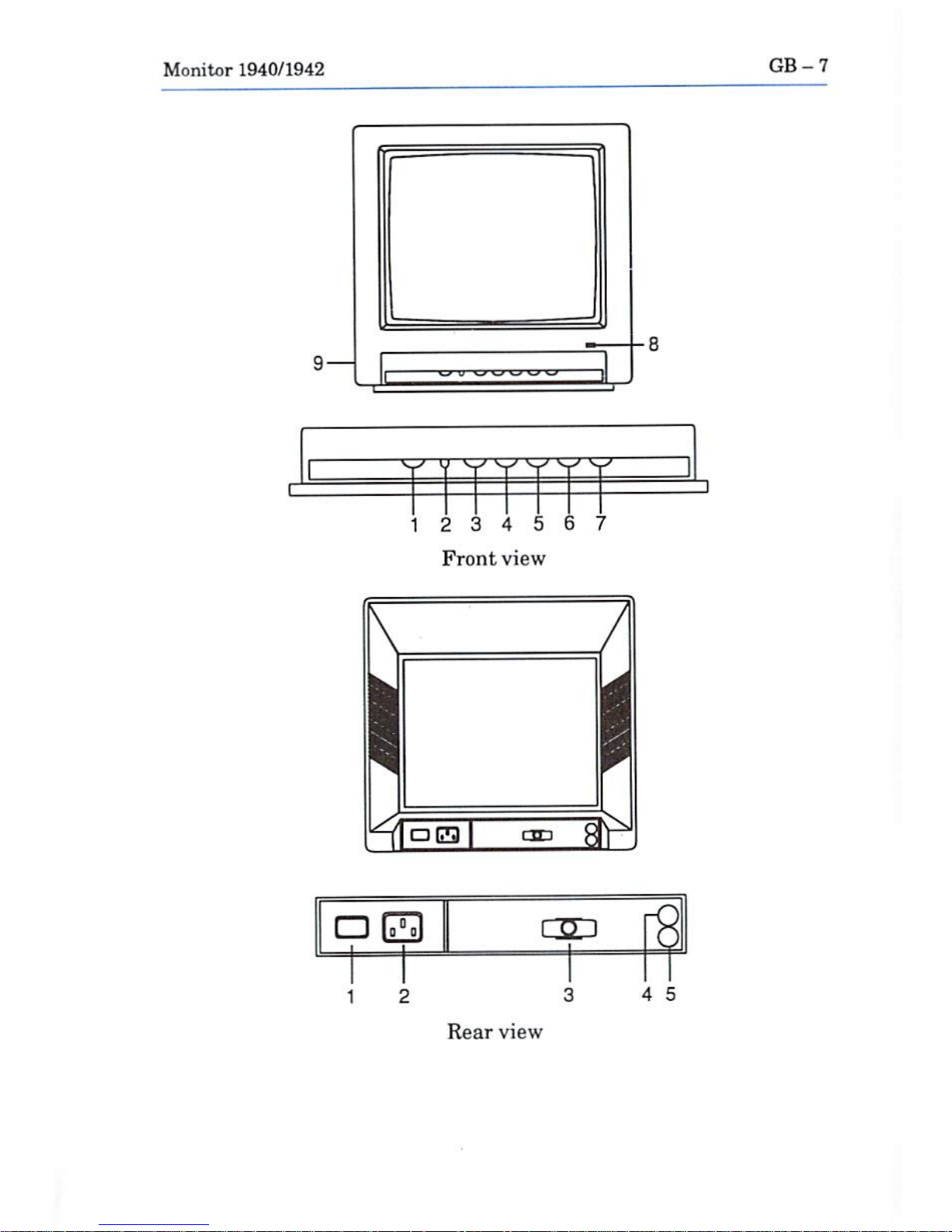
Front
View
1.
VOLUME-Adjusts
speaker
loudness.
2.
H.
WIDTH-A
switch
used
to
altenate
between
normal
image
width
and
overscan
width.
3.
VERTICAL
SIZE-Adjusts
image
height.
4.
VERTICAL
SHIFT-Adjusts
the
image
vertical
position
for
proper
centering.
5.
CONTRAST-Adjusts
display
contrast.
6.
BRIGHTNESS-Adjusts
the
brightness.
7.
H.
PHASE-Adjusts
the
image
horizontal
position
for
proper
centering.
8.
LED-Power-on
indicator.
9.
PHONE
JACK-Use
for
external
headphones.
Hear
View
1.
POWER
SWITCH
-AC
on/off.
2.
POWER
SOCKET-Power
input
terminal.
3.
RGB
CABLE-One
end
is
permanently
attached
to
the
monitor.
The
free
end
hasa15-pin
male
D-connector
which
connects
to
your
computer's
video
port.
4.
AUDIO-R-Ablack
phone
jack
used
for
connecting
the
right
audio
signal input.
5.
AUDIO-L-A
white
phono
jack
used
for
connecting
the
left
audio
signal
input.
Page 9
Monitor
1940/1942
GB-7
12
3 4 5 6 7
Front
view
OEM
12
3
4
5
Rear
view
Page 10
GB-8
Monitor
1940/1942
Connecting
the
Monitor
to
a
Computer
Turn
off
the
power
to
both the
monitor
and
the
computer
to
prevent
damage.
Unplug
the
computer
and
the
monitor
before
installation.
Installing
the
monitor
with
the
power
on
could
cause
injury
to
the
in
staller
and
damage
to
the
equipment.
Commodore
will
not
assume
responsibility
for
any
damages
caused
by
improper
installation
of
the
monitor.
Such
improper
installation
will
void
the
warranties on
both
the
computer
and
the
monitor.
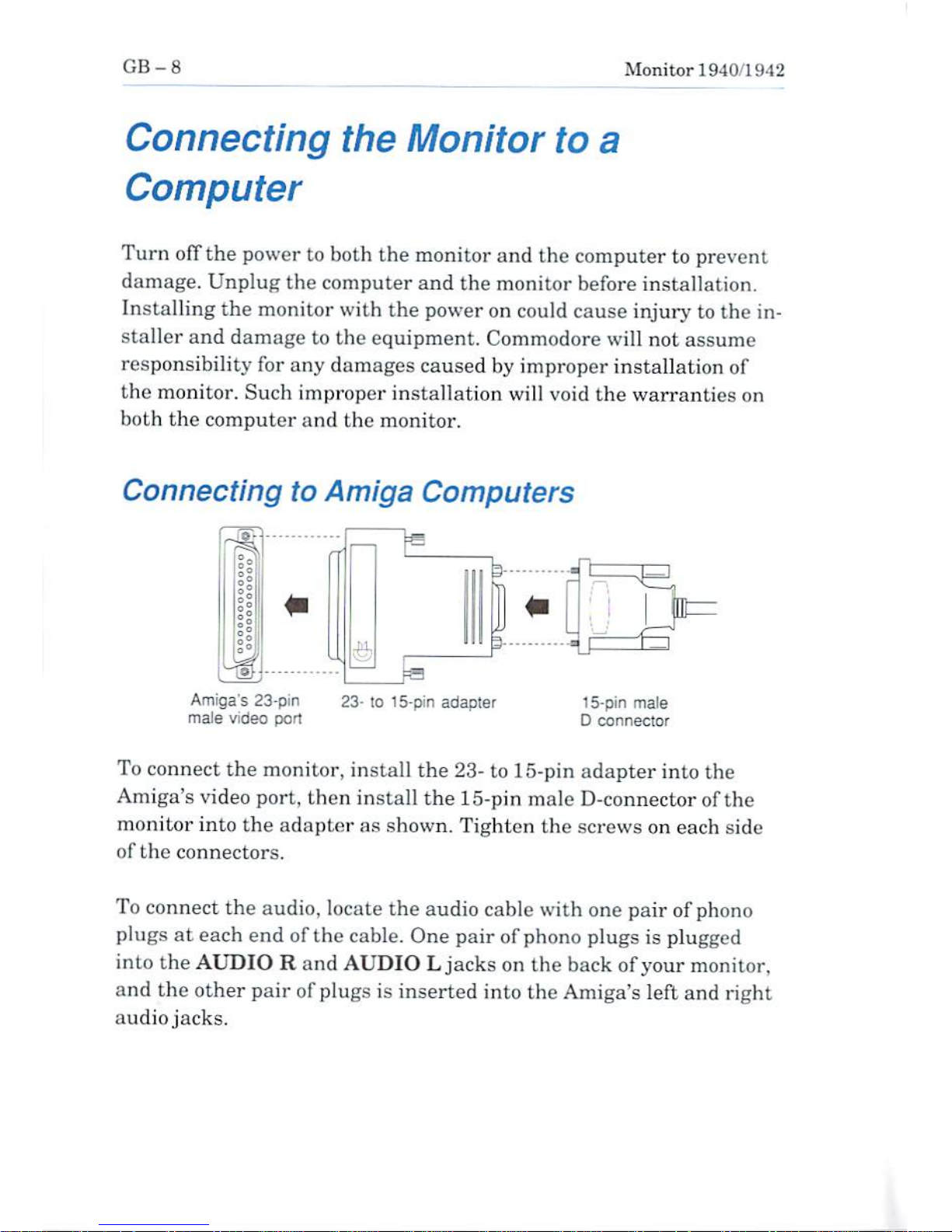
Connecting
to
Amiga
Computers
Amiga's
23-pin
maJe
video
port
lo
15-pin
adapter
15-pin
male
D
connector
To
connect
the
monitor,
install
the
23-
to
15-pin
adapter
into
the
Amiga's
video
port,
then
install
the 15-pin
male
D-connector
of
the
monitor
into
the
adapter
as
shown.
Tighten
the
screws
on
each
aide
of
the
connectors.
To
connect
the
audio,
locate
the
audio
cable
with
one
pair of
phono
plugs
at
each
end
of
the
cable.
One
pair of
phono
plugs
is
plugged
into
the
AUDIORand
AUDIOLjacks
on
the
back
of
your
monitor,
and
the
other
pair
of
plugs
is
inserted
into
the
Amiga's
left
and
right
audio
jacks.
Page 11
Monitor
1940/1942
GB-y
You
can
connect
headphones
to
your
monitor
so
that
stereo
sounds
generated
by your
Amiga
computer
can
only be
heard
through
the
headset.
To
do
this,
simply
insert
the
plug
on
the
end
ofastandard
headphone
cable
into
the
small
port
on
the
left
side of
the
monitor.
Headphones
are
not
included
with your
monitor
but
should be
read
ily
available
at
most
computer
and
electronics
stores.
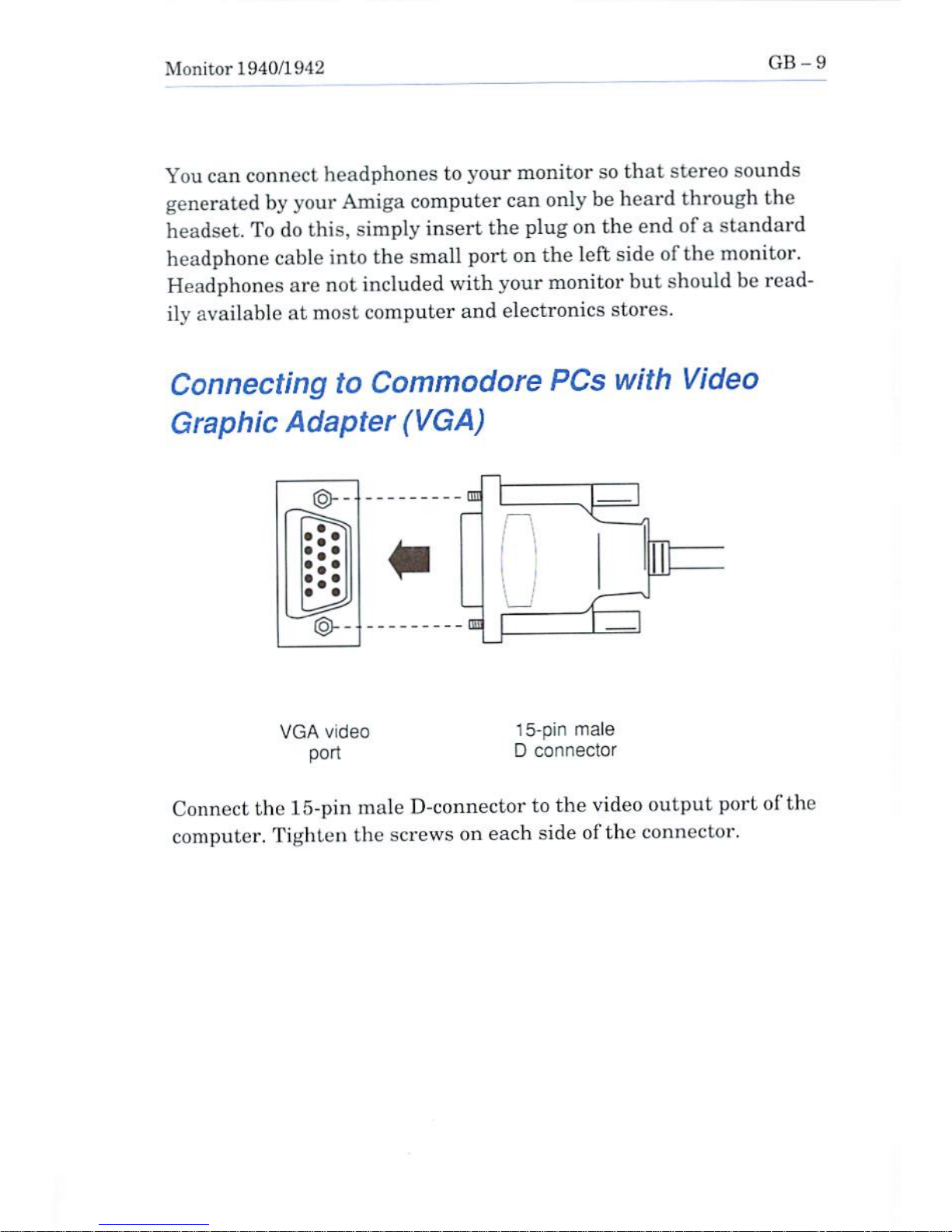
Connecting
to
Commodore
PCs
with
Video
Graphic
Adapter
(VGA)
ED
VGA
video
port
15-pin
male
D
connector
Connect
the
15-pin
male
D-connector
to
the
video
output
port of
the
computer.
Tighten
the
screws
on
each
side of
the
connector.
Page 12
GB-10
Monitor
1940/1942
Safety
Precautions
This
monitor
has
been
engineered
and
manufactured
to
assure
your
personal
safety.
However,
improper
use
can
result
in
potential
electric
shock
or
fire
hazards.
Please
observe
the
following
basic
rules
when
using
your
monitor.
Also,
heed
all
warnings
and
instructions
marked
on
the
monitor's
cabinet.
Do
not
attempt
to
service
the
monitor
yourself.
Opening
or
re
moving
covers
may
expose
you
to
dangerous
voltages
or
other
hazards.
Dangerous
high
voltage
is
present
even
when
the
monitor
is
unpl
ugged.
Refer
all
servicing
to
qualified
personnel.
Do
not
overload
AC
outlets
or
extension
cords.
This
may
result
in
a
shock
or
lire
hazard.
Do
not
use
more
than
one
plug
adaptor
in
one
power
outlet.
Do
not
use
the
monitor
near
water
or
excessive
moisture.
Do
not
block
the
monitor's
ventilation
slots
by
placing
objects
on
top
or
underneath
the
monitor.
Do
not
place
the
monitor
•
ina"built-in"
enclusure
unless
proper
ventilation
is
provided
•
near
or
overaradiator
or
heat
register
•
where
sunlight
or
bright
room
light
will
fall
directly
on
the
screen
•
on a
sloping
shelf
or
try
to
mount
it
on a
wall.
Page 13
Monitor
1940/1942
GB-11
Do
not
use
alcohol,
ammonia-based
products,
or
an
aerosol
spray
to
clean
the
monitor
screen.
To dean
the
screen,
unplug
the
monitor
and
wipe
withaslightly
damp
cloth.
Do
not
bring
magnetic
devices
near
the
screen.
They
may
damage
the
colour
purity
of
the
picture.
Unplug
the
monitor
•
if
you
will
not
be
using
it
for
an
extended
period
• during
an
electrical
storm
•
before
cleaning
it
Technical
Specifications
Your
monitor's
technical
specifications
are
listed
below.
These
speci
fications
are
subject
to
change
without
notice
as
required
by
product
improvement.
CRT
size
14"
(90*)
(13"
viewing
area)
Dot
pitch
0.39
mm
dot
matrix
(1940)
0.28
mm
dot
matrix
(1942)
Scanning
Frequency
Horizontal
15.6-15.8
Khz
27.3-31.5
Khz
Vertical
47-75
Hz
Page 14

GB-12
Monitor
1940/1942
Signal
Input
RGB/Analog,
Separate
sync
Input
Signal
Voltage
0.7Vp-p
RGB
TTL
level,
H/V
sync
Sound
Output
LOW
RMS/Channel
at
5%
max,
THD
Audio
Input
Signal
177
mV
RMS,
10
Kohm
Main
Voltage*
120
VAC
+/-10%,
60
Hz
Dr
220-240
VAC
+/-10%,
50
Hz
Power
Consumption
, ,
75Wtypical
Dimensions
3(58
(H)x325
(W)x376
(D)
mm
(with
Stand)
Weight
11.4
kg
(with
Stand)
•
Che*k mting
lubclaCthe
backofmonitor.
Page 15
Monitor
1940/1942
GB-13
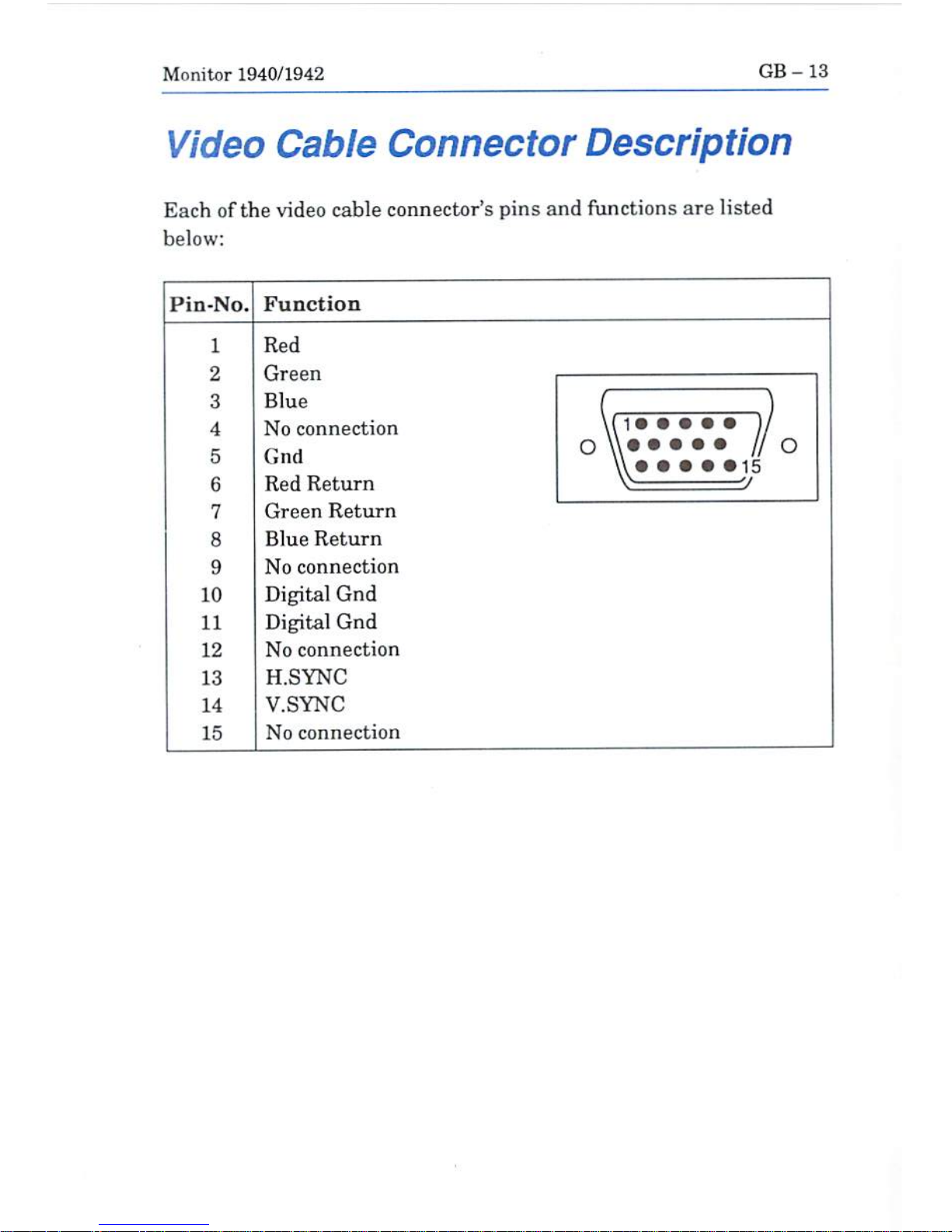
Video
Cable
Connector
Description
Each
of
the
video
cable
connector's
pins
and
functions
are
listed
below:
Pin-No.
1
2
3
4
5
6
7
8
9
10
11
12
13
14
15
Function
Red
Green
Blue
No
connection
Giid
Red
Return
Green
Return
Blue
Return
No
connection
Digital
Gnd
Digital
Gnd
No
connection
H.SYNC
V.SYNC
No
connection
(,
J
o
\\«
• •••
l/o
\\•••••15
V
V
Page 16

Page 17
Benutzerhandbuch
Monitor
1940/42
C=
Commodore
Page 18
WICHTIGE
iNFORMATfONEN
Bitte
lesen
Sie
alle
diese
lnformationenh
bevor
Sie
das
GeratinBetrieb
nehmenl
Lesen
Sie
sich
aufrerdem
die
Bedienungsanleitung
komplett
und
sorgfaltig
durch,danurindiesem
Fall
eine
problemlose
Inbetriebnahme
erwartet
werden
kann.
-
Achten
Sie
darauf,
da6 das
Gerat
nurfneine
230V
(220V)
Schuko-
Steckdose
eingesteckt
wird.
—
Die
Steckdose
sollte
jederzeit
frei
zugangltch
sein
urn
bei
einem
evtE.
auftretenden
NotfaN
das
Gerat
schnell
vom
Netzzutrennen.
—
Achten
Sie
desweiteren
darauf,
daft
die
NetzanschluBteitung
nicht
mechanisch
beansprucht
oder
sonstwie
beschadtgt
wird.
—
Offnen
Sie
das
Gerat
menials!ImInneren
befinden
sich
Teile
mit
gefahrlicher
Spannung.
—
Bevor
Sie
das
Gerat
reinigen,
ztehen
Sie
bitte
den
Netzstecker
aus
der
Steckdose.
Saubern
Sie
dann
das
Gerat
mit
einem
feuchten
(keinesfalls
tropfnassen)
Lappen.
—
Stellen
Sie
das
Gerataneinem
ergonomisch
gunstigen
Ort
auf
und
sorgen
Sie
dafur,
da5
der
Monitor
mit
nach
ZH1/618/10.B0
geprutter
Peripherie
betrieben
wird,danur
unter
diesen
Umstanden
ein
op-
timaler
ergonamischer
Betrieb
des
Gerates
sichergestellt
ist.
Falls
Sie
dennoch
Fragen
haben,
aul
die
die
Bedienungsanleitung
keine
h^nreichende
Anlwort
geben
kann,sokontaktieren Sie
bitte
den
nachsten
Fachhandler.
Maschinenlarminiormationsverordnung
3.
GSGV,
13.01
1991:
Der
arbeitsplatebezogene
Schalldruckpegel
betragt70dB
(A)
oder
weniger
gema&
ISO
7779.
Page 19

Monitor
1940/1942
D-
1
Copyright©1992
Coramodcre
Electronics
Limited.
Allfi
Ftachte
vorbehatten.
Ohnc
vcrhcrigc
schriftliche
Zustimmung
von
Commodore
darf
dieses
Document
wederganz
noch
l.-i1w.
i*r
ftopiert,
fo-
tokapiert,
reproduricrt,
(ibrnetzt
oderinetefctronisch
oder
ma&chinell
lesbare
Form
gebrachi
In
ditst'in
Dakument
enthaltene
Bcschrcibungcn
dcr
J*rodukter
ihrer
Punktioaa
weise,
p
tftt
oder
Verfilgbarkeit
dilrfen
weder
ala
ausdrtlcklich
noch
ala
3ti)lschwagend
geltende
Gew
stiinj;
Oder
Garantie
inteTpretiOTt
mrden.
Commodore
ybcmintmt
keine
VenintwortiLng
odcr
HafllAng
fttr
von
Commudare
oderCommndores
ErfiUliingagchiircngcmachtc
odcrin
hicrvon
nach-
gednicklcn
VeriiflenUichungEn
entholtene
Angaben
oder
Krklfeningen.
E1NE
SCHADENERSATZ-
PFLICHT
ECANN
UNTERKEINEN
UMSTANDEN
FUH
DlREhTTE,
INI>[REKTE,
ZUFALLIGE
SCHADEN
ODER
FOLGESCHADEN
OELTEND
GBMACHT
WERDEN,
DIE
AUFGRUND
IN
DIESEM
DOKUMENT
ENTHALTENER
ERKLARUNGEN
ENTSTANDEN
SIND,
SELBST
WENN
AUF
DIE
MOGLJCHKEIT
DEEiARTIGER
SCHADEN
HINGEWIESEN
WORDEN
1ST,
EINIGE
LANDER
GESTATTEN
DEN
AUSSCHLLTSS
ODER
DIE
BEGRENZUNC
DERARTIGER
GEWAHItLEISTUNGEN
ODER
SCHADENERSATZPFLICHT
NIGHT,SODAES0.G.
AUS-
SCHLUSS
ODER
BEGREN'ZUNOINDIESEN
I^NDERN
MOGLICHERWEISE
N1CHT
GELTEN.
Comraodcirc
Logo
aindinden
USA
un<l
vielcn
anderen
Landern
eingetragsne
i'n
dcrCominodDre
EEectrojiica,
Ltd,
Amiga
istindpn
USA
ujidvielea
anderen
Ltindern
ein
eingctragrjnfia
Warenzeichen
van
Commodore-Amiga
Inc.
VGA
ist
ejn
iri
d(?rt
USA
Und
vfrfen
andcren
Lundcmcingetragenes
Warenztichttn
dur
Intematio
naJ
Bvisincaa
Machines
Corporation.
Page 20
D-2
Monitor
IU40/1942
ACHTUNG
Die
in
dicscm
Document
aufgeftihrten
Einbauhinweiae
sind
aus-
schliefllich
fiir
NachschHigezwecke
vorgesehen.
Der
Einbau
von
Zu-
satzgeralcn
und
Erweiteningen
-
oinschlielilich
der
Zusatzgerate
und
ErweiUn'ungen
von
Fremdberst^Ilern
-
sollie
nur
durch
einen
autori-
sierten
Commodore-Amiga-H<indler
erfolgen.
Ebenso
miissun
Service-
Arbeiten
an
Grundgeraten,
Zusatzgeraten
und
Erweiterungen
-
ein-
schlieBlicb
der
ZusatzgenilG
und
Erweiterungen
von
Frcrndberstel-
lern-von
einem
autorisierten
Gommodore-ServicG-Center
oder
einem
autorisierten
Conimmodore-Amiga-Handler
durchgefiihrt
werden.
Unbefugte
Einbau-
oder
Service-Arbeiten
fiihren
unter
Umstanden
zum
Garantieverlust.
Das
vorliegende
Handbuch
gibt
einen
allgemeinen
Uberblick
liber
verschiedcne
Produktkonfigurationen
and
Zusatzfunktionen,
die
in
die
Produkireihe
von
Commodore
aufgenomntcn
werden
sollen.
Die
genannten
Koniigurationen
und
Zusatzfunkuonon
sind
mdgHcber-
weise
nicht
alle
verfitgbar
oder
wirken
sich
in
\ersehiedenen
Syste-
men
untcrschiedlich
aus.
Nalicres hierzu
kanii
heim
zuaLtindigen
Com-
modoro-Amigfi-Handlererfragt
werden.
Page 21
Monitor
1940/1942
D-3
1.
Einfuhrung
Der
Monitor
1st
ein
Farbmonitor
(13
Zoll),
der
an
einen
Commodore
PC*
oder
einen
Amiga
angeschlossen
werden
kann.
Der
Monitor
verfugt
auch
iiber
Audioanschliisse
fiir
Stereoausgabe.
iiber
die
der
Monitor
an
einen
Rechner
mit
entsprechenden
Audioausgiingen
(z.
B.
Amiga)
angeschlossen
werden
kann.
In
diescm
Handbuch
wird
be-
schricben.
wie
der
Monitor
an
einen
Computer
angeschlossen
wird
und
wie
die
verschiedenen
BoLriebsmodi
und
Bildeinstellrcgler
ver-
wondet
werden.
Bevor
Sie
mit
dcm
Aufstelien
foitfahren,
sollten
Sie
den
Lieferumfang
Lihcrprufen.
Zum
Lieferumfang
gehdren:
•
Ein
Monitor
mit
Videoanridiluflkabel,
Dieser
Monitor
wird
iiber
einen
ISpoligcn
Stecker,
der
rait
Befesttgungsschrauben
versehen
ist,
an
die
Videobuchse
des
Rechners
angeschlossen.
Fiir
don
An-
schluG des
Monitors
an
die
23polige
Videobuchse
eines
Amiga
ist
ein
23-auf-15-Pol-Adapler
(Commodore
Teilenummer:
390682-01)
erforderlich.
•
Dreh-/Schwenkfu6
•
Kabel:
-
Zurn
Anschliefien
an
Audiogerate:
Ein
Kabel
mit
Cinch-Steckem.
-
Ein
Netzkabel
zum
AnschlieBen
dea
Monitors
an das
Netz.
•
Gewahrleisiungskarte
"
DwAnzeigebereith
tsi
prnBer
alsbci
normtilpn
13-ZoU-VOA-Monitoren.
Page 22
D-4
Monitor
1940/1942
2.
Montieren
und
Entfemen
des
Dreh-fSchwenkfusses
1.
Schalten
Sie
das
System
und
alle
angeschlossenen
Peripheriege-
rate aus.
2.
Drehen
Sie
den
Monitor
vorsichtig
urn.
2.1
Montieren
des
Dreh-/Schwenkfusses
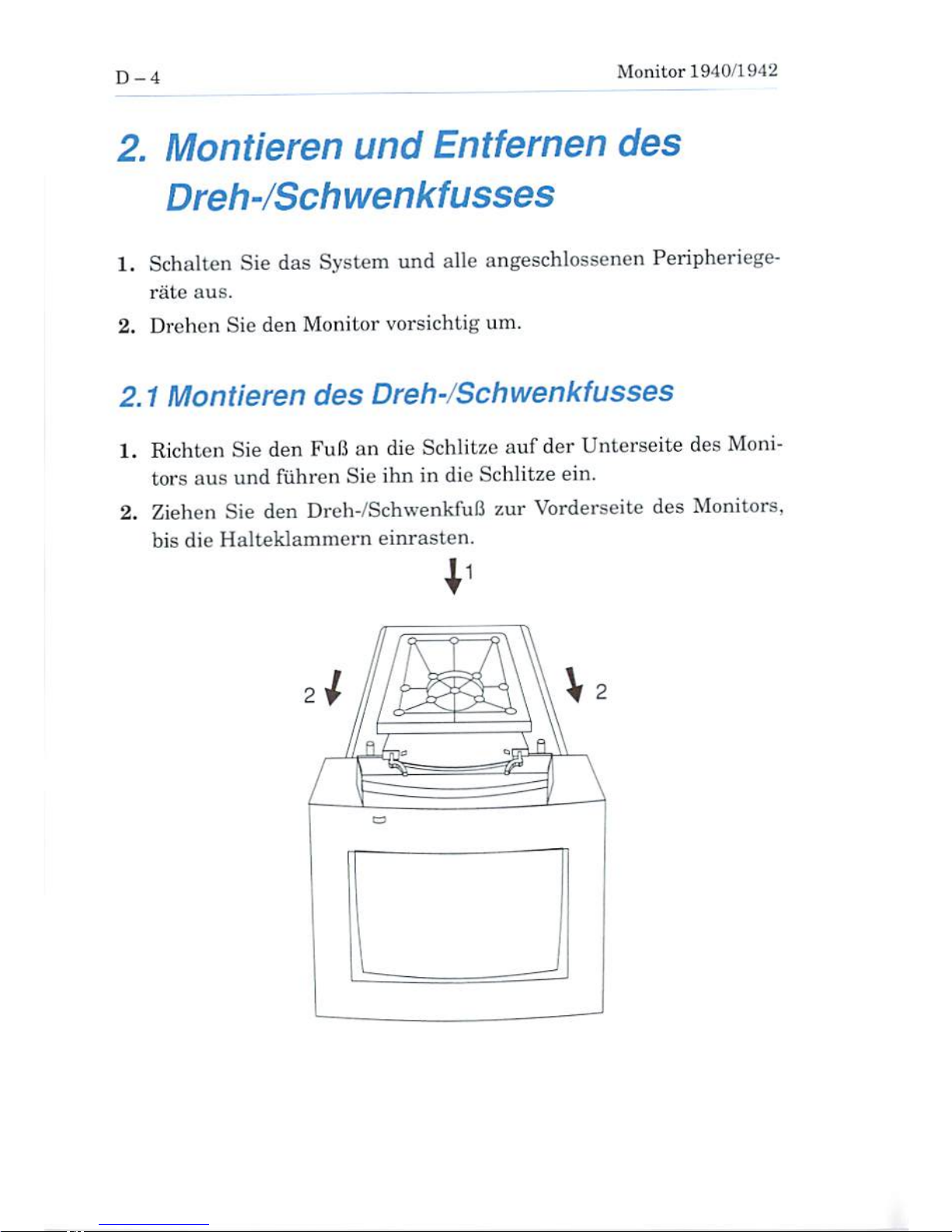
1.
Richten
Sie
den
FuB
an
die
Schlitze
auf
der
Unterseite
des
Moni
tors
aus
und
fuhren
Sie
ihn
in die
Schlitze
ein.
2.
Ziehen
Sie
den
Dreh-/SchwenkfuB
zur
Vorderseite
des Monitors,
bis die
Halteklammern
einrasten.
.1
Page 23
Monitor
1940/1942
D-5
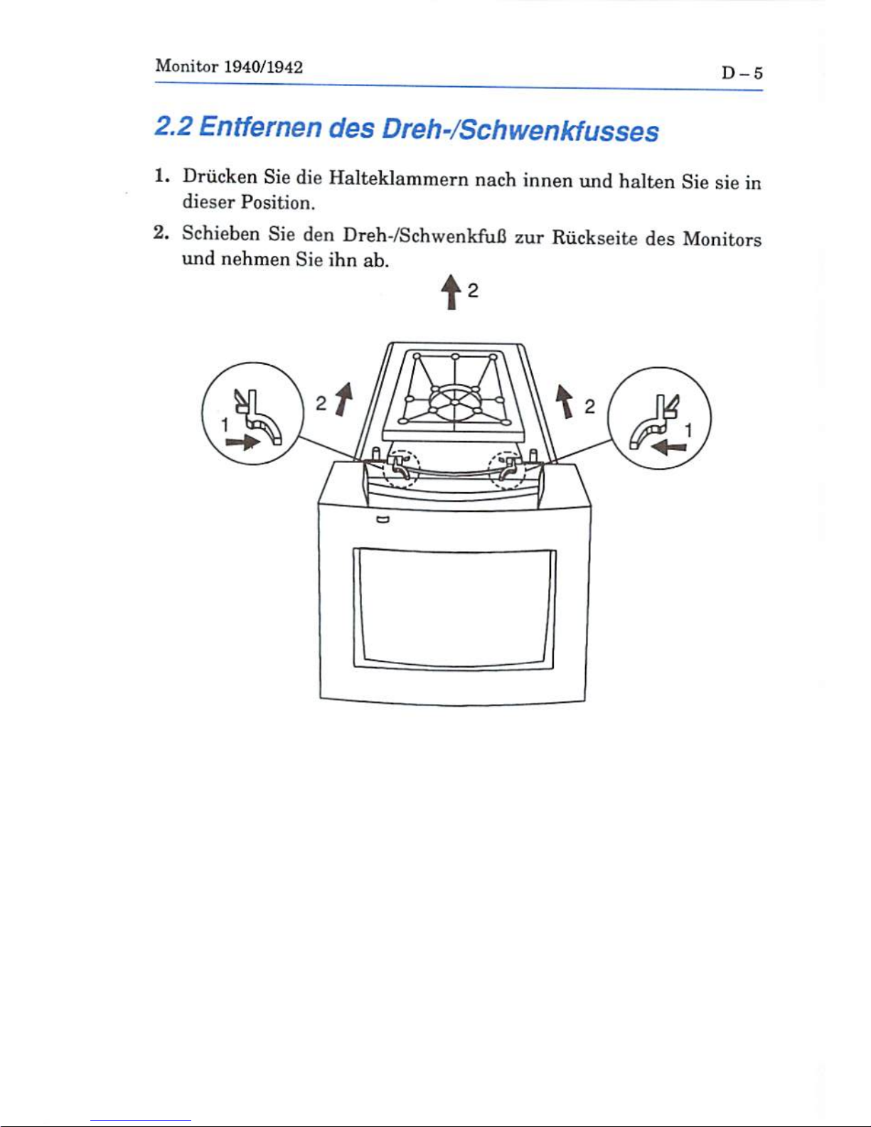
2.2
Entfernen
des
Dreh-/Schwenkfusses
1.
Driicken
Sie
die
Halteklammern
nach
innen
und
haiten
Sie
sie
in
dieser
Position.
2.
Schieben
Sie
den
Dreh-/SchwenkfuB
zur
Riickseite
des
Monitors
und
nehmen
Sie
ihn
ab.
Page 24
Monitor
1940/1942
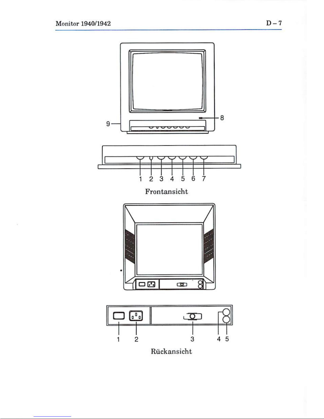
3.
Bedienelemente
und
Funktionen
Bevor
Sie
den
Monitor
an
Ihren
Computer
anschliefien,
sollten
Sie
sich
mil
Position
and
Funktion
der
verschiedenen
Bedienelemente.
Schalter
und
Anschliisse
an
der
Vorder-
und
Ruckseite
des
Monitors
verirautmachcn.
Frontansicht
1.
VOLUME-Einstellen
der
Lautstarke,
2.
H,
WIDTH-Schalter
sum
Wechseln
zmschen
normaler
BiLdbreite
and
Randbereichsbreite
{Overscan).
3.
VERTICAL
SIZE-Sinsteilen
der Bildhohe.
4.
VERTICAL
SHIFT-Zentrieren
des
Bildes
(vertikal).
5.
CONTRAST-EinsteUtn
des
Kontrastes.
6.
BRIGHTNESS-Einstellen
der
Helligkeit.
7.
H.
PHASE-Zentrieren des Bildes
(horizontal).
8.
LED-Netzkontrolleuchte.
9.
PHONE
JACK-AnschluG
fur
externe
Kopfhorer.
Riickansicht
1.
POWDER
SWITCH-Netzschalter
2.
POW^R
SOCKET-Netzanschlufl
3.
RGB
CABLE-(VideoanschluBkabel)
Ein
Ende
1st
fest
mit
dem
Monitor
verbunden.
Das
Treie
Ende
verfugt
tiber
einen
lopoligen
Submin-D-Steckor,
der
an
die
Viricobuchse
des
Computers
ange-
achloseeB
wird.
4.
AUDIO-R-Eine
selnvarze
Cinch-Buchse
fur
das
recbte
Audio-
Eingangssi^nal.
5.
AUDIO-L-Eine
weiBu
Cinch-Buchse
far
das
linke
Audio-
Page 25
Monitor
1940/1942
D-7
9
—
12
3 4 5 6
7
Frontansicht
□
ra
12
3
4
5
Riickansicht
Page 26

D-8
Monitor
1940/1942
4.
Anschliefien
des
Monitors
an
einen
Computer
SchaHen
Sic
zum
Anschlieflen
Monitor
und
Computer
aus,
urn
Schaden
zu
vermeiden.
Trennen
Sie
Monitor
und
Computer
vom
Xetz.
AndernfalU
konnen
Unfalle
durch
Stromschlage
odcr
Schaden
am
Geriit
auftreten.
Commodore
ubernimmt
keine
Haftung
fur
Schiiden.
die
auf
eine
unsachgema.Be
Vorgehonsweise
zurUckzuftih-
ren
sind.
Unsachgcmiific
Vorgehensweise
beim
Aufstellen
fuhrt
zum
Garantieverlust
fur
den
Computer
und
den
Monitor.
Anschliefien
an
Amiga-Computer
^
23potiger
VideostecKer
de&
Amiga
23-zv15-Pol-Adapter
iSpoliger
SubmirDStecker
Stecken
Sie
zum
AnschlieJ^en
des
Monitors
zunfichst
den
23-auf-15-
Pol-Adapter
in
den
VideoanschluB
des
Amiga.
Anschliefiend
stecken
Sie
den
lopoiigen
Submin-D-Sfceeker
in
den
Adapter
(siehe
AbbildungJ.
Ziehen
Sie
die
seitlich
angeordneten
Befestigungsschrauben
an.
Nehmen
Sie
fur
die
Tonverbindung
das
Audiakabel
mit
den
Cinch-
Steckern
zur
Hand.
Stecken
Sie
oin
Steckerpaar
in
die
mit
AUDIO
R
und
AUDIOL(Riickseite
des
Monitors)
gekennzcichneten
Buchsen.
Stecken
Sie
das
andere
Paar
in
die
rechte
und
linke
Audio-Buchse
des
Amiga.
Page 27
Monitor1940/1942
D-9
4.1.1
Anschliefien
von
Kopfhorern
An
den
Monitor
konnen
Kopfhorer
angeschlossen
werden.
Dadurch
konncn
vom
Amiga
ausgegebenc
Stereo-Tcine
iiber
Kopfhorer
abge-
hort
werden.
Zum
AnschlieBen
miissen
Sie
den
Stecker
am
Ende
des
Standardkopfhorerkabels
in
die
kleine
Buchse
an
der linken
Seite
des
Monitors
anschlieUen.
Kopfhorer
gehiiren
nicht
zum
Lieferum-
fang.
Sie
sind jedoch
in
den
meisten
Computer-
und
Elektrofachge-
schaften
erhaltlich.
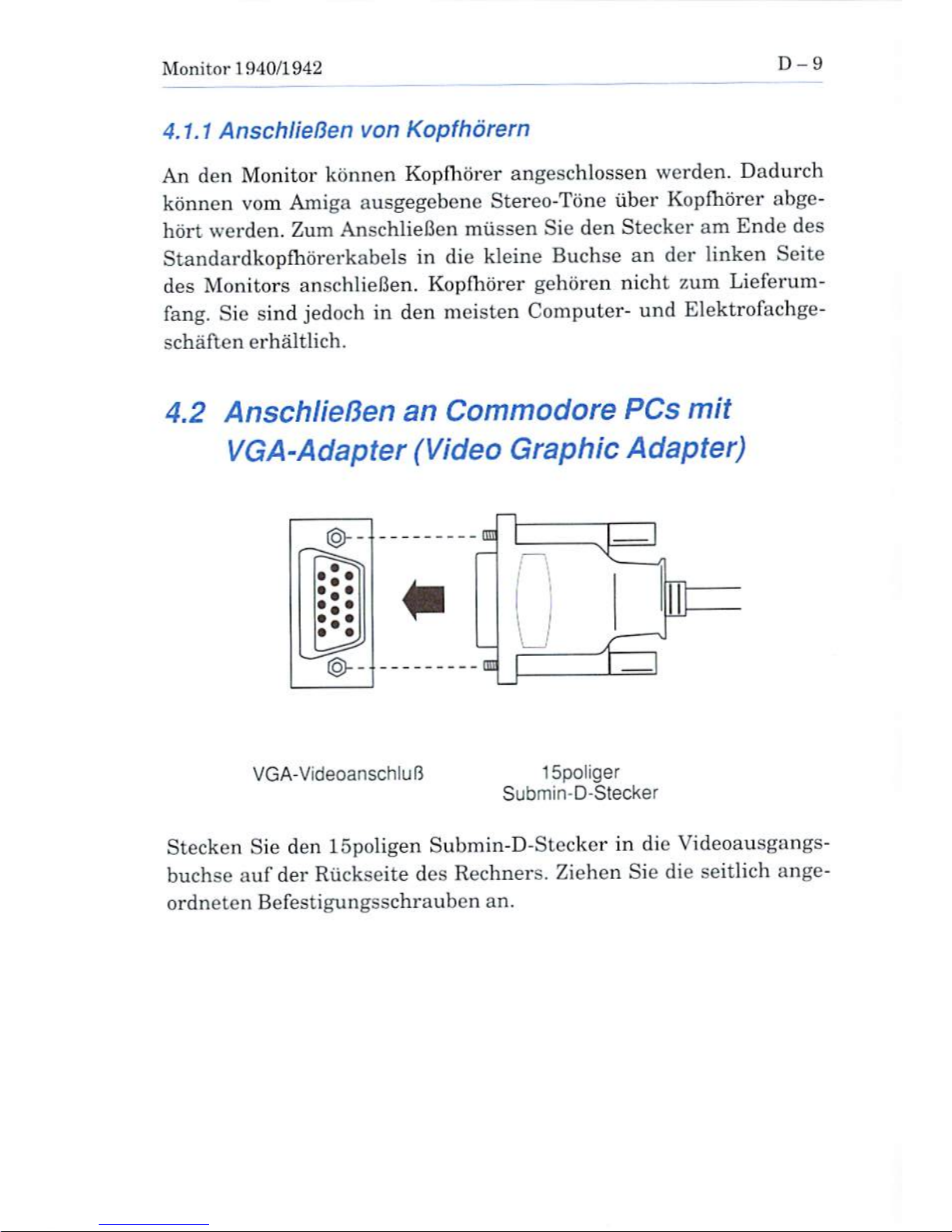
4.2
AnschlieBen
an
Commodore
PCs
mit
VGA-Adapter
(Video
Graphic
Adapter)
-
EH
VGA-VideoanschliiR
15poliger
Submin-D-Stecker
Stecken
Sie
den
15poligen
Submin-D-Stecker
in die
Videoausgangs-
buchse
auf
der
Riickseite
des
Rechners.
Ziehen
Sie
die
seitlich
ange-
ordneten
Befestigungsschrauben
an.
Page 28
D-10
Mogitar
1940/1942
5.
Sicherheitshinweise
Der
Monitor
ist
so
konstruiert,
dafl
Unftille
gnindsBtzlich
ausge-
schlossen
sind.
UnKachgemaJ3e
Handhabung
kann
jedocfc
zu
Kurz-
schllissen
fiihren,
Beachten
Sie
bei
der
Arbeit
mit
(hrera
Monitor
die
folgenden
Regeln.
Beachten
Sie
auch
alle
Warnungen
und
Hinwcisc
am
Monitor.
Versuchen
Sie
nicht,
den
Monitor
selbst
zu
warten.
Beim
Offnen
des
Gehauses
besteht
ggf.
die
Gefahr
von
elektrischen
Schlii^en. Selbst
wenn
dor
Monitor
nicht
an
das
Neta
ange-
schlossen
ist,
liegt
evtl.
Hochspannung
an.
Daher
sollten
Sie
alle
Wartungsarbeiten
qualifT/iertemFachpersonal
uberlassen.
Vermeiden
Sie
eine
Uberlastung
des
HLroranetzes.
Dies
kann
2u
n
fuhren.
Verwenden
Sie
maximal
cintMi
Mehrfachstccker
pro
Wandsteckdo.se.
Vermeiden
Sie
FouchtigkeiL
Die
Litftungsschlitze
des
Monitors
diirfen
nicht
abgedeckt
werden.
Folgetido
Punkte
sind
bei
der
Auawahl
des
Standorts
des
Moni
tors
von
Bedeutung:
•
Eine
gute
Beliiftung
mufi
gewfthrleistet
sein.
•
Der
Monitor
darf
nicht
neben
Warmequellen
(Heizung)
aufge-
stellt
wevden.
• DirckterLichteinfeli
ist
zu
vermeiden.
•
Der
Monitor
mufi
auf
einerstabilen,
ebenen
Flache
aufgestellt
werden.
Page 29
Monitor
1940/1942
D-ll
Verwenden
Sie
zum
Reinigen
des
Monitors
nur
schonende
Reini-
gungsmittel
(kein
Alkohol,
Ammoniak
etc.).
Trennen
Sie
zum
Reini
gen den
Monitor
vom
Netz
und
wischen
Sie
ih*n
mit
einem
feuchten
Tuch
ab.
Sie
den
Monitor
keinen
Magnetfeldern
(groBe
Trafos
oder
Elektromatore)
aus.
Magnetfelder wirken
sich
negativ
auf
die
Farb-
anzeige
aus.
Der
Monitor
muB
in
folgenden
Fallen
vom
Netzgetrennt
werden:
•
Bei
langerer
Aufierbetriebnahme
•
Bei
Gewitter
•
Vordem
Reinigen
6.
Technische
Daten
In
der
folgenden
Tabelle
sind
die
technischen
Daten
Ihres
Monitors
aufgefiihrt
(Anderungen
vorbehalten.).
Grbfie
der
Bildrbhre
14
Zoll
(90'}
(1:1
7m\\
sichthartT Hereidi)
PunktgrbBe
0,39
mm
Punktmatrix
(1940)
0,28mmPunktmatrix
(1942)
Ablenkfrequenzen
Honzontal
15,6-15,8
kHz
27,3-31,5
kHz
Vertikai
47-75
Hz
Page 30
D-12
Monitor
1940/1942
Signaleingang
RGB/Analog,
separate
Syncs
Signaleingangsspannung
0,7
Vss
TTL^Pegel
bei
H/V-Sync
Tonausgabe
1,0
Wef^Kanal
bei
5%
max.
Klirrfaktor
Audio-Eingangssignal
177
mVefr,
lOkOhm
Versorgungsspannung*,.,
120V(We
chs
el
Strom)
+/-10%,
60
Hz
oder
220^240V(Wechselstrom)
+/-10%,
50
Hz
Leistungsverbrauch
,.,75
W(Durchschnitt}
MaBe
369
(H) x
325
(B)x
376
<T)
mm
(mit
FuB)
Gewicht
11,4
kg
(mit
FuC)
*
Siehc
Angflbiriaufdr-r
KUck^<!tU>dai
Monitors.
Page 31

Monitor
1940/1942
D-13
7.
Beschreibung
des
Videokabel-
anschlusses
In
der folgenden
Liste
sind
die
Pin-Belegungen
und
die
zugehorigen
Funktionen
aufgefuhrt:
Pin-Nr.
Funktion
1
2
3
■1
5
6
7
3
9
10
11
12
13
14
15
Rot
Griin
Blau
Nicht
angeschlossen
Masse
Masse
Rot
Masse
Grim
Masse
Blau
Nicht
angeschlossen
Digitale
Masse
Digitale
Masse
Nicht angeschlossen
Horizontale
Synchronisation
Vertikale
Synchronisation
Nicht
angeschlossen
O
Page 32

Page 33

Manuel
de
Vutilisateur
Moniteur
1940/42
C=
Commodore
Page 34

Page 35

Moniteur
1940/1942
F-1
Copyright©
1992
par
Commodore
Electronics
Ltd.
Tous
droits
reserves.11est
inlfrdit
decopier,
photo
copier,reprod
uire,
traduireou
transposersur
un
support
clcctrDnique
ou
jlu(it
pouvantetre
exploi
ts
par
u-T'
machine
quelle
qu'elle
soit,
loutonpartiedece
document
sons
autorisation
pr^alahle
pcritedeCommodore
Electronics
Ltd.
Para?document,
Commodorenedonne
aucunc
garantieclnc
fait
aucune
declaration,
exprease
ou
implicitef
concemanties
produits
decrits
ci-dessous.
Les
rensdpientente
communiques
danslepre
sent
document
sont
foumis*tels
quels'etpeuvent
ftre
modififti
sans
preavia.
COMMODORE
NE
POURRAENAUCUN
CAS
ETRE
TENU
POUR
RESPONSAHL?;
DKS
OOMMAGES
DIRECTS,
1ND1HECTSOU
ACC1DENTELS
RESULTANTDETOLTE
RECLAMATION
DECOULANT
VKS
DECLARATIONS
FAITES
DANS
LES
PRESENTES,
MEMESILES
HtSQUES
DETEI^
DOM-
MAGES
ONTETE
SIGNALES.
CERTAINS
ETATSNERECONNAISSENT
PAS
1,'EXCLUSION
OULALIMITATION
DE CES
GARANTIESOUINDEMNITKS,
AUQUEL
CAS LES
EXCLU
SIONSOULIMITATIONS
CI-DESSUSNES'AI'PLIQUERAIENT
PAS.
Commodore
etlelogode
Commodore
sont
des
marques
deposera
par
Commodnrc
?ilecuonica
Limited
aux
Etats-Unisctdansdenombrcux
aulrea
pays-
Amiga
eat
une
marque
deposee
par
Commodore-
Amiga,
Inc.
aux
Etats-Unisetdanade
nombreux
autres
pays.
VC-A
est
une
marque
deposee
dTlnternational
Business
Machines
Corporation.
Page 36

F-2
Moniteur
1940/1942
AVERTISSEMENT
Les
renseignements
relatifsa1'installation
conlenus
danscedocu
ment
ne
sont
communiques
qu"a
litre
de
reference.
Toute
installa
tion
d'options
ou
d'appareils
internes,
y
compris
les
options
ou
appa-
reils
de
tiers,
devra
etre
executee
par
un
technicien
qualifie
et
expe-
rimente.
Tons
les
travaux
de
reparation
ou
de
modification
de
dispu-
sitifs
ou
d'appareils
en
option
ou
d'origine
devront
egalement
etre
executes
par
un
technicien
qualific
et
expcrimente.
TOUS
TRA
VAUX
D'INSTALLATION,
AINSI
QUE
TOUTES
REPARATIONS
OU
MODIFICATIONS
NON
AUTORISEES
POURRONT
DONNER
LIEUAUNE
ANNULATION
DES
GARANTIES.
Le
present
manuel
donne
une
description
generale de
diverses
confi
gurationsetcaracteristiques
du
produit
qu'il
est
actuellement
prevu
d'introduire
dans
la
gamine
de produits
Commodore.
II
cst
possible
que
les
configurations
et
caracteristiques
decrites
ne
soient
pas
di-
sponibles
ou
ne
s'appliquent
pasavotrc
systeme
particulier.
Veuil-
lez
soumettre
vos
questions
eventuelles
a
votre
revendeur
Commo
dore.
Page 37

Moniteur
1940/1942
F-3
Presentation
du
moniteur
Votre
moniteur
est
un
monitcur
couleur
multisync
dc
13
pouces
des
tineaetre
utilise
avec
ie
Commodore
PC*
et
la
famille
d'ordinateurs
Amiga.
Le
moniteur
presents
une
sortie
audio en
stereo
permettant
son
utilisation
avec
des
systemes
informatiques
dotes
de
fonctions
stereo
(notammcnt
les
ordinateurs
Amiga}.
Ce
manuel
explique
com
ment
connecter
le
moniteuravotre
ordinateur
et
comment
utiliser
les
divers
modes
d'exploitation
et
disposttifs
de
controle
de
Pimage.
Avant
dy
continuer,
assurez-vous
quc
le
materiel
est
complet:
■
Un
moniteur
avec
cable video
prisonnier.
L'extremite
iibre
de
ce
cable
possede
un
connectcur
malea15
points
et
est
muni
de
vis.
II
sc
raccordc
au
pott
video
de
votre
ordinateur.
Pour
le
raccorder
a
un
port
video
Amigaa23
points,
il
faut
utiliser
un
adapta-
teur/tampon
23-15
points,
numero
de
reference
Commodore
:
390682-01.
•
Socle
inclinable/pivotant
•
Cables
:
-
Pour
le
raccordement
des
fonctions
audio
d'Amiga-cable
mu
ni
de
deux
fiches
RCAachaque
extremite.
Cordon
d'alimentation
pour
brancher
votre
moniteur
sur
une
alimentation
en
courant
alternatif.
•
Carte
de
garantie
•Lauiiltf
<1ej
I'lifTichug-e
esl
Euperieumiicu\\n
ties
nitMlitetLre
13
poupM
nortnmjx.
Page 38

F-4
Moniteur
1940/1942
Comment
installer
un
socle
inclinable/pivotant
1.
Mettez
le
systems
et
toutes
les
options
raccordees
hors
tension.
2,
Rctournez
precautionneusement
Tecran
face
superieure
vers
le
has.
Mise
en
place
du
socle
inclinable/pivotant
1.
Alignez
le
socle
avec
les
fentes
pratiquees
dans
le
fond
de
Vecran
et
inserez
le
socle
inclinable/pivotant
dans
les
fentes.
2.
Tirez
fermement
le
socle
inclinable/pivotant
vers
1'avant
de
l'e-
cran
jusqu'a
ce
que
les
laqueteaux
s'encliquettent
en
position ver-
rouillee.
Page 39

Moniteur
1940/1942
F-5
Enlevement
du
socle
inclinable/pivotant
1.
Comprimez
les
loqueteaux
et
maintenez-les
dans
cette
position.
2.
Poussez
le
socle
inclinable/pivotant
vers
1'arriere
de
l'ecran
et
sou-
levez-le
pour
l'enlever.
Page 40

F-6
Moniteur
1940/1942
Emplacement
et
fonctions
des
commandes
Avant
de
raccorder
le
moniteural'ordinateur.
il
est
conseille
de
se
familiariser
avec
remplacement
et la
fonclion
des
divers
boutons
de
commande.
interrupteurs
et
ports
situes
aussi
bien
sur
la
partie
avant
que
sur
la
partie
arriere
du
moniteur
(voy-
le
schema).
Vuc
de
face
1.
VOLUME-Rcglage de
rinlensite
sonore
du
haut-parleur.
2.
H.
WIDTH-Commutateur
permettant
de
passer
de
la
largeur
iiormale
de
S*£mageala
largeur
de
surbaiayagc
et
inversement.
3.
Dim.
VERTICAL-Reglage
de
la
hauteur
de
Timage.
4.
DEPLACEMENT
VERTICAL-Reglage
de
la
position
verticals
de
l'image
pour
ajuster
le
centrage,
5.
CONTRASTE
- Reglage
du
contraste
de
l'affichage,
G.
LUMIXOSITE-Reglage
de
la
luminosite.
7.
PHASE
H.
- Rcglage de
la
position
horizontal
de
Timage
pour
ajusterlecentrage.
8.
LED-Voyant
de
mise
sous
tension.
9-
PHONE
JACK-Prise
pour
ecouteurs
cxterieurs.
Vue
de
l'arriere
1.
POWER
SWITCH-CA
marche/arret.
2.
POWER
SOCKET-Prise
d'alimentation
electrique.
3.
RGB
CABLE-Une
extremite
est
ftxee
en
permanence
au
moni
teur.
L'extremite
lihre
possede
un
connecteur
D
malea15
points
qui
se
raccorde
au
port
video
de
votre
ordinateur.
Page 41

Moniteur
1940/1942
F-7
4.
AUDIO-R-Jack
phono
noir
utilise
pour
connecter
l'entree
du
si
gnal
audio
de
droite.
5.
AUDIO-L—Jack
phono
blanc
utilise
pour
connecter
l'entre"e
du
si
gnal
audio
de
gauche.
9—
1
2
3 4
5 6 7
Vue
de
face
1
2
3
Vue
de
l'arriere
4
5
Page 42

F
- 8
Monitcur
1940/1942
Raccordement
du
moniteuraun
ordinateur
Eteignez
le
moniteur
et
l'ordinateur
afin
d'eviter
tout
dommage,
De-
branchez
1'ordinateur
et
le
moniteur
avant
I'instailntion.
Dans
]e
cas
contraire,
vous
risquez
de
vous
blesser
et
d'endominager
le
materiel.
Commodore
n'assume
aucune
responsabilite
en
cas
de
degats
even-
tuels
resultant
d'une
mauvaise
installation
du
moniteur.
Toute
ins
tallation
defectiieuse
entrainera
1'annulation
des
garantiesdc1'ordi-
nateur
at
du
moniteur.
Branchement
sur
les
ordinateurs
Amiga
Pon
video
malea23
paintsdelAmiga
Adaptateitr
23-15
points
ConnecteurDmale
a15points
Pour
brancherlemoniteur,
enfichez
Tadaptateur
23-15
pointK
dans
le
port
videode1'Amiga,
puis
enfichezleconnecteurDmalt;a15
points
du
moniteur
dans
Tadaptateur
comme
Illusive
dans
la
figure.
Serrez
les vis
de
chaque
cote
des conneuteurs.
Pour
brancher
I'autiio,
prenezlecable
audio
muni
d'une
pairc
dc
flches
phonoachaque
extremite.
Enfichez
une
paire
de
fiches
phono
dans
les
jacks
AUDIORet
AUDIOLa
1'arriere
du moniteuretTau-
tre
pairedefiches
dans
les
jacks
audio
gaucheetdroitdel'Amiga.
Page 43

Moniteur
1940/1942
F-9
Utilisation
d'ecouteurs
Vous
pouvez
brancher
des
ecouteurs
de
fagonan'entendre
les
sons
stereophoniqucs
produits
par
TordinatGur
Amiga
que
dans
les
ecou
teurs.
II
suffit
pour
cela
d'introduire
la
fiche
situeeaTextremite
du
cable
d'un
ecouteur
standard
dans
le
petit
port
argente
du
cote
gaucheducapotdumaniteur.Lemoniteur
est
livre
sans
ecouteurs,
mais
il
est
facile
de
s'en
procurer
dans
la
plupart
des
magasins
de
materiel
informatiqueetelectronique.
Branchement
a
des
ordinateurs
personnels
Commodore
avec
adaptateur
graphique
video
(VGA)
Port
video
VGA
ConnecteurDmale
a
15
points
Enfichez
le
connecteur
D
male
a 15
points
dans
le
port
de
sortie
vi
deo
de
Tordinateur.
Serrez
les
vis
de
chaque
cote
du
connecteur.
Page 44

F-10
Moniteur
1940/1942
Precautions
de
securite
Ce
moniteuraete
con^u
et
fabrique
afin
d'assurer
la
securite
des
uti-
lisateurs.
Toutefois,
une
mauvaise
utilisation
peut
entrainer
des
ris-
ques
d'electrocution
ou
d'incendie.
II
convient
d'observer
Les
regies
de base
suivantes
lorsque
vous
utilisez]emoniteur.
Tenez
egaic-
ment
compte
de#tous
les
avertissements
et
instructions
portes
sur
le
capot
du
monitetir.
N^essayez
pasdereparer
vous-memelemoniteur.Encas
d'ou-
verture
ou
d*enlevement
des
couvercles,
vous
risquez
de vous
exposerades
tensions
dangereuses
ou
autres
dangers.
Une
haute
tension
dangereuse
est
presents
meme
lorsquelemoni-
teux
est
debranche.
Pour
toutes
reparations,
adressez-vous
a
des
technicians
qualifies.
Ne
soumettez
pas
les
sorties
c.a.oules
rallongesades
la
pouvant
entrainer
des
risques
d'electrocution
ou
d'incendie.
N*utilisez
pas
plus
d'une
fiche
par
prisedecourant.
IVutilisez
pas
le
moniteuraproximite
d'eau
ou
de
forte
humidite.
IVobturez
pas
les
grillesdeventilation
d\i
moniteurenplaint
des
objets
sur
ou
sous
le
moniteur.
Ne
mettez
pas
le
moniteur
•
dans
une
enceinte
fermeeamoins
qu'une
bonne
ventilation
ne
soit
assuree
• a
proximtte
de ou
sur
mi
radiateur
ou
source de
chaleur
Page 45

Moniteur
1940/1942
F-
11
•
a
un
endroit
ou
la
lumiere
du
soleii
ou
une
lumiere
artificielle
intense
tombe
directement
sur
l'£cran
•
sur
un
plan
incline
ou
sur
un
mur.
N'utilisez
pas
d'alcool,
de
produitsabase
d'ammoniac
on
en
aerosol
pour
nettoyer
l'e"cran
du
moniteur.
Avant
de
nettoyer
l'dci-an,
debran-
chez
le
moniteur
et
essuyez
l'e"cran
avec
un
chifFon
le'gerement
hu-
mide.
N*exposez
pas
l'^cranaun
champ
magn^tique
car
cela
risquerait
de
nuireala
puret£ des
couleurs
de
1'image.
D^branchezle
moniteur
•
en
cas
d'inutiusation
prolong^©
•
pendant
une
tempete
electrique
•
avant
de
proce'der
a
son
nettoyage.
Caracteristiques
techniques
Les
caracteristiques
techniques
du
moniteur
sont
indiquees
ci-des-
sous. Elles
pcuvent
etre
modifiees
sans
pr£avis.
TaiHe
de
l'dcran
14"
(9(T)
(zone
fie
visualisation
13")
Density
des
points...
0,39
mm,
matrice
de
points
(1940)
0,28
mmf
matrice
de
points
(1942)
Page 46

F-12
Moniteur
1940/1942
Frequence
de
balayage
Horizontal
15,6-15,8
kHz
27,3-31,5
kHz
Verticale
47-75
Hz
Entree
signal
RVB/Anaiogique,
Sync
s£par6
Tension
du
signal
d'entr^e
♦
0,7
Vc-c,
RVE
niveauTTL,
syncH/V
Sortie
sonore
1,0WRMS/voie
a
5%max.
DHT
Signal
d'entree
audio
.
177
mV
efficaces,
10
Kohm
Tension
secteur*
120
Vca
+/-10
%, 60
Hz
ou
220-240
Vca
+/-10%50
Hz
Consommationelectrique
,
..........75
W
typique
Dimensions
36S
(h)x325
(1)x376
(p)
mm
(avec
socle)
Poids
1M
kg
{avec
socle)
Page 47

Moniteur
1940/1942
F-
13
Description
du
connecteur
du
cable
video
Les broches
du
connecteur
du
cable
video
et
leurs
fonctions
sortt
indi-
quees
ci-dessous
:
Broche
1
2
3
4
5
6
7
8
9
10
11
12
13
14
15
Fonction
Rouge
Vert
Bleu
Non
connecte
( \
o
\\»
• •••
f/o
\\» • • •
»15
V
V
"Rare
Rouge
Retour
VertRetour
Bleu Retour
Non
connecte
Terre
numerique
Terre
numerique
Non
connecte
Synchronisation
horizontale
Synchronisation
verticale
Non
connects
Page 48

Page 49

Gut
a
del
usuario
Monitor
1940/42
C=
Commodore
Page 50

Page 51

Monitor
1940/1942
E-1
Copyright©
1992
Commodore
Electronics
Ltd,
ReservadoB
todos
los
derechos.
Queda
prohibida
la
copia.
fotompia,
reproduction,
traduccion
orcducci6n dp
rate
document",rnparteoensuto
tali-
dad, a
cualquiersoporloeketronicoo
forma
legible
por
mAquina,
sin
permisoprevioy
pHrescrito
dc
Commodore
Electronics
Ltd.
Commodore
declinatodflgnrantfaorcsponaabilidad,
explfcitaoimplfritii,
en
relacianalos
produc-
toa
deamtoaeneste
dncumento.Lainform«ci6ndeesle
documentssefadlita
"tal
cual"yca pKpre-
samcnle
susceptiblpdcser
modificada
sin
previo
aviso.ELUSUAHIO
ASUME
TODO
R1ESGO
DER1VADO DELAUTIUZACION DE ESTA
INFORMAClbN.
COMMODORENOSERA
RES-
PONSABLEENN1NGUN
CASODELOS
DANOS
DIRECTOS,
1NDIRECTOS,
FORTU1TOS
O
DER1VADOS
REHUl.TANTESDERECLAMACIONES
ORIGINADASENLAS
MANIFESTACIO-
NES
HECHAS
AQUf,
INCLL'SOENEl,
CASODEHABER
RECIBIDO
ADVERTENCIADELA
POS1BILIDADDETALES
DANOS.
ALGUNOS
PAJSESNOPERM1TEN
I-A
EXCLUSIONOLI-
MITACIONDETALES
GARANTASODANOS,
FORLOQUELOANTERIORMESTE
KXPUES-
TO
PUEDENOAPL1CARSEENSV
CASO.
Commodoreyel
lofiotipodcCommodore
son
marcas
rrpsttadaa de
Commodore
Electronics
Limi
tedenIuh
Estados
Unido?yen
muchos
otrns
parses.
Amignrauna
marcH
nyi^lmdadpCommodore
Amiga,
Inc.enlos
Entadoa
Umdosyen
nun
!ni
otros
pafsisi.
VGArauna
marca
registradadeIn
tarnationa!Business
Machines
Corporation.
Page 52

E-2
Monitor
1940/1942
AVISO
La.
inlbrmacidn
dc
instalacion
que
cantienc
cl
presente
documento
es
solo
dc
consxilta.
La
instalacidn
y
el
manejo
de
las
dispositivos
o
el
equipamiento
internos
optionees, incluyendo
los
de
otras
companfas*
asi
como
el
servicio
tecnicoyla
actualization
de
los
mismos.
debe
ser
compE?toncia
del
personal
tecnico
autorizadodeCommodore.Lains-
talacion
,
la
prestacion
de
scrvirios
tecnicos
y
la
actualization
no
autorizados
puedcn
causar
la
anulaeidn
de
las
garantias.
Este
manual
cnntiene
una
descripcidn
general
de
las
cunfiguraeiones
y
caracten'sticas
da
diversos
productos
quc
en
la
actualidad
Commo
dore
piensa
incluirensu
b'neadeproduction.
Dichas
configuraciones
y
caractcn'sticas
pueden
no
estar
disponiblcs
o
no
resukar
validas
para
el
sistema
informatico
del
que
listed
disponga.
Si
tiene
alguna
duda,
le
rogamos
se
ponga
en
contacto
con
el
distribuidor
de
Commodore.
Page 53

Monitor
1940/1942
E-3
Introduction
E)
monitor
que
ha
adquirido
es
un
monitor
en
color
multisincrono
de
13
pulgadas
destinado
a
la
familia
de
sistemas
AmigayCommodore
PC*.
Dispone
de
salida
audio en
estereo
para
su
utilization
en
equi-
pos
dotados
con
funciones
estereo
(como
es
el
caso de
los
sistemas
Amiga),
Este
manual
explica
como
conectar
el
monitor
al
equipo
in-
formatico
y
como
utilixar
las
distmtas
modalidades
de
funcionamien-
toylos
controles
de
visualization.
Antes
de
continuar
con
este
documents
asegurese de
haber
recibido
lo
siguiente:
•
Un
monitor
con
un
cable
de
video
conectado
do
forma
permanen-
te.
El
extrcmn
libre
del
cable
tiene
un
conector
macho
de
15
pati-
llas
con
un
tornillo
a
cada
ladu
para
conectar
el
monitor
a
la
puer-
ta
de
video
del
sisteraa.
Para
ccnectar
el
monitor
a
una
puerta
de
video
de
23
patMlas
de
un
sistema
Amiga,
es
precise
utilizar
un
almacenamiento
intermedio/adaptador
de
23a15
palillus
(nume-
ro
de
pieza
39068201
de
Commodore).
•
Base
inclinable
giratooria
•
Cables:
-
Para
la
conexion
con
sistemas
Amiga
dotados
de
funciones
de
audio,
un
cable
con
dos
canectores
RCAacada
extremo.
Un
cable
de
alimentation
para
conectar
el
monitor
a
una
fuen-
te
de
alimentucinn
CA.
■
Una
tarjetadegarantia
"El:,l;::ll:iu
delapanuliae?
mayor
que
Jas
moniuires
VGA
13"
nor
Page 54

E-4
Monitor
1940/1942
Instalacion
y
extraccion
de
la
base
inclinable
giratoria
1.
Desconecte
el
sistema
y
todas
las
opciones
que
estan
coneetadas.
2,
Coloque
el
monitor
boca
abajo.
Instalacion
de
la
base
inclinable
giratoria
1.
Alinee
e!
pie
con
las
ranuras
situadas
en
la
parte
inferior
del
mo
nitoreinserte
la
base en
dichas ranuras.
2.
Empuje
el
pie
hacia abajo
y,
despues,
hacia
delante
hasta
que
los
enganches
queden
Lrabados
en
el
armazan.
I1
Page 55

Monitor
1940/1942
E-5
Extraccidn
de
la
base
inclinable
giratoria
1.
Apriete y
sujete
los
enganches.
2.
Empuje
el
pie
hacia
la
parte
posterior
del
monitor
y
tire
hacia
arriba
para
extraer
la
base.
Page 56

E-6
Monitor
1940/1942
Funciones
y
posicion
de
los
controles
Antes
de
conectar
el
monitor
al
sistema,
es
aconsejable
que
se
fami-
liarice
primero
con
la
posicion
y
las
funciones
de
los
distmtos
man-
dosT
interniptores y
puertas
situados
tanto
en
la
parte
frontal
como
en
la
parte
posterior
del
monitor.
Vista
frontal
1.
VOLUMEN-Ajusta
la
intensidad
del
altavoz.
2.
ANCHURA
HORIZONTAL-Alterna
entre
una
anchura
de
ima-
gen
normalyuna
imagen
ampliada.
3.
TAMANO
VERTICAL-Ajusta
la
altura
de
la
imagen,
4.
CENTRADO
VERTICAL-Ajusta
la
posicion
vertical
de
la
ima
gen
para
obtener
un
cenlrado
correcto.
5.
CONTRASTE-Ajusta
cl
contraste
de
la
pantalla.
6.
BRILLO-Ajusta
el
brillo
do
la
pantalla.
7.
CENTRADO
HORIZONTAL^
Ajusta
la
posicion
horizontal
de
la
imagen
para
obtencr
un
centrado
correcto.
8.
LED-Indicador
de
encendido.
9.
CONECTOR
RCA-
Para
et
uso de auriculares
externos.
Vista
posterior
1.
INTERRL'PTORDEALIMENTACION-CAencendida/apagada
(on/off).
2.
ZOCALO
DE
ALIMENTACION-Terminal
de
entrada
de
ali-
mentacion.
3.
CABLE
RGB-Un
extremo
esta
conectado
permanentemente
al
monitor.
El
extremo
libre
tiene
un
conector
D
macho
de
15
pati-
llas
que
conecta
el
monitorala
puerta
dc
video
del
sistema.
4.
ENTRADA
DE
AUDIO
DERECHA-
Conector
RCA
negro
que
se
utiliza
para
conectar
la
entrada derecha de
la
senal
de
audio.
5.
ENTRADA
DE
AUDIO
IZQUIERDA-Conector
RCA
bianco
que
se
utiliza
para
conectar
la
entrada
izquierda
de
la
serial
de
audio.
Page 57

Monitor
1940/1942
E-7
9
—
12
3 4 5 6
7
Vista
frontal
12
3
Vista
posterior
4 5
Page 58

E-S
Monitor
1940/1942
Conexion
del
monitor
al
sistema
Apague
el
monitoryel
sistema
para
evitar
que
sufran
dafiosyantes
do proceder
con
la
instalacion,
desenchiifelos.
Si
continua
la
instala-
cidn
conelmonitor
encendido
podra
causar
danos
pcrsonalesyorigi-
nar
desperfecLosencl
cquipo.Enese
caso,
Commodore
declina
toda
responsahilidad
por
las
danos
ocasionados
como
consecuenciadela
instaladon
indebida
del
monitor
Asimismo>
eyta
circunstancia
sora
motivo
cte
anulacion
de
las
garantias
del
monitor y
del
sistema.
Conexion
del
monitorasistemas
Amiga
Puertadevideo
machode23
patilias
del
sisietna
Amiga
Adaptatior
de
23
a15patifias
Corrector0macho
de15patilias
Para
conectar
el
monitor,
inserte
el
adaptador
de
23a1apatiltas
en
la
puerta
de
video
del
sistema
Amiga
y,acontinuacidn,
instale
el
co-
nectorDmachode15
patilias
del
monitorenel
adaptador,
tal
como
se
indica.
AjusLe
los
tornillos
situadosaambos
lados
de
los
conectores.
Para
conectar
el
equipo
de
audio,
tome
el
cable
de
audio
que
dispone
de
un
par
de
enchufes
en
cada
extremo.
Coneetc
un
par
dc
cnchufes
en
las
ENTRADAS
DE
AUDIO
DERECHAE
IZQUIERDA
situa-
das
en
la
parte
posterior
del
monitoryel
otro
par
en
las
entradaa de
audio derechacizquicrda
del
sistema
Arnica.
Page 59

Monitor
1940/1942
E-9
Utifizacion
de
auriculares
Puede
conectar
los
auriculares
al
monitor
para
que
el
sonido
estereo
que
genera
el
sistema
Amiga
solo se
pueda
escucharatraves
los
au
riculares.
Para
ello,
basta con
insertar
el
enchufe
situado
al
extremo
de
un
cable
de
auriculares
estandar
en
la
pequena
puerta
situada
en
la
parte
izquierda
del
monitor.
Los
auriculares
no
estan
induidos
en
la
compra
del
monitor,
pero
pueden
adquirirse
en
cualquier
estable-
cimiento de
venta de
equipos
electronicos
o
informaticos.
Conexion
del
monitoraPCs
Commodore
con
Adaptador
de
Graficos
en
Pantalla
(VGA)
Puerta
de
video
VGA
ConectorDmacho
de
15
patinas
Inserte
el
conectorDmacho
de
L5
patillas
en
la
puerta de
salida
de
video
del
sistema.
Ajuste
los
tornillos
situadosacada
lado
del
collector.
Page 60

E-10
Monitor
1940/1942
Precauciones
Este
monitor
esta
diseadoyfebricado
para
garantizar
su
seguridad
personal.
No
obstante,
el
uso
indebido
puede
ser
causa de
descargas
electricas
o
cortocircuitos.
Siga
las
recomendaciones
dctalladas
a
con-
tinuactdn
y
preste
atencionatodos
los
avisoseinstrucciones
que
fi-
guranenla
caja
del
monitor.
No
intente
reparar
el
monitor
por
su
cuenta.
La
apertura
o
extraccidn
de
cubiertas
puede
provocar
descargas
electricas
u
otros
accidentes
fortuitos,
incluso
cuando
el
monitor
esta
desconectado.
Pongase
en
contacto
con
el
personal
cualifica-
do
para repararelmonitor.
No
sobrecargue
las
tomas
de
CA
ni
los
cables
dc
extension;
puode
ocasionar
un
cortocircuito.
No
uiilicG
mas
do
un
adaptador
on
cada
Loma
de
alimentation.
Mantenga
el
monitor
alejado
do
los
lugares
humedosyevite
el
con
tacto
conelagua.
Procure
no
obslruir
las
ranuras
de
ventilacidn
del
monitor
colocando
objetos
dcbajooencimadeeste.
No
instaleelmonitor:
•
en
lugares
cerradosamenos
que
dispongan
de
la
ventilacion
adecuada
•
cerca
de radiadores
o
calefactores
•
en
habitaciones
demasiado
lunrinesas
o
que
expongan
la
pan-
talla
directatncnte
a
la
luz
solar
<t
sobre
csianteras inclinadasniparedes.
Page 61

Monitor
1940/1942
E-ll
No
utilice
amoniaco,
productos
con
alcohol,
ni
aerosoles
para
limpiar
la
superficie
de
la
pantalla.
Desconecte
el
monitoryutilice
un
paiio
suave
humedecido
con
un
detergente
no
abrasivo.
Evite
el
contacto
de
ia
pantalla
con
objetos
magneticos.
Pueden
da-
nar
la
nitidez
del
color
de
las
imageries.
Desconecteelmonitor;
■
si
vaapermanecer
apagado
durante
un
largo
tiempo
•
durante
las
tormentas
•
antes
de
limpiarlo
Espedficaciones
tecnicas
A
continuacidn
se
detallan
las
espedficaciones
tecnicas
de
este
momtor.
Estas
especificaciones
esta"n
sujetasamodificaciones
sin
previo
avi
so
en
funcidn
de
las
mejoras
que
se
llevanacabo
en
el
praducto.
Tamano
CRT
14"
(9(T)
(area
de
visualization
de
L3")
Diametro
del
punto
0,39
mm
matriz
de
puntos
(1940)
0,28
mm
matriz
de
puntos
(1942)
Frecuencia
de
la
exploracidn
Horizontal
15,6-15,8
Khz
27,3-31,5
Khz
Vertical
47-75
Hz
Page 62

E-12
Monitor
1&40/1942
Entrada
de
serial
RGB/anal<5gica,
por
separado
Voitaje
de
la
entrada
de
serial
0,7
Vpp
RGB
Nivel
TTL,
Snc
H/V
Saiidadesonido
1,0WRMS/Canal
a
5%
max.
THD
Senalde
entrada
de-
audio
177
mVRMS,
10
Kqhm
Voitaje
principal*
120
VAC
+/10%,60HZ
o
220-240
VAC
+/10%,
50
Hz
Consumo
de
corriente
75Wnormal
Dimensiones
368
(alto)x325
(ancho)x376
{fondo)
mm
(incluyendo
el
pie)
Peso
neto
...
11,4
kg
(incluyenda
el
pie)
*
Compruet*eltipodevaltajeenla
etiqueta
nrgra
del
monitor.
Page 63

Monitor
1940/1942
Description
del
conector
del
cable
de
video
A
continuation
se
indican
las
funciones
y
las patillas
del
conector
del
cable
de
video:
Patilla
1
2
3
4
5
6
7
8
9
10
11
12
13
14
15
Funci6n
Rojo
Verde
Azul
Sin
conectar
Tornadetierra
Toma
de
tierra
Toma
de
tierra
Toma
de
tierra
Sin
conectar
Toma
de
tierra
Toma
de
tierra
Sin
conectar
de
video
de
video
de
video
digital
digital
Sincronismo
horizontal
Sincronismo
vertical
(V
Sin
conectar
(
)
o
\\»•• •
•
f/o
\\•••••15
V
v
de
color
rojo
de
color
verde
de
color
azul
(H.SYNC)
SYNC)
Page 64

Page 65

Manuale
utente
Monitor
1940/42
C=
Commodore
Page 66

Page 67

Monitor
1940/1942
I_l
CopyrightC1992
delta
Commodore
Electronics
Limited.
Tuttiidiritti
aono
riservati.
Quefllo
docu-
mcnto
non
puo
essere,inCutiooin
parte,
copiato,
Jbtocopiate,
riprodotto,
tradotto
o
ridottoinqual-
siasi
formaomezzo
eletlronico,
senza
previo
consenso
scritlo
della
Commodore
Electronics
Linriled.
Ij
Commodore
non
preala
alcunaaaaicuraiiune
ogaranzia,
edprcssa
oimplinla,
rispclloai
proda^
ti
dracriwi
in
queato
documento.
Leinformazioni
conlonuteinqucslodocumentoHono
fornite
"CO
ME
SONO"edespressamentescggette
a
modifica
senia
preavviso.
Qualsinsi
rischio
derivante
dal-
1'uso di
quote
informazioni
ftacomplete,
carico
dell'utente.
IN
NESSUN
CASOLACOMMODORE
SARA1
RESPONSABiLE
PERDANNI
D1RETTJ,
IND1RETT1,
ACC1DENTA1.I
OCONSEQUEN-
ZIALI
RISULTANTIDAQUALSIASI
RECLAMO
CHE
POSSA
SOHGKRE
DALLE
ASSERZIONI
QU1
PRESENTI,
ANCHESEOB1
STATA
INfOHMAZIONE
SULLA
POSSIBILITYDITALI
DANNI.
ALCUNI
STATI
NON
PERMETTONOLALIMITAZIONEDITALI
GARANZIEODAN.
NI,
PERCIO*LELIMITAZIONIDICUI
SOPRANON
SONO
VALIDE.
Commodoreeil
logo
Commodore
sono
marchidilabbrica
rcgiatrati
della
Commodore
Electronics
Limited
negliStati Uniti
d'Americaed
in
mold
altri
paeai.
Amiga
eun
marchio
rcgisCrate
e
Amiga-
DOS,
Bridgeboard,
Kickalarte
Workbench
sono marchi
della
Commodore-Amiga,
Inc.
Hayes
eun
marchin
registrato
deDa
Hayes
Microcomputer
Products,
Inc.
Centronics
cunmarchio
rcRistrato
del
la
Centronics
Data
Computer
Corp.
Motorola
6unmarchio
registralo
eB804Oc
68ECO20
sono
mar
chi
della
Motorola
Inc.
MultiSync
eunmarchio
regiatrato
della
NEC
Technolc«ies
Inc.
ARexxeun
marchio
dclla
WilliamS.Hawcs.
MS-DOS6un
marchio
rt^istralo
della
Micrcsoll
Corporation.
VGAtun
marchio
rcgistrato
della
International
Business
Machines
Corporation.
Page 68

I_2
Monitor
19-10/1942
ATTENZIONE
Le
modalita
di
installazione
contenutc
in
questa
guida
snno
csclusi-
vamenLe
orientativc
Tutta
Tinstallazione
di
apparecchiature
o
dispo-
sitivi
opzionali
interni,
compresi
i
dispositivi
e
le
apparecchiature
op
zionali
di
fcerzi,
deve
essere
effettuata
da
personale
di
assistenza
esperto.
Inollre.
tuttiiservizi
di
assistenza
o
tutte
le
espansioni
di
dispositivi
o
apparecchiature
originali
od
opzionali.
devono
esserc
ef-
fettuati
da
personale
di
assistenza
esperto.
L"INSTALLAZIONE
0
UASS1STENZA
XON
AUTORIZZATE
ANNULLANO
LE
GARAN-
ZIE.
Questo
manuale
fornisce
le
generalita
pertinenti
alle
varie
configura-
zioniecaratteristiche
di
prodotto
previste
per
la
linea
dci
prodotti
Commodore.
Le
configurazioni
e le
caratteristiche
descntte
possono
essore
non
disponibili 0
non
applicabili
al
proprio
particolare
siste-
ma.
Per
uHcriori
inTormazioni
contattare
il
fornitore
Commodore.
Page 69

Monitor
1940/1942
1-3
Introduzione
II
monitor
a
colon
da
13"
dedicate
a!
computer
Commodore
PC
ed
al
ia
serie
Amiga.
II
monitor
fornisce
I'uscita
stereo
utilizzabile
conisi-
stemi
computer-
dotati
di
questa
funzione
(per
esempio
i
computer
Amiga).
Questo
manuale
descrive
le
modaiita
di
cotlegamento
del
monitor
al
computer,
e
le
procedure
d'uso
per
le
configurazioni
opera
tive
edicontrolli
immagine.
Pnma
di
procodere.
verificare
che
tutti
gli
elementi
seguenti
siano
presenti
nell'imballo:
•
Un
monitor
con
cavo
video
integrate
I/estrcmita
libera del
cavo
e
dotata
di
connettore
maschio
a
15
pin
con
viti
laterali,
che
si
col-
loga
alia
porta video
del
computer.
Per
il
coUegamento
ad
una
porta videoa23
pin
di
Amiga,
usare
un
adattatore
23-15
pin,
co-
dico
Commodore:
390682-01.
■
Base
orientabile
•
Cavi;
-
Per
il
coUegamento
delle
funzioni
audio
di
Amiga-un
cavo
con
connettore
RCA
alle
due
estremita
Cavo
di
alimentazione
per
il
collegamento
del
monitor
ad
una
presa
di
alimentazione
CA.
•
Tagliando
di
garanzia
"Ladnnunsione
del
vidi>n
e
maggiflrs
riapetto
ai
momtor
VGAda13",
Page 70

1-4
Monitor
1940/1942
Installazione
o
rimozione
della
base
orientabile
1.
Spegnere
il
sistema
e
tutti
i
dispositivi
opzionali
collegati.
2.
Capovolgere
delicatainente
il
monitor.
installazione
della
base
orientabile
1.
Allineare
la
base
alle
feritoie
poste
sul
pannello
inferiore
del
mo
nitoredinserirla.
2,
Spingere
la
base
verso
la
parte
anterior^
del
monitor
sino
ad
av-
vertirne
lo
scatto
di
posiEionamento^
1
Page 71

Monitor
1940/1942
1-5
Rimozione
delta
base
orientabile
1.
Premereetenere
premuti
i
gancetti.
2.
Spingere
la
base
orientabile
verso
la
parte
posteriore
del
monitor
e
sollevarla.
t
Page 72

1-6
Monitor
1940/1942
Posizione
e
funzione
dei
controlli
Prima
di
collegare
il
monitor
al
computer,
lucalizzare
la
posiztone
e
la
funzione
di
controlli,
intemittori
e
connettori
sul
pannello
anterio-
recposteriore
del
monitor.
Vista
anteriore
1.
VOLUME
(VOLUME)-Regola
il
volume
delTaltoparlante.
2.
H.
WIDTH
(LAKGHEZZA)
-
Consente
la
commutazionc
fra
rimmsgine
a
Urgheaza
finestra
e
Pimmagine
a
larghezza
pieno
schermo.
3. V.
SIZE
(DLMENSIONE
VERT1CALE)
-
Regola
Talte^za
delFimanagino.
4. V.
SHIFT
(CENTRATURA
VERTICALE)-Regola
la
centratura
verticale
dell'immagine.
5.
CONTRAST
(CONTRASTS-Regola
il
contrasto
dello
schermo.
6.
BRIGHTNESS
(LUMINOSITA')
-
Regola
la
himinosita
dello
schermo.
7.
H.
PHASE
(CENTRATURA
ORIZZONTALEI-Regola
la
centra
tura
orizzontale
deirimmagine.
8.
LED-Indicator*?
luminoso
di
alimentazione.
9.
PHONE
JACK
(PRESA
CUFFIA)-Usata
per
la
cuffia.
Vista
posteiiore
1.
POWER
SWITCH
(INTERRUTTORE
ALIMENTAZ1ONE3
-
Alimentazionc
on/oiT.
2.
POWER
SOCKET
(ZOCCOLO
ALIMENTAZIONE)
-
Connettore
di
ingres50
alimentazione.
3.
RGB
CABLE
(CAVO
RGH)-Una
estremita
del
cavoecoltegata
in
modo
permanente
al
monitor.
Uestremita
libera
del
cavoedo-
tata
di
connettore
maschio
profilato
aDa
15
pin
che
si
collega
al
ia
porta
video
del
computer.
Page 73

Monitor
1940/1942
1-7
9
—
12
3 4
5 6
7
Vista
an
ten
ore
12
3
4
5
Vista
posteriore
Page 74

i-a
Monitor
1940/1942
4.
AUDIO-R-Connettore
fono
nero.
Collega
l'ingresso
segnali
au
dio
destro.
5.
AUDIO-L-Connettore
fono
bianco.
Collega
I'ingresso
segnali
au
dio
sinistro
.
Collegamento
del
monitor
al
computer
Spegnere
il
computer
ed
il
monitor
per
evitare
cortocircuiti,
Prime
de
11'installazione,
scollegare
il
computer
ed
il
monitor
per
non
provo-
care
infortuni
aH'installatore
e
danneggiare
1'apparecchiatura.
La
Commodore
non
si
assume
aicuna
responsabilita
per
danni
provoca-
ti
da
installazione
inappropriate
del
monitor,
L'installazione
inap-
propriata
annulla
le
garanzie
del
computeredel
monitor.
Coilegamento
at
computer
Amiga
Porla
video
maschic
di
Amigaa23
pin
Adattatore23-t5
pfn
Cornettore
aDa15pin
Per
collegare
il
monitor,
installare
l'adattatore
23-15
pin
nella
porta
video
di
Amiga,
quindi
collegare
il
connettore
maschio
profilato
a
D
a
15
pin
alFadattatore,
come
illustrato.
Chiudere
le
viti
ai
tati
del
connettore.
Page 75

Monitor
1940/1942
1-9
Per
il
collegamento
audio,
localizzare
il
cavo
audio
dotato
della
cop-
pia
di
spine
fono
alle
due
estremita.
Due
spine
devono
essere
inseri-
te
nelle
prese
AUDIO-ReAUDIO-L
sul
pannello
pastcriorc
del
mo
nitor,ele
altre
due
devono
essere
inserite nelle
prese
audio
sinistra
e
destradiAmiga.
Uso
delta
cuffia
Collegare
la
cuffia
al
monitor
affmcheisuoni
stereo
generati
dal
computer
Amiga
non
siano
diffusi
nell'ambiente.
Inserire
la
spina
standard
della
cuffia
nella
presa
piccola
argentata
sul
lato
sinistvo
della
carrozzeria
del
monitor.
La
cuffia
nonefornita
in
dotaKione
con
H monitor,
maedisponibile
pressoirivenditori
di
apparecehiatu-
reelettroniche.
Collegamento
at
PC
Commodore
mediante
I'adattatore
VGA
m
L
Porta video
VGA
Connettore
maschio
aDa
15
pin
Collegare
il
connettore
maschio
profilato
aDa
15
pin
alia
porta
usci-
ta
video
del
computer.
Chiudere
le
viti
ai
lati
del
connettore.
Page 76

1-K>
Monitor
1940/1942
Precauzioni
di
sicurezza
Questo
monitoreprogettato
e
costruito
conformemente
alle
norme
antiinfortunistiche.
Tuttavia,
Tuso
inappropriate
puo
causare
suosse
elettriche
o
rischi
di
incendio.
Osscrvare
le
seguenti
regole
d'uso
Fon-
damentali.
Inoltre,
preatare
attenzioni?
alle
istruzioni
ed
agli
awisi
applicati
sulla
carrozzeria
del
monitor.
Non
eseguire
alcuna
ripai*azione.
L'aperturaola
rimozione
del-
le
coperture
esponeatensioni
pericoloseodaltri
rischi.
L'aita
tensioneeTpresente
ancheamonitor
scollegato.
Per
l'assisten-
za
contattare
personale
qualificato.
Non
sovraccaricare
le
prcsc
CAole
prolunghe.
Cio
pub
causare
scosseo
rischidiincendio.
Non
usare
piudiun
adattatoreinuna
presadiaHmonta^ionG.
Non
collocare
il
monitor
presso
rubinetti
idrici
odaluoghi
con
ec-
cessiva
umidita.
Non
ostruire
le
feritoie
di
ventilazione
ponendo
oggetti
sopraosot-
to
il
monitor.
Non
collocare
il
monitor
•
inunarmadioamuro
privodivontilazione
appropriate
•
pressoosliunradiatore
•
con
lo
schermo
espostoaradiaxione
solare
diretta
•
su
uno
scafTale
inclinato
od
appeso
alia
parete.
Page 77

Monitor
1940/1942
I-11
Non
usare
alcol,
prodotti
ammomacali,
o
atomizsatori
per
pulire
lo
schenno.
Per
la
pulitura,
scollegare
il
monitorestrofinare
con
un
panno
leggermente
umido.
Non
awicinare
dispositivi
magnetici
allo
schermo.
Possono
altera-
re la
purezza
del
colore
nelVimmagine.
Seollegare
il
monitor
•
se
riraane
inutilizzato
a
lungo
•
durante
un
temporale
•
prima
della
puiitura
Dati
tecnici
Le
specifiche
tecniche
del
monitor
sono
le
seguenti.
Quests
specifl-
che
sono
soggette
a
modifica
senza
preawiso
tonformemente
al
po-
tenziamento
del
prodotto.
Tubo
catodico
14"
(90")
farea
rli
vEione
\'-V)
Passa
dei
punti
Matrice
di
punti
0,39
mm
(1940)
Matrice
di
punti
0f28
mm
(1942)
Frequenza
di
scansione
Orizzontale
15,6-15,8
Khz
27,3-31,5
Khz
Verticale
47-75
Hz
Page 78

I-12
Monitor
1940/1942
Ingresso
segnale
RGB
Analogico,
Sine,
separata
Tensione
segnale
diingTesso
0,7
Vp-p,
RGB
Livello
TTL,
Sine.
O/V
Uscita
suono
,m
1,0WRMS/canale
5%
max
THD
Segnale
audio
di
ingresso
177
mV
RMS,
10
Kohm
Tensione
di
rete*
120
VCA+/-10%,
60
Hz
o
220-240
VCA
+/-10%,
50
Hz
Consumo
energetico
, ,
,.„
75Wtipico
Dimension!
:tt8
(H)x352
(L)x376
(P)
mm
(con
base
orientabile)
Peso
ll>4kg
(con
base
orientabile)
*
Verificarelatarghetu
daLi
huI
]uinnrllt)
post^riure
del
mnnitar.
Page 79

Monitor
1940/1942
1-13
Descrizione
del
cablaggio
video
I
pinele
funzioni
del
connettore
per
il
cavo
video
sono;
N.
Pin
1
2
3
4
5
6
7
8
9
10
11
12
13
14
15
Funzione
Rosso
Verde
Bhi
Non
collegato
Massa
RitornD
Rosso
Ritorno
Verde
Ritorno
Blu
Non
collcgato
Massa
Digitale
Massa
Digitale
Non
collegato
Sine.
ORIZZONTALE
Sine.
VERTICALS
Non
collegato
f
\
\(1•• •
• •
)
o
\\••
• •
•
//
o
V1
'J
Page 80

Page 81

Gebruikershandleiding
Monitor
1940/42
C=
Commodore
Page 82

Page 83

Monitor
1940/1942
DU-1
Copyright©
1992
Commodore
Electronics
Ltd.
Allerechtrn
voorbehnuden.
Dit
document
magniet
-inzijn
geheelofgedcoltelijk
-
warden
gekopiSerdofgefotogekopieerd,
er
mogen
geen
reproduktira
van
worden
gemaakt,
vertaajdof
na&r
wat
voorelektroniach
medium
ofd.m.v.
een
machine
Icesba-
re
vormopwelke
wijze
dan
ook
wtjrden
overgezel,
zondervoorafgaandp
flchriftenjke
UwstemminK
van
Commodore
Ekstrunics
Ltd.
Met
dit
document
verleent
Commodore
geen
garantieverklaringen,
explidet
noch
impliciet,
b«tr.
de
produkten
die hierin
worden
beschreren.
Dehieringcpresentecrdeinfomiarie
wurdt
verschad
op
een
"AS
IS"
basisenis
uitdnikkelijkonderhevigaan
veranderingen
zonderaankoodiging.
IN
GEEN GEVALZAL
COMMODORE
AANSPRAKELIJK
Z1JN
VOOR
DIHECTE.
IND1RECTE,
TOEVALL1GEOFAreELEIDE
SCHADE,
ALS
GEVOLG VAN
ENIGB CLAIM
HEK
ULTERENO
UITDEINDEZE
PUBLICATIE
VOORKOMENDE
BESCHR[JVINGEN,ZELFS
WANNEER
COMMODOREOPDE
KANSOFHET
OPTREDEN
VAN
SCHADErSGEWEZEN.
SOMMIGE
LANDEN
STAANDELriTSLUITINKOPBEPEHKING
VAN
DERGELIJKE
GARANT1EBECA-
LINGENOFSCHADE
NIET
TOE,
ZODATINVOORKOMEND
GEVAI.
BOVENGENOEMDE
UITSLU1T1NGENOFBEPERKINGEN
NIBT
VAN KRACHT
ZIJN.
Commodoreenhet
Commodore
logo
zijn
geregiatreerd
handelsmerken van
Commodore
Electronics
Limitedinde
USAenvoleanderelflnden.
Amigaiseeo
geregistrrord
handelamerk
van
CommodoTv-
Amiga,
Inc.inde
USAenvele
andcrre
landen.
VUAiseen
geregislreeHl
mprk
van
tfe
Interniiiimialp
Business
Madiim^s1iirporaiiim
Page 84

DU-2
Monitor
1940/1942
WARNING
De
informatie
beireffendedeinstallatie
in
dit
documentisuitslui-
tend
ter
de
orientatie.
Iedere
installatie
van
toepasbare
interne
ap-
paratuur
of
intrusting
inklusief
toepasbare
apparatuur
en
uitrustin-
gen van
derden
moeten
door
een
daartoe
bevoegde
Commodore
han-
delaar/service
station
worden
geinstalleerd.
Ook
mogen
alle
instellin-
gen
of
uitbreidingen
van
de
origineie
of
optionele
apparatuur
of
uit-
rusting,
inclusiefdie
van
derden
uitsluitend
door
een
geautoriseerde
Commodore
handelaar/service
station
worden
uitgevoerd.
Ongeauto-
riseerde
installalies
of
instellingen
kunnenuwgarantie ongeldig
maken.
Deze
handleiding
geeft
een
algemene
beschrijving
van
verschillende
produktinstellingen
en
eigenschappen
die
than5
gepland
staan
om
ingevoerd
te
worden
in
Commodore's
prociuctie-lijn.
De
configuraties
en
eigenschappen.
die
bier
zijn
beschreven.
hoeven
niet
zonder
meer
verkrijgbaar
te
zijn
of
toepasbaar
te
zij'n
op
uw
specifieke
systeem.
Wilt u
a.u.b.
met
alle
vragen
uw
Commodore
handelaar
raadplegen.
Page 85

Monitor
1940/1942
DU-3
Introduktie
van
uw
monitor
Uw
monitor
is
een
full-colour,
13-inch
multi-sync
monitor
om
te
ge-
bruiken
bij
de
Commodore
PC*
en
Amiga
computerfamilie.
De
moni
tor
heeft
een
audio
uitgang
in
stereo
voor de
toepassing
op
computer-
systemen,
die
de
toepassingsmogelijkheid
op
stereo
hebben.
(Zoals
de
Amiga
computers).
Deze
ban
dlei
ding
maakt
duidelijk
hoe
de
mo
nitor
most
worden
aangesloten
aan
de
computer
en
hoe
de
verschil-
]ende
werkmogelijkheden
en
de
controle
van
de beelden
gebruikt
moeten
worden.
Voordatuverder
gaat,
client
u
zich
ervan
te
verzekeren, datuinder-
daad
alles
heeft
ontvangen.
•
Een
monitor
met
een
vaste
video
kabel.
Het
vrije
uiteinde
van
deze
kabel
beschikt
over
een
15-pins
stekkerkontaktgeflankeerd
door
schroeven,
die
aansluiten
op
uw
computer's
video
port.
Voor
aansluiting
op
een
Amiga's
23-pins
video
port,
moet
een
23-
to
15-pins
adapter/buffer
worden
gebruikt,
Commodore
P/N:
390682-01
worden
gebruikt.
•
Tilt/Swivel'
Base-voet
voor
het
heffen
en
draaien
•
Kabels:
-
Voor
het
aansluiten
op de
audio
mogelijkheden
van
Amiga
-
een
kabel
met
twee
RCA
stekkers
aan
ieder
uiteinde.
- Eon
stroomkabel,
om
de
monitor
op
het
lichtnet
aan
te
siuiten.
•
Garantiekaart
•
Detttncting
van de
werrRavci3
groior
danbij
normajp
VGA
13"
monitoren.
Page 86

DU-4
Monitor
1940/1942
Hoe
een
'Tilt/Swivel
Stand'
(hef/draai-voet)
te
installeren
ofte
verwijderen
1.
Schakel
het
systeem
en
alle
aangesloten
uit
toepassingen.
2.
Zet
het
beeldscherm
voorzichtig
ondersteboven.
Installeer
de
'Tilt/Swivel
Stand'
(hef/draai-voet)
1.
Bevestig
de
voet
met
de
sleuven
aan
de
bodem
van
het
scherm
en
schuif
de
Tilt/Swiwel'
(hef/draai-voet)
in
de
slots.
2.
Trek
nu
de
'Tilt/Swivel
Stand'
(hefrdraai-vaet)
stevig
naar
de
voor-
kant
van
het
scherm
aan
totdat
de
haakjes
in
de
slotpositie
vast
komentezitten.
\
Page 87

Monitor
1940/1942
DU-5
Het
verwijderen
van de
Tilt/Swivel
Stand'
(voet)
1.
Druk
en
houd
de
haakjes
vast.
2.
Druk
vervolgens
de
"Tilt/Swivel
Stand'
(hef/draai-voet)
tot
aan
de
achterkant
van
het
scherm
en
trek
hem
omhoog
om
de
voet
(standl
te
verwijderen.
Page 88

DU-6
Monitor
194
0/L
942
Controle
van
posities
en
fundies
Voordatuuw
heeldscherm
op
uw
computer
aansluiL,
is
het
raad-
zaam
wanneeruzich
met
de
polities
en
functies
van
de
diverse
con
trole
Loetseru
sehakelaars
en
toegangspourten,
die zich
aan
de
voor-
en
achterkant
van
uw
monitor
bevinden,
vcrtrouwd
maakt.
Voorzijde
vandemonitor
1.
VOLUME-Past de
geluidssterkte
aan.
2«
H.
WIDTH-Een
schakelaar
om
te
wisselen
tussen
normale
beeldbreedte
en
overscan
breedte.
3.
V.
SHIFT-Past
de
beeldhoogte
aan.
4.
VERTICAL
SHIFT-Past
de
beeldhoogte
vertikaal
aan
t.b.v.
een
juiste
centering.
5.
CONTRAST-Past het
contrast
van
de
visuele
weergave
aan.
6.
BRIGHTNESS
- Past
de helderheid
aan.
7.
H.
PHASE-Past
de
horizontal
positie
van
het
bceld
aan
t.b.v.
een
juiste
centrering.
8.
LED-In-bcdrijf
signaal.
9.
PHONE
JACK-Ter
gebruik
voor
externe
koptelefooris.
Achterzijde
van
de
monitor
1.
POWER
SWITCH-AC
aan/uit
2.
POWER
SOCKET-Stroominvoer
station
3.
RGB
CABLE-Een
uiteinde
is
permanent
verbonden
met
de
monitor.
Het
losse
uiteinde
is
voorzien
van
een
15-pins
(m.)
D-verbindingsstekker,
die
de
aansluiting
met
de
video
toe-
gangspoort
tot
stand
brengt.
4.
AUDIO-R-Een
zwarte
"phone
jack1
gebruikt voor
do
aanslutting
van
de
invoer
van
het
rechter
audio-signaal.
5.
AUDIO-L-Een
witte
'phone
jack'
gebruikt
voor
de
aansluiting
van
de
invoer
van
het
linker
audio-signaal.
Page 89

Monitor
1940/1942
DU-7
9
—
1
2
3 4
5 6 7
Aanzieht
voorzijde
A
□
E)
or:
12
3 4 5
Aanzicht
achterzijde
Page 90

DU-8
Monitor
1940/1942
Aansluiting
van
de
monitor
op
een
computer
Schakel
de
netvoeding
van
zowel
de
monitor
als
van
de
computer
uit
ter
voorkoming
van
schade.
Verbreek
de
stckkerverbinding
van
de
computer
en de
monitor
volledig
alvorens
tot
installatie
over
te
gaan.
Het
instaileren
van
de
monitor
terwijl
deze
onder
stroom
staat
kan
letsel
vcroorzaken
aan
de
installateur
en schade
toebrengen
aan
de
apparatuur.
Commodore
zal
geen
aansprakelijkheid
aanvaarden
voor enige
schade,
die
veroorzaakt
is
door
een
foutieve
installatie
van
de
monitor.
Door
een
dergelijke
foutieve
aansluiting
vervalt
de
garantie
op
zowel
de
monitor
als
ook
de
computer.
Aansluiting
op
Amiga
Computers
Amiga's
23-pins
video
toegangspoort
23-
lot
15-pin
adapter
15-pins
(m.)
D-verbmdingsstekker
Om
de
monitor
aan
te
sluiten
dient
de
23-
tot
15-pins
adapter
in
de
Amiga
video
toegangspoort
te
worden
gestoken.
Vervolgens
steekt
u
de
15-pins
(m.)
D-verbindingsstekker
van
de
monitor
in
de
adapter,
zoals
afgebeeld.
Draai
de
schroeven
aan
beide
zijden
van
de
verbin-
dingsstekkers
aan.
Voor
aansluiting
van
het
geluid
neemtude
audiokabel
met
een
paar
phono
stekkers
aan
elk
uiteinde
van
de
kabel.
Een
paar
phono
stek-
kers
steektuin
respectievelijk
de
AUDIORen
AUDIOLingang
Page 91

Monitor
1940/1942
DU-9
aan
de
achterzijde
van
uw
monitor,
en
het
andere paar
stekkers wor-
den
aangestoten
in
de
linker
en
rechter
audio
ingang
van
de
AMIGA.
Gebrulk
van
de
kopteiefoon
U
kunt
de
kopteiefoon
aansluiten
op
uw
monitor,
zodat
de
stereo-
weergave
vanuwAMIGA
computer
uitsluitend
vtadekoptelefaon
te
horen
is.
Hiervoor
hoeftuniets
anders
te
doen
dan
de
stekker
aan
het
uiteinde
van
de
kabel
van
een
normale
koptelefoon
in
de
kleine
ingang
aan
de
linkerzijde
van
de
monitor
te
steken.
Een
kopteiefoon
wordt
niet
geleverd
bij
uw
monitor,
maar
deze
is
verkrijgbaar
bij
de
meeste
computer-enelectronicawinkels.
Aansluiting
op
Commodore
PC's
met
video-graphische
adapter
(VGA)
VGA
video
toegangspoort
15-pins
(m.)
D-verbindmgsstekker
Sluit
de
15-pins
(m.)
D-verbindingsstekkor
aan
op
de
video
uitvoer-
poort
van
de
computer,
Draai de schroeven
aan
beide
zijden
van
de
verbindingsstekkeraan.
Page 92

DU-10
Monitor
1940/1942
Veiligheidsmaatregelen
Deze
monitor
is
gebouwd
en
geproduceerd
om
uw
eigen
veiligheid zo
goed
mogelijk
te
waarborgen
.
Desalniettemin
kan
onjuist
gebruik
re-
sulteren
in
gevaar
voor
electrische
sehokken
of
brandgevaar.
Neemt
u
derhalvu
de
volgende
grondregels
in
acht
wanneer
u van
uw
monitor
gebruik
maakt.
Besteedt
bovendion
aandacht
aan
alle
waarschuwin-
gen
en
instructies
die
zijn
aangegeven
op
de
kast
van
de
monitor.
Doe
geen
pogingen
de monitor
zelf
te
repareren.
Door
het
ope-
nen
of
verwijderen
van
afdekkingen
kuntubloot
komen
te
staan
aan
gevaarlyke
voltages
of
andere
gevaren,
Gevaarlijk
hoge
voltages
kunnen
zelfs
optreden
wanneer
de
monitor
niet
op
het
lichtnet
Is
aangesloten.
Laat
alle
onderhoud
over
aan
daartoe
gekwalificeerd
personeel.
De
AC
uitgangen
en
uitbreidingskabels
mogen
niet
overbelast
wor-
den.
Dit
kan
electriache
schokkcn
of
brandgevaar
tot
gevolg
hcbben.
Gebruik
niet
meer
dan
een
adapter/stekker
in
een
stroom
uitgang.
Gebruik
de
monitor
niet
in
de
nabijheid
van
water
of
overmatige
hoeveelheden
vocht.
Vermijdt
blokkering
van
de
ventilatiesleuven
door
bet
plaatsen
van
voorwerpen
bovenop
of
onder
de
monitor.
Plaats de
monitor
niet
•
in
een
'ingebouwde"
ruimte
tenzij
voldoende
ventilatie
aaiiwezig
is
•
vhikbij
oftoven
een
radiatorofwarmteroaster
•
waar
zoolicht
of
scherp
kamerlicht
direkt
op
het
scherrn
valt
• op
een
hellende
plank,
en
tracht
deze
ook
niet
aan
een
muur
te
bevKstigen.
Page 93

Monitor
1940/1942
DU-
11
Gebruik
geen
alcohol,
produkten
op
ammoniak
basis,
of
een
aerosol
spuitmiddel
om
het
scherm van
de
monitor
te
reinigen.
Voor
reini-
ging
dientude
aansluiting
op het
lichtnet
te
ontkoppelen en
het
seherm
af
te
nemen
met
een
lichtvochtige
doek.
Kom
niet
dicht
in
de
buurt
van
het
scherm
met
magnetisch
geladen
apparaten.
Dit
kan
schade
toebrengen
aan
de
kleurechtheid
van
het
beeld.
Ontkoppel
de
aansluiting
van
de
monitor
op
het
lichtnet
•
wanneeruer
voor
langere
tijd
geen
gebruik
van
zult
maken
•
gedurende
een
electrisch
geladen
storm
•
voordatuhet
scherm
gaat
reinigen
Technische
specificaties
De
technische
specificaties
van
uw
monitor
zijn
hieronder
aangege-
ven.
Deze
specificaties
kunnen
zonder nadere
aankondiging
aan
wij-
zigingen
onderhevigzijn
alsgevolgvan
nuodzakelijke
produktverbe-
teringen.
CRTomvang
14hl
(90'J
Puntenmatrix
0.39
mm
(1940)
0.28
mm
(1942)
Aftastfrequentie
Horizontaal
15.6-15.3
Khz
27.3-31.5
Khz
Verticaal
47-75
Hz
Page 94

DU
-12
Monitor
1940/1942
Signaal
invoer
RGB/Analog,
aparte
sync
Invoersignaa!
Voltage
,..„.,
0.7
Vp-p
RGB
TTL
level,
H/V
sync
Geluidsuitvoer
1.0WRMS/kanaal
bij
5%
max.
THD
Audio
Invaersignaal
177
mV
RMS,
10
Kohm
Hoofdspanning*
120
VAC
+/-10%,60HZ
or
220-240
VAC
+/-10%,
50
Hz
Stroomverbruik
.„.,,„.
,
75Wtypisch
Dimensies
308
(H) x
325
(W)x376
(D)
mm
(met
voet)
Gewicht
11.4
kg
(met
voet}
*Contn}leerhetbtTt£jcV(Kjri3etoelftatbarebcla3tingaan
deaclikrrzijdevflji
uw
monitor.
Page 95

Monitor
1940/1942
DU-13
Video
Kabel-Connector-beschrijving
leder
van
de
video
kabel-connector-pins
en
fiincties
zijn
hierbeneden
beschreven:
Pin-No.
1
2
3
4
5
6
7
8
9
10
11
12
13
14
15
Functien
Rood
Groen
Blauw
Geen
aansluiting
Gnd
Rode
Return
Groene
Return
Blauwe
Return
Geen
aansluiting
Digital
Gnd
Digital
Gnd
Geen
aansluiting
H.SYNC
V.SYNC
Geen
aansluiting
(
)
V
V
Page 96

Page 97

BESCHEINIGUNG
DES
HERSTELLERS
Hiemiii
wird
bestStigt,
dass
der
Video
Monitor
COMMODORE
1940/42
in
Gbereinstimmung
mil
den
Bcstimmiingen
der
Amisblattverfiigung
Nr.
1046/1984
funk-entstort
ESS.
Der
Demschen
Bundespost
wurde
das
lnverkehrbringen
dieses
Gerales
angezeigt
und
die
Berechtigung
zur
Uberpriifung
der
Serie
auf
Einhaltung
der
Beslirnmungen
eingeruuml.
COMMODORE
BUROMASCH1NEN
GMBH
CERTIFICATE
OF
THE
MANUFACTURER
Herewithwecenify
that
our
device
Video
Monitor
COMMODORE
1940/42
corresponds
to
the
regulations
Amtsblaitverfugung
Nr.
1046/1984
is
eliminatedofradio
interference.
The
German
Bundespost
has
been informed
ihal
this
unit
is
on
the
market
and
has
got
the
right
to
check
on
the
mass
production
if
the
limits
are
kept.
COMMODORE
BUSINESS
MACHINES
LIMITED
Page 98

Commodore
P/N:371012-01
PrintedinKorea
S/N:907H6171O0
 Loading...