

Commodore 1930 Service Manual
Produced By:
Commodore International Spare Parts GmbH
Braunschweig, West Germany
SERVICE MANUAL
1930
VGA COLOR MONITOR
AUGUST, 1990 PN-314255-01
INTERNATIONAL EDITION
COMMODORE “INTERNATIONAL EDITION” SERVICE MANUALS CONTAIN
PART NUMBER INFORMATION WHICH MAY VARY ACCORDING TO COUN
TRY. SOME PARTS MAY NOT BE AVAILABLE IN ALL COUNTRIES.
Commodore Business Machines, Inc.
1200 Wilson Drive, West Chester, Pennsylvania 19380 U.S.A.
Commodore makes no express or implied warranties
with regard to the information contained herein. The
information is made available solely on an as is basis,
and the entire risk as to completeness, reliability, and
accuracy is with the user. Commodore shall not be
liable for any damages in connection with the use of
the information contained herein. The listing of any
available replacement part herein does not constitute
in any case a recommendation, warranty or guaranty
as to quality or suitability of such replacement part.
Reproduction or use without express permission, of
editorial or pictorial content, in any matter is prohibited.
This manual contains copyrighted and proprietary information. No part
of this publication may be reproduced, stored in a retrieval system, or
transmitted in any form or by any means, electronic, mechanical, photo
copying, recording or otherwise, without the prior written permission
of Commodore Electronics Limited.
Copyright © 1990 by Commodore Electronics Limited.
All rights reserved. Printed in U.S.A.
1930 SERVICE MANUAL
IMPORTANT SAFETY NOTICE
Proper service and repair is im portant to the safe, reliable operation of all NAPCEC Equipment. The
service procedures recommended by NAPCEC and described in this service manual are effective
methods of performing service operations. Some of these service operations require the use of tools
specially designed for the purpose. The special tools should be used when and as recomm ended.
It is important to note that this manual contains various C AU TION S and NO TICES which should be
carefully read in order to minimize the risk of personal injury to service personnel. The possibility ex
ists th at improper service m ethods may damage the equipment. It also is im portant to understand
that these CA UTIO NS and NOTICES ARE NO T EX HA US TIVE. NAPCEC could not possibly know ,
evaluate and advise the service trade of all conceivable ways in w hich service might be done or of
the possible hazardous consequences of each w ay. Consequently, NAPCEC has not undertaken any
such broad evaluation. Accordingly, a servicer who uses a service procedure or tool which is not recom
mended by NAPCEC m ust first satisfy him self thoroughly that neither his safety nor the safe opera
tion of th e equipm ent will be jeopardized by the service method selected.
WARNING
Critical components having special safety characteristics are
identified with an S by the Ref. No. in the parts list and enclosed
within a broken line* along with the safety symbol on the
schem atics or exploded views.
Use of substitute replacement parts which do not have the same
specified safety characteristics may create shock, fire, or other
hazards.
Under no circum stances should the original design be modified
or altered w ithout written permission from the N.A.P. Consumer
Electronics Corp. NAPCEC assumes no liability, express or
implied, arising out of any unauthorized modification of design.
Servicer assumes all liability.
* Broken line:
___
.
___
.
___
.
___
.
© 1988 NAPCEC
1930 SERVICE MANUAL
TABLE OF CONTENTS
TITLE PAGE
SAFETY PR E CAU TIO N S.................................................................................
..
............................................
1
GE NER AL............................................................................................................................................................... 1
SP E CIF ICA T ION S .............................................................................................................................................. 2
CO N TR O LS ............................................................................................................................................................ 2
ME CH AN IC AL REPLACEMENT PARTS L IS T ....................................................................................... 3
CUSTOM ER A D J U S T M E N T S .................................................................................................................. . 3
AD JU STM ENT PROCEDU RES..................................................................................................................... 5
INTERCO NNECT W IRING DIAGRAM (EXPLODED V IE W )........................................................... 8
SCHEMA TIC NO T ES......................................................................................................................................... 9
CHA SSIS R E M O V A L ...................................................................................................................................... 9
W A VEF O R M S ................................................................................................. ..................................................... 10
SC HE MATIC DIAG RAM (MAIN & CRT SOCKET P A N E L S )
.....................................................
10
SCHEMA TIC DIAGRAM (POW ER SUPPLY).......................................................................................... 11
P.C. BOARD (M A IN PA N E L)..................................................................................................................... 12
P.C. BOARD (CRT SOCKET PA N E L ).................................................................................................... 13
P.C. BOARD (POWER SUPPLY PAN E L)............................................................................................... 14
REPLACEMENT PARTS L IS T .............................................................................. 15
SAFETY G U IDE LIN ES ...................................................................................................................................... 21
SCHEMA TIC D IA GR AM (1 93 0-B - CBM CASE COLOR M O N ITO R )
.......................................
2 3
SAFETY NOTICE
ANY PERSON ATTEMPTING TO SERVICE THIS CHASSIS MUST FAMILIARIZE HIMSELF
WITH THE CHASSIS AND BE AWARE OF THE NECESSARY SAFETY PRECAUTIONS TO
BE USED WHEN SERVICING ELECTRONIC EQUIPMENT CONTAINING HIGH VOLTAGES.
CAUTION
USE A SEPARATE ISOLATION TRANSFORMER FOR THIS UNIT WHEN SERVICING.
Reprinted w ith permission of N APCEC
1930 SERVICE MANUAL
SAFETY PRECAUTIONS
Picture Tube Replacement
The primary source of X-radiation in this monitor is the
picture tube. The picture tube utilized in this chassis is
specially constructed to limit X-radiation emissions. For
continued X-radiation protection, the replacement tube
must be the same type as the original, including suffix
letter, or N.A.P. Consumer Electronics corp. (NAPCEC)
approved type.
Safety goggles must be worn when the picture tube is
replaced.
Parts Replacement
Many electrical and mechanical parts in NAPCEC
monitors have special safety-related characteristics.
These characteristics are often not evident from visual
inspection nor can the protection afforded by them
necessarily be obtained by using replacement
components rated for higher voltage, wattage, etc. The
use of a substitute part which does not have the same
safety characteristics as the NAPCEC recommended
replacement parts shown in this service manual may
create shock, fire or other hazards.
GENERAL
A
ESD
All ICs and many other semi-conductors are susceptible
to electrostatic discharges (ESD). Careless handling
during repair can reduce life drastically. When repairing,
make sure that you are connected to the same potential
as the mass of the set via a wrist wrap with resistance.
Keep components and tools also at this potential.
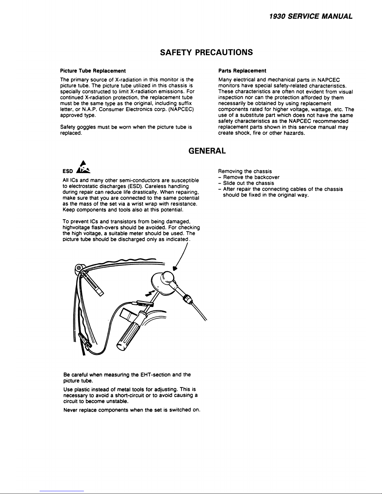
To prevent ICs and transistors from being damaged,
highvoltage flash-overs should be avoided. For checking
the high voltage, a suitable meter should be used. The
picture tube should be discharged only as indicated.
Removing the chassis
- Remove the backcover
- Slide out the chassis
- After repair the connecting cables of the chassis
should be fixed in the original way.
Be careful when measuring the EHT-section and the
picture tube.
Use plastic instead of metal tools for adjusting. This is
necessary to avoid a short-circuit or to avoid causing a
circuit to become unstable.
Never replace components when the set is switched on.
1930 SERVICE MANUAL
SPECIFICATIONS
(subject to modification)
AC voltage
- 120Vac + / - 10% - 60Hz
Power consumption at 120V
- 85 Watts
EHT
- 24 KV
Line frequency
- 31480 Hz
Frame frequency
- 60 Hz/70 Hz
Band width
- 18 MHz
Picture tu be (9C M08 2)
- M34 JPS 77 X 69
Picture tube (9C M 062)
- M34 JPM 70X69
RESOLUTION
Sync, polarity
HOR. VERT.
- pos/neg
Pos. Neg.
- 640 dots X 350 lines
Neg. Pos.
- 640 dots X 400 lines
Neg. Neg.
- 640 dots X 480 lines
INPUT SPECS
RGB linear - all colors
Sync TTL level - pos/neg
CONTROLS
Front : Power on/off SK1 (incl. LED indicator)
: Brightness (R558)
: Contrast (R322)
: Horizontal phase (centering) (R408)
: Vertical centering (R524)
Rear : Horizontal width (R541)
: Vertical height (R513 for 480 lines)
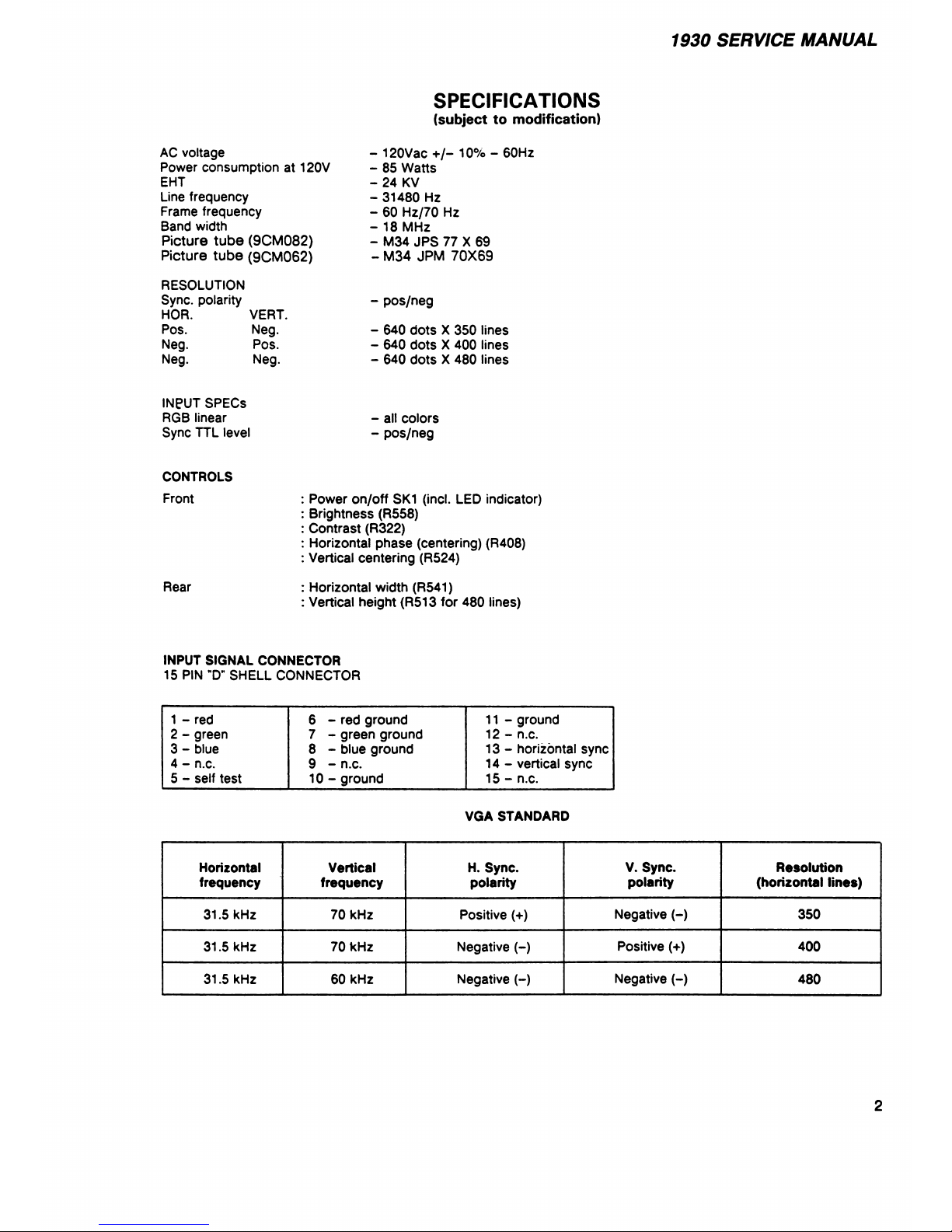
INPUT SIGNAL CONNECTOR
15 PIN ”D” SHELL CONNECTOR
1 - red
6 - red ground
11 - ground
2 - green
7 - green ground
12 - n.c.
3 - blue
8 - blue ground
13 - horizontal sync
4 - n.c.
9 - n.c. 14 - vertical sync
5 - self test
10 - ground 15 - n.c.
VGA STANDARD
Horizontal
Vertical H. Sync.
V. Sync. Resolution
frequency
frequency
polarity
polarity (horizontal lines)
31.5 kHz 70 kHz
Positive (+)
Negative (-) 350
31.5 kHz 70 kHz
Negative (-)
Positive (+)
400
31.5 kHz 60 kHz Negative H
Negative (-)
480
2
1930 SERVICE MANUAL
MECHANICAL/ELECTRICAL PARTS
Ref. Description
Pert No.
Front Cabinet
1492150171
Rear Cabinet 149216 0058
Push Button O n/O ff 149 4200366
Cover for Controls 149132 0305
Pad (Table Protectors)
44952000 03
Lock for Cove r 1491410003
Adjust Rod
1191000039
Slider Chassis
149303 0033
Pedestal
1491080019
Holder Line Input Transformer
149107 0126
S Mains Cord
4692 0200 69
S Picture Tube (9 CM 082)
M34JP S77X69
S Picture Tube (9C M062 )
M34JPM 70X 69
Custom er Inst. Book (9CM 082)
IB53790001
Custom er Inst. Book (9CM 062)
IB55180001
Foot Pedestal (9C M082)
1491080019
Foot Pedestal (9C M062)
1491030024
Degaussing Coil
36913000 12
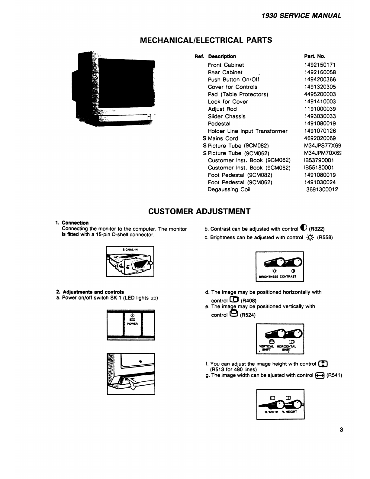
CUSTOMER ADJUSTMENT
1. Connection
Connecting the monitor to the computer. The monitor
is fitted with a 15-pin D-shell connector.
SIGNAL4N
2. Adjustments and controls
a. Power on/off switch SK 1 (LED lights up)
0
POWER
b. Contrast can be adjusted with control € (R322)
c. Brightness can be adjusted with control -j6/ (R558)
O
BRIGHTNESS CONTRAST
d. The image may be positioned horizontally with
control CD (R408)
e. The image may be positioned vertically with
control ( 3 (R524)
© CD
VERTICAL HORIZONTAL
, SHIFT SHIRT
f. You can adjust the image height with control CD
(R513 for 480 lines)
g. The image width can be ajusted with control
e
(R541)
b m
H. WIDTH V. HEIGHT
3
1930 SERVICE MANUAL
©
' © " 0 9
CD
4
1930 SERVICE MANUAL
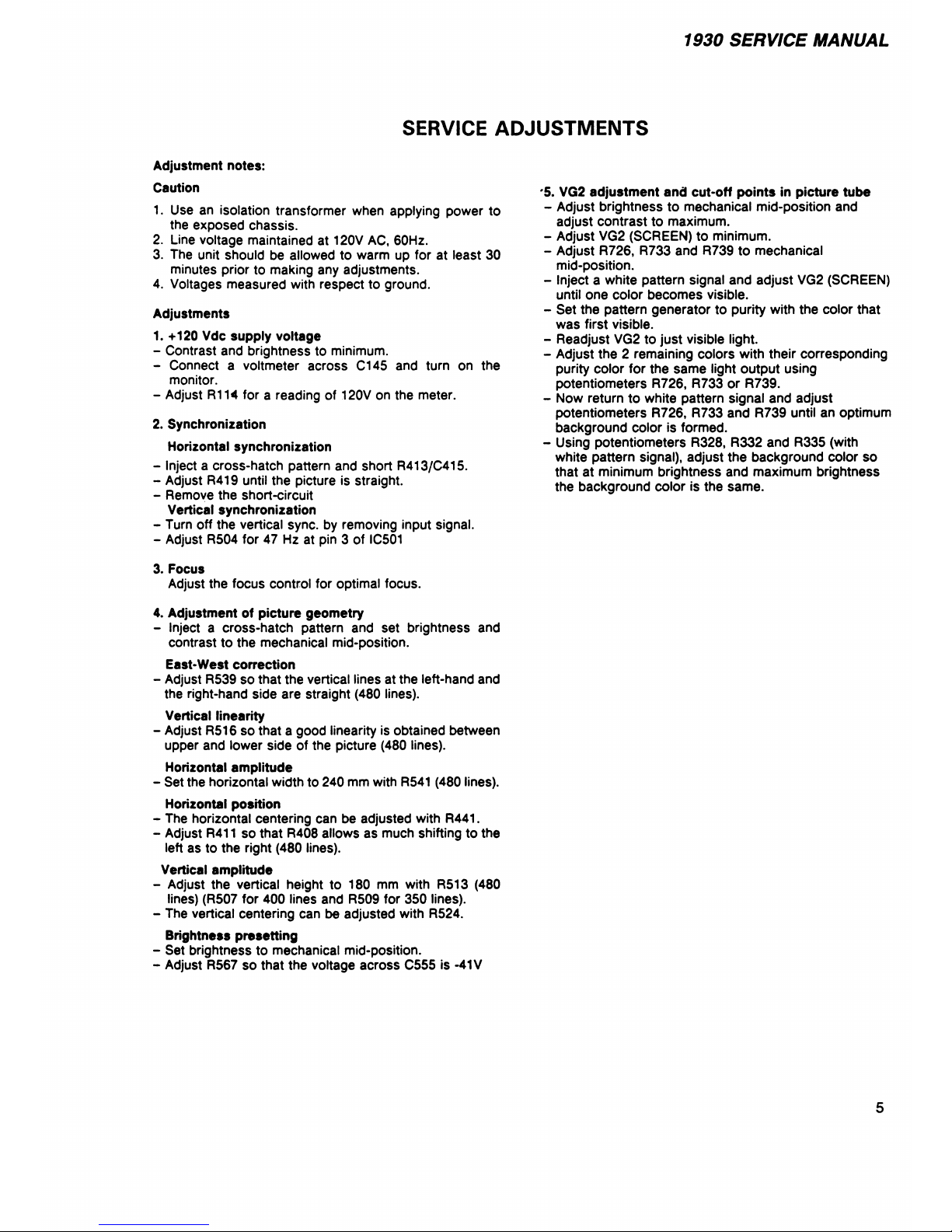
SERVICE ADJUSTMENTS
Adjustment notes:
Caution
1. Use an isolation transformer when applying power to
the exposed chassis.
2. Line voltage maintained at 120V AC, 60Hz.
3. The unit should be allowed to warm up for at least 30
minutes prior to making any adjustments.
4. Voltages measured with respect to ground.
Adjustments
1. +120 Vdc supply voltage
- Contrast and brightness to minimum.
- Connect a voltmeter across C145 and turn on the
monitor.
- Adjust R114 for a reading of 120V on the meter.
2. Synchronization
Horizontal synchronization
- Inject a cross-hatch pattern and short R413/C415.
- Adjust R419 until the picture is straight.
- Remove the short-circuit
Vertical synchronization
- Turn off the vertical sync, by removing input signal.
- Adjust R504 for 47 Hz at pin 3 of IC501
3. Focus
Adjust the focus control for optimal focus.
4. Adjustment of picture geometry
- Inject a cross-hatch pattern and set brightness and
contrast to the mechanical mid-position.
East-West correction
- Adjust R539 so that the vertical lines at the left-hand and
the right-hand side are straight (480 lines).
Vertical linearity
- Adjust R516 so that a good linearity is obtained between
upper and lower side of the picture (480 lines).
Horizontal amplitude
- Set the horizontal width to 240 mm with R541 (480 lines).
Horizontal position
- The horizontal centering can be adjusted with R441.
- Adjust R411 so that R408 allows as much shifting to the
left as to the right (480 lines).
Vertical amplitude
- Adjust the vertical height to 180 mm with R513 (480
lines) (R507 for 400 lines and R509 for 350 lines).
- The vertical centering can be adjusted with R524.
Brightness presetting
- Set brightness to mechanical mid-position.
- Adjust R567 so that the voltage across C555 is -41V
#5. VG2 adjustment and cut-off points in picture tube
• Adjust brightness to mechanical mid-position and
adjust contrast to maximum.
- Adjust VG2 (SCREEN) to minimum.
- Adjust R726, R733 and R739 to mechanical
mid-position.
- Inject a white pattern signal and adjust VG2 (SCREEN)
until one color becomes visible.
- Set the pattern generator to purity with the color that
was first visible.
- Readjust VG2 to just visible light.
- Adjust the 2 remaining colors with their corresponding
purity color for the same light output using
potentiometers R726, R733 or R739.
- Now return to white pattern signal and adjust
potentiometers R726, R733 and R739 until an optimum
background color is formed.
- Using potentiometers R328, R332 and R335 (with
white pattern signal), adjust the background color so
that at minimum brightness and maximum brightness
the background color is the same.
5
 Loading...