

Commodore 1701, 1702 Service Manual
SERVICE
MANUAL
MODEL
1701/1702
MONITOR
Preliminary
OCT.
1984
PN-314004-01
Commodore Business Machines, Inc.
1200
Wilson Drive,
West
Chester, Pennsylvania
19380
U.S.A.
Commodore makes no expressed
or
implied
war-
ranties
with
regard
to
the
information
contained
herein. The information is made available solely on
an as is basis, and
the
entire risk as
to
quality
and
accuracy is
with
the
user. Commodore shall
not
be
liable
for
any consequential or incidental damages
in connection
with
the
use
of
the
information
con-
tained herein. The listing
of
any available replace-
ment
part herein does
not
constitute
in
any
case
a recommendation,
warranty
or
guaranty
as
to
quality
or
suitability
of
such replacement part.
Reproduction or use
without
expressed permission,
of
editorial
or
pictorial
content,
in any
matter
is
prohibited.
This manual contains copyrighted and proprietary
information.
No part
of
this
publication may
be
reproduced, stored in a retrieval
system,
or
transmitted
in any
form
or
by
any
means, electronic, mechanical,
photocopying, recording or otherwise,
without
the
prior
written
permis-
sion
of
Commodore Electronics Limited.
Copyright © 1984
by
Commodore Electronics Limited.
All
rights reserved.

CONTENTS
Title
Page
SPECIFICATIONS
1
SAFETY PRECAUTIONS
.........................................................................................
2
ADJUSTMENTS
PURITY
......................................................................................................
4
CONVERGENCE
...........................................................................................
5
WHITE BALANCE
........................................................................................
5
B1
VOLTAGE, FOCUS, VERT. & HOR. ADJ.
...................................................
6
SUB TINT, SUB CONTRAST, COLOR SYNC,
3.58
MHz TRAP
...........................
7
BLOCK DIAGRAM
.................................................................................................
8
CIRCUIT NOTES
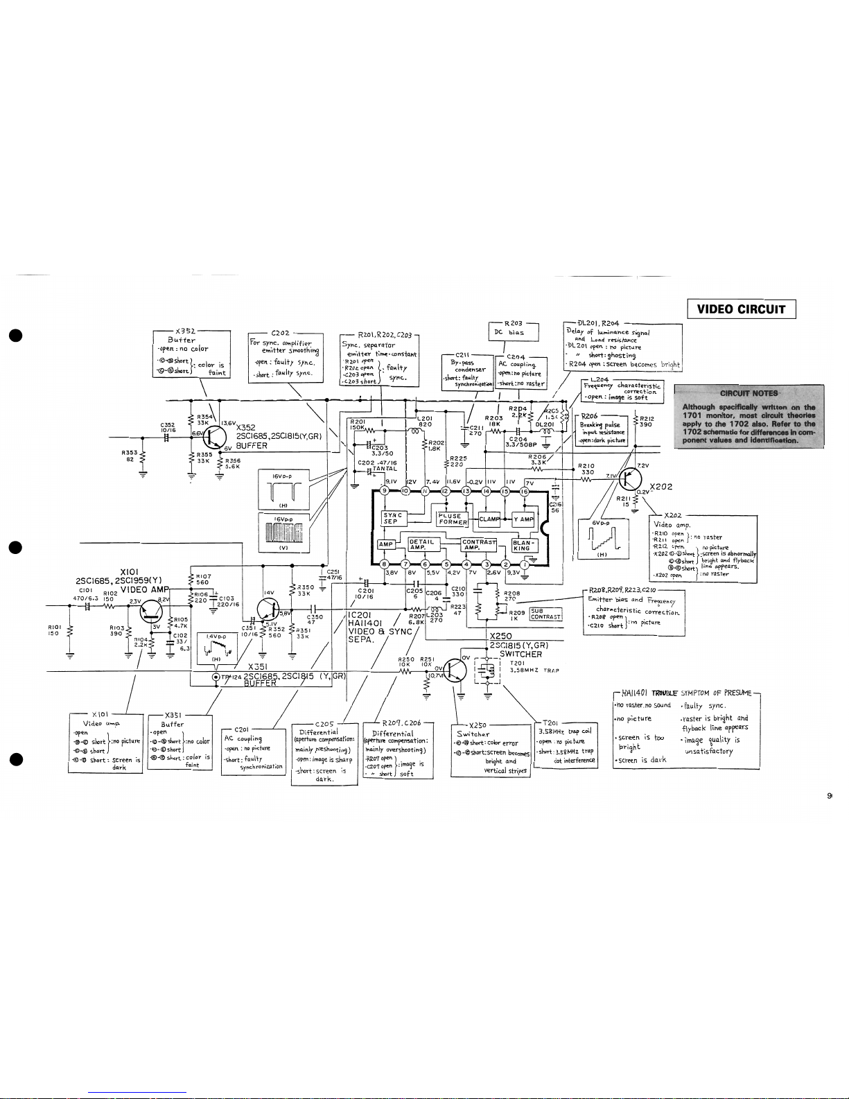
VIDEO CIRCUIT
...........................................................................................
9
AUDIO CIRCUIT
..........................................................................................
10
COLOR DEMODULATION CIRCUIT
................................................................
11
CHROMA OUTPUT CIRCUIT
............
..........................
..............
........
.............
12
CONTROL CIRCUIT
......................................................................................
13
H.
OSC., V. OSC. & V. OUT CIRCUIT
............................................................
14
HORIZONTAL OUTPUT CIRCUIT
...................................................................
15
POWER
CIRCUIT
.........................................................................................
16
TROUBLESHOOTING GUIDE
NO
RASTER,
NO
SOUND
(B
1
NORMAL)
........................................................
17
NO
RASTER,
NO
SOUND
(B1
ABNORMAL)
....................................
................
18
NO
RASTER, NORMAL SOUND
.....................................................................
19
NO
SOUND, NORMAL PICTURE
....................................................................
19
SINGLE HORIZONTAL LINE, NORMAL SOUND
................................................
20
IMPROPER
HORIZONTAL
OR
VERTICAL SYNC
...............................................
22
iii
CONTENTS
(Continued)
Title
Page
1701 PARTS LIST
..
...............................................................................................
23
1701 BOARD
LAyOUT.........
.................................................................................
30
1701 SCHEMATIC NOTES
.....................................................................................
31
1701 SCHEMATIC
................................................................................................
31
1702
MODEL IDENTIFICATION
........................................
........................
...............
32
1702
PARTS LIST
.................................................................................................
33
1702
BOARD LAYOUT
..........................................................................................
40
1702
SCHEMATIC NOTES
.....................................................................................
41
1702
SCHEMATIC
...........................................
.....
................................................
41
1702T
BOARD LAYOUT
........................................................................................
42
1702T
UNIQUE PARTS
..........................................................................................
43
1702T
SCHEMATIC
..............................................................................................
43
iv
GENERAL DESCRIPTION
C1701/C1702
COLOR
MONITORS
PRODUCT
SPECIFICATION
The C1701 and
C1702
are quality, high resolution color monitors, designed
to
maximize
the
video
capabilities
of
your
Commodore Computer. They give you a superior color picture
that
enhances
your
computing
experience and are completely compatible
with
all Commodore equipment.
SCREEN SIZE
13
Inch (screen measured diagonally). NTSC color standard
DISPLAY
40
Columns x
25
lines
RESOLUTION
1000
Characters per screen
CONTROLS
Color,
tint,
brightness, contrast, volume, vertical hold and horizontal hold
AUDIO
Built-in audio amplifier and speaker
INPUTS
Chrominance, luminance, composite video and audio
OTHER FEATURES
Video cassette recorder compatible
(1
V p-p,
75
Ohms)
COMPUTERS
Commodore
64,
VIC
20,
Plus/4 and
C16
POWER REQUIREMENTS
120
Volts,
60
Hz,
0.85
Amps
POWER CONSUMPTION
87
Watts
All specifications subject
to
change
without
notice.
1
SAFETY
PRECAUTIONS
1. This
product
contains special designed circuits and
components
that
were designed
for
safety
purposes.
For continued
protection,
changes should
not
be made
to
the
original design unless authorized
in
writing
by
the
manufacturer. Replacement parts
must
be identical
to
those used in
the
original
circuits. Service should
be
performed
by
qualified personnel only.
2. Alterations
to
the
design or
circuitry
of
this
receiver should
not
be made.
Any
design alterations
or
additions
will
void
the
manufactuer's
warranty
and
will
further
relieve the
manufacturer
of
responsibility
for
personal injury or
property
damage resulting
therefrom.
3.
Many
electrical and mechanical parts in MONITOR sets have special safety-related characteristics.
These characteristics are
often
not
evident
from
visual inspection nor can the protection afforded
by
them
necessarily
be
obtained
by
using replacement components rated for higher voltage,
watt-
age, etc. Replacement parts
which
have these special
safety
characteristics are identified in
the
parts list
of
this
service manual. Electrical
components
having such features are identified
by
shading on the schematics and by
(*)
on the parts list in this service manual. The use
of
a substitute
replacement
which
does
not
have
the
same
safety
characteristics
as
the
recommended
replacement part
shown
in
the
parts list
may
create shock, fire,
or
other
hazards.
4.
If
any repair has been made
to
the chassis,
it
is recommended the
the
B1
setting
be checked
or adjusted (See ADJUSTMENT
OF
B1
VOLTAGE).
5. The high voltage applied
to
the picture tube must conform
with
that
specified in this service manual.
Excessive high voltage can cause an increase in X-Ray emission, arcing and possible
component
damage, therefore operation under excessive high voltage conditions should
be
kept
to
a minimum,
or should
be
prevented.
If
severe arcing occurs, remove
the
AC
power
immediately and deter-
mine
the
cause by visual inspection (incorrect installation, cracked or melted high voltage harness,
poor soldering, etc.).
To
maintain
the
proper
minimum
level
of
soft
X-Ray emission,
components
in
the
high voltage
circuitry
including
the
picture
tube,
must
be
the
exact
replacements
or
alter-
natives approved
by
the
manufacturer
of
the
complete product.
6. Do
not
check high voltage by
drawing
an arc. Use a high voltage meter
or
a high voltage probe
with a VTVM.
Discharge
the
picture
tube
before
attempting
meter connection
by
connecting a
clip lead
to
the ground frame and connecting the other end
of
the lead through a 1
OkO
2W
resistor
to
the
anode
button.
7. When service is required, observe
the
original lead dress. Extra precaution should be given
to
assure
correct
lead dress in
the
high voltage
circuit
area. Where a
short
circuit
has occurred,
those components
that
indicate evidence
of
overheating should be replaced.
Always
use the
manufacturer's
replacement components.
2
SAFETY
PRECAUTIONS
(Continued)
8.
ISOLATION CHECK (SAFETY
FOR
ELECTRICAL SHOCK HAZARD)
After
re-assembling
the
product,
always
perfrom
an
isolation check on
the
exposed metal parts
of
the cabinet, screwheads, cable jacks, controls shafts, etc.,
to
be
sure
the
product
is safe
to
operate
without
danger
of
electrical shock.
(A)
DIELECTRIC STRENGTH TEST
The isolation between
the
AC primary
circuit
and all metal parts exposed
to
the
user, par-
ticularly any exposed metal part having a return path
to
the chassis should withstand a voltage
of
1,
100V
AC (r.m.s.)
for
a period
of
one second.
This method
of
test
requires
test
equipment
not
generally found in
the
service trade. *
(8)
LEAKAGE CURRENT CHECK
*
Plug
the
AC
line cord
directly
into
the
AC
outlet
(do
not
use a line isolation transformer dur-
ing
this
check). Using a
"Leakage
Current
Tester",
measure
the
leakage current
from
each
exposed metal part
of
the
cabinet, particularly any exposed metal part having a return path
to
the
chassis,
to a known
good earth ground (water pipe, etc.).
Any
leakage current
must
not
exceed
0.5mA.
ALTERNATE CHECK METHOD
Plug the AC line cord directly into
the
AC
output
(do
not
use a line isolation
transformer
during this check). Use
an
AC
voltmeter
having
1,000
ohms per
volt
or more
sensitivity
in
the
following
manner. Connect a
15000
10W
resistor paralleled by a 0.15JLF AC-type
capacitor between
an
exposed metal part and a
known
good earth ground (water pipe, etc.).
Measure
the
AC
voltage across the resistor
with
the
AC
voltmeter.
Move
the
resistor connection
to
each exposed metal part, particularly any exposed metal
part having a return path
to
the chassis, and measure
the
AC voltage across
the
resistor.
Now,
reverse the plug in the AC outlet and repeat each measurement.
Any
voltage measured
must
not
exceed
0.35V
AC (r.m.s). This corresponds
to
O.5mA AC (r.m.s.).
CAUTION:
When
troubleshooting,
with
power
applied, use an isolation
transformer
and
confirm
that
the
CRT
earth
wire
is
connected
to
the
CRT
socket
board
and
the
chassis.
3
ADJUSTMENTS
- PURITY, CONVERGENCE
AND
WHITE
BALANCE
PICTURE
TUBE
The picture tube is a precision in-line gun type. For this
picture tube, dynamic convergence is carried out by a precision deflection yoke which eliminates the use
of
a convergence yoke and a convergence circuit. The adjustment
of
the picture tube
is
therefore made easier
as
only the ad-
justment
of
static convergence by using a magnet is
enough. The deflection yoke and purity/convergency
magnets assembly
has
been
set at the factory and requires
no field adjustments.
However, should the assembly
be
accidentally jarred or
tampered vyith, some or all adjustment may
be
necessary.
COLOR
PURITY
& VERTICAL CENTER
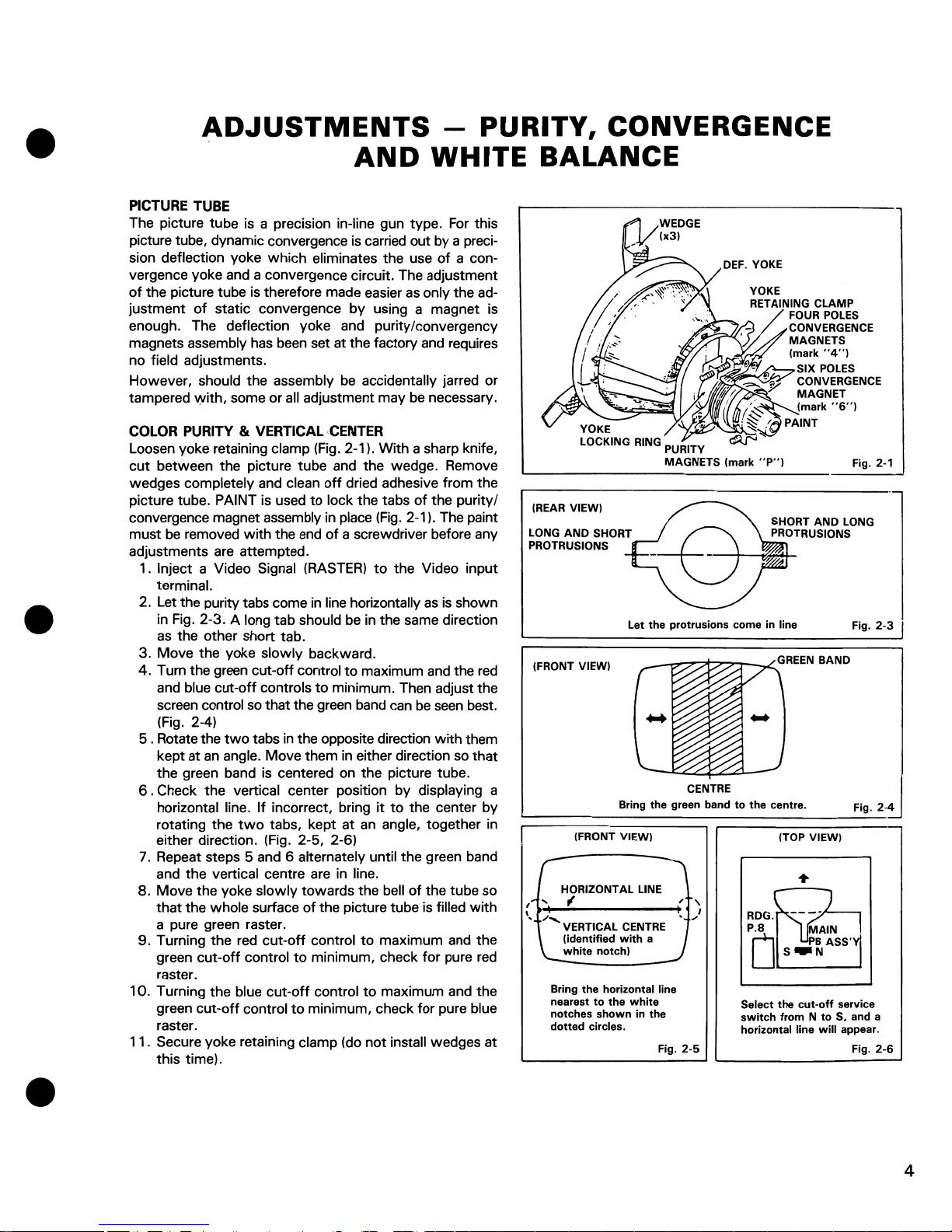
Loosen yoke retaining clamp
(Fig.
2-1). With a sharp knife,
cut
between the picture tube and the wedge. Remove
wedges completely and clean
off
dried adhesive from the
picture tube. PAINT is used
to
lock the tabs
of
the purity/
convergence magnet assembly in place
(Fig.
2-1). The paint
must
be
removed
with
the end
of
a screwdriver before any
adjustments
are
attempted.
1. Inject a Video Signal (RASTER)
to
the Video input
terminal.
2. Let the purity tabs come
in
line horizontally
as
is
shown
in Fig. 2-3. A long tab should
be
in the same direction
as
the other short tab.
3. Move the yoke slowly backward.
4. Tum the green cut-off control
to
maximum
and
the
red
and blue cut-off controls
to
minimum. Then adjust the
screen control
so
that the green band can
be
seen
best.
(Fig. 2-4)
5 . Rotate the
two
tabs
in
the opposite direction with them
kept at
an
angle. Move them in either direction
so
that
the green band is centered on the picture tube.
6 . Check the vertical center position by displaying a
horizontal line.
If
incorrect, bring it
to
the center by
rotating the
two
tabs, kept at
an
angle, together in
either direction. (Fig. 2-5, 2-6)
7. Repeat steps 5 and 6 alternately until the green band
and the vertical centre are
in
line.
a.
Move the yoke slowly towards the bell
of
the tube so
that
the whole surface of the picture tube is filled
with
a pure green raster.
9. Turning the red
cut-off
control
to
maximum and the
green cut-off control
to
minimum, check for pure
red
raster.
10. Turning the blue
cut-off
control
to
maximum and the
green cut-off control
to
minimum, check
for
pure blue
raster.
11.
Secure yoke retaining clamp (do
not
install wedges at
this time).
YOKE
LOCKING
RING
PURITY
MAGNETS (mark
"P")
Fig. 2-1
(REAR
VIEW)
LONG
AND
SHORT
PROTRUSIONS
Let
the
protrusions come in line
Fig.
2-3
(FRONT VIEW)
_--c..-;?""7f'7':7"T-..L
GREEN
BAND
CENTRE
Bring the green band
to
the
centre.
Fig.
2-4
(FRONT VIEW)
HORIZONTAL LINE
,~.....
f
'
..
/:.....
VERTICAL
CENTRE
(identified
with
a
'---
white
notch)
Bring
the
horizontal line
nearest
to
the
white
notches
shown
in
the
dotted
circles.
, ,
, I
."
Fig.
2-5
(TOP VIEW)
RDG
.
l~J,--
___
--,
Select the
cut-off
service
switch
from N to
S. and a
horizontal line
will
appear.
Fig.
2-6
4
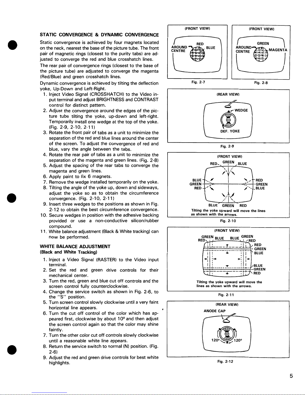
STATIC CONVERGENCE & DYNAMIC CONVERGENCE
Static convergence
is
achieved by four magnets located
on the neck, nearest the
base
of the picture tube. The front
pair
of
magnetic rings (closest
to
the purity tabs)
are
ad-
justed
to
converge the red and blue crosshatch lines.
The rear pair of convergence rings (closest
to
the base
of
the picture tube)
are
adjusted
to
converge the magenta
(Red/Blue) and green crosshatch lines.
Dynamic convergence
is
achieved
by
tilting the deflection
yoke, Up-Down and Left-Right.
1. Inject Video Signal (CROSSHATCH)
to
the Video in-
put terminal and adjust
BRIGHTNESS
and CONTRAST
control for distinct pattern.
2. Adjust the convergence around the edges
of
the picture tube tilting the yoke, up-down and left-right.
Temporarily install one wedge
at
the top
of
the yoke.
(Fig.
2-9, 2-10, 2-11)
3. Rotate the front pair
of
tabs
as
a unit
to
minimize the
separation
of
the red and blue lines around the center
of
the screen. To adjust the convergence
of
red
and
blue, vary the angle between the tabs.
4.
Rotate the rear pair
of
tabs
as
a unit
to
minimize the
separation
of
the magenta and green lines. (Fig. 2-8)
5. Adjust the spacing
of
the rear tabs
to
converge the
magenta and green lines.
6. Apply paint
to
fix 6 magnets.
7. Remove the wedge installed temporarily
on
the yoke.
8. Tilting the angle
of
the yoke up,
down
and sideways,
adjust the yoke so
as
to
obtain the circumference
convergence. (Fig. 2-10, 2-11)
9. Insert three wedges
to
the positions
as
shown
in
Fig.
2-12
to
obtain the best circumference convergence.
10. Secure wedges
in
position
with
the adhesive backing
provided or use a non-conductive silicon/rubber
compound.
11. White balance adjustment (Black & White tracking) can
now
be
performed.
WHITE BALANCE ADJUSTMENT
(Black and White Tracking)
1. Inject a Video Signal
(RASTER)
to
the Video input
terminal.
2. Set the
red
and green drive controls for their
mechanical center.
3. Turn the red, green and blue
cut
off
controls and the
screen control fully counterclockwise.
4.
Change the service
switch
as
shown
in Fig. 2-6,
to
the
"S"
position.
5. Turn screen control slowly clockwise until a very faint
horizontal line appears.
6. Turn the cut
off
control
of
the color which has appeared first, clockwise by about 10° and then adjust
the screen control again
so
that
the color may shine
faintly.
7. Turn the other color cut
off
controls slowly clockwise
until a reasonable white line appears.
8. Return the service switch
to
normal
(N)
position. (Fig.
2-6)
9. Adjust the red and green drive controls for best
white
highlights.
(FRONT VIEW)
(FRONT VIEW)
RED
AROUND
l)
BLUE
r
GREEN
\
AROUND~
CENTRE
~
MAGENTA
CENTRE
.'
. ' ,
Fig.
2-7
Fig.
2-8
(REAR VIEW)
(l)WEDGE
DEF.
YOKE
Fig.
2-9
(FRONT VIEW)
BLUE
r
;\1.<
BLUE
-_."
I
""
RED
GREEN-~,,~'----~I~--~:~_'~-GREEN
RED -,."
,;'--
_BLUE
>+~,
BLUE
GREEN
RED
Tilting
the
yoke
upward
will
move
the lines
as
shown
with
the
arrows.
Fig.
2-10
(FRONT VIEW)
Tilting
the yoke
upward
will
move
the
lines
as
shown
with
the
arrows.
Fig. 2-11
(REAR VIEW)
ANODE CAP
Fig.
2·12
5
NOTE:
1702
locations in (
).
81 VOLTAGE - Inject a video signal
1701
(110V)
Regulate VR, R109, for
B1
adjustment so
that
Dc voltage between TP-91 and earth is
110
volts.
1702
(125V.)
Confirm
that
the voltage at TP-94 and IC901 pin 4 is
125
volts.
NOTE:
Meter should
be
periodically calibrated at
20K
ohms/volt.
FOCUS
Adjust
the FOCUS control for best overall definition and picture detail at normal brightness and contrast.
VERTICAL POSITION
Adjust
the V. center
VR
R428 (R429)
to
the optimum vertical picture position.
VERTICAL HEIGHT
AND
LINEARITY
1. Display a pattern which allows easy confirmation
of
symmetry
(such
as
a circle or crosshatch).
2. Reduce the vertical size
with
the
V.
HEIGHT VR.
3. Adjust the vertical linearity
with
the V. LIN. VR.
4. Readjust the vertical height, so
that
the picture extends
to
normal size.
HORIZONTAL WIDTH
Adjust
H.
WIDTH control coil
L503
(L522) by turning it
with
a hexagonal adjusting bar only
if
RIGHT
and
LEFT
sides
of
picture
can't
be
seen.
HORIZONTAL OSCILLATOR
1. Set the
H.
FREQ.
VR
to
the mechanical center position.
2. Connect a jumper clip between TP-33A and TP-33B.
3. While rotating the
H.
FREQ.
VR, R504, keep the picture stationary or
slowly
moving.
4. Remove the jumper wire.
5. Make sure
that
the set maintains horizontal sync, when signals are switched.
6
SUB
TINT AND SUB
COLOR
1. Display a picture and set the
tint
and color VRs on the control panel
to
the central click position.
2. Adjust the sub
tint
VR, R305 and sub color VR, R303
for
the optimum display.
SUB
CONTRAST AND
SUB
BRIGHT
1 . Display a picture and set the contrast and bright VRs on the control panel
to
the center click positions.
2. Adjust
the
sub contrast VR, R209 and sub bright VR, R22 (R863)
for
optimum display.
COLOR SYNC
1 . Display a color video signal.
2. Connect jumper clips between TP-40 and earth
(TP-E)
and between TP-51 and IC301 pin 15
(TP-51
B).
3. Use a non-metallic screwdriver
to
turn trimmer capacitor
C308.
4. Adjust so
that
the rolling color stripes become
thick
and the rolling slows or stops.
5. Remove jumper clips.
6. Confirm
that
color sync is
not
disrupted when signals are switched.
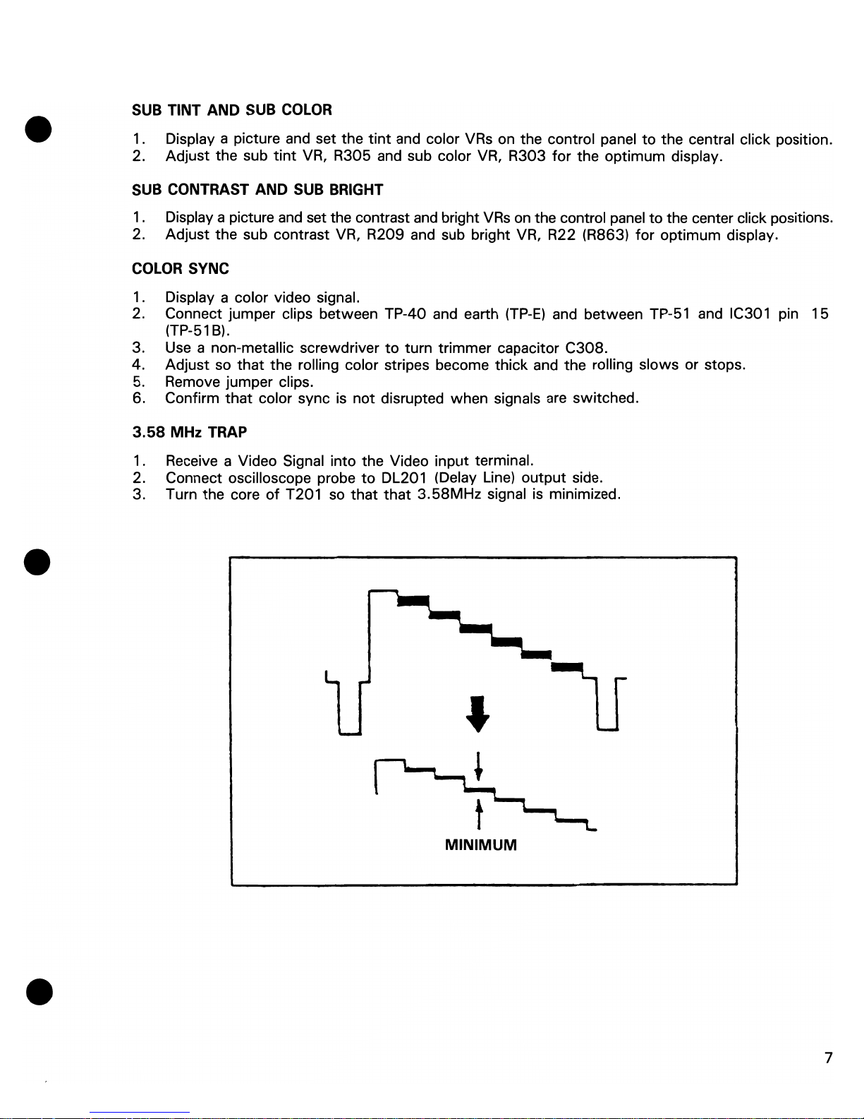
3.58
MHz TRAP
1 . Receive a Video Signal into the Video input terminal.
2. Connect oscilloscope probe
to
DL201 (Delay Line)
output
side.
3. Turn the core
of
T201 so
that
that
3.58MHz
signal is minimized.
MINIMUM
7
e
AUDIO
Y
(CHROMI-
NANCE)
C
(LUMI-
NANCE)
AUDIO VIDEO
L~
~J
r;:l
F
R
F
6
I
i-+81
0
,....
I
I
R
-0
-
..............
1
;J
SIGNAL
SELECT
S
R
0)
0
'-'
F
<"-~
"-
"
I
e
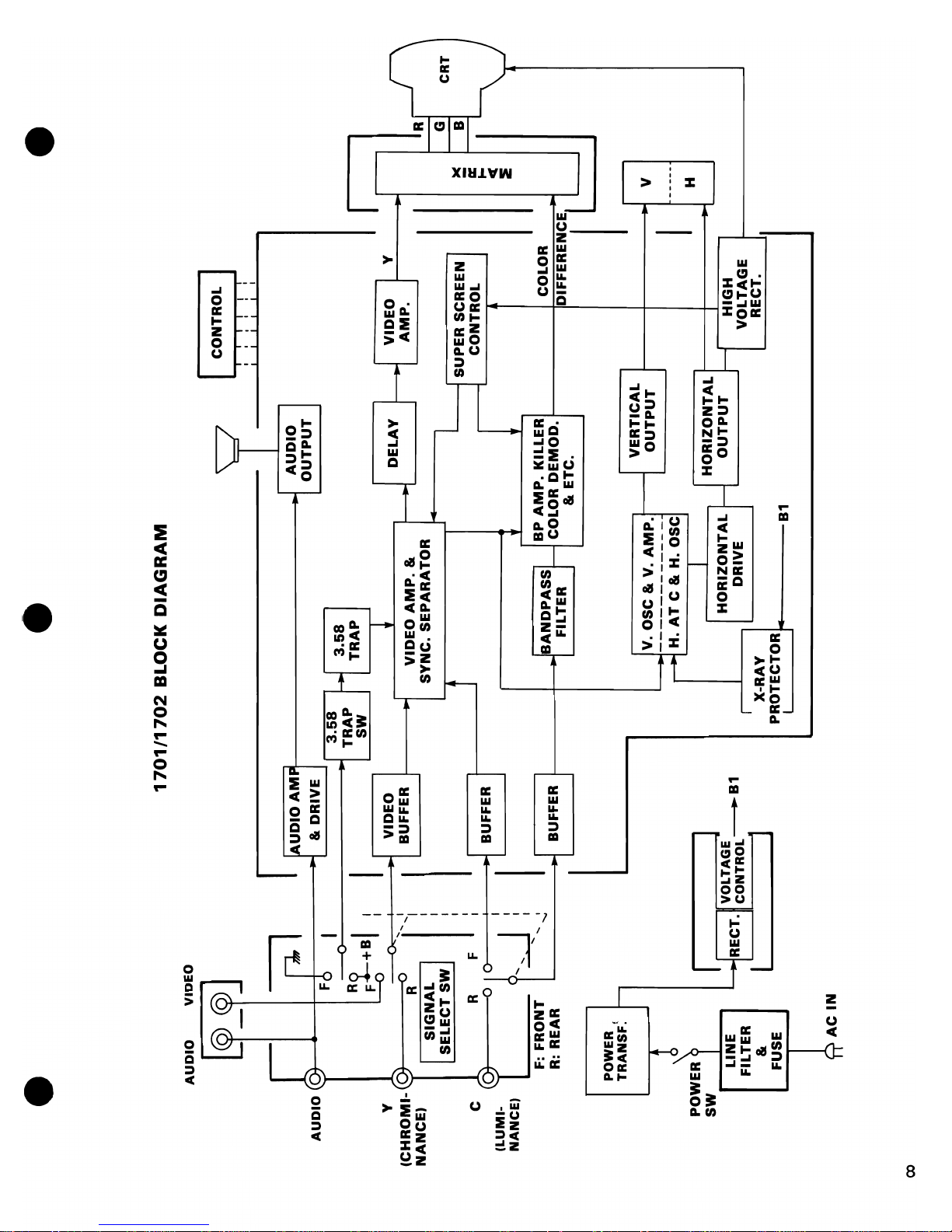
1701/1702
BLOCK
DIAGRAM
!AUDIO
AMP!
It
r-::UTPUT
&.
DRIVE
I I
3.58
f-"o
3.58
TRAP
SW
TRAP
~
DELAY
VIDEO
BUFFER
VIDEO
AMP.
&.
SYNC.
SEPARATOR
I
BUFFER
l
BP
AMP.
KILLER
I
CONTROL
I
iii
i I i
I I I I I I
I
VIDEO
I Y
AMP.
I
1
SUPER
SCREEN I
CONTROL
COLOR
e
fll.
r---c;
><
~
irE
r---
I-
C
::E
F:
FRONT
R:
REAR
BUFFER
JSANDPASS}-
FILTER
COLOR DE
MOD.
DIFFERENCE
1
'---
&.
ETC.
(X)
POWER
TRANSF:
LINE
FILTER
&.
FUSE
ACIN
I
.1
VOLTAGE
J
RECT. CONTROL
-B1
I i
VERTICAL
V. OSC
&.
V.
AMP.
I--
OUTPUT
~
------------
,.....
H.
AT
C
&.
H.
OSC
I
HORIZONTAL
HORIZONTAL
t--
OUTPUT
DRIVE
I
X-RAY
prOTECTOR
B1
roo--
V
I
--
---
H
'----
HIGH
VOLTAGE
I
RECT.
CRT
Rial
150
r---
)(
3
~2
----,
Buffer
-ope.n
;
no
color
:
eo
0""
is
.©~short}
I .
-@-®shart.
fuint
C202
-----,
For sync.
"",pli
fie
....
em
Itt~r
.5
)"nOoth
i~
-ope
It
~
fa.
u It)' sync.
- R2.oI,R202,C2o3
Sync. sera
n~tor
•
!?ZOZ.
cplU\
:
fa~lt)'
I
Dc,Rh~:~
I
C2 \ I
---'-""';
C2.o4
Br-~ss
Ac.
couplil1'}
condenser
-DL20I,
R204
t>e.lQ.y
of
!u.tooi/1C1.l"\ce
sitahGtI
~"ct
Lo(\ct
yesi~
tlU1C~
-t>l2o\
cp~n.
:
no
pktel
~
" snort:
~hostin~
-R204
0f~t\ ~ Sc~en
bq.col"neS~
~~9.
ht
I
VIDEO CIRCUIT
-$hort
: f""dtr
sr(\~·
~ln'I\"tc!'Y
t;~
-cansiaht
.
In"
\
Ope"
J
,C203
ope".
Sr
t1
c..
.c.2.o3c;hort
I
-J.
.&
It
'open:I"lO
picfClre
-snun.:
Ill"
r
synchTohitat;on
-ShoTt.
:1"10
Y/1s1e
r
L204
~-------~
F're<t."Eh?
chl1
yo.
¢teris
tic.
13.6V
X352
r--
R
-2-O-
1
---';"'--~-lL
201
ISOK
820
2SC16S5
,2SCISI5(Y,GR)
6V
BUFFER
R202
t.
aK
R353
82
XIOI
2SCI685,2SCI959(Y)
CIOI
RI02
VIDEO
AMP
470/6.3
150
RI03
390
RI04
2. 2K
- -
~/=
CI02
T
~331
6.3
-
16VP-p
(VI
14V
C351
'---1.4-V-P-'p--'
101
16
~U'
II
~
~
X351
I
C251
:=47/16
~
r--+--~--+---~
/
,IC20J
/
R207
L
203
/
HAI1401
6.aK
270
VI DEO a
SYNC
/
SEPAl
/
R250
R251
10K
10K
OV
'-
__
(e)
.....
_T_1¥12_4
.....
2'-""SCL.C.:.....16-""..S'-'-5_.
2_S_C......;I,--
8I5_{
Y--,'
IGR)
.l. / BUFFER / .
----
X\O\
--~-~
Vic!eo
amp.
·ope".
}
-®~
short
:"0
pic.tl4re
-@-@
short
-@
-e
S~ort:
Screen
is
dl1Tk
X351
---':""'"
Buffer
~;~:
shoTt
}:no
c.olor
·~-~short
-@~
shert
: color
is
faint
C20\
----'---,
f\.c.
co~pl;F\~
-open
:
110
pidl.(re
·short :
tal.\\
\ r
synchroniZPot;on
r-----
C 205"
-'---,
Differehti~1
(aperture
compensation:
'mllinly
preshooti
j'~)
·open
:
imo.~t
is
shu
rp
·short: screen ;,5
do.:rk.
Differentca.l
(aperture
CClnP'!n~tion:
lno.inly
overshcotin~)
.
~o'7
ope"
}
.<;2O'Topen
:
jma~e
is
-
"short
soft
/
T
C211
270
-
I
/'i:5_~
'2C]~
DL201
,.....A.,f\IIr+--tlI--+-J
I
R2r4
R203
2.
K
IBK
C
20
4
""T""...L
\/
3.3/50BP
-:::-
/,
COy~<:.t;ol"l.
-open. :
imo.,e
is
soft
R206
---,
S.,.Al\kir1
pu.lse
i"
"";;.
lesistQnce
-
open
:dark
piduR
CIRCUIT
NOTES
,
Although specifically written
on
the
170
1 monitor, most circuit theorlea
apply to the
1702
alao. Refer
to
the
1702
schematic for differences
In
c0m-
ponent values and IdentlflQatlon.
R206/
I
r-
__ ~ __ ~ ____
~3A·3~K
____
~~
R210
!
330
270
__
--
R209
SUS
'"I
I K
CONTRA~
I
X250
-
,.-
___ 2SCISI5 (Y,GR)
SWITCHER
T201
3.S8MH
Z
TRf
o?
6Vp.p
rvL
(HI
X202
--------------~
Vide.o
a,mo
.
I
-
R2.IO
Men
l
·R
2.1'
O~i'\
j : l"(Q ra.ster
"R2t2
c~"-
}
rIO
pldu.~
·x20Z
~:HI>skt:
:s...-reen
is
Ilbnortnally
~-0ShCft
hri'3
ht
I»"Id
flybaCk
@-®Short
t
line
Cll'pears_
•
X202
ODefl
: no YQS ter
I
R2.0~
.R2.0'/,
R223,c2/o
----,
Emitter
';)(as
and
freb'.H?hC;
.
chlll""cteristic
con-ec.
tiot\.
•
Rloe
OP"'h}
.
'C210
shOTt
:no
p,ctl\~
HA/l401
TROUBLE" SYMPTOM
DF
PRESIJME
...
X2~D
-----..,
Switche.r
·©-@short:color
error
'@
-@
short:
sc
reel'l
b~cctneS
briqht
and
vertical stripes
T201
-----.,
3.
SRMHt
tro..p
co\1
-Optm.
no
pic
tl4Te
-shoTt:
3.!;RMliz trap
dot
interference
-110
Tas.ter. no
Sound
.ho picture
-
sc.reen
is
too
Fn'i~h
t
•
SCree.n
is
dark
'multI
sync.
. raster is
brl~ht
Clhd
flyback line
ar~Qy".s
•
\ma~e
~ua.\;ty
is
un
sa.
tis
-Factory
I
9
"R65D,C651
1hp'4
to
'n!s~s
tClttce
unci
condehser
C6~2
,.--
"R(,!)!
,R6S2
Bias
l'eSisto.hCe.
·open: sound levei
becc
lY\es
h
i'jh
F
R6IS
-
~
n!Si~l1lnce
~
C6~D
Noise ab-;orb
·shot"t
:hO
SOUI\Q
I
-
I
.----
R607,
C60q
----,
N~t;ve
teed ha.ck 'resistClhce
(.612.
DC c.u.t cOhde.I'ISIt.'f"
.
open:
sound
level
becomes
hi~h
Boc~;,
conde.nser
~6DS',c608
Coupli~
TeSls~n~
and cOhdenser'
'F-bOS"
O~}
·c.oo&
open
:no
sound.
•
II
shari
.c?~n
:
no
souhd
ColO
---r
Couriil\l
cohd~sel'"
'opel"' :
no
')ound
T602 --......
Audio
ou~~-t
tT"(lhsf.
·open:
no
sound
"Rbi
1
------,
BillS
Y~stl1l\ce
·o~:
1"\0
Sl!l.Incl
1)601
---,
L.Ft
diode
·open: sound
!eve
I
becomes
low
R607
ISOK
\
C609
.015
200V
MY
-
C60S
.OI5MY
\C610
..--;---;-""Arr--;
i--+---+-----"W'r-i
. 4
7150
8 P
R617
470K
R615
47K..l.-
~606
.018MY
R603
~
68
~
~R61a
1"
iaOK
R6J2
~
2.2K
RG04
IK
\
IC601
HAIII07l
AUDIO
"R6D2,
R604
R608
220K
R609
6.8K
(V
X601-
R610
........
560
L7
~
"='"
-,
GC:-
4000A
--1
r
(M.\8 FR6011
(J
(00
I
112FRI
I
I
t +
l C613 .
14.711601
I
or
R61'T.
Rbl8
---,
Outfl4t
voH-C\~e
di"idih~
rec;istc~hce
.J
101l6~
fa
81 IIOV
,...---
c6ob~-
....
R603,C60S"
Filter
"Dc.
'Input
condense.r
CbI4.C6IS
-------"1
Noise
absorb
To,,~
~uQ.lj
ty
c.orrection
. short:
Y\.O
SCUtlQ
'R603
cpen
:no
sound
·R{,o2
open:sound
level
becomes
hi~.
VR
does
hot function.
'RbD4
(lpen:
sound
Ie.
vel
becomes
10
w.
. (;614
short:
soul'\d
level becomes
hiljh.
VR
does
hot
fundio/\.
.c
bll,;
~rt:
sound
ic.;
not
Cl",dible
unless
VR
is
"turned
at
least
ho.lf
way.
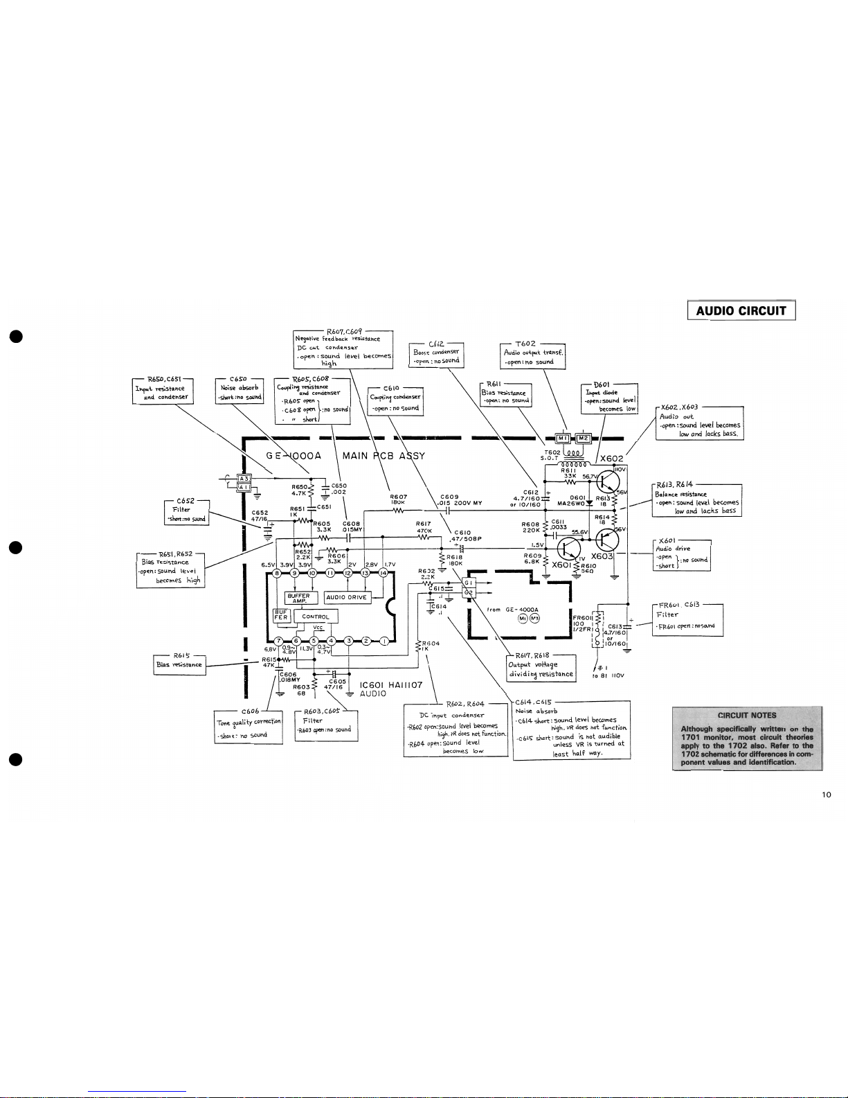
AUDIO CIRCUIT
XboZ
.X603
-------.,
Audio
out
·open:sound
level
becomes
low
and
lacks
bass.
R613.
R614
---~
BOola
t\c~
fesistllnc.e
• open: sound
leve.l
beComes
low
and
lacks
bass
;<601----.
AudIO
c!ri
ve
·open
~:
1\0 $Qohd
·short
1
FR601.
cbi3
---,
FilteY'
.
FF-(,o\
open:
noSouM
CIRCUIT NOTES
Although specifically written on the
1701
monitor, most circuit theories
apply to the
1702
also. Refer to the
1702
schematic for differences
in
com-
ponent values and identification.
10
•
1'10
piduye
T30i
---,
BP
take~off
transf.
,----
c302
Br-~~
conQenser
.open:
colD\"
beccmcs
$rk
'short;
no
color
R!oi---.,
Dumpi~
~is~nce
"open
:c%Y
error
4Vp-p
C303
N:.c
smoomlnj
•
open : no
~clor
R3,-3
Emmire~
~
...
-tGn~1e
-
C3
0
4-
Cou~in3
Cl)ndens~r
.open:
hD
coloy
"sheet:
no
picture.
c30S
--...,
K i
\l~
smocil\,'i
.
.:yw
"\:
ltO
~Ior
's~rt\
C304i:C305
180
-.45/50
R328
1M
R302.R303
Co\Oy
c:orrec.tloh
(bleeder
feS'StllllC~)
color
i~
'R3Dl
open:
faint
'R303
nDf!Tl:
color
is
·r _ ..
dink
R304,
R3DS,
R322
tl\'\t
c.orrectlon.
(bleeck.r
..-n\S~)
·R304
ore"':
Yec:\
ro.steY'
be.comes
lnDihel11'o...
'R:30!)
'f"'l
Hed
bf.CDtneS
"ftl,,,t.
~
beCCl'les
bi
...
e \:)ecomes vic,e.,-.
·R311. ~ :
titlt
VR
doeS
!\Of:
fu
nc-U
on
R.321
.-
____
AAr...rIK
___
_
+
10.7V C
316
z:::
10116
I
~
/
I
R316
22K
·only
tnDl1Ocln·omAtic.
·no ccioY,
edDY
-fad~
away
·no
monochroma.tic..
+.d-
IC301
HAII247
B.P
AMP,
ACC,KI
TINT,
APC,
VCO
a COLOR
OEM
I
.'
· fnultr
tint
"c.cicr
no;SE!
• cclor el'"rcr
.
faulty
color
sync.
. czlcr
beat
·dc.
..•
.----c306
Diff4e~n"ti4TeS,'5rnc.
si~
",,\,
a,"'cl
clela.ys
fho.o;e
of- pllise.
'OI'en : r-o"coloY
. short :
1'0
pIC
tttYl!.
dark
yaster
TP~5°1
I
~
0301:!:
I
S2473H
~5~6
C306
180
T
~
~
0302_.
ER,
1 S 2
47
3 H
,-c~r-.-:.::I
5::.:.1.:.55:,:5::.,
0303-0308
W06-A,W06-8,151555
R310
L351
330
~~-+----------~~.-~
or 1512473
22
0307 I R311
330
I
~----------~------.-~~-+-~
0306
I I R312 3301
G~53--~~~I~~~I--r-~I-~
R314
22
:.
~
•
J30g
2.2K
~
-:-
..!...
R322
~
10K
030'1,
R307.R30!i'-L.----.
For
phase
shOt
ft
C310,C311,C312
---,
'By"
p'l~'"
condl!nser
--
D
30
I
.---I.~-,
Foy
noise
prevention
.shon::
c:oloY'
errOl"
'C30'7
short
:5C~n
bec..::m'!s
bei'.1ht
\:I."t
ho
ccjOl"
'00'7
opt'll
}
obtain~
"R307
open
:no
color
"R301?
cpen
(ootp'lt
"IT;..
ba.se-~TCu.ncied
with
T6rect to
\U7'O\i"o."c:e
sl'y,a.I)
.
<:310
shan'
no
caree.n
Y'IsteY
.
C311
shcrt:
hO
red
ro.S
teY
·c312.
short:
no
bilAe.
ra.s!er
130 I. c 30&>,R3o'7,
c309 -
3.s8MH~
filhr
·'('3ot
o~n
,';hoT"t }
·c308
op~"
:tlO
colo
...
'R30'1
open
'C
3017
ope
...
,
sho~t
G3\3,C
314,
R3\3.
R~\4
APC
s",ooth~,,:}
'C313
Shod}
.c314
shOTt
:1\0 color
. R 3
i4-
open.
~-
L351,L31>2.
L3S3
t\
;,h
t"re:tu'!n"ff:
It
~Y"
·
L?S
\
opQ.n:
ydlcw
fictu.re
· L
~52
~
:cpM;c.rictLlI't.
· L 3
S"3
,,~"
:
m<l:1',enta
ftC.tun~
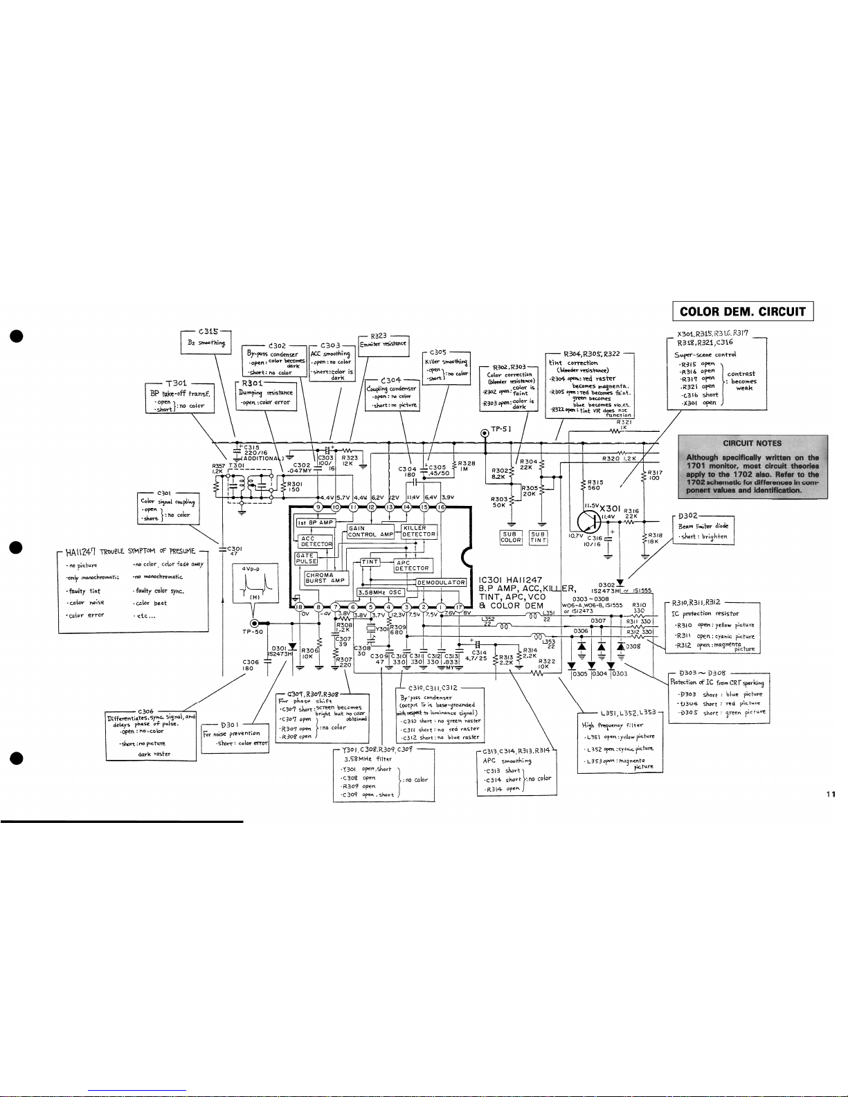
COLOR
DEM. CIRCUIT
"f..301.R315;1~3
1.6.
R3f'7
R3i'iLR321,C316
Su.~r-scene
ccnh-ol
'R~15
open.
"R
316
open
Got\t~st
'R31'T
oru'
becomes
.R32\
open weo.k
·(.31b
short
·xaot
open
CIRCUIT NOTES
Although speciflcally written on the
170
1 monitor, most circuit theories
apply
to
the
1702
also. Refer to the
1702
schematic
for
differences
In
com-
ponent values and Identification.
D302.---...,
Be"'" I:",iter
diode
. short :
br;~h+et1.
R310,R3i \,R3i2
----,
Ie
pl"t'tection reSistor
'R310
"pet:
yellow
i';ct
......
e
'R311
·R312.
cpen: cyanic p;cture
open. :
1Tla.'Jhent~
t
1
pIC
ure
D303
.......
D308
Roted,on.
of
Ie
frt,.,,,
CRT
SFrki"~
·E>303
short:
bllA4e
picture
"i)
304
short: · ....
ed
pIC
Tt.U'e
,-£)30 S
short:
~reet'\
fic
rure
1 1
 Loading...