

Commodore 1526, 4023, MPS 802 Service Manual

SERVICE
MANUAL
1526 • MPS
802 • 4023
PRINTERS
APRIL
1985
PN-314003-03
(
:::
C;C
.n1n10dore
COMPUTERS
SERVICE
MANUAL
1526
•
MPS
802
•
4023
PRINTERS
APRIL
1985
PN-314003-03
Commodore Business Machines, Inc.
1200
Wilson
Drive,
West
Chester,
Pennsylvania
19380
U.S.A.
Commodore makes no expressed or implied
war-
ranties
with
regard
to
the
information
contained
herein. The
information
is made available solely on
an as is basis, and
the
entire risk as
to
quality
and
accuracy is
with
the
user. Commodore shall
not
be
liable
for
any consequential
or
incidental damages
in
connection
with
the
use
of
the
information
con-
tained herein. The listing
of
any
available replace-
ment
part
herein does
not
constitute
in any case
a
recommendation,
warranty
or
guaranty
as
to
quality
or
suitability
of
such replacement part.
Reproduction or use
without
expressed permission,
of
editorial
or
pictorial
content,
in
any
matter
is
prohibited.
This manual
contains
copyrighted
and proprietary
information.
No
part
of
this
publication
may
be reproduced, stored in a retrieval
system,
or
transmitted
in any
form
or
by
any
means, electronic, mechanical,
photocopying, recording or otherwise,
without
the
prior
written
permis-
sion
of
Commodore
Electronics Limited.
Copyright © 1985
by
Commodore
Electronics Limited.
All
rights reserved.
CONTENTS
Title
Page
SPECIFICATIONS
SET
UP
AND TESTING
RIBBON CARTRIDGE
....................................................................................
2
PAPER
INSTALLATION
.................................................................................
3
SELF
TEST
.................................................................................................
4
ACCESSORIES PARTS LIST
............
.............................................
.....................
...... 5
MAINTENANCE
................
.............
....................
........................
..............
.......
.......
5
FUNCTIONAL BLOCK DIAGRAM
.........................
.................................
.....
..........
.... 6
CIRCUIT THEORY
POWER
SUPPLY
..........................................................................................
7
RESET
LOGIC
..
..........................
......................................
............................
8
CLOCK CIRCUIT
........................
......................................
............................
9
MICROPROCESSOR LOGIC
...............................................
............................
10
PAPER
FEED
MOTOR
.......
..........
..............
.................................
.....
..............
11
CARRIAGE MOTOR
..........
.......
.................
............................
.....
...................
12
PRINT WIRE DRIVE
......................................................................................
13
PRINT WIRE COIL PROTECTION
.........................................................
...... .....
14
PAPER
CONTROL LOGIC
.............................................................................
.
CARRIAGE POSITION AND HOME SENSOR
...................................................
.
15
16
1526
• MPS
802
INTERFACE LOGIC
...........................
.................................
17
4023
INTERFACE LOGIC
..........................
....................................................
18
TROUBLESHOOTING GUIDES
................................................
.................................
19
PCB
PARTS
LiST...................................................................................................
22
ROM UPGRADES ....
....................................
.......
...................
..............
..... ....... ... ....
24
1526
• MPS
802
SCHEMATIC
.......
....................
...................
.........
.....
............
.......
24
DEVICE NUMBER CHANGE ...... ... ....
....................
..........................
.......
..............
.....
25
4023
SCHEMATIC
................................................................................................
25
MECHANICAL ADJUSTMENTS
HEAD SHIFT
LEVER
.............................................
........................................
26
PRINT HEAD
...............................................................................................
26
HOME SENSOR
..........
............
.............................................
...................
..... 27
WIRING DIAGRAM
....................
...................
..............
.................................
...
.......
28
MECHANICAL DISASSEMBLY
.................................................................................
29
ASSEMBLY NOTES
................................................................................................
36
CASE WORK/POWER SUPPLY
................................................................................
37
MECHANICAL ASSEMBLIES
..
.................................................................................
38
SPECIFICA TIONS
•
1526
• MPS
802
•
4023
•
PRINT
METHOD
• Bi-directional impact
dot
matrix
CHARACTER
MATRIX
• 8 X 8 Dot Matrix
CHARACTERS • Upper & lower case letters
with
true descenders. Numerals &
symbols. All
PET
graphic characters
GRAPHICS
• 8 Vertical dots - maximum
640
columns
CHARACTER CODES • CBM ASCII code
PRINT
SPEED •
60
CPS
MAXIMUM
COLUMNS
•
80
Columns
LINE FEED
SPACING
• 6 Lines/inch in character mode
• 9 Lines/inch in graphics mode
LINE FEED SPEED • 5 Lines/sec in character mode
•
7.5
Lines/sec
in
graphics mode
PAPER FEED
•
Pin
feed
PAPER
WIDTH
•
4.5
to
10"
Width (including tractor feed holes)
•
8.5"
Width (after tractor holes)
MULTIPLE COPIES • Original plus maximum
of
3 copies
POWER REQUIREMENTS •
120
Volts AC,
60
Hz,
1.5
Amp
•
1526/MPS
802
•
•
4023
•
INTERFACE
COMPUTERS
• SERIAL
• VIC20, C64,
SX64, C16,
PLUS
4
INTERFACE
COMPUTERS
•
IEEE
Protocol
•
4032,
8032,
8096,
SP9000,
B-MODEL
1
SET
UP
AND
TESTING
VISUAL OBSERVATION is particularly important before attempting
to
repair a printer.
Always
check
for
physical damage
to
the
mechanism. Remove any loose debris
that
may
have
accumulated inside
the
unit.
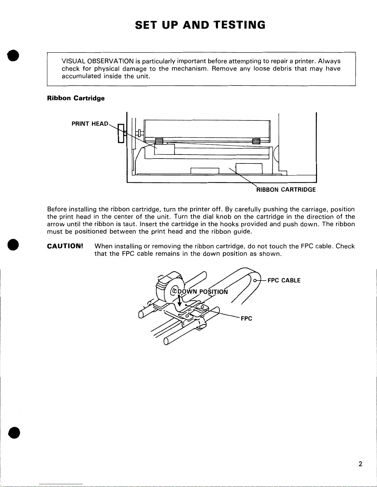
Ribbon
Cartridge
PRINT HEAD
RIBBON CARTRIDGE
Before installing
the
ribbon cartridge,
turn
the
printer
off.
By carefully pushing
the
carriage, position
the
print
head in
the
center
of
the
unit. Turn
the
dial knob on
the
cartridge in
the
direction
of
the
arrow
until
the
ribbon is
taut.
Insert
the
cartridge in
the
hooks provided and push
down.
The ribbon
must
be
positioned
between
the
print
head and
the
ribbon guide.
CAUTION!
When installing or removing
the
ribbon cartridge,
do
not
touch
the
FPC
cable. Check
that
the
FPC
cable remains in
the
down
position as
shown.
FPC
CABLE
2
SET
UP
AND
TESTING
(Continued)
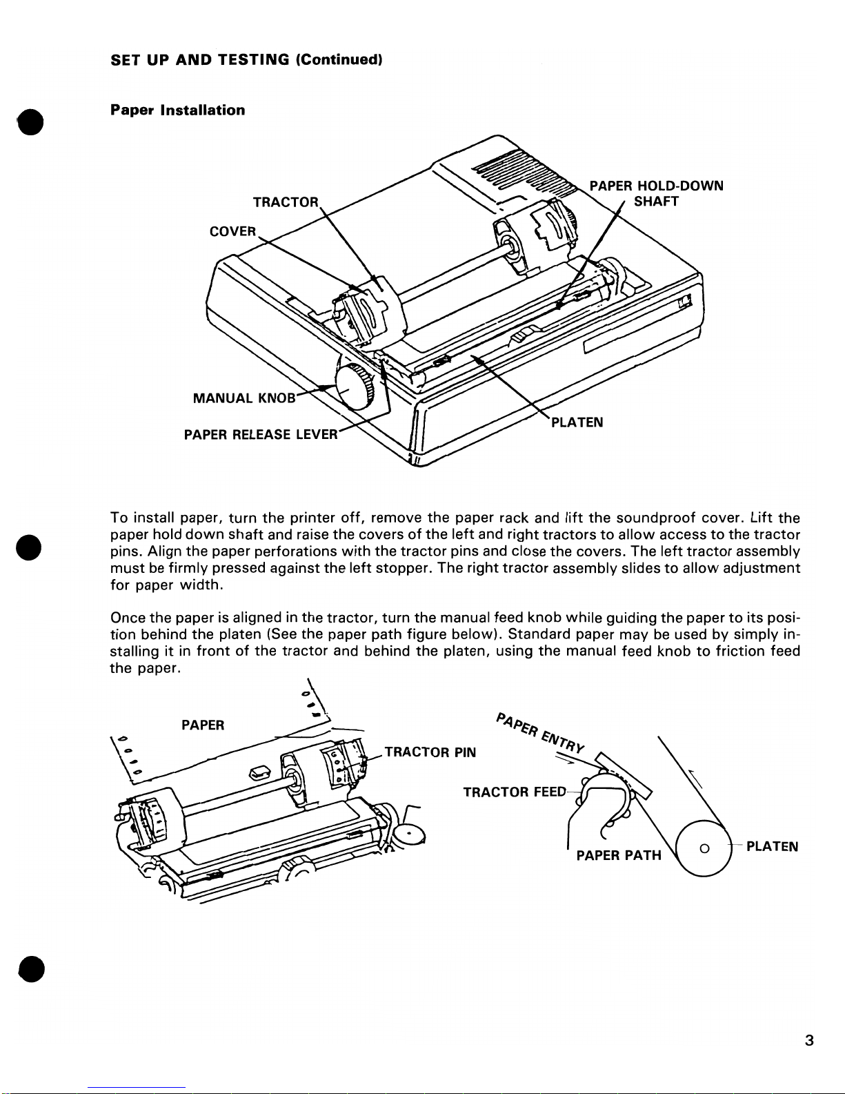
Paper Installation
PAPER RELEASE LEV
To install paper,
turn
the
printer
off,
remove
the
paper rack and
lift
the
soundproof
cover.
Lift
the
paper hold
down
shaft
and raise the covers
of
the
left
and
right
tractors
to
allow
access
to
the
tractor
pins. Align
the
paper perforations
with
the
tractor
pins and close the covers. The
left
tractor
assembly
must
be
firmly
pressed against
the
left
stopper. The right
tractor
assembly slides
to
allow
adjustment
for
paper
width.
Once
the
paper is aligned in
the
tractor,
turn
the
manual feed
knob
while
guiding
the
paper
to
its
posi-
tion
behind
the
platen (See
the
paper path figure below). Standard paper
may
be
used by
simply
in-
stalling
it
in
front
of
the
tractor
and behind
the
platen, using
the
manual feed knob
to
friction
feed
the
paper.
PAPER
TRACTOR PIN
TRACTOR
FEED
- PLATEN
3
SET
UP
AND
TESTING
(Continued)
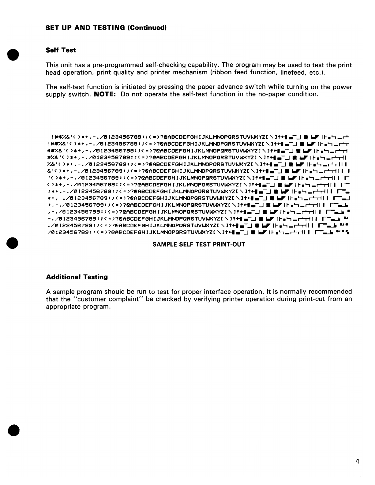
Self
Test
This
unit
has a pre-programmed self-checking capability. The program
may
be used
to
test
the
print
head operation,
print
quality
and
printer
mechanism (ribbon feed
function,
linefeed,
etc.).
The
self-test
function
is initiated
by
pressing
the
paper advance
switch
while
turning
on
the
power
supply
switch.
NOTE:
Do
not
operate
the
self-test
function
in
the
no-paper
condition.
!
H$"/.&
• ( ) * + , - •
/01234~6789
: ; <
:z
>?~ABCDEFGH
I
JKLI'r'NOPQRSTUVWXY2
[ " 11'+-11.-...1 •
.,
It-.
'-1
_
r'-
!
"$"/'&
• ( ) *
+.
- •
/01234~6789
I , <
..
>?@!ABCDEFGH I
JKLI'r'NOPQRSTUVWXY2
[ " 11'+-11.-...1 •
.,
It-.
'-1
_
~
"$%&
• ( ) * + , - •
/01234~6789
I ; <
..
)?~ABCDEFGH I JKL~PQRSTUVWXYl
[ "
11'+-1.-
...1 • .,
It- .'-1 _ r'-T-i
$"/.&
• (
).
+ ,
-.
/01234~6789:
,I
< =
>?~ABCDEFGH
I
JKLM'lOPQRSTUVWXYZ
[ "
If+-ll.
-...1 •
.,
It-.
'-1
_ r'-T-i I
X&·
( )
... , -.
/1211234:567891,
<
..
>?~ABCDEFGH
IJKL~PQRSTUVWXYzr"
11'+-11.-...1 •
.,
1t-.'-1
_r'-T-i
I I
eSc'
( ) * + , - • /EH
234567891
; < =
>?~ABCDEFGH
r
JKLMNJPQRSTUVWXYZ
[ " 11'+-1.-...1 •
.,
It-.
'-1
_ r'-T-i I I I
'(
) * + , - •
/0
123456789
I ; < =
)?@!ABCDEFGH r JKLMNOPQRSTUVWXYZ[
''If+-ll.
-...1 •
.,
It-.
'-1
_ r'-T-i I I r
( '* + , - •
/EH
23456789:
; < =
>?~ABCDEFGH
r
JKLMNJPGlRSTUVWXY2
[ " 11'+-11.-...1 •
.,
It-.
'-1
_ r'-T-i I I
r-
'* + , - •
/e'l123456789
I ; < c
>?~ABCDEFGH
r
JKLfw'NOPQRSTUVWXYl
[ " 1
l'
+-1
.-...1 • .,
It-.
'-1 _ r'-rll
I
r-_
* + ,
--
•
/121
1234~6789:
; < =
>?~ABCDEFGH
I
JKLfw'NOPQRSTUVWXYZ[
'-.11'+-1.-...1 •
.,
It-.
'-1 _ r'-rll
I
r--.J
t,
-.
/121123456789:
; < z
>'?~ABCDEFGH
I
JKLI'1'IOPQRSTUVWXYl
[
''If+-ll.-..J • .,
1t-.'-1
_r'-rll
I r---.J.
,
-.
/8123456789:
; < =
>?~ABCDEFGH
IJKLMNJPQRSTUVWXY2[
''\1
l'
+-1
.-...1 • .,
1t-.'-1
_r'-rll
I
r-
--.J.
•
-.
/121123456789
11 <
")?@!ABCDEFGH
rJKLMNOPQRSTUVWXYZ[
"]t+-I.-..J
•
.,
It-
.'-1_r'-rl1
I
r-
--.J.
...
•
/01234567891
) < :
>'?~ABCDEFGH
I
JKLMNOPGlRSTUVWXYl
[
''It+-ll
.-...1 • .,
1t-.'-1
_r'-rll
I r---.J.
...
.
/0123456789:
1<
'"
)?@!ABCDEFGHIJKLI'1'IOPGlRSTUVWXYl["
11'+-11.-...1 •
.,
1t-.'-1
_r'-rll
I
r-
--.J.
....
..
SAMPLE
SELF
TEST PRINT-OUT
Additional
Testing
A sample program should be run
to
test
for
proper
interface
operation.
It
is
normally
recommended
that
the
"customer
complaint"
be checked
by
verifying
printer
operation during
print-out
from
an
appropriate program.
4
Cleaning
ACCESSORIES
PARTS
LIST
C
314597-01
C314598-01
C
314598-02
C
314598-03
C
314599-01
C 1
51
5001 -01
C
903508-04
1526/802/4023
1526
MPS802
4023
1526/802/4023
1526/MPS802
1526/802/4023
MAINTENANCE
CAUTION
PAPER
RACK
USER'S
MANUAL
USER'S
MANUAL
USER'S
MANUAL
RIBBON
6PIN DIN CABLE
POWER CORD
Do
not
use chemicals
to
clean any
of
the
printer parts.
Using a clean,
dry
brush, remove
dust
and debris
from
the
ribbon guide, print head, platen area and
tractors
often.
Periodically remove
the
top
case and brush any accumulated
dust
or particles
from
the
unit.
Lubrication
CAUTION
Do
not
allow
oil or grease
to
contact
the
motors,
sensors,
tractors,
platen, ribbon
or
print head.
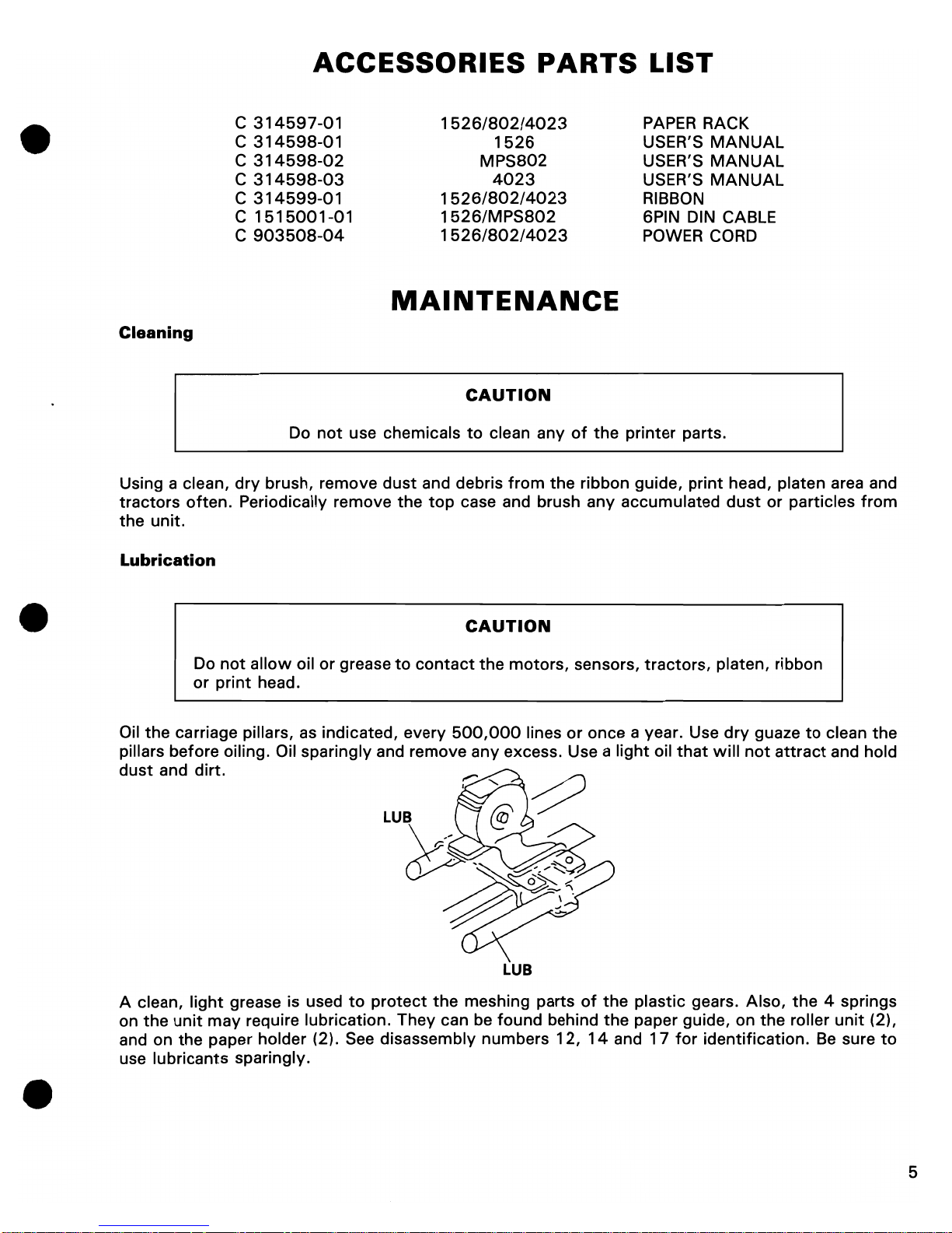
Oil
the
carriage pillars,
as
indicated, every
500,000
lines
or
once a year. Use
dry
guaze
to
clean the
pillars before oiling. Oil sparingly and remove any excess. Use a light oil
that
will
not
attract
and hold
dust
and dirt.
LUB
A clean,
light
grease is used
to
protect
the
meshing parts
of
the
plastic gears. Also,
the
4 springs
on
the
unit
may
require lubrication. They can be found behind
the
paper guide, on
the
roller
unit
(2),
and on
the
paper holder (2). See disassembly numbers
12,
14
and 1 7
for
identification.
Be
sure
to
use lubricants sparingly.
5
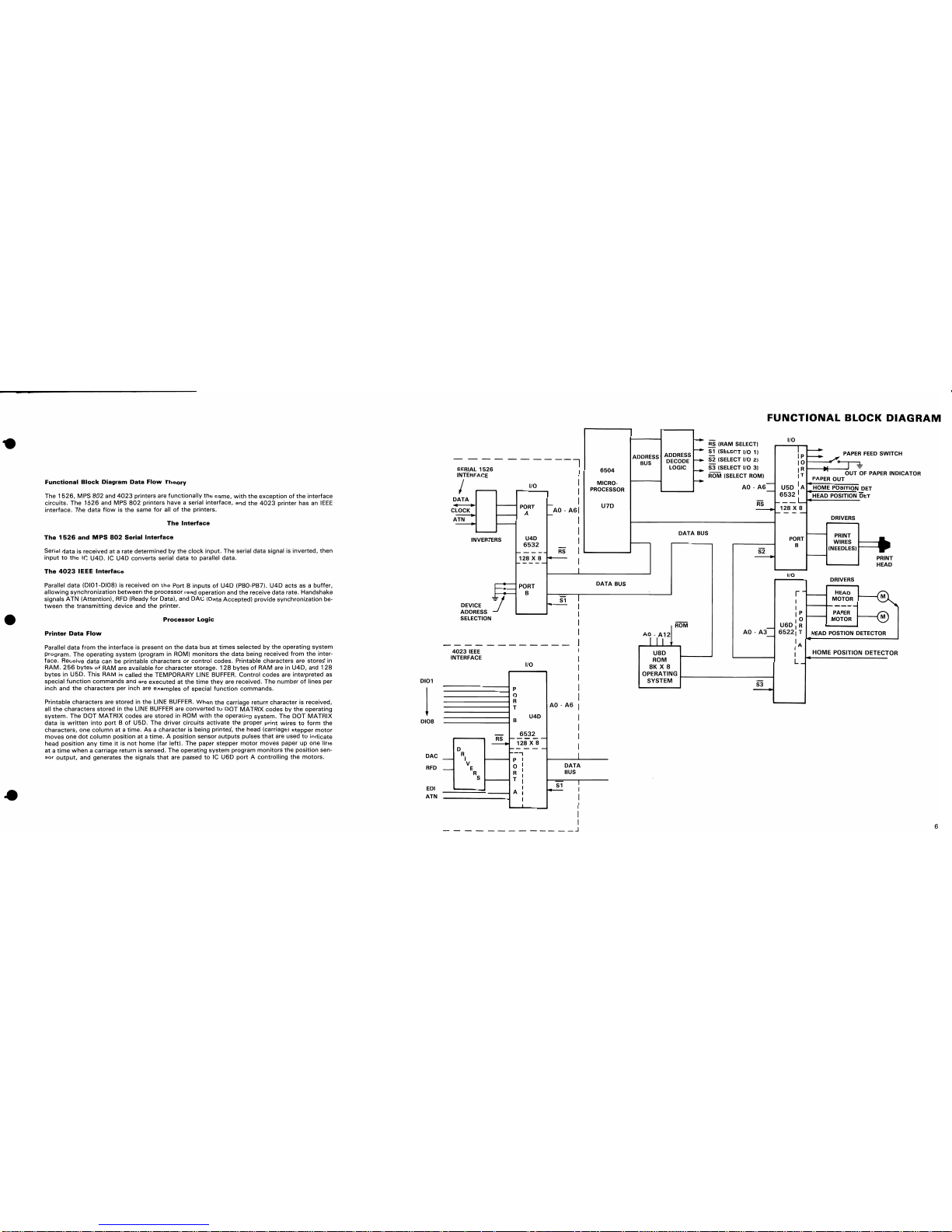
Functional
Block
Diagram
Data
Flow
Theory
The
1526,
MPS
802
and
4023
printers are
functionally
the
same,
with
the
exception
of
the
interface
circuits.
The
1526
and MPS
802
printers have a serial
interface,
and
the
4023
printer
has an
IEEE
interface.
The
data
flow
is
the
same
for
all
of
the
printers.
The
Interface
The
1526
and
MPS
802
Serial
Interface
Serial
data
is received at a rate determined
by
the
clock
input.
The serial
data
signal is
inverted,
then
input
to
the
IC
U4D.
IC
U4D
converts
serial data
to
parallel
data.
The
4023
IEEE
Interface
Parallel data (0101-DI08) is received on
the
Port B
inputs
of
U4D
(PBO-PB7).
U40
acts
as a buffer,
allowing
synchronization
between
the
processor
read
operation
and
the
receive data rate. Handshake
signals
ATN
(Attention),
RFD
(Ready
for
Oata), and DAC (Data
Accepted)
provide
synchronization
be-
tween
the
transmitting
device and
the
printer.
Processor
Logic
Printer
Data
Flow
Parallel
data
from
the
interface
is present
on
the
data bus
at
times
selected
by
the
operating
system
program.
The
operating
system
(program in ROM)
monitors
the
data
being received
from
the
inter-
face. Receive
data
can be printable
characters
or
control
codes. Printable
characters
are
stored
in
RAM.
256
bytes
of
RAM are available
for
character
storage.
128
bytes
of
RAM
are in
U40,
and
128
bytes
in
U5D.
This
RAM is called
the
TEMPORARY LINE BUFFER.
Control
codes are
interpreted
as
special
function
commands
and are
executed
at
the
time
they
are received. The
number
of
lines per
inch
and
the
characters per inch are
examples
of
special
function
commands.
Printable
characters
are stored in
the
LINE BUFFER.
When
the
carriage return
character
is received,
all
the
characters
stored in
the
LINE BUFFER are
converted
to
DOT
MATRIX
codes
by
the
operating
system.
The
OOT
MATRIX
codes are
stored
in ROM
with
the
operating
system.
The DOT
MATRIX
data
is
written
into
port B of
U50.
The
driver
circuits
activate
the
proper
print
wires
to
form
the
characters,
one
column
at a time.
As a character
is being
printed,
the
head (carriage)
stepper
motor
moves
one
dot
column
position
at a time. A position
sensor
outputs
pulses
that
are used
to
indicate
head
position
any
time
it
is
not
home (far
left).
The paper
stepper
motor
moves
paper
up
one line
at a time
when
a carriage return is sensed. The
operating
system
program
monitors
the
position
sen-
sor
output,
and generates
the
signals
that
are passed
to
IC
U60
port A controlling
the
motors.
0101
1
0108
DAC
RFD
EDI
ATN
SERIAL
1526
INTERFACE
I
----I
I
I
I
110
DATA
,~I
nr.K
~TN
t----I
PORT
A
INVERTERS
U4D
6532
DEVICE
ADDRESS
SELECTION
4023
IEEE
NTERFACE
----
128
X 8
1-----
r---~
PORT
1
-
B
I/O
--------------1
P
_______________
-1
0
----------------1 R
-----------------i T
---------------4
B
U4D
6532
RS
---
128
X 8
0
---
R
--,
I
P
I
V
0
1
E
R
R
I
S
T
I
I
I
A
f
I
- I
AD - A61
- I
RS
S1
AD -
A6
I
I
I
I
I
I
I
I
I
I
J
I
I
I
I
I
I
DATA
BUS
S1
I
I
I
I
I
__
J
6504
MICRO-
PROCESSOR
U7D
DATA
BUS
FUNCTIONAL
BLOCK
DIAGRAM
f---
RS
(RAM SelECT)
110
ADDRESS
BUS
ADDRESS
r--
-S1
(SELECT
110
1) I P
t::
DECODE
r--
S2 (SelECT
110
2) I 0
PAPER
FEED
SWITCH
LOGIC
r-- S3 (SelECT I/O 3)
II
~
t---.......--....I~UT
~F
PAPER
INDICATOR
ROM
(SELECT
ROM)
PAPER
OUT
r-- AD _
A6-
U5D
I
A~HUiOI~IME-;:;I':ru;ju:>llmllinul~IN
DET
'------I
-
6532
I :
HEAD
POSITION
DET
U8D
ROM
8K X 8
DATA
BUS
AD -
RS
---
--
OPERATING
t-------------I
SYSTEM
S3
___
L
128
X 8
1-----
PORT
B
I/O
r
-t----I
DRIVERS
PRINT
WIRES
(NEEDLES)
t---I
DRIVERS
HEAD
MOTOR
PRINT
HEAD
I
I
1----
....... ----
-
I P
1--_-1
1
0
PAPER
MOTOR
U6D
I R
65221T
HEAD
POSTION
DETECTOR
I A
.....
-----------'
I
I
L_
HOME POSITION DETECTOR
6

The
Power
Supply
CIRCUIT
THEORY
CR26
_::-::-::-:4
A:-'I/SO
V
or
1.S
AlSO
V
on
h.~t
sink
~-r:----r-:U)"""':::::
+5
V
N
I'"
",I
-.
uu
o"ai
L---~~~-+-~~-~---;uD
.
+.
RS
lO
k
C7
6800
SOV
+5V
GND
1--+_..::::::.+26
v
+26 V
GND
The
Power
Supply
generates
two
outputs,
+ 5VDC and +
26VDC.
Both
outputs
are regulated. The
5VDC
output
supplies
the
microprocessor and TTL circuits. The +
26VDC
output
supplies
the
print
wire
coils and
the
paper feed and carriage
motor
drive circuits.
+
5VDC
Supply
VR 1 is a series regulator. The series regulator keeps
the
output
voltage
constant
when
the
load varies.
Capacitive filtering eliminates
most
of
the
ripple voltage on
the
output.
CR26 is a full
wave
bridge
rectifier
which
converts
the
AC
voltage
generated
from
the
top
secondary
winding
of
the
power
transformer
to
DC voltage.
+
26VDC
Supply
A
shunt
type
regulator
circuit
generates
the
constant
26
VDC
output.
UNREG
DC
+26
VDC REGULATOR CIRCUIT
R7
023
,=-
.7V
27V
VOUT
=019
VBE
+ VCR23
26.3V = -.7V
+27V
+26
VOLT OUTPUT
~
C1
J
ILO
AD
The
output
voltage
is regulated
at
26.3VDC
because
the
base
to
emitter
voltage
of
019
opposes
the
voltage
developed across CR23.
Most
of
the
load
current
passes
through
the
power
transistor
023.
CR27 is a full
wave
bridge rectifier
which
converts
the
AC
voltage
output
from
the
bottom
secon-
dary
winding
of
the
power
transformer
to
DC voltage.
C7
filters
the
rectified DC
output
voltage.
7
CIRCUIT
THEORY
UIC
U20
UIC
6
UIC
RESET
1
_2
3
~4
5 _
.~
Jl""o--;:4~_---:..;R:.:E.:.S-t-+-iI-+-i
74LS14
+24
V
~
o
">::a£
N
"'>01
a:
>ri
7406
R21
~
I,
100
~r,1-'
B
I~>
t
....
c:
."
MN
APU
Q21
I +5 V
-..:- +5 V
-
GNO
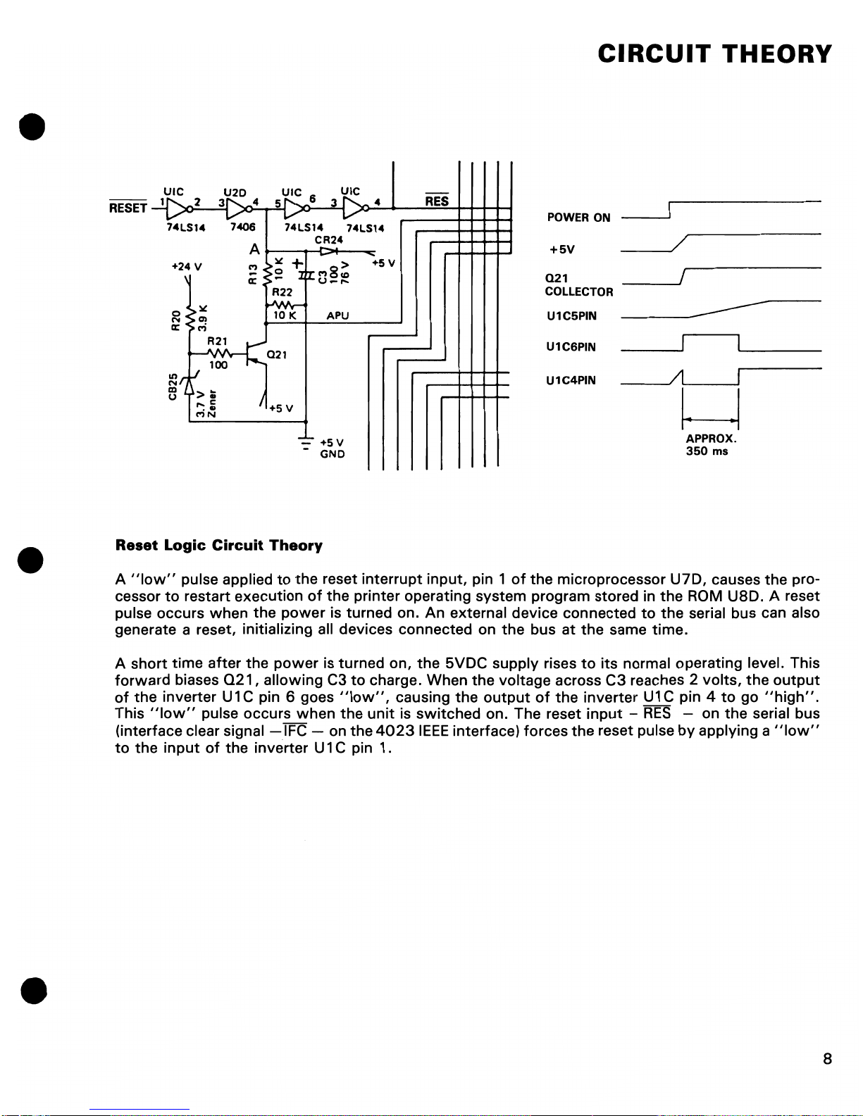
Reset
Logic
Circuit
Theory
POWER ON
+5V
021
COLLECTOR
U1C5PIN
U1C6PIN
U1C4PIN
--------
APPROX.
350
ms
A
"low"
pulse applied
to
the
reset
interrupt
input,
pin 1
of
the
microprocessor
U7D,
causes
the
pro-
cessor
to
restart
execution
of
the
printer
operating
system
program stored in
the
ROM USD. A reset
pulse
occurs
when
the
power
is
turned
on.
An
external device connected
to
the
serial bus can also
generate a reset, initializing all devices connected on
the
bus
at
the
same
time.
A
short
time
after
the
power
is
turned
on,
the
5VDC
supply
rises
to
its
normal operating level. This
forward
biases
Q21,
allowing
C3
to
charge.
When
the
voltage across
C3
reaches 2
volts,
the
output
of
the
inverter U1C pin 6 goes
"low",
causing
the
output
of
the
inverter
U1C
pin 4
to
go
"high".
This
"low"
pulse
occurs
when
the
unit
is
switched
on. The reset
input -RES
- on
the
serial bus
(interface clear signal
-IFC
- on
the
4023
IEEE
interface)
forces
the
reset pulse
by
applying a
"Iow"
to
the
input
of
the
inverter U 1 C pin 1.
S
1526
AND
4023
CIRCUIT
THEORY
V1
..
MHz
l..r----?":
- , .
R56
--0-1--
L _
___
'~:
"
R55
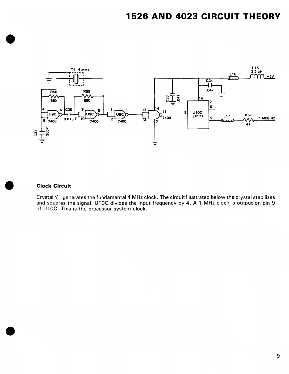
Clock Circuit
Crystal Y 1 generates
and squares
of
U 1
OC.
the
This is
signal. U 1
the
-~
7400
the
fundamental 4 MHz
OC
processor system clock.
7400
divides
the
input
11
D-
74
7
clock.
The
frequency by
"
.,
"I'"
o
C!
-
--......::..j
00
circuit
8 U10C
74177
illustrated
4.
A 1 MHz
C34
.04~
9
below
clock
117
the
R57
47
crystal stabilizes
is
output
1.15
2.2
"H
1 MEG
on pin 9
HZ
9
1526
+26V
AND
4023
CIRCUIT
THEORY
U5D
6532
6522
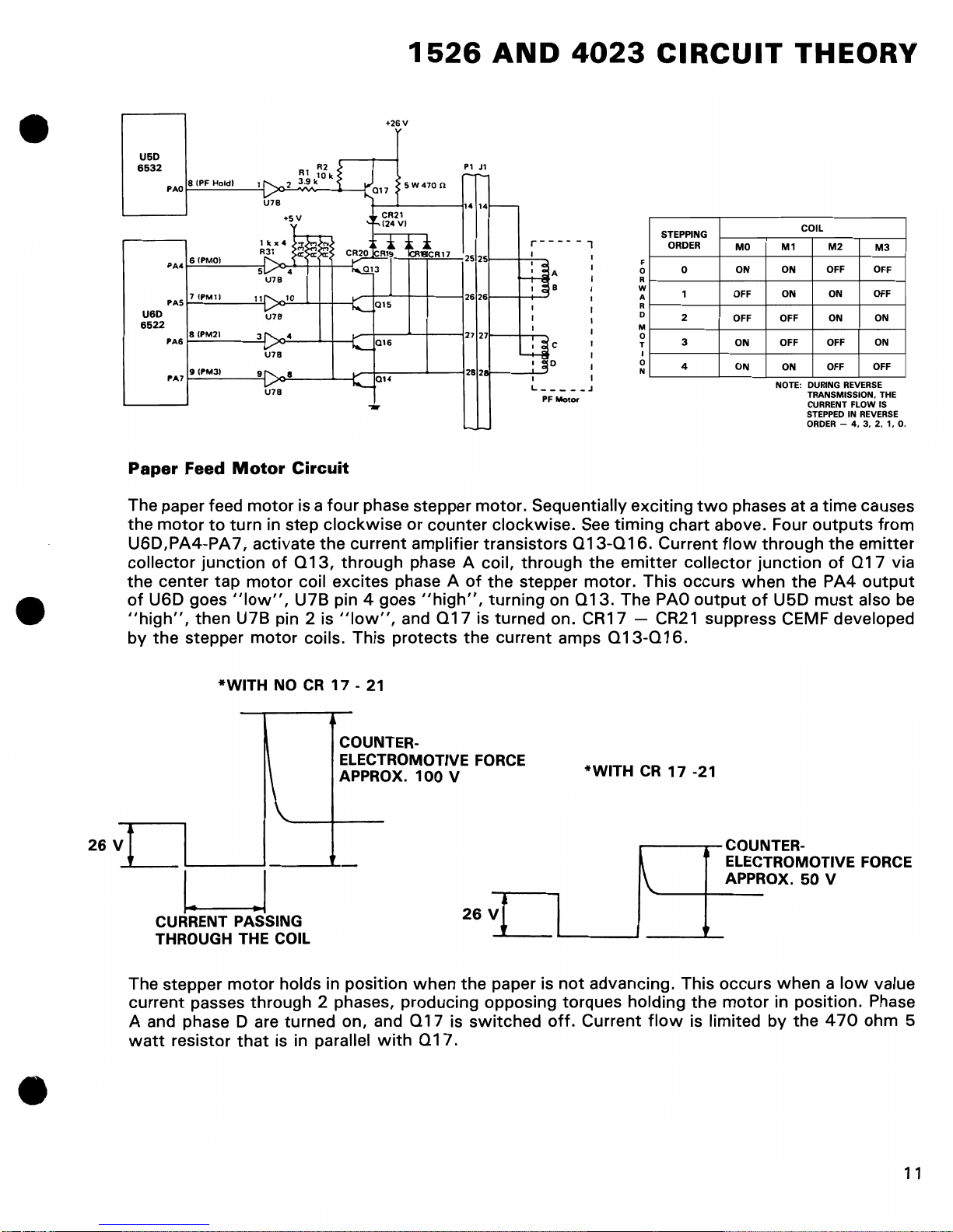
Paper
U6D
PAO
PA4
PAS
PA6
PA7
81PF
Holdl
61PMOI
7
(PM1)
81PM21
IllPM31
Feed
Motor
The paper feed
the
motor
to
turn
11
3
9
Circuit
motor
is a
four
phase stepper motor. Sequentially exciting
in step clockwise or counter clockwise. See timing chart above. Four
Pl
1.
2S
2626
27 27
282
2S
Jl
14
A
B
I
L
_____
PF
Motor
U6D,PA4-PA 7, activate the current amplifier transistors
collector
the
of
U6D goes
"high",
by
the stepper
junction
center tap
motor
"low",
then U7B pin 2 is
motor
of
013,
through phase A coil, through
coil excites phase A
U7B pin 4 goes
"low",
coils. This protects
"high",
and 0
of
the stepper motor. This occurs
turning on 0
17
is turned on. CR17 -
the
current amps
.J
013-016.
the
emitter
13.
The
013-016.
STEPPING
ORDER
F
0
R
W
A
R
0
M
0
T
I
0
N
Current
PAO
CR21
COIL
0
1
2
3
4
MO
M1
ON
ON
OFF
OFF
two
phases at a time causes
ON
OFF
ON
OFF
ON
ON
NOTE: DURING REVERSE
M2 M3
OFF
ON
ON
OFF
OFF
TRANSMISSION. THE
CURRENT FLOW IS
STEPPED
IN
ORDER -
4.
outputs
flow
collector
when
output
through
junction
of
U5D
the
the
of
PA4
must
017
suppress CEMF developed
OFF
OFF
ON
ON
OFF
REVERSE
3. 2. 1.
O.
from
emitter
via
output
also
be
*WITH
26
V
The stepper
current passes through
A and phase
watt
resistor
NO
CR
17 -21
COUNTERELECTROMOTIVE
APPROX.
motor
holds
in
position
2 phases, producing opposing torques holding
0 are turned on, and
that
is in parallel
with 0 17.
100
when
017
FORCE
V
*WITH
CR
17
-21
.---r-COUNTER-
__
--"~
L.
26
V=!~~~~""
the
paper is
is
switched
not
advancing. This occurs when a
off.
Current
flow
I ELECTROMOTIVE
_ _ APPROX.
the
motor
in position. Phase
is limited by the
50
V
low
470
FORCE
value
ohm 5
11
 Loading...